Technical Reference Manual - Bass United Fire and Security
138
QS4 Fire Alarm Control Panel Technical Reference Manual P/N 3100186 • Rev 2.0 • 12JUL01
Transcript of Technical Reference Manual - Bass United Fire and Security

QS4 Fire Alarm Control PanelTechnical Reference Manual
P/N 3100186 • Rev 2.0 • 12JUL01

Copyright © 2001. All rights reserved.
Compliance Statement The QS4, hereinafter referred to as the FACP or control panel, whenproperly installed, operates as a Local Protected Premises Fire AlarmSystem in accordance with the following standards:
• NFPA Standard 72, 1999 Edition
• Underwriters Laboratories Standard 864, 7th Edition
• Underwriters Laboratories of Canada Standard ULC S527
In addition, Auxiliary Fire Alarm System operation requires a ReversePolarity Module (RPM). Central Station Fire Alarm System operationrequires a Dialer card (DLD).
Installation in accordance with this manual, applicable codes, and theinstructions of the authority having jurisdiction is mandatory.
Limitation of Liability Edwards Systems Technology (EST) shall not under any circumstancesbe liable for any incidental or consequential damages arising from lossof property or other damages or losses owing to the failure of ESTproducts beyond the cost of repair or replacement of any defectiveproducts. EST reserves the right to make product improvements andchanges to product specifications at any time.
While every precaution was taken during the preparation of thisdocument to ensure its accuracy, EST assumes no responsibility forerrors or omissions.
Fire Alarm SystemLimitations
Automatic fire alarm systems can not guarantee against propertydamage, loss of property, or loss of life. An automatic fire alarm system'sability to provide early warning of a developing fire may be limited for avariety of reasons, but mainly due to improper installation ormaintenance.
The best way to minimize system failures is to perform regularlyscheduled preventive maintenance in accordance with national and localfire codes. All system components and wiring should be tested andmaintained by trained fire alarm system professionals.
FCC Compliance Statement This equipment can generate and radiate radio frequency energy. If thisequipment is not installed in accordance with this manual, it may causeinterference to radio communications. This equipment has been testedand found to comply within the limits for Class A computing devicespursuant to Subpart B of Part 15 of the FCC Rules. These rules aredesigned to provide reasonable protection against such interferencewhen this equipment is operated in a commercial environment.Operation of this equipment is likely to cause interference, in which casethe user at his own expense, will be required to take whatever measuresmay be required to correct the interference.

QS4 Technical Reference Manual i
Content
About this manual • iiiRelated documentation • ivDocument history • vi
Chapter 1 Product description • 1.1System overview • 1.2Component descriptions • 1.3Circuit descriptions • 1.5Controls and indicators • 1.9Controls and indicators behind the flip-down cover • 1.10Controls and indicators on the zone annunciator card • 1.11Interpretation of screen displays • 1.12
Chapter 2 Installation • 2.1Installation do's and don'ts • 2.2Installation checklist • 2.3Two ways to install the cabinet: Surface or semi-flush mount • 2.4How to assemble the panel • 2.6Wiring mains ac and earth ground • 2.7System jumper settings • 2.8System addressing • 2.10Terminal definitions • 2.14Connecting a PT–1S printer • 2.22Installing standby batteries • 2.23
Chapter 3 Operating instructions • 3.1Instructions for the Level 1 operator (public mode access) • 3.2Instructions for the Level 2 operator (emergency mode access) • 3.5Instructions for the Level 3 operator (maintenance mode access) • 3.7Instructions for the Level 4 operator (service mode access) • 3.10QuickReference list • 3.11
Chapter 4 Programming instructions • 4.1Overview • 4.2QuickStart setup instructions • 4.4Customizing the system configuration • 4.13Setting up an Output Group • 4.21Setting up a Zone • 4.26
Chapter 5 Standard applications • 5.1Notification appliance circuits • 5.2Initiating device circuits • 5.5Coded alarm signaling • 5.8Remote station protective signaling system • 5.10Auxiliary protective signaling • 5.12
Chapter 6 Maintenance instructions • 6.1Pseudo point definitions • 6.2Maintenance tasks • 6.6

Content
ii QS4 Technical Reference Manual
Appendix A System calculations • A.1Notification appliance circuit maximum wire length calculation • A.2Signature loop maximum wire length calculations • A.3Battery calculation worksheet • A.8
Appendix B Barcode library • B.1
Appendix C SIGA-REL programming • C.1Application block diagram • C.2Programming instructions • C.3

Content
QS4 Technical Reference Manual iii
About this manual
Organization This manual provides information on how to properly install, wire, andmaintain the FACP and related components, and is organized asfollows:
Chapter 1 provides a detailed description of the fire alarm control paneland its operation.
Chapter 2 provides instructions for installing the fire alarm controlpanel.
Chapter 3 provides instructions for operating the control panel.
Chapter 4 provides instructions for programming the fire alarm systemfrom the front panel.
Chapter 5 provides simplified wiring schematics for standardapplications.
Chapter 6 provides instructions for maintaining the system.
Appendix A provides worksheets for calculating maximum wire lengthsfor notification and Signature circuits, and for sizing standby batteries.
Appendix B provides a set of bar codes that you can use to enter textfor location messages.
Appendix C provides information on how to program the SIGA–RELusing the QS–CU (QuickStart Configuration Utility).
Safety information Important safety admonishments are used throughout this manual towarn of possible hazards to persons or equipment.
WARNING: Warnings are used to indicate the presence of a hazardwhich will or may cause personal injury or death, or loss of service ifsafety instructions are not followed or if the hazard is not avoided.
Caution: Cautions are used to indicate the presence of a hazard whichwill or may cause damage to the equipment if safety instructions are notfollowed or if the hazard is not avoided.

Content
iv QS4 Technical Reference Manual
Related documentation
National Fire Protection Association1 Batterymarch ParkP.O. Box 9101Quincy, MA 02269-9101
NFPA 70 National Electric Code
NFPA 72 National Fire Alarm Code
NFPA 11 Low-Expansion Foam Systems
NFPA 11A Medium- and High-Expansion Foam Systems
NFPA 12 Carbon Dioxide Extinguishing Systems
NFPA 13 Sprinkler Systems
NFPA 15 Water Spray Fixed Systems for Fire Protection
NFPA 16 Deluge Foam-Water Sprinkler and Foam-Water SpraySystems
NFPA 17Dry Chemical Extinguishing Systems
Underwriters Laboratories, Inc.333 Pfingsten RoadNorthbrook, IL 60062-2096
UL 38 Manually Actuated Signaling Boxes
UL 217 Smoke Detectors, Single & Multiple Station
UL 228 Door Closers/Holders for Fire Protective SignalingSystems
UL 268 Smoke Detectors for Fire Protective Signaling Systems
UL 268A Smoke Detectors for Duct Applications
UL 346 Waterflow Indicators for Fire Protective SignalingSystems
UL 464 Audible Signaling Appliances
UL 521 Heat Detectors for Fire Protective Signaling Systems
UL 864 Standard for Control Units for Fire Protective SignalingSystems
UL 1481 Power Supplies for Fire Protective Signaling Systems
UL 1638 Visual Signaling Appliances
UL 1971 Visual Signaling Appliances
Underwriters Laboratories ofCanada7 Crouse RoadScarborough, ONCanada M1R 3A9
Canadian Electrical Code Part 1
ULC S527 Standard for Control Units for Fire Alarm Systems
ULC S524 Standard for the Installation of Fire Alarm Systems
ULC S536 Standard for the Inspection and Testing of FireAlarm Systems
ULC S537 Standard for the Verification of Fire Alarm Systems
ULC ORD–C693–1994 Central Station Fire Protective SignalingSystem and Services

Content
QS4 Technical Reference Manual v
Edwards Systems Technology6411 Parkland DriveSarasota, FL 34243
2–CTM City Tie Module Installation Sheet (P/N 270496)
CDR–3 Bell Coder Installation Sheet (P/N 3100023)
DLD Dual Inline Dialer Installation Sheet (P/N 3100187)
PS6 Power Supply Card Installation Sheet (P/N 3100201)
QSA–1(X), QSA–2(X) Remote Annunciator Cabinet InstallationSheet (P/N 3100295)
QS–CPU(X) CPU/Display Unit Installation Sheet (P/N 3100276)
SL30, SL30–1 LED/Switch Card Installation Sheet (P/N3100193)
SLIC Signature Intelligent Controller Card Installation Sheet(P/N 3100192)
RS485 (NT–A) Card and QS–232 UART Module InstallationSheet (P/N 3100191)
ZA8–2 Class A Zone Card Installation Sheet (P/N 3100189)
ZB16–4 Class B Zone Card Installation Sheet (P/N 3100188)
ZR8 Relay Card Installation Sheet (P/N 3100190)
SIGA–APS Auxiliary Power Supply Installation Sheet (P/N387342)
Signature Series Intelligent Smoke and Heat DetectorsApplications Bulletin (P/N 270145)
Signature Series Component Installation Manual (P/N 270497)
EST Strobe Applications Guide (P/N 85000-0049)
QuickStart Online Help Utility (P/N 7350047)
QuickStart ULI and ULC Compatibility Lists (P/N 3100335)
Network Hardware Technical Reference (P/N 250100)

Content
vi QS4 Technical Reference Manual
Document history
Date Revision Description of changes
24JUN01 1.0 Original release.
12JUL01 2.0 Corrections and additions on pp 2.12, 2.24, 3.9, 4.4, 4.8, 4.10, 4.19,A.3.

QS4 Technical Reference Manual 1.1
Chapter 1 Product description
SummaryThis chapter provides a detailed description of the fire alarm controlpanel and its operation.
ContentSystem overview • 1.2Component descriptions • 1.3Circuit descriptions • 1.5Controls and indicators • 1.9Controls and indicators behind the flip-down cover • 1.10Controls and indicators on the zone annunciator card • 1.11Interpretation of screen displays • 1.12

Product description
1.2 QS4 Technical Reference Manual
System overviewSystem hardware capabilitiesHardware capabilities vary depending on cabinetsize and option card configuration, but generally:
• Up to four Class A or Class B Signaturesignaling line circuits that support up to 250single-address Signature devices each
• Up to 40 Class A or 48 Class B initiating devicecircuits (IDC). Combination systems can notexceed 40 IDC circuits total
• Up to 16 Class A or 20 Class B notificationappliance
• Up to two 30-zone displays
• Up to 96 dry-contact relay
• 4.5 amps of 24 Vdc power for externalnotification appliances
• Battery charger capable of charging batteriesrated up to 40 Ah. Maximum battery size forULC applications is 30 Ah
• Up to eight, fully-supervised, mirrored orcustomized remote annunciators
Minimum system requirementsA Local Protected Premises Fire Alarm Systemrequires only the FACP (CPU, PS6, andenclosure) with at least one SLIC, ZB16–4, orZA8–2 card programmed with at least one audibleoutput circuit and one alarm input circuit.
In addition to the hardware requirements of aLocal system:
• Add a 2–CTM City Tie Module for an AuxiliaryFire Alarm System
• Add a DLD Dual Line Dialer Card or RPMReverse Polarity Module for a RemoteSupervising Station Fire Alarm System
• Add a DLD Dual Line Dialer Card or RPMReverse Polarity Module for a Central StationFire Alarm System
• Add a SIGA–REL for Releasing Device Service
Normal operating mode descriptionThe panel operates in normal mode in theabsence of any alarm, supervisory, trouble, and
monitor events. In normal mode, the control panelmonitors the system for any events.
Off-normal operating mode descriptionThe panel operates in off-normal mode any timethere is an event introduced into the system.When this happens, the CPU:
• Changes the contact positions on theappropriate common relays
• Activates all common alarm outputs (alarmevents only)
• Turns on the panel buzzer
• Executes the appropriate programmed outputresponse for the input that signaled the event
• Sends a record of the event to the appropriatedisplay queue and out the serial port
If there is no operator in attendance, the paneldisplays the content of the highest priority displayqueue containing a record.
If there is an operator in attendance, the paneldisplays the content of the current display queueregardless of any new events introduced into thesystem.
Failsafe operating mode descriptionThe panel operates in failsafe mode when theCPU loses the ability to communicate with the PS6and JP1 on the PS6 is in the ON position. Whenthis happens, the power supply:
• Closes the common trouble relay contacts
• Instructs the dialer to send the default troublemessage
• Monitors the system for any alarm events
If an alarm event occurs, the power supply:
• Changes the contact positions on the commonalarm relay
• Turns on all conventional common alarmoutputs. Signature common alarm outputs arenot affected.
• Instructs the dialer to send the default alarmmessage

Product description
QS4 Technical Reference Manual 1.3
Component descriptions
1 2 3 6A 5 6B 7 84
9
10
J5
13
JP1
J2
J7
J8
JP1 CONFIGURATIONPIN 1 & 2 = MODEM PWR
PIN 2 & 3 = RTS
J6
14 13 111215
1. Cabinet enclosure: Houses the panelelectronics and standby batteries.
2. SL30–1 LED/Switch Card: Provides thirtycircuits for point or zone annunciation. Eachcircuit has two LEDs for annunciating alarm,supervisory, and trouble signals, and a buttonnumbered from 31 to 60.
3. SL30 LED/Switch Card: Same as SL30–1except the buttons are numbered 1–30.
4. CPU/Display: Provides operator access tosystem messages, status information, andprogramming menus, and executes systemresponses based on the panel programming.
5. PS6 Power Supply Card: Provides primary dcpower to the panel electronics and externalcircuits. The PS6 also provides common alarm,supervisory and trouble relays for remote stationsupervision.

Product description
1.4 QS4 Technical Reference Manual
6. RS485 (NT–A) Class A Card: The NT–Acomprises the RS485 card and QS–232 UARTmodule. Together these provide an additionalRS–232 channel to allow Class A communicationbetween the control panel and other remoteannunciator panels. Control panels requireinstallation of both cards while remoteannunciator panels only require installation of aQS–232 card and only then if you want toconnect a printer or service computer.
7. ZA8–2 Class A Conventional Zone Card:Provides six dedicated Class A initiating devicecircuits (IDCs) for connecting two-wire smokedetectors and dry-contact initiating devices. TheZA8–2 also provides two circuits that you canconfigure as IDCs or as 24 Vdc notificationappliance circuits (NACs).
8. ZB16–4 Class B Conventional Zone Card:Provides twelve dedicated Class B initiatingdevice circuits (IDCs) for connecting two-wiresmoke detectors and dry-contact initiatingdevices. The ZB16–4 also provides four circuitsthat you can configure as IDCs or as Class B 24Vdc notification appliance circuits (NACs).
9. QS–Cable12 Expansion Cable: Extends theCPU data and power bus to circuit cards installedon the lower DIN rail in the 12-option cabinet.
10. ZR8 Relay Card: Provides eight dry-contactrelays. You can configure each relay fornormally-open or normally-closed operation.
11. DLD Dual Line Dialer Card: Provides twotelephone line connections for sending systemmessages to a compatible Digital AlarmCommunicator Receiver.
12. SLIC Signature Loop Intelligent ControllerCard: Provides one Class A or Class B signalingline circuit (loop) for connecting Signature seriesdetectors and modules. The SLIC also providestwo Class A or Class B notification appliancecircuits (NACs) for connecting polarized 24 Vdcnotification appliances (horns, strobes).
13. Standby batteries: Provides dc power to thepanel electronics in the absence of ac power.
14. Transformer: Changes the mains ac supplyvoltage for the power supply card.
15. AC wiring block and fuse holder: Providesconnections for mains ac (primary power) and 5Afuse.

Product description
QS4 Technical Reference Manual 1.5
Circuit descriptions
PS6 Power Supply Card1. Relay 1 (Common Alarm)
Style: Form CContact rating: 1 A @ 20.4 – 26.4 Vdc (0.6 PF)Wire size: 18 to 12 AWG (0.75 to 2.5 mm²)Nonsupervised and power-limited only whenconnected to a power-limited source
2. Relay 2 (Common Supervisory)Style: Normally-openContact rating: 1 A @ 20.4 – 26.4 Vdc (0.6 PF)Wire size: 18 to 12 AWG (0.75 to 2.5 mm²)Nonsupervised and power-limited only whenconnected to a power-limited source
3. Relay 3 (Common Trouble)Style: Normally-open, held closedContact rating: 1 A @ 20.4 – 26.4 Vdc (0.6 PF)Wire size: 18 to 12 AWG (0.75 to 2.5 mm²)Nonsupervised and power-limited only whenconnected to a power-limited source
4. Relay 4 (Programmable)Style: Normally-openContact rating: 1 A @ 20.4 – 26.4 Vdc (0.6 PF)Wire size: 18 to 12 AWG (0.75 to 2.5 mm²)Nonsupervised and power-limited only whenconnected to a power-limited source
5. Smoke/Accessory PowerOutput: Continuous or interruptible via jumperselectionVoltage: 24 Vdc, regulatedCurrent: 250 mAWire size: 18 to 12 AWG (0.75 to 2.5 mm²)Supervised and power-limited
71
2 6
9 8
53 4
6. RS485Wire size: 18 to 12 AWG (0.75 to 2.5 mm²)Wire type: Twisted pair, six twists per footminimumCircuit capacitance: 0.4 µFCircuit resistance: 100 ΩSupervised and power-limited
8. AUX Power #1, #2, and #3Voltage: 17.5 – 26.4 Vdc FWR (full waverectified)Current: 1.5 A eachWire size: 18 to 12 AWG (0.75 to 2.5 mm²)Power-limited and supervised for short circuitconditions only
7. RS232Wire size: 18 to 12 AWG (0.75 to 2.5 mm²)Nonsupervised and power-limitedWire length: 20 ft maximimum
9. Battery CircuitCharge current: 2 ACharge capacity: 40 Ah (UL), 30 Ah (ULC)Supervised and nonpower-limited

Product description
1.6 QS4 Technical Reference Manual
SLIC Signature Loop Intelligent Controller Card circuits
1. NAC #1Configuration: Class B or Class AOutput voltage: 24 Vdc, nominalOutput current: 2.0 A @ 24 VdcWire size: 18 to 12 AWG (0.75 to 2.5 mm2)End of line resistor: 10 kΩ, 1/2WSupervised and power-limited
2. NAC #2Configuration: Class B or Class AOutput voltage: 24 Vdc, nominalOutput current: 1.0 A @ 24 VdcWire size: 18 to 12 AWG (0.75 to 2.5 mm2)End of line resistor: 10 kΩ, 1/2WSupervised and power-limited
3. Signature LoopConfiguration: Class B (Style 4) or Class A (Style 6)Capacity: 125 Signature detectors, 125 Signature single-addressmodulesWire size: 18 to 12 AWG (0.75 to 2.5 mm2)Circuit resistance: 65 ΩCircuit capacitance: 0.3 µFSupervised and power-limited
4. NAC Riser In/OutVoltage: 24 Vdc, nominalWire size: 18 to 12 AWG (0.75 to 2.5 mm2)
1 2
4 3
ZR8 Relay Card circuits
1. Dry-contact relays R1 – R4Outputs: Normally-open or normally-closed contacts via jumperselectionContact rating: 24 Vdc @ 1.0 AWire size: 18 to 12 AWG (0.75 to 2.5 mm2)Nonsupervised, and power-limited only when connected to apower-limited source
2. Dry-contact relays R5 – R8Outputs: Normally-open or normally-closed contacts via jumperselectionContact rating: 24 Vdc @ 1.0 AWire size: 18 to 12 AWG (0.75 to 2.5 mm2)Nonsupervised, and power-limited only when connected to apower-limited source
1
2

Product description
QS4 Technical Reference Manual 1.7
ZB16–4 Class B Conventional Zone Card circuits
1. IDC Circuits Z1 – Z12Wiring configuration: Class BDetector voltage: 20.33 – 24.76 Vdc, max ripple 2000 mVShort circuit current: 75.9 mA, max.Resistance: 50 Ω, max.Capacitance: 100 µF, maxWire size: 18 to 12 AWG (0.75 to 2.5 mm2)End of line resistor: 4.7 kΩ, 1/2WSupervised and power-limited
2. NAC Circuits Z13 – Z16Wiring configuration: Class BOutput voltage: 24 Vdc, nominalOutput current: 2.0 A @ 24 VdcWire size: 18 to 12 AWG (0.75 to 2.5 mm2)End of line resistor: 10 kΩ, 1/2WSupervised and power-limitedIDC specifications apply when programmed as IDC circuit
3. R1Voltage: 24 Vdc, nominalWire size: 18 to 12 AWG (0.75 to 2.5 mm2)
4. R2Voltage: 24 Vdc, nominalWire size: 18 to 12 AWG (0.75 to 2.5 mm2)
13
4
2
1
ZA8–2 Class A Conventional Zone Card circuits
1. IDC Circuits Zone 1 – Zone 3, Zone 5 – Zone 7Wiring configuration: Class ADetector voltage: 19.90 – 22.46 Vdc, max ripple 2000 mVShort circuit current: 75.9 mA, max.Resistance: 50 Ω, max.Capacitance: 100 µF, maxWire size: 18 to 12 AWG (0.75 to 2.5 mm2)End of line resistor: 4.7 kΩ, 1/2WSupervised and power-limited
2. NAC Circuits Zone 4, Zone 8Wiring configuration: Class AOutput voltage: 24 Vdc, nominalOutput current: 2.0 A, 24 VdcWire size: 18 to 12 AWG (0.75 to 2.5 mm2)End of line resistor: 10 kΩ, 1/2WSupervised and power-limitedIDC specifications apply when programmed as IDC circuit
3. NAC PWR IN (Zone 4)Voltage: 24 Vdc, nominalWire size: 18 to 12 AWG (0.75 to 2.5 mm2)
4. NAC PWR IN (Zone 8)Voltage: 24 Vdc, nominalWire size: 18 to 12 AWG (0.75 to 2.5 mm2)
1
23
1 42
Product description
1.8 QS4 Technical Reference Manual
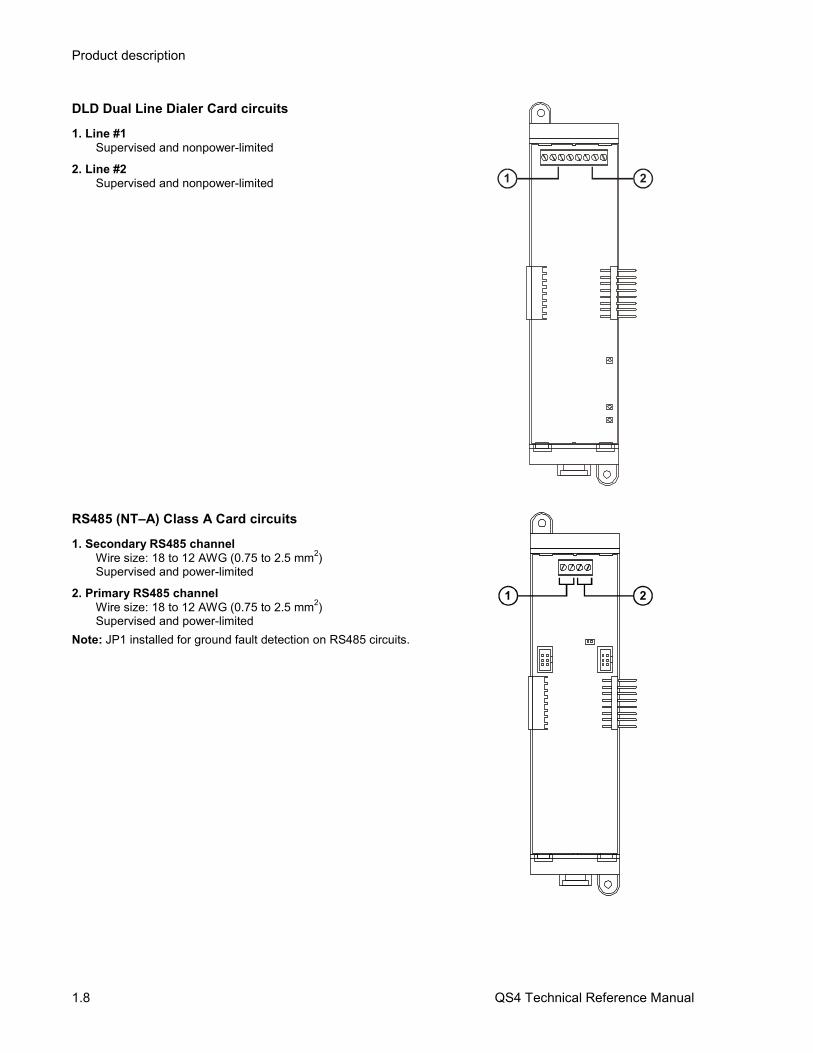
DLD Dual Line Dialer Card circuits
1. Line #1Supervised and nonpower-limited
2. Line #2Supervised and nonpower-limited 1 2
RS485 (NT–A) Class A Card circuits
1. Secondary RS485 channelWire size: 18 to 12 AWG (0.75 to 2.5 mm2)Supervised and power-limited
2. Primary RS485 channelWire size: 18 to 12 AWG (0.75 to 2.5 mm2)Supervised and power-limited
Note: JP1 installed for ground fault detection on RS485 circuits.
1 2

Product description
QS4 Technical Reference Manual 1.9
Controls and indicators
1 2 3 4
1
6 7 8 9 0
2
3
5
4
5
6
7
8
9
10
11
12
13
14
15
16
17
18
19
20
21
22
23
24
25
26
27
28
29
30
12
2 3 4 5 61 7 8 9
1
2
3
4
5
6
7
8
9
10
11
12
13
14
15
16
17
18
19
20
21
22
23
24
25
26
27
28
29
30
11 10
1. Text display and controls: Displays systemmessages, status information, programmingmenus.
Moves the cursor up one line at a time orto the previous record in the displayqueue
Moves the cursor down one line at a timeor to the next record in the display queue
Moves the cursor right one character at atime or to the next display queue
Moves the cursor left one character at atime or to the previous display queue
Enters operator input and selects menuitems
2. Alarm LED: Indicates the panel posted analarm event record into the corresponding displayqueue.
3. Supervisory LED: Indicates the panel posteda supervisory event record into the correspondingdisplay queue.
4. Disable/Test LED: Indicates part of thesystem is disabled or is currently under test.Disabled components also signal a systemtrouble.
5. Monitor LED: Indicates the panel posted amonitor event record into the correspondingdisplay queue.
6. Trouble LED: Indicates the panel posted atrouble event record into the correspondingdisplay queue.
7. Ground Fault LED: Indicates a ground fault inthe system wiring. Ground faults also signal asystem trouble.
8. CPU Fail LED: Indicates an unexpectedreboot or failure with the microprocessor. CPUfailures also signal a system trouble.
9. Power LED: Indicates the panel has ac power.
10. Panel Silence/Acknowledge button/LED:Turns off the panel buzzer and acknowledges allevents. The Panel Silenced LED indicates that alloff normal events have been acknowledged andthe internal buzzer is off.
11. Status button: Displays the Status menufrom which you can identify active or disabledpoints in the system.
12. Help button: Provides additional informationfor the event record selected on the display.

Product description
1.10 QS4 Technical Reference Manual
Controls and indicators behind the flip-down cover
1 2 3 4
1
6 7 8 9 0
2
3
5
4
5
6
7
8
9
10
11
12
13
14
15
16
17
18
19
20
21
22
23
24
25
26
27
28
29
30
1
2
3
4
5
6
7
8
9
10
11
12
13
14
15
16
17
18
19
20
21
22
23
24
25
26
27
28
29
30
3
6
9
5
8
4
7
2 1
1. Enable Controls key switch: Gives priorityaccess to control functions reserved for operatorswith Level 2 access.
2. Barcode scanner jack: Input point for optionalbarcode scanner.
3. Numeric keypad: Numbered buttons forentering data and selecting menu options.
4. Reset button: Restores devices or zones inalarm or trouble to their standby condition. TheLED indicates when the panel is resetting.
5. Alarm Silence button: Turns activenotification appliances off according to the panelprogramming. Pressing Alarm Silence a secondtime turns them back on. The LED indicateswhen the panel is in alarm and operating withnotification appliances turned off.
6. Drill button: Turns notification appliances onaccording to the panel programming but does notplace the panel in alarm. The LED indicateswhen the panel is in Drill mode.
7. Menu button: Displays the operator menus.
8. Delete button: Returns to the previous menuor back spaces the cursor.
9. Enter button: Press the Enter button to acceptinformation from the operator or continue to thenext item.

Product description
QS4 Technical Reference Manual 1.11
Controls and indicators on the zone annunciator card
1
2
3
4
5
6
7
8
9
10
11
12
13
14
15
16
17
18
19
20
21
22
23
24
25
26
27
28
29
30
21 3
1. Zone display button: Displays an eventrecord for each device in the corresponding zonethat signaled an alarm.
2. Zone active LED: Indicates a device in thecorresponding zone signaled an alarm condition.
3. Zone trouble LED: Indicates a device orwiring fault in the corresponding Zone.
Note: ULC requires that every fire panel have thecapability to visually display system status bymeans of specific indicators for each zone. Allstatus changes must clearly indicate that theinformation is an Alarm (ALM), Supervisory(SUP), Trouble (TBL), or Monitor (MON).

Product description
1.12 QS4 Technical Reference Manual
Interpretation of screen displays
HH:MM:SS MM/DD
System Normal
Project Name
Alarm History:nnnn
This is what the panel display looks like when there are no eventrecords posted in a display queue.
HH:MM:SS is the current time in hours, minutes, and seconds
MM/DD is the current month and date
nnnn is the number times the panel went into alarm since beingplaced into service
HH:MM:SSAxxx Dxxx
nnn event nameCustom message 1Custom message 2
nnn event nameCustom message 1Custom message 2
ALM SUP TRBL MONaaa sss ttt mmm
This is what the panel display looks like when there are eventrecords posted in a display queue.
HH:MM:SS is the current time in hours, minutes, and seconds
Axxx is the current number of active points
Dxxx is the current number of disabled points
These items comprise the event record:
nnn is the posting sequence number (001 = first, 002 = second, andso on)
event name is the event produced when the device changed states.Refer to Table 1-1.
P:pp C:cc D:ddd is the address of the device that signaled theevent (P = panel number, C = card number, D = device number)
The event record may also include a custom message that typicallyindicates the location of the device, depending on the panelprogramming.
These items indicate the content of the display queues:
aaa is the number of alarm event records (highest priority)
sss is the number of supervisory event records
ttt is the number of trouble event records
mmm is the number of monitor event records (lowest priority)

Product description
QS4 Technical Reference Manual 1.13
Table 1-1: Event descriptions
Event name Event type Description
ALARM ACTIVE Alarm Smoke detector active
ALARM VERIFY Monitor Alarm active. Performing auto reset.
AND GROUP Alarm And group active
BAD PRSONATY Trouble SIGA personality mismatch
BAD TYPE Trouble SIGA type mismatch
COMM FAULT Trouble Communication failure
DEV COMPATIB Trouble SIGA compatibility fault
DIRTY HEAD Trouble Dirty smoke detector. No compensation remaining
DISAB SOUND Trouble Sounder is disabled (EN–54 only)
DISABLED Trouble Device is disabled
GROUND FAULT Trouble Ground fault
HEAT ALARM Alarm Heat detector active
INTERNAL TBL Trouble Internal system trouble
LCL MONITOR Monitor Common monitor
LCL TROUBLE Trouble Generic trouble.
MAINT ALERT Monitor Dirty smoke detector. Some compensation remaining
MATRIX GROUP Alarm Matrix group active
MONITOR Monitor Active non-latching input circuit.
OBJECT RUN Monitor Service group is enabled and governing all defined objects
PREALARM Monitor Possible fire condition exists.
PULL STATION Alarm Manual fire alarm box active
SERVICE GROUP Trouble Service group active
SUPERVISORY Supervisory A device used to monitor a component of the fire suppression system is active
SWITCH Monitor Operator presses switch on LED/Switch card
TAMPER Supervisory Sprinkler tamper active
TEST Trouble A member of a Service group under test is activated
TIME CONTROL Monitor Time control active
TROUBLE Trouble Common trouble
TROUBLE OPEN Trouble Open detected on a supervised output device's field wiring
TROUBLE SHORT Trouble Short detected on a supervised output device's field wiring
UNEXPECT DEV Trouble Signature device not defined in database
WATERFLOW Alarm Water flowing through the sprinkler system
ZONE ALARM Alarm Alarm zone active
ZONE MONITOR Monitor Monitor zone active
ZONE SUPER Supervisory Supervisory zone active

Product description
1.14 QS4 Technical Reference Manual

QS4 Technical Reference Manual 2.1
Chapter 2 Installation
SummaryThis chapter provides instructions for installing the fire alarm controlpanel.
ContentInstallation do's and don'ts • 2.2Installation checklist • 2.3Two ways to install the cabinet: Surface or semi-flush mount • 2.4How to assemble the panel • 2.6Wiring mains ac and earth ground • 2.7System jumper settings • 2.8System addressing • 2.10Terminal definitions • 2.14Connecting a PT–1S printer • 2.22Installing standby batteries • 2.23Connecting a service computer • 2.24

Installation
2.2 QS4 Technical Reference Manual
Installation do's and don'tsWhen installing cabinets... DO use fasteners that can support the full weight of the
cabinet and standby batteries. Tighten firmly to avoidvibrations.
DO NOT drill inside the cabinet with circuit cards installed.Remove all metal filings before installing the circuit cards.
DO NOT recess the cabinet into the wall deeper than 2–11/16inches (68.2 mm) from the finished wall surface to allow roomfor the trim kit.
When installing circuit boards... DO ground yourself with an approved static-protective wriststrap when handling circuit boards.
DO keep circuit boards in their protective antistatic packaging.Remove only for inspection or installation.
DO NOT touch component leads and connector pins whenhandling circuit boards.
DO disconnect ac power and batteries before installing orremoving circuit boards. Installing or removing circuit boardswhile the control panel is energized may damage theequipment.
When installing circuit wiring... DO use appropriately sized wire for the application.Incorrectly-sized wires degrade circuit performance.
DO make sure there are no wire-to-ground shorts or wire-to-wire shorts before connecting field wires to the panel.
DO NOT over tighten screw terminals. Over tightening maystrip screw terminal threads and cause loose connections.
When installing Signature loops... DO NOT install more than fifteen SIGA–UMs or MABsconfigured for two-wire smoke detectors on a loop.
DO NOT install more than seven SIGA–UMs or MABsconfigured for two-wire smoke detectors on loops with isolatordevices.
DO NOT install more than ten SIGA–RELs on a loop. Youmust use the QuickStart configuration utility to program aSIGA–REL. Refer to the technical manual supplied with theSIGA–REL and appendix C of this manual for programminginformation.
When installing standby batteries... DO NOT install standby batteries until after you completelyinstall and test the system.

Installation
QS4 Technical Reference Manual 2.3
Installation checklist
Prepare the site Make sure the installation location is free from constructiondust and debris, and immune to extreme temperature rangesand humidity.
Allow enough floor and wall space so the panel can beinstalled and serviced without obstructions.
Pull and tag all field wiring. See Appendix A for wire lengthcalculations.
Unpack the equipment Open the shipping container and carefully unpack theequipment. Check for any visible signs of damage. If there isany damage, return the equipment to the place of purchase.
Keep the container and packing material until after completelyinstalling and testing the equipment. Use the shippingcontainer to return the equipment to the manufacturer.
Verify the shipping container contains the correct parts. If anyparts are missing or damaged, return the equipment to themanufacturer.
Install the cabinet See Figure 2-1 for cabinet dimensions.
Assemble the panel Wire mains ac and earth ground Bring the primary power conductors into the left side
(nonpower-limited area) of the cabinet and wire to the acterminal block.
WARNING: Make sure that the circuit breaker providing acpower is switched off before connecting wires to the terminalblock.
Connect the field wiring Bring the field wiring into the power-limited area of the cabinet.Verify there are no open or shorts then connect the wires totheir respective terminals.
Use the AutoLearn andAutoLoop utilities to configurethe system
Refer to chapter 4.
Customize the systemconfiguration
Refer to chapter 4.
Install the standby batteries Do not connect standby batteries to the panel until aftercompletely testing the panel.

Installation
2.4 QS4 Technical Reference Manual
Two ways to install the cabinet: Surface or semi-flush mount
Surface mount instructions
1. Position the cabinet on thefinished wall surface.
2. Fasten the cabinet to thewall surface whereindicated. Tighten firmly.
4-7/8 in(123.8 mm)
Semi-flush mountinstructions
1. Frame the interior wall asrequired to support the fullweight of the cabinet andstandby batteries.
2. Fasten the cabinet to theframing studs whereindicated. Tighten firmly.
2-11/16 in(68.2 mm)
2-3/16 in(55.6 mm)

Installation
QS4 Technical Reference Manual 2.5
D1
D2
D3 D4
D5
DimensionsD1 D2 D3 D4 D5
5-optioncabinet
18 in(45.72 cm)
18-5/8 in(47.31 cm)
4-7/8 in(12.38 cm)
16-5/8 in(42.23 cm)
13 in(33.00 cm)
12-optioncabinet
30 in(76.2 cm)
18-5/8 in(47.31 cm)
4-7/8 in(12.38 cm)
16-5/8 in(42.23 cm)
25 in(63.50 cm)
Note: Add 1-1/2 in (3.81 cm) to D1 and D2 dimensions for trim kit.
Figure 2-1: Dimensions for 5-option and 12-option cabinets (arrows show mounting hole locations)

Installation
2.6 QS4 Technical Reference Manual
How to assemble the panel
Circuit card instructions
1. Lock the PS6 onto the DIN rail and configurejumpers.
2. Attach the ground wire to the cabinet. Tightenthe lock nut firmly to ensure a goodmechanical and electrical connection.
3. Plug the transformer into the PS6.
4. Install remaining option cards according totheir respective installation sheets.
Use a QS–Cable12 to connect option cards onthe top and bottom DIN rails in a 12-optioncabinet.
Door mounting instructions
1. Bolt the door to the cabinet back box.
2. Attach one end of the ground strap to the doorand the other to the back box.
3. Screw the CPU/Display unit to the cabinetdoor.
4. Plug one end of the ribbon cable into theCPU/Display and the other end into the PS6.
5. Screw the key switch ground wire and theCPU cover to the cabinet door.
*Actual cabinet door not shown

Installation
QS4 Technical Reference Manual 2.7
Wiring mains ac and earth ground
N(L2)
G(E)
H(L1)
CAUTION: The middle connection on the acterminal block makes a mechanical connectionto chassis (earth) ground. Do not allow the achot and neutral conductors to make contact withthe middle connector on the ac terminal block.
Wiring instructions
1. Bring the mains ac conductors into thecabinet through the 3/4–1/2 inch combinationknock-outs on the left side or upper leftcorner of the cabinet.
2. Wire the hot (H, L1), neutral (N, L2), andground (G, E) conductors to the ac terminalblock as shown.
3. Insert tabbed end of terminal block cover(deadfront) into the slot provided on the sideof the cabinet.
Notes
Keep power-limited wires in the shaded areaand nonpower-limited wires in the nonshadedarea.
Maintain a 1/4-inch separation between themains ac and battery wires (power-limited) andand all other nonpower-limited wiring at alltimes.

Installation
2.8 QS4 Technical Reference Manual
System jumper settings
PS6 Power Supply Card jumpersJP2 configures the Smoke/Accessory poweroutput for constant or resettable 24 Vdc.
• Set JP2 to ACC PWR to provide constant24 Vdc for external equipment.
• Set JP2 to SMK PWR to provide resettable24 Vdc for four-wire smoke detectors
JP1 configures the panel for failsafe operation.Failsafe allows the system to generate outputresponses even when the CPU losescommunication with the power supply card.
• Set JP1 to ON to turn failsafe mode on
• Set JP1 to OFF to turn failsafe mode off
JP2ACC PWR
SMK PWR
JP1
ON OFF
SLIC Signature Loop Intelligent ControllerCard jumpersJP1 and JP2 selects the signal that the SLICuses for the notification appliances connected toNAC1.
Note: NAC 2 always uses the external signalconnected to TB2–3 and TB2–4.
• Set JP1 and JP2 to INT to use the 24 Vdcthat comes from the PS6 over the busconnection.
• Set JP1 and JP2 to EXT to use the 24 Vdcthat comes from an external sourceconnected to TB2–3 and TB2–4.
CAUTION: Do not set JP1 and JP2 to EXT ifstrobes are connected to NAC 1 and a codedsignal is connected to TB2–3 and TB2–4.
JP1 JP2
INT
EXT

Installation
QS4 Technical Reference Manual 2.9
ZR8 Relay Card jumpersJP1 – JP8 configure which relay contacts arepresent on the terminal connections for R1 – R8,respectively.
The normal operating state of the relay (on or offwhen the panel is normal) determines whetherthe terminal connections are normally-open ornormally-closed.
The figure to the right shows the relay contactpositions when the relay is turned off.
R4+ R4–
JP4
RS485 (NT–A) Class A Card jumpers
JP1 configures ground fault supervision forClass A remote annunciators.
• Set a shorting plug across JP1–1 and JP1–2when the PS6 powers the remoteannunciator and provides ground faultsupervision
• Set a shorting plug across JP1–2 and JP1–3when an external supply powers the remoteannunciator and provides ground faultsupervision
JP1
1 2 3

Installation
2.10 QS4 Technical Reference Manual
System addressing
Card addressesEach option card installed in the panel isassigned a unique card address. Only the SLIC,ZB16–8, ZA8–2, and ZR–8 have card addressesthat you can set. The CPU, DLD and PS6 cardaddresses are fixed.
00: Reserved for the CPU
01–07: Used for the SLIC, ZB16–8, ZA8–2, andZR–8
08–13: Used for the ZB16–8, ZA8–2, and ZR–8
14: Reserved for the DLD
15: Reserved for the PS6
ON
1 2 3 4= 01
ON
1 2 3 4= 08
ON
1 2 3 4= 02
ON
1 2 3 4= 09
ON
1 2 3 4= 06
ON
1 2 3 4= 13
ON
1 2 3 4= 05
ON
1 2 3 4= 12
ON
1 2 3 4= 04
ON
1 2 3 4= 11
ON
1 2 3 4= 03
ON
1 2 3 4= 10
ON
1 2 3 4= 07
Tip: When you install the option cards, set thecard addresses in consecutive order as youmove away from the power supply starting ataddress 01.
01 02 03 04
07 06 05

Installation
QS4 Technical Reference Manual 2.11
SLIC Signature Loop Intelligent ControllerCard device addressesThe device address format is PPCCDDD,where:
PP is the panel number (01)
CC is the card number (any number between 1and 7 depending on the setting of SW1)
DDD is the device or circuit number, where:
• 001–125 are Signature automatic detectorsand SIGA–IM isolator modules
• 126–250 are Signature modules
• 270 is the NAC 1 output circuit
• 271 is the NAC 2 output circuitNote: Some Signature modules use two or moredevice addresses.
PPCC270
PPCC001to
PPCC125
PPCC126to
PPCC250
PPCC271
ZR8 Relay Card device addresses
The device address format is PPCCDDD,where:
PP is the panel number (01)
CC is the card number (any number between 1and 13 depending on the setting of SW1)
DDD is the device number, where 001 – 008 arerelays 1 – 8, respectively
PPCC001PPCC002
PPCC004PPCC003
PPCC005PPCC006
PPCC008PPCC007

Installation
2.12 QS4 Technical Reference Manual
ZB16–4 Class B Conventional Zone Carddevice addresses
The device address format is PPCCDDD,where:
PP is the panel number (01)
CC is the card number (any number between1 and 13 depending on the setting of SW1)
DDD is the circuit number, where:
• 001 – 012 are IDC circuits Z1 – Z12,respectively
• 013 – 016 are NAC circuits Z13 – Z16,respectively
Note: NAC circuits Z13 – Z16 can also beprogrammed as IDC circuits.
PPCC009PPCC008PPCC007PPCC006
PPCC016PPCC015PPCC014PPCC013
PPCC001PPCC002PPCC003PPCC004PPCC005
PPCC010PPCC011PPCC012
ZA8–2 Class A Conventional Zone Carddevice addresses
The device address format is PPCCDDD,where:
PP is the panel number (01)
CC is the card number (any number between1 and 13 depending on the setting of SW1)
DDD is the circuit number, where:
• 001 – 003 and 005 – 007 are IDC circuitsZone 1 – Zone 3 and Zone 5 – Zone 7,respectively
• 004 and 008 are NAC circuits Zone 4 andZone 8, respectively
Note: NAC circuits Zone 4 and Zone 8 canalso be programmed as IDC circuits.
PPCC001PPCC002
PPCC004PPCC003
PPCC005PPCC006
PPCC008PPCC007

Installation
QS4 Technical Reference Manual 2.13
SL30 (–1) LED/Switch Card deviceaddresses
The device address format is GGSS forswitches and GGSSL for LEDs, where:
GG is the group number (01 for SL30, 02 forSL30–1)
SS is the switch number
L is the LED number, where:
• 1 is the red Alarm LED
• 2 is the yellow Active LED
• 3 is the yellow Trouble LED
1
6 11 16 21 26
7 12 17 22 272
3 8 13 18 23 28
9 14 19 24 294
10 15 20 25 305
06-10 11-15 16-20 21-25 26-30
GG02
GG03
GG04
GG05
GG013
GG01
GG011, GG012
SL30
41 46 51 56
37 42 47 52 57
33 38 43 48 53 58
39 44 49 54 5934
40 45 50 55 6035
3631
32
06-10 11-15 16-20 21-25 26-30
GG02
GG03
GG04
GG05
01-05
GG01
SL30–1

Installation
2.14 QS4 Technical Reference Manual
Terminal definitions
Table 2-1: PS6 Power Supply card terminal definitions
SMOKEACC PWRRELAY 1 RELAY 2 RELAY 3 RELAY 4 RS485 RS232
AUX POWERAUX1 AUX2 COM AUX3 COM
TB3
1 5432
NO C NC C NO C NO C NO N.C. RTS TX RX COM–+ –+
BATT PWRNC
TB2
1 32
–+
TB1
1 18171615141312111098765432
Terminal No. Name Description
TB1–1, –2 Relay 1 NO, C Normally-open relay contacts that close automatically whenthe panel processes an alarm event. The contacts remainclosed until all active alarm points restore and the panelresets.
TB1–2, –3 Relay 1 C, NC Normally-closed relay contacts that open automatically whenthe panel processes an alarm event. The contacts remainopen until all active alarm points restore and the panelresets.
TB1–4, –5 Relay 2 C, NO Normally-open relay contacts that close automatically whenthe panel processes a supervisory event. The contactsremain closed until the active supervisory point restores.
TB1–6, –7 Relay 3 C, NO Normally-open relay contacts that close automatically whenthe panel energizes. The contacts open when the panelprocesses a trouble event or when the panel loses powerand remain open until the trouble condition restores.
TB1–8, –9 Relay 4 C, NO Normally-open relay contacts that close depending on howthe user programs the panel.
TB1–10 N.C. Not used
TB1–11, –12 SMK/ACC PWR +, – Provides regulated 24 Vdc for four-wire smoke detectors oraccessory devices depending on jumper setting.
TB1–13, –14 RS485 +, – Connects to the Channel 1 input on a remote annunciator

Installation
QS4 Technical Reference Manual 2.15
Terminal No. Name Description
TB1–15 RS232 RTS Not used
TB1–16 RS232 RX Connects to the data transmit (TX) terminal on a peripheraldevice.
TB1–17 RS232 TX Connects to the receive data (RX) terminal on a peripheraldevice.
TB1–18 RS232 COM Connects to the common ground (COM) terminal on aperipheral device.
TB2–1 BATT PWR + Connects to the positive terminal on the standby battery.
TB2–2 BATT PWR – Connects to the negative terminal on the standby battery.
TB2–3 NC Not used.
TB3–1 AUX1 Provides 24 Vdc, FWR power to auxiliary devices.
Note: AUX1, AUX2, and AUX3 can not be used to powerremote annunciators
TB3–2 AUX2 Provides 24 Vdc, FWR power to auxiliary devices.
TB3–3 COM Negative reference for AUX1 and AUX2 outputs.
TB3–4 AUX3 Provides 24 Vdc, FWR power to auxiliary devices.
TB3–5 COM Negative reference for AUX3 output.

Installation
2.16 QS4 Technical Reference Manual
Table 2-2: SLIC Signature Loop Intelligent Controller card
1 8765432
TB1
B+ B– A+ A– B+ B– A+ A–NAC 1 NAC 2
+ – + – A+ A– B+ B–OUT LOOPIN
1 8765432
TB2
Terminal No. Name Description
TB–1, –2 NAC 1 B+, B– Connects to the IN +/– terminals of the first device on theNAC circuit. Polarity markings (+/–) indicate output signalpolarity with the circuit turned off. Polarity reverses with thecircuit turned on.
TB–3, –4 NAC 1 A+, A– Connects to the OUT +/– terminals of the last device on theNAC circuit. Class A configuration only.
TB–5, –6 NAC 2 B+, B– Connects to the IN +/– terminals of the first device on theNAC circuit. Polarity markings (+/–) indicate output signalpolarity with the circuit turned off. Polarity reverses with thecircuit turned on.
TB–7, –8 NAC 2 A+, A– Connects to the OUT +/– terminals of the last device on theNAC circuit. Class A configuration only.
TB2–1, –2 OUT+, OUT– Connects to the next device on the same 24VDC riser usedto provide 24 Vdc to NAC 1 and NAC 2.
TB2–3, –4 IN+, IN– Connects to the signal source used to provide 24 Vdc toNAC 1 and NAC 2.
TB2–5, –6 LOOP A+, A– Connects to the DATA OUT +/– terminals of last device onthe Signature signaling line circuit. Class A configurationonly.
TB2–7, –8 LOOP B+, B– Connects to the DATA IN +/– terminals of the first device onthe Signature signaling line circuit.

Installation
QS4 Technical Reference Manual 2.17
Table 2-3: ZA8–2 terminal definitions
B+ B– A+ A–ZONE 1
1 18171615141312111098765432
B+ B– A+ A–ZONE 2
B+ B– A+ A–ZONE 3
B+ B– A+ A–ZONE 4
IN+ IN–NAC PWR
TB1
B+ B– A+ A–ZONE 5
B+ B– A+ A–ZONE 6
B+ B– A+ A–ZONE 7
B+ B– A+ A–ZONE 8
IN+ IN–NAC PWR
TB2
1 18171615141312111098765432
IDC
IDC
IDC/NAC
IDC/NAC
IDC circuit connections
Terminal No. Name Description
TB1–1, –2 ZONE 1 B+, B– Connects to the IN +/– terminals of the first device on the IDC.
TB1–3, –4 ZONE 1 A+, A– Connects to the OUT +/– terminals of the last device on theIDC.
Note: ZONE 2, 3, 5, 6, and 7 connect the same as described for ZONE 1.
IDC/NAC circuit connections
Terminal No. Name Description
TB1–13, –14 ZONE 4 B+, B– Connects to the IN +/– terminals of the first device on the NAC.Polarity markings (+/–) indicate output signal polarity with thecircuit turned off. Polarity reverses with the circuit turned on.
TB1–15, –16 ZONE 4 A+, A– Connects to the OUT +/– terminals of the last device on theNAC.
TB1–17, –18 NAC PWR IN+, IN– Connects to the signal source used to provide 24VDC to ZONE4.
TB2–13, –14 ZONE 8 B+, B– Connects to the IN +/– terminals of the first device on the NAC.Polarity markings (+/–) indicate output signal polarity with thecircuit turned off. Polarity reverses with the circuit turned on.
TB2–15, –16 ZONE 8 A+, A– Connects to the OUT +/– terminals of the last device on theNAC.
TB2–17, –18 NAC PWR IN+, IN– Connects to the signal source used to provide 24VDC to ZONE8.
Note: ZONE 4 and ZONE 8 may be programmed as IDC circuits.

Installation
2.18 QS4 Technical Reference Manual
Table 2-4: ZB16–4 Class B Zone card terminal definitions
TB2
+ Z10 – + Z11 – + Z12 – + Z13 – + Z14 – + Z15 – + Z16 – + R1 – + R2 –
TB1
1 18171615141312111098765432
+ Z1 – + Z2 – + Z3 – + Z4 – + Z5 – + Z6 – + Z7 – + Z8 – + Z9 –
1 18171615141312111098765432
IDC
IDC IDC/NAC
IDC circuit connections
Terminal No. Name Description
TB1–1, –2 Z1+, Z1– Connects to the IN +/– terminals of the first device on the IDC.
Note: Z2–Z16 connect the same as described for Z1.
IDC/NAC circuit connections
Terminal No. Name Description
TB2–7, –8 Z13+, Z13– Connects to the IN +/– terminals of the first device on the NAC.Polarity markings (+/–) indicate output signal polarity with thecircuit turned off. Polarity reverses with the circuit turned on.
TB2–9, –10 Z14+, Z14– same as above
TB2–11, –12 Z15+, Z15– same as above
TB2–13, –14 Z16+, Z16– same as above
TB1–15, –16 R1+, R1– Connects to the signal source used to provide 24VDC to Z13 andZ14.
TB1–17, –18 R2+, R2– Connects to the signal source used to provide 24VDC to Z15 andZ16.
Note: Z13, Z14, Z15, and Z16 may be programmed as IDC circuits.

Installation
QS4 Technical Reference Manual 2.19
Table 2-5: ZR8 Relay card terminal definitions
1 8765432
+ R1 – + R2 – + R3 – + R4 –
TB1
1 8765432
+ R5 – + R6 – + R7 – + R8 –
TB2
Terminal No. Name Description
TB1–1, –2 R1+, R1– Terminal connections for relay 1.
TB1–3, –4 R2+, R2– Terminal connections for relay 2.
TB1–5, –6 R3+, R3– Terminal connections for relay 3.
TB1–7, –8 R4+, R4– Terminal connections for relay 4.
TB2–1, –2 R5+, R5– Terminal connections for relay 5.
TB2–3, –4 R6+, R6– Terminal connections for relay 6.
TB2–5, –6 R7+, R7– Terminal connections for relay 7.
TB2–7, –8 R8+, R8– Terminal connections for relay 8.

Installation
2.20 QS4 Technical Reference Manual
Table 2-6: RS485 (NT–A) Class A card terminal definitions
1 432
TB1
+ CH2 –RS485
+ CH1 –
Terminal No. Name Description
TB1–1, –2 CH2+, CH2– Connects to CH2+/– on the first remote annunciator on the ClassA RS485 riser.
TB1–3, –4 CH1+, CH1– Connects to CH1+/– on the first remote annunciator on the ClassA RS485 riser.

Installation
QS4 Technical Reference Manual 2.21
Table 2-7: DLD Dual Line Dialer card terminal definitions
TIP RING TIP RING TIP RING TIP RINGIN OUT IN OUT
LINE 1 LINE 2
5 876
TB1
1 432
Terminal No. Name Description
TB1–1 LINE 1 TIP IN Connects to the Tip In connector on the telco side of an RJ31Xblock via an RJ–12 modular cable.
TB1–2 LINE 1 RING IN Connects to the Ring In connector on the telco side of anRJ31X block via an RJ–12 modular cable.
TB1–3 LINE 1 TIP OUT Connects to the Tip Out connector on the protected premisesside of an RJ31X block via an RJ–12 modular cable.
TB1–4 LINE 1 RING OUT Connects to the Ring Out connector on the protected premisesof an RJ31X block via an RJ–12 modular cable.
TB1–5 LINE 2 TIP IN Connects to the Tip In connector on the telco side of an RJ31Xblock via an RJ–12 modular cable.
TB1–6 LINE 2 RING IN Connects to the Ring In connector on the telco side of anRJ31X block via an RJ–12 modular cable.
TB1–7 LINE 2 TIP OUT Connects to the Tip Out connector on the protected premisesside of an RJ31X block via an RJ–12 modular cable.
TB1–8 LINE 2 RING OUT Connects to the Ring Out connector on the protected premisesof an RJ31X block via an RJ–12 modular cable.

Installation
2.22 QS4 Technical Reference Manual
Connecting a PT–1S printer
For control panels with only a printer1. Locate the printer in the same room as and
within 20 ft of the panel (printer wiring isnonsupervised and power-limited).
2. Wire the printer cable to the RS232connections on the power supply card thenplug the cable into the printer.
3. Set the printer switches for 9600 bps, 8 bits,no parity. Refer to the documentationincluded with the printer for more details.
PS6 TB1–16
PS6 TB1–18
PS6 TB1–17
DB–25PREAR VIEW
2
TOPT–1S
3
7COM–COM
TX–RX
RX–TX
For control panels with a printer and a CDR–3 Bell Coder module
1. Install the IOP3A in the same enclosure asthe CDR–3. Refer to appendix B.
2. Wire the IOP3A to the CDR–3.
3. Wire the printer cable to the RS232connections on the IOP3A then plug thecable into the printer.
4. Configure the IOP3A as follows:
JP1 = 2–3
JP2 = ON
JP3 = ON
JP4 = ON
SW1 = UP
5. Set the printer switches for 9600 bps, 8 bits,no parity. Refer to the documentationincluded with the printer for more details.
DB–25PREAR VIEW
TOPT–1S
COM–COM
TB1 1 2 3 4 5 6
321
JB1JB4
SW1
UP
JB2
JB3
1 2 3 4
TB3 TB2
CDR–3 TB2–4
CDR–3 TB2–5
CDR–3 TB2–6
CDR–3 TB2–7
PS6 TB1–17
IOP3A
7 3 2
RxD–TxD
TxD–RxD

Installation
QS4 Technical Reference Manual 2.23
Installing standby batteries
For batteries rated at 10 Ahor less
1. Place the batteries in thebottom of the control panel.
2. Wire the batteries to thePS6.
NotesDo not run wires through thebottom knock-outs whenbatteries are installed in thecontrol panel.
Battery wiring is supervisedand nonpower-limited.
Maintain a 1/4-inchseparation between power-limited and nonpower-limitedwiring at all times.
+ –
For batteries rated greaterthan 10 Ah
1. Place the batteries in aBC-1 Battery Cabinet. Thecabinet must be mountedwithin 3 ft of the controlpanel, in the same room,and connected with conduit.
2. Wire the batteries to thePS6.
Note: Install, maintain, and teststandby batteries inaccordance with NFPA 72.
BC-1
+ –
+ –
–+

Installation
2.24 QS4 Technical Reference Manual
Connecting a service computer
Connection of a service computer to thecontrol panel requires programmingcable P/N 260097, ordered separately.
Connection of a service computer to aremote annunciator requiresprogramming cable P/N 360136 and aRJ–11 to DB9 adapter P/N 240507,both ordered separately.
RTSRXPS6
1
TXCOM
NOT USED
DB-9FREAR VIEW
9
P/N 260097

QS4 Technical Reference Manual 3.1
Chapter 3 Operating instructions
SummaryThis chapter provides instructions for operating the control panel.
ContentInstructions for the Level 1 operator (public mode access) • 3.2Instructions for the Level 2 operator (emergency mode access) • 3.5Instructions for the Level 3 operator (maintenance mode access) • 3.7Instructions for the Level 4 operator (service mode access) • 3.10QuickReference list • 3.11

Operating instructions
3.2 QS4 Technical Reference Manual
Instructions for the Level 1 operator (public mode access)
Tasks that do not require you to log inWhat is it you want to do This is how you do it
Silence the panel trouble buzzer Press Panel Silence.
Get a list of all the active points on apanel
1. Press Status.
2. Choose All Active to get a list of all the active points.
Choose Alarm to get a list of only the active alarm points.
Choose Supervisory to get a list of only the activesupervisory points.
Choose Monitor to get a list of only the active monitorpoints.
3. Press DEL to backspace the cursor then enter the panelnumber.
4. Choose Display to view the list on the CPU/Display unit.
— or —
Choose Printer to print the list.
Identify points that are in trouble 1. Press Status.
2. Choose Trouble
3. Press DEL to backspace the cursor then enter the panelnumber.
4. Choose Display to view the list on the CPU/Display unit.
— or —
Choose Printer to print the list.
Identify active points in a ServiceGroup that is being tested
1. Press Status.
2. Choose Test.
3. Press DEL to backspace the cursor then enter the panelnumber.
4. Choose Display to view the list on the CPU/Display unit.
— or —
Choose Printer to print the list.

Operating instructions
QS4 Technical Reference Manual 3.3
Tasks that do not require you to log inWhat is it you want to do This is how you do it
Identify points that are disabled 1. Press Status.
2. Choose Disabled Pts.
3. Press DEL to backspace the cursor then enter the panelnumber.
4. Choose Display to view the list on the CPU/Display unit.
— or —
Choose Printer to print the list.
Identify output devices that areturned on
1. Press Status.
2. Choose Outputs
3. Press DEL to backspace the cursor then enter the panelnumber.
4. Choose Display to view the list on the CPU/Display unit.
— or —
Choose Printer to print the list.
Verify power supply voltage levels 1. Press Status.
2. Choose Internal
3. Press Enter.
4. Choose Display to view the list on the CPU/Display unit.
— or —
Choose Printer to print the list.
Get a list of smoke detectors thatrequire servicing (DIRTY attributegreater than 80%)
1. Press Menu.
2. Choose Reports > Maintenance > Dirty>80%.
3 Enter the panel number.
4. Choose Display to view the list on the CPU/Display unit.
— or —
Choose Printer to print the list.

Operating instructions
3.4 QS4 Technical Reference Manual
Tasks that do not require you to log inWhat is it you want to do This is how you do it
Get a list of smoke detectors thatmay require servicing (DIRTYattribute greater than 20%)
1. Press Menu.
2. Choose Reports > Maintenance > Dirty>20%.
3 Enter the panel number.
4. Choose Display to view the list on the CPU/Display unit.
— or —
Choose Printer to print the list.
Get the attributes for a single smokedetector
1. Press Menu.
2. Choose Reports > Maintenance > Single Device.
3. Enter the panel number.
4. Choose Display to view the list on the CPU/Display unit.
— or —
Choose Printer to print the list.
Get the attributes for every smokedetector on a single SLIC
1. Press Menu.
2. Choose Reports > Maintenance > Card Devices.
3 Enter the panel number.
4. Choose Display to view the list on the CPU/Display unit.
— or —
Choose Printer to print the list.
Perform a lamp test 1. Press Menu.
2. Choose Test > Lamp Test.

Operating instructions
QS4 Technical Reference Manual 3.5
Instructions for the Level 2 operator (emergency mode access)
Tasks that require you to log on as a Level 2 operatorWhat is it you want to do This is how you do it
Log onto the panel as a Level 2operator
Turn the Enable Controls key 1/4 of a turn clockwise.
— or —
1. Press Menu.
2. Choose Login then enter the password required for Level 2access.
Reset the panel Press System Reset.
Turn off alarm signaling circuitswhen the panel is in alarm (AlarmSilence)
Press Alarm Silence.
Turn on alarm signaling circuitswhen the panel is not in alarm (Drill)
Press Drill then Enter.
Get a list of all events processed ona panel
1. Press Menu.
2. Choose Reports > History.
3. Enter the panel number.
4. Choose Display to view the list on the CPU/Display unit.
— or —
Choose Printer to print the list.
Change the password required forLevel 1 access
1. Press Menu.
2. Choose Program > Edit Password > Level 1.
3. Enter the new password.
Switch automatic detectors to theiralternate sensitivity settings
1. Press Menu.
2. Choose Activate > Alt Sens.
Switch automatic detectors to theirprimary sensitivity settings
1. Press Menu.
2. Choose Restore > Prm Sens.

Operating instructions
3.6 QS4 Technical Reference Manual
Tasks that require you to log on as a Level 2 operatorWhat is it you want to do This is how you do it
Distribute event records accordingto their alternate message routing
1. Press Menu.
2. Choose Activate > Alt Msg Route.
Distribute event records accordingto their primary message routing
1. Press Menu.
2. Choose Restore > Prm Msg Route.
Disable a Zone 1. Press Menu.
2. Choose Disable > Zone.
3. Select a Zone from the pick list then press Enter.
Enable a Zone 1. Press Menu.
2. Choose Enable > Zone.
3. Select a Zone from the pick list then press Enter.
Disable a device 1. Press Menu.
2. Choose Disable > Device.
3. Enter the device address, where:
PP is the panel number (01)CC is the card numberDDD is the circuit or device number
Enable a device 1. Press Menu.
2. Choose Enable > Device.
3. Enter the device address, where:
PP is the panel number (01)CC is the card numberDDD is the circuit or device number

Operating instructions
QS4 Technical Reference Manual 3.7
Instructions for the Level 3 operator (maintenance mode access)
Tasks that require you to log on as a Level 3 operatorWhat is it you want to do This is how you do it
Log onto the panel as a Level 3operator
1. Press Menu.
2. Choose Login then enter the password required for Level 3access.
Change the password required forLevel 2 access
1. From the Main Menu, select Program.
2. Select Edit Password.
3. Select Level 2 then enter the new password.
Get a list of all the hardware andsoftware components installed on apanel and their revision levels
1. Press Menu.
2. Choose Reports > Revision.
3. Enter the panel number.
4. Choose Display to view the list on the CPU/Display unit.
— or —
Choose Printer to print the list.
Set the system time and date 1. Press Menu.
2. Choose Program > Time/Date.
3. Choose Enter Time, then press DEL until the display showsHHMMSS.
Enter the time in 24–hour format where HH is the hour, MMis the minutes, and SS is the seconds.
Example: To set the time for 1:00 p.m., enter 130000.
4. Select Enter Date.
Enter the date where MM is the number of the month, DD isthe date, and YYYY is the year.
Example: To set the date for January 1, 2001, enter01012001.

Operating instructions
3.8 QS4 Technical Reference Manual
Tasks that require you to log on as a Level 3 operatorWhat is it you want to do This is how you do it
Turn on an output circuitNote: A typical system may assignmanual override functions a highpriority level, alert responses a lowpriority, and alarm responses amedium priority.
1. Press Menu.
2. Choose Activate > Output.
3. Enter the output circuit's address, where PP is the panelnumber, CC is the card number, and DDD is the circuitnumber.
4. Choose Steady to change the circuit's output to always on
Choose 20 BPM to change the circuit's output to a 20 beatper minute signal rate (On = 2–1/2 s; Off = 2–1/2 s).
Choose 120 BPM to change the circuit's output to a 120beat per minute signal rate (On = 1/4 s; Off = 1/4 s).
Choose Temporal to change the circuit's output to a 3–3–3pattern.
5. Choose High Priority.
Turn off an output circuit 1. Press Menu.
2. Choose Restore > Output.
3. Enter the output circuit's address, where PP is the panelnumber, CC is the card number, and DDD is the circuitnumber.
4. Choose Off.
Turn an LED on 1. Press Menu.
2. Choose Activate > LED.
3. Choose one of the following:
Steady to turn the LED on
Fast Blink to have the LED flash at a fast rate
Slow Blink to have the LED flash at a slow rate
4. Enter the LED's address where GG is the group number,SS is the switch number, and L is the LED number.
Turn an LED off 1. Press Menu.
2. Choose Restore > LED.
3. Choose Off
4. Enter the LED's address where GG is the group number,SS is the switch number, and L is the LED number.

Operating instructions
QS4 Technical Reference Manual 3.9
Tasks that require you to log on as a Level 3 operatorWhat is it you want to do This is how you do it
Disable or enable an And Group,Matrix Group, or Time Control
1. Press Menu.
2. Choose Disable or Enable.
3. Choose And if an And group, Matrix if a Matrix group, orTime Control if a time control.
4. Pick a group from the appropriate list and press Enter.
Disable or enable a switch on a zonedisplay
1. Press Menu.
2. Choose Disable > Switch.
— or —
Enable > Switch.
3. Enter the switch address, where GG is the group number,and SS is the switch number.
Disable or enable the mappingfunction on an SLIC
1. Press Menu.
2. Choose Disable > Loop Mapping.
— or —
Enable > Loop Mapping.
3. Enter the card address for the SLIC.
Start a Service Group test 1. Press Menu.
2. Choose Test > Start Test.
3. Select a Service group from the pick list and press Enter.
Cancel a Service Group testNote: The panel automatically resetsafter you cancel a test.
1. Press Menu.
2. Choose Test > Cancel Test.
2. Select a Service group from the pick list and press Enter.

Operating instructions
3.10 QS4 Technical Reference Manual
Instructions for the Level 4 operator (service mode access)
What is it you want to do This is how you do it
Log onto the panel as a Level 4operator
1. Press Menu.
2. Choose Login then enter the password required for Level 4access.
Change the password required forLevel 3 access
1. Press Menu.
2. Choose Program > Edit Password > Edit Password
3. Choose Level 3 then enter the new password.
Change the password required forLevel 4 access
1. Press Menu.
2. Choose Program > Edit Password > Edit Password
3. Choose Level 4 then enter the new password.
Restart a panel 1. Press Menu.
2. Choose Program > Restart > Panel
3. Enter the panel's address.
Reset the alarm history counter 1. From the Main Menu, select Program.
2. Select Reset.
3. Enter the panel's address.

Operating instructions
QS4 Technical Reference Manual 3.11
QuickReference listRequired access level
What is it you want to do L1 L2 L3 L4Change smoke detector sensitivity settings to their alternate values
Change smoke detector sensitivity settings to their primary values
Change the current state of an LED (manual override)
Change the current state of an output circuit (manual override)
Change the password required for Level 1 access
Change the password required for Level 2 access
Change the password required for Level 3 access
Change the password required for Level 4 access
Disable or enable a device
Disable or enable a switch on a zone display
Disable or enable a zone
Disable or enable all the devices on a single card
Disable or enable an And Group, Matrix Group, or Time Control
Disable or enable the mapping function on an SLIC
Get a list of all the active points on a panel
Get a list of all the hardware and software components installed on apanel and their revision levels
Get a list of smoke detectors that may require servicing (DIRTY attributegreater than 20%)
Get a list of smoke detectors that require servicing (DIRTY attributegreater than 80%)
Get the attributes for a single smoke detector
Get the attributes for all the smoke detectors on a single SLIC
Identify output devices that are turned on
Identify active points in a Service Group that is being tested
Identify points that are disabled
Identify points that are in their active state
Identify points that are in trouble
Log onto the panel as a Level 2 operator
Log onto the panel as a Level 3 operator
Log onto the panel as a Level 4 operator
Perform a lamp test

Operating instructions
3.12 QS4 Technical Reference Manual
Required access levelWhat is it you want to do L1 L2 L3 L4Reset the alarm history counter
Reset the panel
Restart the panel
Restore an LED to its previous state
Restore an output circuit to its previous state
Route off-normal signals to the alternate set of panels used to postmessages
Route off-normal signals to the primary set of panels used to postmessages
Set the system time and date
Silence the panel trouble buzzer
Start a Service Group test
Cancel a Service Group test
Turn off alarm signaling circuits when the panel is in alarm (AlarmSilence)
Turn on alarm signaling circuits when the panel is not in alarm (Drill)
Verify power supply voltage levels

QS4 Technical Reference Manual 4.1
Chapter 4 Programming instructions
SummaryThis chapter provides instructions for programming the fire alarm systemfrom the front panel. Worksheets are provided at the end of the chapterto use as programming aids and to document the system programming.
ContentOverview • 4.2QuickStart setup instructions • 4.4Customizing the system configuration • 4.13Setting up an Output Group • 4.21Setting up a Zone • 4.24

Programming instructions
4.2 QS4 Technical Reference Manual
Overview
What is a Zone? A Zone is a function in the system software that initiates anactive response based on a single alarm event. Firewalldesignations, planned evacuation criteria, architectural design,and other factors all contribute to how the system designerdivides the protected premises into zones.
ZONE 2
ZONE 1
ZONE 3J
FACP
What is an Output Group? An Output Group is a function in the system software thatestablishes the correlation between input circuits andresponses. When an input changes states, the condition of theinput determines which response the panel runs. For example,a smoke detector initiates the Active response when it signalsan alarm condition but initiates the Trouble response whenremoved from its base.
Output 1
Active
Trouble
ZONE 1
Output 2
Active
Trouble

Programming instructions
QS4 Technical Reference Manual 4.3
Table 4-1: Programmable features
FeatureFront Panel Programming
(FPP)Configuration Utility
(CU)
And Groups No Yes
Output Groups Yes Yes
Matrix Groups No Yes
Service Groups Limited Yes
Time Controls No Yes
Zones Yes Yes
LED Configure Limited Yes
Switch Configure Limited Yes
SIGA - Prealarm Yes Yes
SIGA - Sensitivity levels Yes Yes
Alarm Verification Yes Yes
Coded Operation Yes Yes
Custom Messages Yes (requires bar code wand) Yes
Message Routing No Yes
SIGA - Diagnostics No Yes
AC Delay No Yes
Two-stage Operation No Yes
General Alarm Inhibit No Yes
Market Place No Yes
Card Configuration Yes Yes
Language No Yes
Zone Resound Inhibit No Yes
Drill Programming No Yes
Alarm Silence Programming No Yes
Waterflow Silence No Yes
Supervisory Duct No Yes
Enable Trouble Reminder No Yes
Auto Alarm Signal Silence No Yes
Alarm Signal Silence/Reset Inhibit Yes Yes
Panel Silence Resound Time No Yes
SIGA–REL No Yes

Programming instructions
4.4 QS4 Technical Reference Manual
QuickStart setup instructions
Step 1:Read this before proceeding
Note: If at any time you get anException Event while programmingthe system, note the error code, andthen contact EST Technical Servicesat 6411 Parkland Drive, Sarasota, FL34243 or at 1-800-655-4497.
To clear the Exception Event, pressAlarm Silence while the event isdisplayed. You may have to reset thepanel to display the event again.
This procedure uses the AutoLearn and AutoLoop utilities toautomatically configure the system. The AutoLearn utilityconfigures the option cards. The AutoLoop utility configuresthe circuits on the Signature loop.
Caution: Running the AutoLearn utility deletes the existingpanel programming. If you have already programmed thesystem, running AutoLearn requires you to re-enter everythingagain from the beginning.
If you have a dialer installed, the AutoLearn utility requires youto program the DLD before exiting. Be sure to have thefollowing:• Subscriber account numbers, telephone numbers, and
transmission formats obtained from the CMS (CentralMonitoring Station). Appendic C provides a list of Contact IDevent codes.
• A completed copy of the DLD Programming Worksheet(Figure 4-1).
After you have finished using the AutoLearn and AutoLooputilities to configure the system, you can either:
• Customize the system programming
• Go to step 11 and Save and Sync.
Step 2:Apply power to the system
1. Verify that each circuit card installed in the control panelhas a unique card address.
2. Apply power to the control panel and to all the remoteannunciators.
After applying power, the panel CPU performs a diagnosticcheck in the background. You can not begin programminguntil this finishes and the AutoLearn option becomesavailable.

Programming instructions
QS4 Technical Reference Manual 4.5
Step 3:Assign Panel ID numbers tothe remote annunciator panels
On each remote annunciator panel:
1. Press Menu.
2. Choose Login then enter the password required for Level 4access (default is 4444).
3. Choose Program > Configure > AutoLearn.
4. Press Del twice then enter an unused Panel ID from 02 to09 (01 is reserved for the control panel).
5. Enter the number of panels that are connected to theRS485 riser, including the control panel. This is yourmaximum number of panel addresses.
6. Select the wiring configuration of the RS485 riser (Class Aor Class B) then press Enter.
Note: The wiring configuration must be the same for allpanels.
Step 4:AutoLearn the control panel.Note: Before running the AutoLearnutility, make sure you have notinstalled more cards than the systemallows.
On the control panel:
1. Press Menu.
2. Choose Login then enter the password required for Level 4access (default is 4444).
3. Choose Reports > Revision > Enter > Display. Verify all thecards installed in the cabinet appear in the list.
4. Press Menu then choose Program > Configure >AutoLearn.
5. Enter 01 for the Panel ID.
6. Enter the number of panels that are connected to theRS485 riser, including the control panel. This is yourmaximum number of panel addresses.
7. Select the wiring configuration of the RS485 riser (Class Aor Class B) then press Enter.
If you do not have a DLD card installed, the system willautomatically reboot after the AutoLearn utility configures thesystem. Go to step 10.
If you do have a DLD card installed, go to step 5.

Programming instructions
4.6 QS4 Technical Reference Manual
Step 5:Set up the receiver call-innumbers and retry attempts
1. Choose #'s of CMS then choose the number of CMSreceivers that the DLD may dial into over the publicswitched telephone network.
2. Choose CMS Phone # then enter the telephone numbersof the CMS receivers:
Choose Rcvr 1 Prim # then enter the first number to tryfor the first CMS receiver.
Choose Rcvr 1 Sec # then enter the second number totry for the first CMS receiver.
Choose Rcvr 2 Prim # then enter the first number to tryfor the second CMS receiver.
Choose Rcvr 2 Sec # then enter the second number totry for the second CMS receiver.
Choose Exit.
3. Choose Retry Count then enter the number of times youwant the dialer to attempt to contact the CMS receiver.
Step 6:Set up the subscriberaccounts
1. Choose Accounts then <New> to set up a new account
— or —
Select an account number then press Enter.
2. Choose Account # then enter the number of the subscriberaccount.
3. Choose Formats then choose the required transmissionformat.
4. Choose Test–Normal then enter the character string tosend when the control panel is normal.
5. Choose Test–Abnormal then enter the character string tosend when the control panel is off-normal.
6. Choose Test Time then enter when you want the dialer totransmit the test string in 24-hour format.
7. Choose CMS then choose which CMS receiver to dial.This is the receiver that holds the account.
8. Choose Exit.

Programming instructions
QS4 Technical Reference Manual 4.7
Step 7:Edit the default alarmmessagesNote: The dialer automatically sendsthe default alarm message for activealarm inputs that are not programmedto initiate a dialer response.
1. Choose Default Msgs > Alarm.
2. Choose Account then select the subscriber account youwant to receive the message.
3. Choose Active Msg then enter the message you want sentfor alarm activation events.
For example, for Contact ID enter 111000000
4. Choose Restore Msg then enter the message you wantsent for alarm restoration event.
For example, for Contact ID enter 311000000
5. Choose Exit.
Step 8:Edit the default troublemessagesNote: The dialer automatically sendsthe default trouble message for inputsthat signal a trouble but are notprogrammed to initiate a dialerresponse.
1. Choose Default Msgs > Trouble.
2. Choose Account then select the subscriber account youwant to receive the message.
3. Choose Active Msg then enter the message you want sentfor trouble activation events.
For example, for Contact ID enter 130000000
4. Choose Restore Msg then enter the message you wantsent for trouble restoration event.
For example, for Contact ID enter 330000000
5. Choose Exit.
Step 9:Edit the default supervisorymessagesNote: The dialer automatically sendsthe default supervisory message foractive supervisory inputs that are notprogrammed to initiate a dialerresponse.
1. Choose Default Msgs > Supervisory.
2. Choose Account then select the subscriber account youwant to receive the message.
3. Choose Active Msg then enter the message you want sentfor supervisory activation events.
For example, for Contact ID enter 120000000
4. Choose Restore Msg then enter the message you wantsent for a supervisory restoration event.
For example, for Contact ID enter 220000000
5. Choose Exit.

Programming instructions
4.8 QS4 Technical Reference Manual
Step 10:AutoLoop the loop controllercards
Run the AutoLoop utility on each loop controller installed inthe control panel.
Caution: When the system reboots, the loop controllerreinitializes the loop. If you attempt to run the AutoLoop utilityduring this time, you could corrupt the project database.
1. On the control panel, press Menu.
2. Choose Login then enter the password required for Level 4access.
3. Choose Program > Configure.
If the loop is still initializing, do not proceed until loopinitialization has finished.
4. Choose Cards > Edit, then enter the card number for theloop controller.
5. On the Edit Cards menu, choose AutoLoop.
6. If the number of detector and module addresses on thedisplay match the number installed on the loop, pressEnter to accept, then wait while the database is updated.
If not, press Del to cancel. You must correct the problembefore continuing with this loop.
7. On the SLIC menu, choose Exit.
8. For each additional loop controller, repeat steps 4–7.
9. Choose Exit.
Step 11:Saving the project databaseTip: Only Save and Sync after youhave finished programming the controlpanel and you want to update theproject databases in the remoteannunciators.
At this point, you have configured the project database for ageneral alarm system. Refer to Table 4-2, Table 4-3 andTable 4-4 for initial system settings.
If you want to accept the general alarm system configuration,choose Save and Sync.
If you want to make changes to the system configuration,choose Save, and then make your changes. See Customizingthe system configuration. After making all of your changes:
1. Press Menu.
2. Choose Login then enter the password required for Level 4access.
3. Choose Program > Configure > Exit.
4. Choose Save and Sync.
Note: If the local AHJ requires a hard copy of your siteprogramming, use the QuickStart Configuration Utility toretrieve the database from the panel and print the requiredinformation.

Programming instructions
QS4 Technical Reference Manual 4.9
Table 4-2: AutoLearn initial project settings
Option Value Description Edit?
Alarm Silence Audible only Turns off Audible and Common Alarm Output circuitswhen someone presses Alarm Silence.
CU
Drill Audible only Turns off Audible and Common Alarm Output circuitswhen someone presses Drill.
CU
Drill Activation Type Steady The Drill signal is a constant signal. CU
Alarm SignalSilence/Reset Inhibit
None Alarm Silence or Reset functions are not inhibited. Youcan turn off (silence) notification circuits or reset thepanel any time after notification circuits are activated.
FPP/CU
Buzzer Reminder Time Indefinitely The panel trouble buzzer remains silenced until thecontrol panel processes a new off-normal signal.
No
AC Power TroubleDelay
6 h The panel will operate on battery power for 6 hoursbefore signaling a trouble condition.
FPP/CU
Two-stage Timer 0 s (UL)300 s (ULC)
The panel will turn on notification circuits immediatelyafter processing an alarm signal (UL) or after 5 minutes(ULC).
CU
Zone Resound Inhibit No Turn silenced NAC circuits back on if an active alarminput circuit remains in the active condition afterresetting the panel.
No
Primary Routing All Cabinets Distribute event records to all panels in the systemwhen primary routing is activated.
CU
Alternate Routing All Cabinets Distribute event records to all panels in the systemwhen alternate routing is activated.
CU
Language English (U.S.) U.S. English displayed on CPU/Display. No
Relay 1 Type Alarm Alarm events cause the contact positions of Relay 1 onthe PS6 to change positions.
No
Relay 2 Type Supervisory Supervisory events cause the contact positions of Relay2 on the PS6 to change positions.
No
Relay 3 Type Trouble Trouble events cause the contact positions of Relay 3on the PS6 to change positions.
No
Relay 4 Type Monitor Monitor events cause the contact positions of Relay 4on the PS6 to change positions.
CU

Programming instructions
4.10 QS4 Technical Reference Manual
Table 4-3: AutoLearn initial card configuration settings
Card Circuit Address Device type Edit? Diagram
SLIC NAC 1 270 Visible FPP/CU
NAC 2 271 Common AlarmOutput
FPP/CU
NAC 1 NAC 2
Card Circuit Address Device type Edit? Diagram
ZB16–4 Z1 001 Alarm FPP/CU
Z2 002 Alarm FPP/CU
Z3 003 Alarm FPP/CU
Z4 004 Alarm FPP/CU
Z5 005 Alarm FPP/CU
Z6 006 Alarm FPP/CU
Z7 007 Alarm FPP/CU
Z8 008 Alarm FPP/CU
Z9 009 Alarm FPP/CU
Z10 010 Alarm FPP/CU
Z11 011 Alarm FPP/CU
Z12 012 Alarm FPP/CU
Z13 013 Common AlarmOutput
FPP/CU
Z14 014 Common AlarmOutput
FPP/CU
Z15 015 Visible FPP/CU
Z16 016 Visible FPP/CU
Z5
Z7Z8
Z6
Z9
Z3Z2
Z4
Z1
Z10Z11Z12 Z14
Z15
Z13
Z16

Programming instructions
QS4 Technical Reference Manual 4.11
Table 4-3: AutoLearn initial card configuration settings (cont.)
Card Circuit Address Setting Edit? Diagram
ZA8–2 Zone 1 001 Alarm FPP/CU
Zone 2 002 Alarm FPP/CU
Zone 3 003 Alarm FPP/CU
Zone 4 004 Common AlarmOutput
FPP/CU
Zone 5 005 Alarm FPP/CU
Zone 6 006 Alarm FPP/CU
Zone 7 007 Alarm FPP/CU
Zone 8 008 Visible FPP/CU
Zone 1
Zone 4Zone 3Zone 2
Zone 5
Zone 8
Zone 6Zone 7

Programming instructions
4.12 QS4 Technical Reference Manual
Table 4-4: AutoLoop initial settings for SIGA devices
SIGA Device Personality Description Device Type Edit?
SIGA–IPHS, –PHS,–PS, –IS
none Smoke detector settings as follows:Sensitivity: LeastVerification: NonePrealarm: None
Alarm FPP/CU
SIGA–HFS, HRS,–IM
none Heat detector settings not programmable Alarm FPP/CU
Single-stage pullstations
01 Class B Alarm Latching Pull FPP/CU
Dual-stage pullstations
01 Class B Alarm Latching Monitor FPP/CU
01 Class B Alarm Latching Pull FPP/CU
SIGA–APS 03 Class B Active Non-Latching Monitor FPP/CU
03 Class B Active Non-Latching Monitor FPP/CU
SIGA–(M)CC1(S) 05 Riser selector Common AlarmOutput
FPP/CU
SIGA–(M)CC2 07 Dual riser selector Common AlarmOutput
FPP/CU
SIGA–(M)CR(R) 08 Dry contact NonsupervisedOutput
FPP/CU
SIGA–(M)CT1 01 Class B Alarm Latching Alarm FPP/CU
SIGA–(M)CT2 01 Class B Alarm Latching Alarm FPP/CU
01 Class B Alarm Latching Alarm FPP/CU
SIGA–DTS 01 Class B Alarm Latching Alarm FPP/CU
SIGA–IO 31 Monitor Input/Output N.O. Monitor FPP/CU
SIGA–MAB 00 Class A Signal Output Monitor FPP/CU
00 not used
SIGA–UM 00 Class A Signal Output Monitor FPP/CU
00 not used
SIGA–MM1 03 Class B Active Non-Latching Monitor FPP/CU
SIGA–WTM 02 Class B Active Latching - Delayed Alarm FPP/CU
04 Class B Active Latching. Supervisory FPP/CU
SIGA–(M)RM1 23 Riser monitor - 24 Vdc Monitor FPP/CU
Note: If you use Signature devices from another system, the AutoLoop utility uses the attributes programmed fromthe previous system as the initial settings for a general alarm system.

Programming instructions
QS4 Technical Reference Manual 4.13
Customizing the system configuration
You can customize the system configuration, ifyour requirements exceed that of the generalalarm system created using the AutoLearn andAutoLoop utilities.
Before you can make any changes to the systemprogramming, you must log onto the system tostart an editing session.
The control panel has a watchdog timer that kicksyou out of an editing session after a period ofinactivity. If this happens, you will have to log inagain to continue.
After you finish customizing the systemconfiguration, save your changes, and then testthe system. After everything checks out then Saveand Sync to copy the database to the remoteannunciators.
WARNING: Entering Edit mode (choosingConfigure on the Program menu) disables thecontrol panel and leaves the premises unprotecteduntil you exit Edit mode.
To start an editing session:1. Press Menu.
2. Choose Login then enter the password requiredfor Level 4 access.
3. Choose Program > Configure.
What is it you want to do This is how you do it
Make information about the installer availableon the CPU/DisplayAutoLearn default: No text
1. On the Configure menu, choose System > UserLabels.
2. Choose Facility Name, scan in the name of theproject, and then press Enter.
3. Choose Inst Company, scan in the name of theinstalling company, and then press Enter.
4. Choose Phone Number, scan in the telephonenumber to call for service-related issues, andthen press Enter.
5. Choose Programmer, scan in the name of theperson that programmed the system, and thenpress Enter.
6. Choose Exit.
Set how long notification circuits must stay onbefore pressing Alarm Silence can turn themoff or pressing Reset can reset the panelAutoLearn default: None (no delay)
1. On the Configure menu, choose System >ALM/RST Inhib.
2. Select a time delay from the pick list then pressEnter.
Set how long the panel must wait beforesignaling an ac power failureAutoLearn default: 0 (no delay)
1. On the Configure menu, choose System > ACPower Dly.
2. Select a time delay from the pick list then pressEnter.

Programming instructions
4.14 QS4 Technical Reference Manual
What is it you want to do This is how you do it
Enter location message text for a circuit on aZB16–4 or ZA8–2 card
1. On the Configure menu, choose Card, and thenenter the card address number.
2. Choose Text Message, scan in the text, andthen press Enter.
3. Choose Exit.
Change the device type of a circuit on a ZB16–4 or ZA8–2 card WARNING: Changing the device type of an input
circuit to a device type for an output circuitremoves the circuit from all input logic groups.Changing the device type of an output circuit to adevice type for an input circuit removes the outputcircuit from all output groups.
1. On the Configure menu, choose Card, and thenenter the card address number.
2. Choose Device Type, select the device typefrom the pick list, and then press Enter.
3. Choose Exit.
Change the device type of the NAC circuits onthe SLICAutoLearn defaults: NAC1 device type is Visible;NAC 2 device type is Common Alarm Output
Common Alarm Output circuits turn onautomatically when an input signals an alarmevent. Visible and Audible output circuits must beplaced in an Output Group in order to turn themon. The AutoLearn utility automatically placesVisible circuits in an Output Group
WARNING: Changing an output circuit from aCommon Alarm Output device type to an Audibledevice type does not automatically place theAudible circuit in an Output Group. You must addthe Audible Circuit to the Output Group manuallyor the Audible circuit will not turn on.
1. On the Configure menu, choose Cards > Editthen enter the card address number.
2. Choose Config Card.
3. Choose NAC 1 then choose the device type forNAC 1.
4. Choose NAC 2 then choose the device type forNAC 2.
5. Choose Exit > Save Edits, then wait while thedatabase is updated.

Programming instructions
QS4 Technical Reference Manual 4.15
What is it you want to do This is how you do it
Change the performance class of the Signatureloop wiringAutoLearn default: Wiring is Class B.
1. On the Configure menu, choose Cards > Editthen enter the card address number.
2. Choose Config Card.
3. Choose Wiring Class then choose how the loopis wired to the SLIC.
4. Choose Exit > Save Edits, then wait while thedatabase is updated.
Enter location message text for an automaticdetector
1. On the Configure menu, choose Cards > Editand then enter the card address number of theloop controller.
2. Choose Config Detect > Edit > Enter Serial #and then scan or enter the detector's serialnumber.
3. Choose Message then scan in the text that youwant sent when the detector signals an event.
4. Choose Exit > Save Edits.
Change the Alarm Sensitivity setting of asmoke detector WARNING: Selection of the appropriate detector
technology and sensitivity settings should resultfrom a careful analysis of the hazard,environmental conditions, and expected results.
1. On the Configure menu, choose Cards > Editand then enter the card address number of theloop controller.
2. Choose Config Detect > Edit > Enter Serial #and then scan or enter the detector's serialnumber.
3. Choose Sensitivity then choose the alarmsensitivity setting you want the detector to use.Refer to Table 4-5 and Table 4-6.
4. Choose Exit > Save Edits.

Programming instructions
4.16 QS4 Technical Reference Manual
What is it you want to do This is how you do it
Change the Alarm Verification setting of asmoke detector
1. On the Configure menu, choose Cards > Editand then enter the card address number of theloop controller.
2. Choose Config Detect > Edit > Enter Serial #and then scan or enter the detector's serialnumber.
3. Choose Verification then choose the length ofthe alarm verification period.
4. Choose Exit > Save Edits.
Change the Prealarm setting of a smokedetector WARNING: Prealarm obscuration levels below
80% should not be used without full knowledge ofthe possible consequences.
1. On the Configure menu, choose Cards > Editand then enter the card address number of theloop controller.
2. Choose Config Detect > Edit > Enter Serial #and then scan or enter the serial number of thedetector.
3. Choose Pre-Alarm then choose the warningthreshold setting you want the detector to use.Refer to Table 4-5 and Table 4-6.
4. Choose Exit > Save Edits.

Programming instructions
QS4 Technical Reference Manual 4.17
Table 4-5: %Obscuration levels for SIGA–IPHS, SIGA–PS, and SIGA–PHS
Alarm Obscuration Levels
Sensitivity Settings Most More Normal Less Least
%Obscuration 1.00% 2.00% 2.50% 3.00% 3.50%
Prealarm Settings Prealarm Obscuration Levels
95% 0.95% 1.90% 2.38% 2.85% 3.33%
90% 0.90% 1.80% 2.25% 2.70% 3.15%
85% 0.85% 1.70% 2.13% 2.55% 2.98%
80% 0.80% 1.60% 2.00% 2.40% 2.80%
75% 0.75% 1.50% 1.88% 2.25% 2.63%
70% 0.70% 1.40% 1.75% 2.10% 2.45%
65% 0.65% 1.30% 1.63% 1.95% 2.28%
60% 0.60% 1.20% 1.50% 1.80% 2.10%
55% 0.55% 1.10% 1.38% 1.65% 1.93%
50% 0.50% 1.00% 1.25% 1.50% 1.75%
45% 0.45% 0.90% 1.13% 1.35% 1.58%
40% 0.40% 0.80% 1.00% 1.20% 1.40%
35% 0.35% 0.70% 0.88% 1.05% 1.23%
30% 0.30% 0.60% 0.75% 0.90% 1.05%
25% 0.25% 0.50% 0.13% 0.31% 0.88%
20% 0.20% 0.40% 0.50% 0.60% 0.70%
15% 0.15% 0.30% 0.38% 0.45% 0.53%
10% 0.10 0.20% 0.25% 0.30% 0.35%
5% 0.05 0.10% 0.13% 0.15% 0.18%
Note: Shaded prealarm settings not available for SIGA–IPHS
Table 4-6: %Obscuration levels for SIGA–ISAlarm Obscuration Levels
Sensitivity Settings Most More Normal Less Least
%Obscuration 0.7% 1.00% 1.20% 1.40% 1.6%
Prealarm Settings Prealarm Obscuration Levels
95% 0.67% 0.95% 1.14% 1.33% 1.52%
90% 0.63% 0.90% 1.08% 1.26% 1.44%
85% 0.60% 0.85% 1.02% 1.19% 1.36%
80% 0.56% 0.80% 0.96% 1.12% 1.28%
75% 0.53% 0.75% 0.90% 1.05% 1.20%
70% 0.49% 0.70% 0.84% 0.98% 1.12%
65% 0.46% 0.65% 0.78% 0.91% 1.04%
60% 0.42% 0.60% 0.72% 0.84% 0.96%
55% 0.39% 0.55% 0.66% 0.77% 0.88%
50% 0.35% 0.50% 0.60% 0.70% 0.80%

Programming instructions
4.18 QS4 Technical Reference Manual
What is it you want to do This is how you do it
Enter location message text for a circuit on aSIGA module
1. On the Configure menu, choose Cards > Editand then enter the card address number of theloop controller.
2. Choose Config Module > Edit > Enter Serial #and then scan or enter the serial number of themodule.
3. For a single-address module or the firstaddress of a dual-address module, chooseDevice 1.
— or —
For the second address of a dual-addressmodule, choose Device 2.
4. Choose Message, scan in the text, and thenpress Enter.
5. Choose Exit.
Change the device type for a circuit on a SIGAmoduleNote: The device types shown in the pick lists varydepending on the SIGA module. The device typesshown in the pick lists for the second address of adual-address module also vary depending on thedevice type chosen for the first address.
1. On the Configure menu, choose Cards > Editand then enter the card address number of theloop controller.
2. Choose Config Module > Edit > Enter Serial #and then scan or enter the serial number of themodule.
3. For a single-address module or the firstaddress of a dual-address module, chooseDevice 1.
— or —
For the second address of a dual-addressmodule, choose Device 2.
4. Choose Type, select a device type from thepick list, and then press Enter.
5. Choose Exit.

Programming instructions
QS4 Technical Reference Manual 4.19
What is it you want to do This is how you do it
Change the personality code for a circuit on aSIGA moduleNote: The personality codes shown in the pick listsvary depending on the SIGA module and thechosen device type.
1. On the Configure menu, choose Cards > Editand then enter the card address number of theloop controller.
2. Choose Config Module > Edit > Enter Serial #and then scan or enter the serial number of themodule.
3. For a single-address module or the firstaddress of a dual-address module, chooseDevice 1.
— or —
For the second address of a dual-addressmodule, choose Device 2.
4. Choose Personality, select a personality codefrom the pick list, and then press Enter.
5. Choose Exit.
Enable the loop controller mapping functionAutoLearn default: Mapping disabled
1. Press Menu.
2. Log onto the panel as a Level 4 operator.
3. Choose Enable > Loop Mapping.
4. Enter the card number of the SLIC thatconnects to the device you want to replace.
Wait until mapping finishes before continuing.
5. Choose Cards > Edit.
6. Enter the card number of the SLIC thatconnects to the device you want to replace.
7. Choose Accept Map.
If actual and expected data for detectors andmodules are the same, press Enter.
8. Choose Exit > Exit > Save.

Programming instructions
4.20 QS4 Technical Reference Manual
Table 4-7: Device type descriptions
Alarm Device type assigned to IDC circuits that connect to automatic or a combination of automaticand manual alarm-signal initiating devices. Alarm circuits signal Alarm Active events.
Alarm Output Device type assigned to IDC/NAC circuits that connect to notification appliances that you wantturned on automatically when the panel processes an alarm signal. Alarm Output circuits turnoff when you press Alarm Silence and turn on when you press Drill.
Audible Device type assigned to IDC/NAC circuits that connect to audible notification appliances(horns). Audible circuits turn off when you press Alarm Silence and turn on when you pressDrill.
Heat Device type assigned to IDC circuits that connect to automatic alarm-signal initiating devicesthat detect a rise in the surrounding temperature. Heat circuits signal Heat Alarm events.
Monitor Device type assigned to IDC circuits that connect to monitor-signal initiating devices thatmonitor the operation of ancillary system functions. Monitor circuits signal Monitor events.
Output Device type assigned to IDC/NAC circuits that supervise their output wiring for opens andshorts. Output circuits do not turn off when you press Alarm Silence or turn on when you pressDrill.
Pull Device type assigned to IDC circuits that connect to manually operated alarm-signal initiatingdevices. Pull circuits signal Pull Station events.
Supervisory Device type assigned to IDC circuits that connect to supervisory-signal initiating devices thatdetect abnormal conditions that could make the sprinkler system inoperative or ineffective.Supervisory circuits signal Supervisory events.
Tamper Device type assigned to IDC circuits that connect to supervisory-signal initiating devices thatdetect when someone tampers with a component of the sprinkler system. Tamper circuits signalTamper events.
Verified Smoke Device type assigned to IDC circuits that connect to automatic alarm-signal initiating devicesthat use alarm verification. Verified Smoke circuits signal Alarm Verify events when the firecondition is first detected then Alarm Active events after verifying the fire condition exists.
Visible Device type assigned to IDC/NAC circuits that connect to visual notification appliances(strobes). Visible circuits do not turn off when you press Alarm Silence or turn on when youpress Drill unless programmed to do so.
Water Flow Device type assigned to IDC circuits that connect to alarm-signal initiating devices that detectwater flowing through the sprinkler system. Water Flow circuits signal Waterflow events.

Programming instructions
QS4 Technical Reference Manual 4.21
Setting up an Output Group
Before you begin Before you begin, you should complete an Output GroupProgramming Worksheet (Figure 4-8) for each Output group.Keep a copy for your records.
To set up an Output Group:1. On the control panel, press Menu.
2. Choose Login then enter the password required for Level 4access.
3. Choose Program > Configure > Output.
4. To program a new Output group, choose Add.
— or —
To edit an existing Output group, choose Edit, select thegroup from the pick list, and then press Enter.
5. Add the responses.
6. After you finish entering the responses, you should reviewthem to make sure they are correct.
Adding a response that activates anoutput circuit
1. Choose Responses.
2. Choose Active or Trouble
3. Choose Add > Relay, then enter the circuit address whereCC is the card number and DDD is the circuit number.
4. Choose the activation setting.
5. Choose Exit > Save Edits.
Adding a response that activates adelay
1. Choose Responses.
2. Choose Active or Trouble.
3. Choose Add > Delay.
4. Choose Delay Type, then choose when to initiate the delayresponse.
5. Choose Delay Time, press Del four times, and then enterhow many seconds you want the delay to last.
6. Choose Exit > Save Edits.

Programming instructions
4.22 QS4 Technical Reference Manual
Adding a response that sends adialer string
1. Choose Responses.
2. Choose Active or Trouble.
3. Choose Add > Dialer.
4. Select an account number from the pick list, and then pressEnter.
5. Choose Send On, select when to send the dialer string fromthe pick list, and then press Enter.
6. Choose Priority, select the priority classification from thepick list, and then press Enter.
7. Choose String, then enter the message you want sent.
8. Choose Exit > Save Edits.
Reviewing your responses 1. Choose Review.
2. Choose Active to review the active responses.
— or —
Choose Trouble to review the trouble responses.
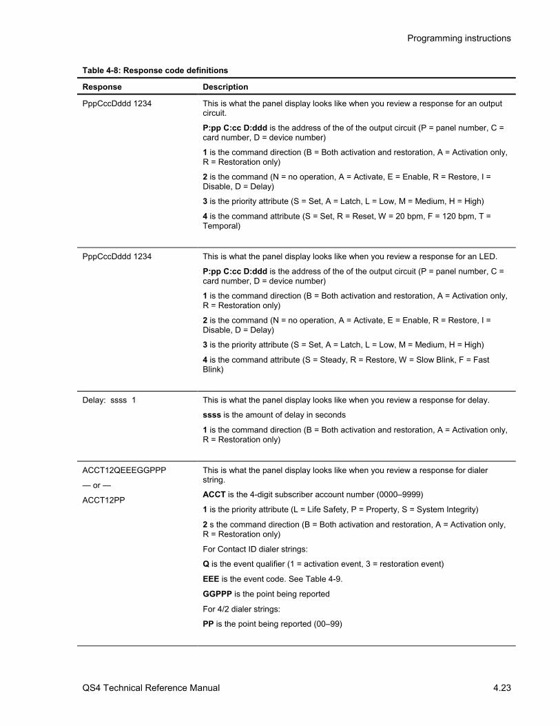
Programming instructions
QS4 Technical Reference Manual 4.23
Table 4-8: Response code definitions
Response Description
PppCccDddd 1234 This is what the panel display looks like when you review a response for an outputcircuit.
P:pp C:cc D:ddd is the address of the of the output circuit (P = panel number, C =card number, D = device number)
1 is the command direction (B = Both activation and restoration, A = Activation only,R = Restoration only)
2 is the command (N = no operation, A = Activate, E = Enable, R = Restore, I =Disable, D = Delay)
3 is the priority attribute (S = Set, A = Latch, L = Low, M = Medium, H = High)
4 is the command attribute (S = Set, R = Reset, W = 20 bpm, F = 120 bpm, T =Temporal)
PppCccDddd 1234 This is what the panel display looks like when you review a response for an LED.
P:pp C:cc D:ddd is the address of the of the output circuit (P = panel number, C =card number, D = device number)
1 is the command direction (B = Both activation and restoration, A = Activation only,R = Restoration only)
2 is the command (N = no operation, A = Activate, E = Enable, R = Restore, I =Disable, D = Delay)
3 is the priority attribute (S = Set, A = Latch, L = Low, M = Medium, H = High)
4 is the command attribute (S = Steady, R = Restore, W = Slow Blink, F = FastBlink)
Delay: ssss 1 This is what the panel display looks like when you review a response for delay.
ssss is the amount of delay in seconds
1 is the command direction (B = Both activation and restoration, A = Activation only,R = Restoration only)
ACCT12QEEEGGPPP
— or —
ACCT12PP
This is what the panel display looks like when you review a response for dialerstring.
ACCT is the 4-digit subscriber account number (0000–9999)
1 is the priority attribute (L = Life Safety, P = Property, S = System Integrity)
2 s the command direction (B = Both activation and restoration, A = Activation only,R = Restoration only)
For Contact ID dialer strings:
Q is the event qualifier (1 = activation event, 3 = restoration event)
EEE is the event code. See Table 4-9.
GGPPP is the point being reported
For 4/2 dialer strings:
PP is the point being reported (00–99)
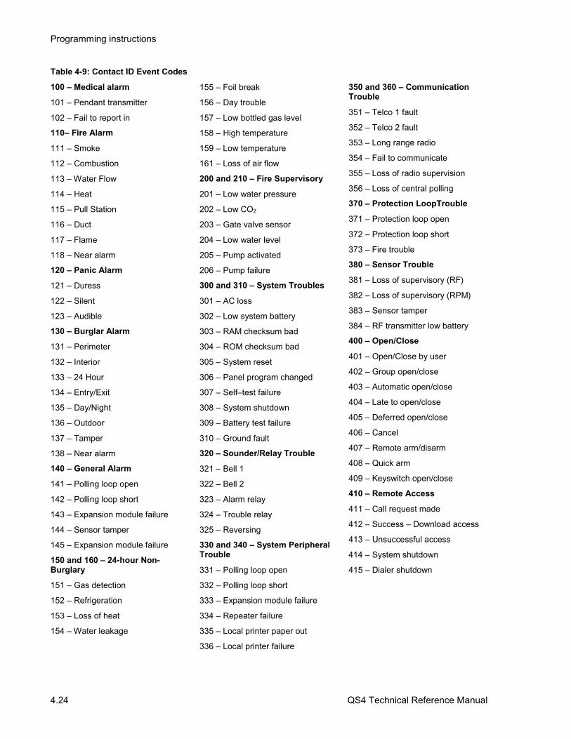
Programming instructions
4.24 QS4 Technical Reference Manual
Table 4-9: Contact ID Event Codes
100 – Medical alarm
101 – Pendant transmitter
102 – Fail to report in
110– Fire Alarm
111 – Smoke
112 – Combustion
113 – Water Flow
114 – Heat
115 – Pull Station
116 – Duct
117 – Flame
118 – Near alarm
120 – Panic Alarm
121 – Duress
122 – Silent
123 – Audible
130 – Burglar Alarm
131 – Perimeter
132 – Interior
133 – 24 Hour
134 – Entry/Exit
135 – Day/Night
136 – Outdoor
137 – Tamper
138 – Near alarm
140 – General Alarm
141 – Polling loop open
142 – Polling loop short
143 – Expansion module failure
144 – Sensor tamper
145 – Expansion module failure
150 and 160 – 24-hour Non-Burglary
151 – Gas detection
152 – Refrigeration
153 – Loss of heat
154 – Water leakage
155 – Foil break
156 – Day trouble
157 – Low bottled gas level
158 – High temperature
159 – Low temperature
161 – Loss of air flow
200 and 210 – Fire Supervisory
201 – Low water pressure
202 – Low CO2
203 – Gate valve sensor
204 – Low water level
205 – Pump activated
206 – Pump failure
300 and 310 – System Troubles
301 – AC loss
302 – Low system battery
303 – RAM checksum bad
304 – ROM checksum bad
305 – System reset
306 – Panel program changed
307 – Self–test failure
308 – System shutdown
309 – Battery test failure
310 – Ground fault
320 – Sounder/Relay Trouble
321 – Bell 1
322 – Bell 2
323 – Alarm relay
324 – Trouble relay
325 – Reversing
330 and 340 – System PeripheralTrouble
331 – Polling loop open
332 – Polling loop short
333 – Expansion module failure
334 – Repeater failure
335 – Local printer paper out
336 – Local printer failure
350 and 360 – CommunicationTrouble
351 – Telco 1 fault
352 – Telco 2 fault
353 – Long range radio
354 – Fail to communicate
355 – Loss of radio supervision
356 – Loss of central polling
370 – Protection LoopTrouble
371 – Protection loop open
372 – Protection loop short
373 – Fire trouble
380 – Sensor Trouble
381 – Loss of supervisory (RF)
382 – Loss of supervisory (RPM)
383 – Sensor tamper
384 – RF transmitter low battery
400 – Open/Close
401 – Open/Close by user
402 – Group open/close
403 – Automatic open/close
404 – Late to open/close
405 – Deferred open/close
406 – Cancel
407 – Remote arm/disarm
408 – Quick arm
409 – Keyswitch open/close
410 – Remote Access
411 – Call request made
412 – Success – Download access
413 – Unsuccessful access
414 – System shutdown
415 – Dialer shutdown

Programming instructions
QS4 Technical Reference Manual 4.25
Table 4-9: Contact ID Event Codes (cont.)
420 – Access Control
421 – Access denied
422 – Access report by user
441 – Stay arming
451 – Early opening/closing
452 – Late opening/closing
453 – Late to open
454 – Late to close
455 – Auto–arm failure
500 and 510 – System Disable
520 – Sounder/Relay Disable
521 – Bell 1 disable
522 – Bell 2 disable
523 – Alarm relay disable
524 – Trouble relay disable
525 – Reversing relay disable
530 and 540 – System PeripheralDisable
550 and 560 – CommunicationDisable
551 – Dialer disable
552 – Radio transmitter
570 – Disable Bypasses
570 – Zone bypass
571 – Fire zone bypass
572 – 24 Hour zone bypass
573 – Burglary zone bypass
574 – Group bypass
600 – Test/Misc.
601 – Manual trigger test
602 – Periodic test report
603 – Periodic RF transmission
604 – Fire test
605 – Status report to follow
606 – Listen–in follow
607 – Walk Test mode
621 – Event Log reset
622 – Event Log 50% full
623 – Event Log 90% full
624 – Event log overflow
625 – Time/Date reset
626 – Time/Date inaccurate
627 – Program mode entry
628 – Program mode exit
631 – Exception schedule change

Programming instructions
4.26 QS4 Technical Reference Manual
Setting up a Zone
Before you begin Before you begin, you should complete a Zone ProgrammingWorksheet (Figure 4-9) for each Zone. Keep a copy for yourrecords. You will also need to refer to the Output Groupprogramming worksheets.
To set up a Zone:1. On the control panel, press Menu.
2. Choose Login then enter the password required for Level 4access.
3. Choose Program > Configure > Zone.
4. To program a new Zone, choose Add, and then choose azone type (Alarm, Supervisory, or Monitor).
— or —
Choose Edit, select an existing zone from the pick list, andthen press Enter.
Configure the Zone 1. Choose Message, scan in the message text, and thenpress Enter.
2. Choose Members, then for each device that comprises theZone:
Choose Device Address, then enter the member's devicenumber from the worksheet
— or —
Choose Enter Serial#, scan in or enter the member's serialnumber.
3. Choose Review to verify which devices you added to theZone. If you added any devices in error, delete them.
4. Choose Output Group > Add, then select the Output groupfrom the pick list that contains the responses you wantactivated, and then press Enter.
Repeat for each Output group you want to add.
5. Choose Review to verify which Output groups you added tothe Zone. If you added any Output groups in error, removethem.
6 For coded systems, choose Coding, and then enter theZone Code.

Programming instructions
QS4 Technical Reference Manual 4.27
Job Name: Page of
Panel: Card: 14
# of CMS receivers: 1 2
CMS phone numbers: Receiver 1: #1) Receiver 1: #2)
Receiver 2: #1) Receiver 2: #2)
Retry Count: 5 6 7 8 9 10
Account Number: Format: 4/2 Contact ID
Test strings: Panel normal: Panel off-normal:
Time: CMS receiver to dial: 1 2
Account Number: Format: 4/2 Contact ID
Test strings: Panel normal: Panel off-normal:
Time: CMS receiver to dial: 1 2
Account Number: Format: 4/2 Contact ID
Test strings: Panel normal: Panel off-normal:
Time: CMS receiver to dial: 1 2
Account Number: Format: 4/2 Contact ID
Test strings: Panel normal: Panel off-normal:
Time: CMS receiver to dial: 1 2
Account Number: Format: 4/2 Contact ID
Test strings: Panel normal: Panel off-normal:
Time: CMS receiver to dial: 1 2
Account Number: Format: 4/2 Contact ID
Test strings: Panel normal: Panel off-normal:
Time: CMS receiver to dial: 1 2
Account Number: Format: 4/2 Contact ID
Test strings: Panel normal: Panel off-normal:
Time: CMS receiver to dial: 1 2
Account Number: Format: 4/2 Contact ID
Test strings: Panel normal: Panel off-normal:
Time: CMS receiver to dial: 1 2
Figure 4-1: DLD Programming Worksheet (sheet 1 of 2)

Programming instructions
4.28 QS4 Technical Reference Manual
Job Name: Page of
Panel: Card: 14
Default Alarm Message: Account Number:
Active Message:
Restore Message:
Default Trouble Message: Account Number:
Active Message:
Restore Message:
Default Supervisory Message: Account Number:
Active Message:
Restore Message:
Figure 4-1 DLD Programming Worksheet (sheet 1 of 2)

Programming instructions
QS4 Technical Reference Manual 4.29
Job Name: Page of
Panel: Card:
001 Device Type:
Text Message: 1)
2)
002 Device Type:
Text Message: 1)
2)
003 Device Type:
Text Message: 1)
2)
004 Device Type:
Text Message: 1)
2)
005 Device Type:
Text Message: 1)
2)
006 Device Type:
Text Message: 1)
2)
007 Device Type:
Text Message: 1)
2)
008 Device Type:
Text Message: 1)
2)
IDC 001
IDC/NAC 004IDC 003IDC 002
IDC 005
IDC/NAC 008
IDC 006IDC 007
Defaults: Alarm for IDC 001 – 003 and IDC 005 – 007,Common Alarm Output for IDC/NAC 004, Visual forIDC/NAC 008
Figure 4-2: ZA8–2 Programming Worksheet

Programming instructions
4.30 QS4 Technical Reference Manual
Job Name: Page of
Panel: Card:
001 Device Type:
Text Message: 1)
2)
002 Device Type:
Text Message: 1)
2)
003 Device Type:
Text Message: 1)
2)
004 Device Type:
Text Message: 1)
2)
005 Device Type:
Text Message: 1)
2)
006 Device Type:
Text Message: 1)
2)
007 Device Type:
Text Message: 1)
2)
008 Device Type:
Text Message: 1)
2)
009 Device Type:
Text Message: 1)
2)
010 Device Type:
Text Message: 1)
2)
011 Device Type:
Text Message: 1)
2)
IDC 001
IDC 003IDC 004
IDC 002
IDC 010
IDC/NAC 013
IDC 011IDC 012
IDC 005
IDC 007IDC 008
IDC 006
IDC 009
IDC/NAC 014IDC/NAC 015IDC/NAC 016
Defaults: Alarm for IDC 001–012, Common AlarmOutput for IDC/NAC 013–014, Visual for IDC/NAC 015–016
012 Device Type:
Text Message: 1)
2)
013 Device Type:
Text Message: 1)
2)
014 Device Type:
Text Message: 1)
2)
015 Device Type:
Text Message: 1)
2)
016 Device Type:
Text Message: 1)
2)
Figure 4-3: ZB16–4 Programming Worksheet

Programming instructions
QS4 Technical Reference Manual 4.31
Job Name: Page of
Panel: Card:
001 NC (normally-closed)
NO (normally-open)
Device type:
002 NC (normally-closed)
NO (normally-open)
Device type:
003 NC (normally-closed)
NO (normally-open)
Device type:
004 NC (normally-closed)
NO (normally-open)
Device type:
005 NC (normally-closed)
NO (normally-open)
Device type:
006 NC (normally-closed)
NO (normally-open)
Device type:
007 NC (normally-closed)
NO (normally-open)
Device type:
008 NC (normally-closed)
NO (normally-open)
Device type:
004
002001
003
005
007008
006
004+ 004–
JP4
008+ 008–
JP8
NC
NO
NC
NO
Figure 4-4: ZA8–2 Programming Worksheet

Programming instructions
4.32 QS4 Technical Reference Manual
Job Name: Page of
Panel:
Card:
NAC 1 device type: Audible Visible NAC 2 device type: Audible Visible
Wiring class: Class A Class B
Number of detector addresses used on loop:
Number of module addresses used on loop:
Card:
NAC 1 device type: Audible Visible NAC 2 device type: Audible Visible
Wiring class: Class A Class B
Number of detector addresses used on loop:
Number of module addresses used on loop:
Card:
NAC 1 device type: Audible Visible NAC 2 device type: Audible Visible
Wiring class: Class A Class B
Number of detector addresses used on loop:
Number of module addresses used on loop:
Card:
NAC 1 device type: Audible Visible NAC 2 device type: Audible Visible
Wiring class: Class A Class B
Number of detector addresses used on loop:
Number of module addresses used on loop:
Figure 4-5: SLIC Programming Worksheet

Programming instructions
QS4 Technical Reference Manual 4.33
Job Name: Page of
Panel: Card:
Model: S/N Device:
Sensitivity: Most More Normal Less Least
Verification: None 12 s 24 s 36 s 60 s
Pre-Alarm: None 20% 40% 60% 80%
Base type: Standard Relay Isolator
Message: 1) 2)
Model: S/N Device:
Sensitivity: Most More Normal Less Least
Verification: None 12 s 24 s 36 s 60 s
Pre-Alarm: None 20% 40% 60% 80%
Base type: Standard Relay Isolator
Message: 1) 2)
Model: S/N Device:
Sensitivity: Most More Normal Less Least
Verification: None 12 s 24 s 36 s 60 s
Pre-Alarm: None 20% 40% 60% 80%
Base type: Standard Relay Isolator
Message: 1) 2)
Model: S/N Device:
Sensitivity: Most More Normal Less Least
Verification: None 12 s 24 s 36 s 60 s
Pre-Alarm: None 20% 40% 60% 80%
Base type: Standard Relay Isolator
Message: 1) 2)
Figure 4-6: Signature Detector Programming Worksheet

Programming instructions
4.34 QS4 Technical Reference Manual
Job Name: Page of
Panel: Card:
Model: S/N Device: 1st) 2nd)
Device #1 Device #2
Device Type: Device Type:
Personality: Personality:
Message: 1) Message: 1)
2) 2)
Model: S/N Device: 1st) 2nd)
Device #1 Device #2
Device Type: Device Type:
Personality: Personality:
Message: 1) Message: 1)
2) 2)
Model: S/N Device: 1st) 2nd)
Device #1 Device #2
Device Type: Device Type:
Personality: Personality:
Message: 1) Message: 1)
2) 2)
Model: S/N Device: 1st) 2nd)
Device #1 Device #2
Device Type: Device Type:
Personality: Personality:
Message: 1) Message: 1)
2) 2)
Figure 4-7: Signature Module Programming Worksheet

Programming instructions
QS4 Technical Reference Manual 4.35
Job Name: Page of
Panel: Output Group:
Response: __ __ __ Type: Active Trouble
Relay Device: __ __ __ __ __ On 20 bpm 120 bpm Temporal
Delay Delay Type: Act and Restoration Activation Restoration Time: __ __ __ __s
Dialer Account No.: __ __ __ __ Send On: Activation Restoration
Priority: Life Safety Property System Integrity
String: (CID) __ __ __ __ __ __ __ __ __ (4/2) __ __
Figure 4-8: Output Group Programming Worksheet

Programming instructions
4.36 QS4 Technical Reference Manual
Job Name: Page of
Panel: Zone:
Zone Type: Alarm Supervisory Monitor
Zone Code:
Message: 1)
2)
Zone Members (32 max):
Output groups (6 max):
Figure 4-9: Zone Programming Worksheet

QS4 Technical Reference Manual 5.1
Chapter 5 Standard applications
SummaryThis chapter provides simplified wiring schematics for standardapplications.
ContentNotification appliance circuits • 5.2Initiating device circuits • 5.5Coded alarm signaling • 5.8Remote station protective signaling system • 5.10Auxiliary protective signaling • 5.12

Standard applications
5.2 QS4 Technical Reference Manual
Notification appliance circuits
SLIC
UL/ULC LISTED10 K EOLRΩ
NAC2 B–
NAC2 B+
NAC2 A+
NAC2 A–
UL/ULC LISTED10 K EOLRΩ
NAC1 B–
NAC1 B+
NAC1 A+
NAC1 A–
Typical Class A NAC circuits
Note: The plus andminus symbolsindicate signalpolarity when theNAC circuit is turnedon.
SLIC
NAC2 B–
NAC2 B+
NAC2 A+
NAC2 A–
UL/ULC LISTED10 K EOLRΩ
NAC1 B–
NAC1 B+
NAC1 A+
NAC1 A–
UL/ULC LISTED10 K EOLRΩ
NOT USED
NOT USED
Typical Class B NAC circuits
Note: The plus andminus symbolsindicate signalpolarity when theNAC circuit is turnedon.

Standard applications
QS4 Technical Reference Manual 5.3
SIGA–CC1
10 9
124 3568 7
SIGA–RM1
124 3568 7
AUX(n)
COM
LOOP B+
LOOP B–
LOOP A+LOOP A–
TO DATA IN TERMINALSON NEXT DEVICE
TO DATA OUT TERMINALSON LAST DEVICE (CLASS A ONLY)
SLIC
PS6
UL/ULC LISTED47 K EOLRΩ
Note: The plus and minus symbols indicate signal polarity when the NAC circuit is turned on.
Typical NAC riser wiring

Standard applications
5.4 QS4 Technical Reference Manual
ZB16–4
UL/ULC LISTED10 K EOLRΩ
Z13–
Z13+
Z15–
Z15+UL/ULC LISTED
10 K EOLRΩ
UL/ULC LISTED10 K EOLRΩ
Z14–
Z14+
Z16–
Z16+UL/ULC LISTED
10 K EOLRΩ
Typical Class B NAC circuits
ZA8–2
UL/ULC LISTED10 K EOLRΩ
ZONE 4 B–
ZONE 4 B+
ZONE 4 A+
ZONE 4 A–
UL/ULC LISTED10 K EOLRΩ
NAC1 B–
NAC1 B+
NAC1 A+
NAC1 A–
Typical Class A NAC circuit

Standard applications
QS4 Technical Reference Manual 5.5
Initiating device circuits
24VDC+24VDC–
LOOP B+
LOOP B–
4 3 2 1
8 7
SIGA–CT1
UL/ULC LISTEDEOL RELAY
UL/ULC LISTED47 K EOLRΩ
LOOP A+LOOP A–
SLIC
PS6
TO DATA OUT TERMINALSON LAST DEVICE (CLASS A ONLY)
TO DATA IN TERMINALSON NEXT DEVICE
JP2ACC PWR
SMK PWR
Typical four-wire smoke detector circuit
TO DATA OUT TERMINALSON LAST DEVICE (CLASS A ONLY)
TODATA IN TERMINALS
ON NEXT DEVICE
LOOP B+
LOOP B–
LOOP A+LOOP A–
SLIC
UL/ULC LISTED22 K EOLRΩ24VDC+
24VDC–
PS6
JP2ACC PWR
SMK PWR SIGA–UM
12345678
91011121314 3-2-1
2–SMK
UL/ULC LISTED15 K EOLRΩ
Typical Class B two-wire smoke detector circuit

Standard applications
5.6 QS4 Technical Reference Manual
TO DATA OUT TERMINALSON LAST DEVICE (CLASS A ONLY)
TODATA IN TERMINALS
ON NEXT DEVICE
LOOP B+
LOOP B–
LOOP A+LOOP A–
SLIC
UL/ULC LISTED22 K EOLRΩ24VDC+
24VDC–
PS6
JP2ACC PWR
SMK PWR SIGA–UM
12345678
91011121314 3-2-1
2–SMK
Typical Class A two-wire smoke detector circuit
Z(n)–UL/ULC LISTED
4.7 K EOLRΩ
ZB16–4
Z(n)+
Typical Conventional Class B IDC circuit
ZONE (n) B–
UL/ULC LISTED4.7 K EOLRΩ
ZA8–2
ZONE (n) B+
ZONE (n) B–
ZONE (n) B+
Typical Conventional Class A IDC circuit

Standard applications
QS4 Technical Reference Manual 5.7
Z(n)+Z(n)–
ZB16–4
24VDC+24VDC–
UL/ULC LISTEDEOL RELAY
UL/ULC LISTED4.7 K EOLRΩ
PS6
JP2ACC PWR
SMK PWR
Typical Conventional Class B four-wire smoke detector circuit
ZONE (n) B+ZONE (n) B–
ZA8–2
24VDC+24VDC–
UL/ULC LISTEDEOL RELAY
UL/ULC LISTED4.7 K EOLRΩ
PS6
JP2ACC PWR
SMK PWR
ZONE (n) A+ZONE (n) A–
Typical Conventional Class A four-wire smoke detector circuit

Standard applications
5.8 QS4 Technical Reference Manual
Coded alarm signaling
1 2 3
1. FACP: Fire alarm control panel with a CPU,PS6, ZB16–4, and standby batteries.
2. MFC–A Accessory Enclosure: Used formounting the remote fire alarm equipment.
3. CDR–3 Bell Coder: Provides coded alarmsignals for 24 Vdc notification appliance circuitsand one of three evacuation signals (temporal, 60bpm, and 90 bpm).
Note: CDR–3 must have firmware version greaterthan 2.0.
Notes• Place the MFC–A and the FACP in the same
room and connect using a section of conduit nogreater than 20 ft in length. Run all wiringbetween cabinets through the conduit.
• Set SW–6 on CDR–3 to ON. Refer to the CDR–3 installation sheet for programminginformation.
• Install a 10 kΩ EOLR across TB2–1 and TB2–2, and TB2–11 and TB2–12 on the CDR–3.
• Set JP2 on the PS6 for ACC PWR
• If the system uses a NAC circuit on an SLIC tooutput the coded signal, program the NACcircuit signal rate as Steady.
• If the system uses the NAC 1 circuit on an SLICto output the coded signal to audible notificationappliances, set JP1 and JP2 on the SLIC toEXT.
Figure 5-1: Typical equipment layout, coded alarm signaling application

Standard applications
QS4 Technical Reference Manual 5.9
10KΩ10KΩ
TB1TB2
JP2JP1
SW1
CDR–3
PS6TB3–3
PS6TB3–1
NAC RISER –
NAC RISER +
PS6TB1–11
PS6TB1–12
PS6TB1–18
PS6TB1–16
Figure 5-2: Coded alarm signaling wiring (coded alarm signal only)
10KΩ10KΩ
TB1TB2
JP2JP1
SW1
CDR–3
PS6TB3–3
PS6TB3–1
PS6TB1–11
PS6TB1–12
PS6TB1–18
PS6TB1–16
NAC RISER –
NAC RISER +
Figure 5-3: Coded alarm signaling wiring (coded signal followed by evacuation signal)

Standard applications
5.10 QS4 Technical Reference Manual
Remote station protective signaling system
1 2 3
1. FACP: Fire alarm control panel with a CPU,PS6, ZB16–4, and standby batteries.
2. MFC–A Accessory Enclosure: Used formounting the remote fire alarm equipment.
3. RPM Reverse Polarity Module: Provides threeindependent reverse polarity signals (alarm,supervisory, trouble) for transmitting system statusto a remote location.
Notes• Place the MFC–A and the FACP in the same
room and connect using a section of conduit nogreater than 20 ft in length. Run all wiringbetween cabinets through the conduit.
• Set JP2 on the PS6 for ACC PWR.
• Install a 3.9 KΩ EOLR across TB1–1 and TB1–2 on the RPM.
Figure 5-4: Typical equipment layout, Remote station protective signaling application

Standard applications
QS4 Technical Reference Manual 5.11
RELAY 1 NO
RELAY 1 C
RELAY 2 C
RELAY 2 NO
RELAY 3 C
RELAY 3 NO
24VDC+
24VDC–
SUPV
ALRM
TRBL
+24V
COM
JP1
ALARM+
TROUBLE+
SUPV+
OFF-SITEMONITORING
RPMPS6
3.9 KΩCITY BOX+
CITY BOX–
ALARM–
TROUBLE–
SUPV–
Note: Plus and minus symbols indicate signal polarity when the circuit is active.
Figure 5-5: Remote station protective signaling wiring

Standard applications
5.12 QS4 Technical Reference Manual
Auxiliary protective signaling
Wire as shown in Figure 5-6. Program the SIGA–CC1 as a common alarm output device. Plus andminus symbols indicate signal polarity with the circuit turned on.
Municipal circuit
Master box
12
1 2
2–CTMSIGA–CC1
10 9
124 3568 7
LOOP B+
LOOP B–
LOOP A+LOOP A–
TO DATA OUT TERMINALSON LAST DEVICE (CLASS A ONLY)
SLIC
TO DATA IN TERMINALSON NEXT DEVICE
24VDC+
24VDC–
LISTED 24VDCSUPPLY
TO NEXT DEVICE
Figure 5-6: Auxiliary protective signaling cabling diagram

QS4 Technical Reference Manual 6.1
Chapter 6 Maintenance instructions
SummaryThis chapter provides instructions for maintaining the system.
ContentPseudo point definitions • 6.2
Table 6-1: Main Panel pseudo points • 6.2Table 6-2: Remote Annunciator pseudo points • 6.2Table 6-3: Power Supply pseudo points • 6.3Table 6-4: SLIC card pseudo points • 6.3Table 6-5: Dialer pseudo points • 6.4Table 6-6: General CPU pseudo points • 6.5
Maintenance tasks • 6.6

Maintenance instructions
6.2 QS4 Technical Reference Manual
Pseudo point definitions
Table 6-1: Main Panel pseudo points
LCD Indication Event Type Definition
Panel xx Card Communications Trouble CPU has failed to communicate with the optioncard at address xx.
Panel 01 Reset Extension Monitor/Trouble Signature loop is still resetting.
Panel 01 Service Active Trouble Trouble Service group was restored with a device still inthe active condition.
Pnl 0x Database Incompatible Trouble Changes made to the system programming on thecontrol panel were not updated in this unit.
Panel 01 Reboot Fault Control panel CPU restarted unexpectedly.
Panel 0x, CH1 Communications Trouble Annunciator is not communicating on RS485channel 1.
Panel 01 Task Failure Trouble Internal processing fault.
Card xx Setup Mismatch Trouble CPU encountered problem configuring the optioncard at address xx.
Dailer Setup Mismatch Trouble A problem has occurred with the CPU configuringthe dialer card.
Power Supply Setup Mismatch Trouble A problem has occurred with the CPU configuringthe POWER supply card.
Panel 01 LED/Switch display Trouble LED/Switch card is not connected.
Panel 0x, CH2 Communications Trouble Annunciator is not communicating on RS485channel 2.
Pnl 01 Database Supervision Trouble Internal CPU memory failure
Panel 01 Code Supervision Trouble Internal CPU memory failure
Panel 01, Call For Service Trouble Internal CPU processing error
Panel 01, ROM Supervision Trouble Internal CPU memory failure
Panel 01 RS232 Port Fault Trouble
Panel 01 Unexpected Card Trouble CPU detected an option card not defined in thedatabase.
Panel 01 Switch Latched Trouble Button either on the main display or on anLED/Switch card has been pressed too long.
Panel 01 Loop Database Fault Trouble Internal CPU memory failure with Signature data.
Table 6-2: Remote Annunciator pseudo points
LCD Indication Event Type Definition
Ann 0x Service Active Trouble Trouble Indicates that a device was left in an activecondition after service group has restored.
Ann 0x Database Incompatible Trouble Indicates that the data
Annunciator 0x Reboot Fault Trouble Indicates CPU has restarted due to internalprocessing failure.

Maintenance instructions
QS4 Technical Reference Manual 6.3
LCD Indication Event Type Definition
Ann 0x, CH1 Communications Trouble Indicates failure to communicate with the mainpanel on RS485 channel 1.
Annunciator 0x Task Failure Trouble Internal software failure
Ann 0x, LED/ Switch Display Trouble Indicates that a SL30-x has been disconnected oris connected but not defined.
Ann 0x, CH2 Communications Trouble Indicates failure to communicate with the mainpanel on RS485 channel 2.
Ann 0x Database Supervision Trouble Internal memory failure
Ann 0x Code Supervision Trouble Internal memory failure
Ann 0x, Call For Service Trouble Internal software failure
Ann 0x ROM Supervision Trouble Internal memory failure
Ann 0x RS232 Port Fault Trouble
Ann 0x Program Mode Trouble Panel has entered program mode.
Ann 0x Switch Latched Trouble Indicates that a button either on the main displayor on an SL30-x has been pressed to long.
Annunciator 0x Power Fault Trouble Indicates a loss of power on either of the 24vdcinputs to the RAI card.
Table 6-3: Power Supply pseudo points
LCD Indication Event Type Definition
Battery Charger Fault Trouble This fault will occur when the battery chargercharging voltage falls below 20.4vdc.
Battery Wiring or Battery Fault Trouble Caused by an open in the battery wiring or if thebatteries are below 20.4vdc.
Aux Power 1/2 Shorted Trouble This point occurs when Aux 1 or Aux 2 power isshorted on the PS6
Aux Power 3 Shorted Trouble This point occurs when Aux 3
Smoke Power Shorted Trouble This point occurs when smoke power is shorted
Primary AC Power Failure Trouble Caused by loss of AC or very low AC.
Excessive Battery Current Trouble Will go active when PS6 detects over currentcondition
Check System Wiring Trouble Indicates a ground fault exists on field wiring.
Power Supply Card RAM Fault Trouble Internal memory fault
Power Supply Card ROM Fault Trouble Internal memory fault
Power Supply EEPROM Fault Trouble Internal memory fault
Table 6-4: SLIC card pseudo points
LCD Indication Event Type Definition
Card 0x, Loop Wiring Problem Trouble Indicates a break on a Class A signature loop
Card 0x Map Fault Trouble Signature map is different than the one written inmemory

Maintenance instructions
6.4 QS4 Technical Reference Manual
LCD Indication Event Type Definition
Card 0x, Mapping In Progress Monitor Indicates Signature devices are in the process ofbeing mapped.
Card 0x Unconfig. Device Trouble Indicates that a new signature device has beendetected on a loop.
Card 0x, Line Initialization Monitor Occurs after power up or a restart. Indicatessignature devices are being initialized.
Card 0x, Loop Ground Fault Trouble Indicates a ground fault on a signature module.
Card 0x, LIM Driver Fault Trouble Internal hardware failure.
Card 0x, RAM Supervision Trouble Internal memory fault
Card 0x, ROM Supervision Trouble Internal memory fault
Card 0x, EEPROM Supervision Trouble Internal memory fault
Table 6-5: Dialer pseudo points
LCD Indication Event Type Definition
Primary Phone Line:check Telco Trouble Telephone line has low or no voltage
Secondary Phone Line:check Telco Trouble Telephone line has low or no voltage
Pri. Receiver Failed to answer Trouble Dialer attempted to dial event to CMS but did notget an answer.
Sec. Receiver Failed to answer Trouble Dialer attempted to dial event to CMS but did notget an answer.
Dialer Account 1 Fault Trouble Indicates dialer did not get proper handshake forevent sent to the CMS for Account 1.
Dialer Account 2 Fault Trouble Indicates dialer did not get proper handshake forevent sent to the CMS for Account 2.
Dialer Account 3 Fault Trouble Indicates dialer did not get proper handshake forevent sent to the CMS for Account 3.
Dialer Account 4 Fault Trouble Indicates dialer did not get proper handshake forevent sent to the CMS for Account 4.
Dialer Account 5 Fault Trouble Indicates dialer did not get proper handshake forevent sent to the CMS for Account 5.
Dialer Account 6 Fault Trouble Indicates dialer did not get proper handshake forevent sent to the CMS for Account 6.
Dialer Account 7 Fault Trouble Indicates dialer did not get proper handshake forevent sent to the CMS for Account 7.
Dialer Account 8 Fault Trouble Indicates dialer did not get proper handshake forevent sent to the CMS for Account 8.
Dialer ROM Fault Trouble Internal memory fault
Dialer Queue Overflow Trouble Indicates that too many dialer messages are tryingto be sent.
Dialer Card, RAM Supervision Trouble Internal memory fault

Maintenance instructions
QS4 Technical Reference Manual 6.5
Table 6-6: General CPU pseudo points
LCD Indication Event Type Definition
Startup Response Monitor Monitor point that goes active on system startup orafter restart.
First Alarm Alarm Occurs anytime that the system goes into alarmfor the first time.
First Supervisory Supervisory Occurs anytime that the system goes intosupervisory for the first time.
First Trouble Trouble Occurs anytime that the system goes into atrouble for the first time.
First Monitor Monitor Occurs anytime that the system goes into amonitor condition for the first time.
Evacuation
Drill Monitor This point will go active anytime drill is pressed.
Alarm Silence Monitor This point will go active anytime alarm silence ispressed.
Two Stage Expiration
Reset Monitor This point goes active anytime reset is pressed.
Reset Phase 1 Monitor Active during the power down phase of reset.
Reset Phase 2 Monitor Active during the retard phase of reset.
Reset Phase 3 Monitor Active during the restoration phase of reset.
First Disable Trouble Activated the first time an item is disabled from thefront menu.
First Test Trouble Activated the first time a service group is startedfrom the front menus.
Two Stage Timer Started
User Trouble Trouble Triggered by custom programming.

Maintenance instructions
6.6 QS4 Technical Reference Manual
Maintenance tasks
What is it you want to do This is how you do it
Change the fuse 1. Switch the circuit breaker that supplies ac power to thecontrol panel to the OFF position.
2. Expose the ac terminal block and pull out the fuse holder.
3. Replace the blown fuse with a new one of the same typeand size.
4. Plug the fuse holder back into the ac terminal block.
5. Switch the circuit breaker that supplies ac power to thecontrol panel to the ON position.
Replacing a SIGA device whenmapping is disabled)
WARNING: Replacing a device when mapping is disabledleaves the area unprotected. The control panel does notautomatically reassign responses to replaced devices whenmapping is disabled.
To replace devices on a loop that operates with mappingdisabled, you must first enable mapping then accept the map.After you replace your devices, you can disable mapping on theloop.
Note: Replacement devices must be the same model as thedevices being replaced.
1. Press Menu.
2. Log onto the panel as a Level 4 operator.
3. Choose Enable > Loop Mapping.
4. Enter the card number of the SLIC that connects to thedevice you want to replace.
Wait until mapping finishes before continuing.
5. Choose Cards > Edit.
6. Enter the card number of the SLIC that connects to thedevice you want to replace.
7. Choose Accept Map.
If actual and expected data for detectors and modules arethe same, press Enter.
8. Choose Exit > Exit > Save and Sync.
9. Replace the device.

QS4 Technical Reference Manual A.1
Appendix A System calculations
SummaryThis appendix provides worksheets for calculating maximum wire lengthsfor notification and Signature circuits, and for sizing standby batteries.
ContentNotification appliance circuit maximum wire length calculation • A.2Signature loop maximum wire length calculations • A.3Battery calculation • A.8

System calculations
A.2 QS4 Technical Reference Manual
Notification appliance circuit maximum wire length calculation
Use this worksheet to determine the maximum wire length of a notification appliance circuit. Fill in oneworksheet for each NAC connected to the panel.
Maximum signal loss allowed 1 1.5 V
× 1000
1500
Wire resistance per 1000 ft/pair 2 ÷ Ω
Total operating current required 3 ÷ A
Maximum wire length ft
Notes
1. For worst case estimates, assume a 1.5 V line loss and all appliances are clustered at theend of the circuit.
2. Use 3.5 for 12 AWG and 2.5 mm2 wire, 5.2 for 14 AWG and 1.5 mm2 wire, 8.0 for 16 AWGand 1.0 mm2 wire, and 13.0 for 18 AWG and 0.75 mm2 wire.
3. Use the filtered 20 Vdc Average Operating Current ratings found on the installation orcatalog sheet of each device.

System calculations
QS4 Technical Reference Manual A.3
Signature loop maximum wire length calculationsUse this worksheet to determine the maximum amount of wire you can use to construct a Signature loop.
Step 1: Calculate the total amount of wire you can used based on the cable manufacturer's capacitanceper foot rating. Total amount of wire shall not exceed the values listed in Table A-1.
500000
Cable capacitance ÷ pF/ft
Total wire ft
Table A-1: Maximum amount of wire you can use to construct a Signature loopWire type 14 AWG / 1.5 mm² 16 AWG / 1.0 mm² 18 AWG / 0.75 mm2
Twisted pair, nonshielded25 pF/36 pF/38 pF
13157 ft(4010 m)
13888 ft(4233 m)
20000 ft(6096 m)
Twisted pair, shielded58 pF/82 pF/84 pF
5952 ft(1814 m)
6098 ft(1859 m)
8621 ft(2628 m)
Nontwisted pair, nonshielded20 pF/20 pF/20 pF
20000 ft(6096 m)
20000 ft(6096 m)
20000 ft(6096 m)
Step 2: Use Table A-2, Table A-3, Table A-4, and Table A-5 to determine the longest allowable circuitpath based on wire size and type, and the number of detector, module, SIGA–UMs or –MABs installed onthe loop.
In the illustration below, the longest circuit path (shown in bold lines) is 1240 ft (377.95 m). The totalamount of wire comprising the loop is 1740 ft (530.35 m)
FACP J
J
10 ft(3.05 m)
200 ft(60.96 m)
30 ft(9.14 m)
J
100 ft(30.48 m)
1000 ft(304.8 m)
200 ft(60.96 m)
200 ft(60.96 m)

System calculations
A.4 QS4 Technical Reference Manual
Table A-2: Longest allowable circuit path with 0 SIGA-UMs or SIGA-MABs configured for 2-wiresmokes
Maximum allowable wire distance using nontwisted, nonshielded wire pairs
18 AWG 16 AWG 14 AWGSignaturedetector
addresses
Signaturemodule
addresses ft m ft m ft m
1–25 0 7437 2267 11815 3601 18792 5728
26–50 0 7038 2145 11180 3408 17782 5420
51–75 0 6638 2023 10545 3214 16772 5112
76–100 0 6238 1901 9910 3021 15762 4804
101–125 0 5839 1780 9275 2827 14752 4497
0 1–25 7267 2215 11544 3519 18361 5597
1–25 1–25 6867 2093 10909 3325 17351 5289
26–50 1–25 6467 1971 10275 3132 16342 4981
51–75 1–25 6068 1849 9640 2938 15332 4673
76–100 1–25 5668 1728 9005 2745 14322 4365
101–125 1–25 5268 1606 8370 2551 13312 4057
0 26–50 6697 2041 10639 3243 16921 5157
1–25 26–50 6297 1919 10004 3049 15911 4850
26–50 26–50 5897 1798 9369 2856 14901 4542
51–75 26–50 5498 1676 8734 2662 13891 4234
76–100 26–50 5098 1554 8099 2469 12881 3926
101–125 26–50 4698 1432 7464 2275 11871 3618
0 51–75 5906 1800 9383 2860 14923 4549
1–25 51–75 5250 1600 8340 2542 13265 4043
26–50 51–75 4633 1412 7360 2243 11707 3568
51–75 51–75 4051 1235 6435 1961 10235 3120
76–100 51–75 3498 1066 5558 1694 8839 2694
101–125 51–75 2973 906 4723 1440 7512 2290
0 76–100 3931 1198 6245 1903 9932 3027
1–25 76–100 3404 1037 5407 1648 8601 2621
26–50 76–100 2899 883 4605 1404 7324 2232
51–75 76–100 2413 735 3833 1168 6096 1858
76–100 76–100 1945 593 3089 942 4913 1498
101–125 76–100 1493 455 2371 723 3771 1149
0 101–125 2631 802 4180 1274 6649 2027
1–25 101–125 2165 660 3439 1048 5470 1667
26–50 101–125 1713 522 2721 829 4328 1319
51–75 101–125 1274 388 2023 617 3218 981
76–100 101–125 847 258 1345 410 2140 652
101–125 101–125 431 131 685 209 1089 332

System calculations
QS4 Technical Reference Manual A.5
Table A-3: Longest allowable circuit path with 1–5 SIGA-UMs or SIGA-MABs configured for 2-wiresmokes
Maximum wire distance using nontwisted, nonshielded wire pairs
18 AWG 16 AWG 14 AWGSignaturedetectoraddresses
Signaturemoduleaddresses ft m ft m ft m
1–25 0 6778 2066 10768 3282 17126 5220
26–50 0 6131 1869 9741 2969 15492 4722
51–75 0 5501 1677 8739 2664 13899 4236
76–100 0 4885 1489 7760 2365 12342 3762
101–125 0 4282 1305 6802 2073 10819 3298
0 1–25 5353 1632 8504 2592 13525 4122
1–25 1–25 4720 1439 7498 2286 11926 3635
26–50 1–25 4100 1250 6513 1985 10359 3157
51–75 1–25 3491 1064 5546 1691 8821 2689
76–100 1–25 2893 882 4597 1401 7311 2228
101–125 1–25 2306 703 3663 1116 5826 1776
0 26–50 3776 1151 5999 1829 9542 2908
1–25 26–50 3153 961 5009 1527 7966 2428
26–50 26–50 2539 774 4034 1230 6416 1956
51–75 26–50 1935 590 3075 937 4890 1491
76–100 26–50 1340 409 2130 649 3387 1032
101–125 26–50 754 230 1197 365 1905 581
0 51–75 2491 759 3957 1206 6293 1918
1–25 51–75 1868 569 2967 904 4720 1439
26–50 51–75 1254 382 1992 607 3168 966
51–75 51–75 648 198 1030 314 1638 499
76–100 51–75 50 15 80 24 126 39
101–125 51–75
0 76–100 1386 422 2201 671 3501 1067
1–25 76–100 760 232 1208 368 1921 586
26–50 76–100 143 44 227 69 361 110
51–75 76–100
76–100 76–100
101–125 76–100
0 101–125
1–25 101–125
26–50 101–125
51–75 101–125
76–100 101–125
101–125 101–125

System calculations
A.6 QS4 Technical Reference Manual
Table A-4: Longest allowable circuit path with 6–10 SIGA-UMs or SIGA-MABs configured for 2-wiresmokes
Maximum wire distance using nontwisted, nonshielded wire pairs
18 AWG 16 AWG 14 AWGSignaturedetectoraddresses
Signaturemoduleaddresses ft m ft m ft m
1–25 0 5045 1538 8015 2443 12748 3886
26–50 0 4494 1370 7139 2176 11355 3461
51–75 0 3950 1204 6275 1913 9981 3042
76–100 0 3414 1040 5423 1653 8625 2629
101–125 0 2884 879 4581 1396 7286 2221
0 1–25 4106 1252 6523 1988 10375 3162
1–25 1–25 3542 1080 5627 1715 8950 2728
26–50 1–25 2985 910 4742 1445 7542 2299
51–75 1–25 2435 742 3868 1179 6152 1875
76–100 1–25 1891 576 3004 916 4778 1456
101–125 1–25 1353 412 2150 655 3419 1042
0 26–50 2869 874 4557 1389 7248 2209
1–25 26–50 2296 700 3648 1112 5802 1768
26–50 26–50 1730 527 2749 838 4372 1332
51–75 26–50 1170 357 1859 567 2957 901
76–100 26–50 617 188 979 299 1558 475
101–125 26–50 68 21 108 33 172 53
0 51–75 1796 547 2853 869 4537 1383
1–25 51–75 1214 370 1929 588 3067 935
26–50 51–75 638 195 1014 309 1613 492
51–75 51–75 69 21 109 33 173 53
76–100 51–75
101–125 51–75
0 76–100 833 254 1323 403 2105 642
1–25 76–100 242 74 385 117 613 187
26–50 76–100
51–75 76–100
76–100 76–100
101–125 76–100
0 101–125
1–25 101–125
26–50 101–125
51–75 101–125
76–100 101–125
101–125 101–125

System calculations
QS4 Technical Reference Manual A.7
Table A-5: Longest allowable circuit path with 11–15 SIGA-UMs or SIGA-MABs configured for 2-wire smokes
Maximum wire distance using nontwisted, nonshielded wire pairs
18 AWG 16 AWG 14 AWGSignaturedetectoraddresses
Signaturemoduleaddresses ft m ft m ft m
1–25 0 3931 1198 6245 1903 9932 3027
26–50 0 3427 1045 5444 1659 8659 2639
51–75 0 2928 892 4651 1418 7397 2255
76–100 0 2432 741 3864 1178 6145 1873
101–125 0 1941 592 3083 940 4903 1495
0 1–25 3247 990 5158 1572 8204 2501
1–25 1–25 2722 830 4324 1318 6878 2096
26–50 1–25 2202 671 3498 1066 5563 1696
51–75 1–25 1686 514 2678 816 4259 1298
76–100 1–25 1174 358 1865 568 2966 904
101–125 1–25 666 203 1058 323 1683 513
0 26–50 2204 672 3502 1067 5570 1698
1–25 26–50 1664 507 2644 806 4205 1282
26–50 26–50 1129 344 1793 547 2852 869
51–75 26–50 598 182 950 289 1511 460
76–100 26–50 71 22 113 34 179 55
101–125 26–50
0 51–75 1263 385 2007 612 3192 973
1–25 51–75 710 216 1128 344 1794 547
26–50 51–75 161 49 256 78 407 124
51–75 51–75
76–100 51–75
101–125 51–75
0 76–100
1–25 76–100
26–50 76–100
51–75 76–100
76–100 76–100
101–125 76–100
0 101–125
1–25 101–125
26–50 101–125
51–75 101–125
76–100 101–125
101–125 101–125

System calculations
A.8 QS4 Technical Reference Manual
Battery calculation worksheetUse this worksheet to determine the amperage capacity of the panel's standby battery. You can obtain operatingcurrent requirements for field devices from their respective installation sheets.
Example: There are 10 strobes rated at 80 mA and 40 mini–horns rated at 10 mA connected to NAC circuitspowered by AUX 1. Enter 1200 mA in the Alarm box for AUX 1.
StandbyCurrent (mA)
AlarmCurrent (mA)
Base Panel (Form A)
SMK/ACC power (FormB)
AUX 1 load [1]
AUX 2 load
AUX 3 load
Loop 1 load
Loop 2 load
Loop 3 load
Loop 4 load
Total Current [2]
× hr × min
÷ 60
+ = mAh
× 1.2
mAh
÷ 1000
Battery size [3] ==== Ah
Notes[1] Maximum 1.5 A per AUX circuit.[2] If the Total Current Required value exceeds 6 A, switch part of the load to an auxiliary power source. The
auxiliary power source must be UL/ULC listed for Fire Protective Signaling Systems.[3] If the calculated battery size exceeds 40 Ah, switch part of the load to an auxiliary power source.

System calculations
QS4 Technical Reference Manual A.9
(A) Base panel current load calculation
Card QtyStandby
Current (mA)Qty ×××× StandbyCurrent (mA)
AlarmCurrent (mA)
Qty ×××× AlarmCurrent (mA)
PS6 1 82 82 100 100
CPU/Display 117 135
SL30 (–1) [1] 1 1
SLIC 33 57
DLD 13 20
ZB16–4 117 152
ZA8–2 73 116
X485 60 60
ZR8 [2] 11 18
Totals [3]
Notes
[1] Add 0.75 mA for each energized LED.
[2] Add 18 mA for each energized relay.
[3] Base panel current must be less than 1.32 mA.
(B) Smoke/Accessory (SMK/ACC) Power current load calculation (max 250 mA)
Card QtyStandby
Current (mA)Qty ×××× StandbyCurrent (mA)
AlarmCurrent (mA)
Qty ×××× AlarmCurrent (mA)
CPU/Display [3] 117 123
SL30 (–1) [1] 1 1
CDR–3 60 100
IOP3A 60 60
RPM [2] 20 20
SIGA-UM, -MAB [4] 2 17 17
Totals
Notes
[1] Add 0.75 mA for each energized LED.
[2] Add 0.7 mA for each output used.
[3] This value includes RAI currents
[4] This represents the smoke power requirements. Only theSIGA–UM or SIGA–MAB that signaled the alarm drawsalarm current. The remaining SIGA–UMs or SIGA–MABsdo not.

System calculations
A.10 QS4 Technical Reference Manual

QS4 Technical Reference Manual B.1
Appendix B Barcode library
SummaryThis appendix contains a set of barcodes that you can use to addlocation messages.
ContentUppercase letters • B.2Numbers and ordinals • B.2Common words • B.3

Barcode library
B.2 QS4 Technical Reference Manual
Uppercase letters
A B C D Backspace
E F G H Delete
I J K L Enter
M N O P
Q R S T
U V W X
Y Z Space
Numbers and ordinals
1 2 3 4 Backspace
5 6 7 8 Delete
9 0 Enter
1ST 2ND 3RD 4TH
5TH 6TH 7TH 8TH
9TH 0TH

Barcode library
QS4 Technical Reference Manual B.3
Common words
ABORT
ABOVE
ALARM
APARTMENT
APT
AREA
ATRIUM
AUDITORIUM
BASEMENT
BELOW
CAFETERIA
CEILING
CLASSROOM
CLOSET
COMPUTER
CONFERENCE
CORRIDOR
DAMPER
DETECTOR

Barcode library
B.4 QS4 Technical Reference Manual
DOOR
DUCT
EAST
ELECTRICAL
ENTRANCE
EXIT
FAN
FAULT
FIRE
FIRE PUMP
FLAME
FLOOR
FOYER
GARAGE
GENERATOR
GYM
HALL
HEAT
HORN
JANITOR

Barcode library
QS4 Technical Reference Manual B.5
KITCHEN
LAB
LEFT
LEVEL
LIBRARY
LOBBY
LOWER
MACHINE
MECHANICAL
MENS
MEZZANINE
MONITOR
NORTH
OFFICE
PARKING
PENTHOUSE
PULL
RELAY
RESTROOM
RIGHT

Barcode library
B.6 QS4 Technical Reference Manual
ROOM
SECURITY
SHAFT
SMOKE
SOUTH
STAGE
STAIRWELL
STOCKROOM
STORAGE
STROBE
SUITE
SUPERVISORY
TROUBLE
UNDER
UPPER
UTILITY
WAREHOUSE
WATERFLOW
WEST
WOMENS

Barcode library
QS4 Technical Reference Manual B.7
ZONE

Barcode library
B.8 QS4 Technical Reference Manual

QS4 Technical Reference Manual C.1
Appendix C SIGA-REL programming
SummaryThis appendix provides information on how to program the SIGA–RELusing the QuickStart Configuration Utility
ContentApplication block diagram • C.2Programming instructions • C.3

SIGA-REL programming
C.2 QS4 Technical Reference Manual
Application block diagram
FACP
SLIC SIGA–APS
RACCR
SIGA–REL
MFC–A
LOOP DATA LOOP DATA24VDC
Minimum system requirements• A QS1 with SLIC card and appropriately sized
standby batteries
• A SIGA–APS mounted in an RACCR enclosurewith appropriately sized standby batteries tosupply 24 Vdc to the SIGA–REL
• A SIGA–REL mounted in an MFC–A enclosure
Caution: You can not have more than 10 SIGA–RELs on one loop.
Related documentationRefer to the SIGA–REL Technical ReferenceManual (P/N 387348) and the latest technicalbulletins for installation and connection information.
Refer to the SIGA–APS installation sheet forinstallation and connection information.
Refer to the RACCR installation sheet forinstallation information.

SIGA-REL programming
QS4 Technical Reference Manual C.3
Programming instructions Read me first WARNING: Attempting to program this application without a
complete understanding of the operation of the SIGA–REL, thelatest technical information, and the consequences of exposingsomeone to fire suppression agents may cause personal injury,event death.
WARNING: Improper application of fire suppression agents canlead to property damage, serious injury, or loss of life. Consultthe applicable NFPA documents and the local authority havingjurisdiction (AHJ) for more information.
WARNING: Disabled and Service Group points will not preventactivation of the release circuits.
This application requires the operation of at least two automaticdetectors to activate the fire suppression system. In order tomeet NFPA 72 requirements, you must program an And groupwith at least two smoke detectors and a minimum activationcount of 2. The smoke detectors must have their Primary andAlternate Verification properties set to None.
The SIGA–REL has six addressable circuits. To add the SIGA–REL to the loop controller database you must add three SIGA–RELs. The first SIGA–REL is for the Abort switch and ManualRelease switch circuits, the second for the two release circuits,and the third for the two prerelease circuits.
Perform these instructions in order from beginning to end.Check the check box provided as you complete each step.
As a safety precaution, disconnect releasing devices fromSIGA–REL TB4 before downloading setup data to the loopcontroller.
Add the Abort and ManualRelease Switch circuits
Note: Enter the information exactly asshown to ensure that you program theapplication according to manufacturer'sspecifications.
1. Click Configure, then click Cabinets.
2. Select the SLIC connected to the SIGA–REL then clickConfigure.
3. Click the Modules tab, then set the Quantity box to 1.
4. Enter the following information:
Device Type: MonitorModel: RELPersonality: (3) Active BMessage Specification: SIGA–REL1 A001 and ABORT SW2nd Device Type: Pull2nd Personality: (1) Alarm B2nd Message Specification: SIGA–REL1 A002 and MANRELEASE SW
5. Click Add.

SIGA-REL programming
C.4 QS4 Technical Reference Manual
Add the the two releasingcircuits
1. Set the Quantity box to 1.
2. Enter the following information:
Device Type: OutputModel: RELPersonality: (16) Output BMessage Specification: SIGA–REL1 A003 and RELEASE1&22nd Device Type: Monitor2nd Personality: (0) None2nd Message Specification: SIGA–REL1 A004 and NOTUSED
3. Click Add.
Add the two prerelease circuits 1. Set the Quantity box to 1.
2. Enter the following information:
Device Type: OutputModel: RELPersonality: (16) Output BMessage Specification: SIGA–REL1 A005 andPRERELEASE 1&22nd Device Type: Monitor2nd Personality: (0) None2nd Message Specification: SIGA–REL1 A006 and NOTUSED
3. Click Add.
This is how your entries in the Modules table should look. Your addresses may be different.
Address Serial Number Device Type Model Text 1 Text 2 Personality
126 Monitor REL SIGA–REL1 A001 ABORT SW (3) Active B
127 Pull REL SIGA–REL1 A002 MAN RELEASE SW (1) Alarm B
128 Output REL SIGA–REL1 A003 RELEASE 1&2 (16) Output B
129 Monitor REL SIGA–REL1 A004 NOT USED (0) None
130 Output REL SIGA–REL1 A005 PRERELEASE 1&2 (16) Output B
132 Monitor REL SIGA–REL1 A006 NOT USED (0) None

SIGA-REL programming
QS4 Technical Reference Manual C.5
Create a response that activatesthe prerelease circuits when anyone detector in the protectedarea signals an alarm
1. Click Configure > Correlations
2. Click the Zones tab, then click Add Zones.
3. Click the Members tab, then click Add Device.
4. Select only the devices required to activate the SIGA–RELprerelease circuits then click OK.
5. Click the Responses tab, click the Response Type arrow,and then select Active.
6. Click Outputs, select the device labeled SIGA REL1 A005PRERELEASE 1&2, and then click OK.
Create a response that activatesthe release circuits when two ormore detectors in the protectedarea signal an alarm
Note: To comply with NFPA 72, youmust program an And Group with atleast two smoke detectors and aminimum activation count of 2. Thesmoke detectors must have theirPrimary and Alternate Verificationproperties set to None (verified smokedetectors not allowed).
1. Click the And Groups tab, then click Add AND Group.
2. Set the Activation Count box for 2.
3. Click the Members tab, then click Add Device.
4. Select only the detectors required to activate the SIGA–REL release circuits then click OK.
5. Click the Responses tab, click the Response Type arrow,and then select Active.
6. Click Delays
7. In the Delay On list, click Activation and Restoration.
8. Set the Seconds box to 10.
9. Click Outputs, select the device labeled SIGA REL1 A003RELEASE 1&2, and then click OK.
Create a response that activatesthe release circuits when someonepresses the manual release switch
1. Click the Devices tab, then select the circuit labeledSIGA–REL A002 MAN RELEASE SW.
2. Click the Responses tab, click the Response Type arrow,and then select Active.
3. Click Outputs, then:
Hold the Ctrl key down
Select the device labeled SIGA REL1 A005 Prerelease1&2
Select the device labeled SIGA REL1 A003 Release 1&2
Release the Ctrl key then click OK.
Note: The prerelease circuit must appear before the releasingcircuit in the response list.

SIGA-REL programming
C.6 QS4 Technical Reference Manual
Create a response that activatesthe prerelease circuits whensomeone presses the Drill switchNote: Create this response only ifrequired. Pressing Drill will activate theprerelease circuits but pressing Drill asecond time will not restore theprerelease circuits. You must pressReset to silence the prerelease circuits.
1. Click the Devices tab then select the Show Pseudo Pointscheck box.
2. Select the circuit labeled Drill (address 007).
3. Click the Responses tab, click the Response Type arrow,and then select Active.
4. Click Outputs, select the device labeled SIGA REL1 A005PRERELEASE 1&2, and then click OK.
Retrieve the loop data from theSLIC
1. Click Configure, then click Cabinets.
2. Select the SLIC connected to the SIGA–REL then clickConfigure.
3. Set the Communications Port setting for the COM port usedto connect the service computer to the control panel.
4. Click Retrieve Signature Data
5. After the upload has finished, click OK.
Reconcile the actual andexpected data
Caution: Clicking Accept Actual willenter the selected device into thedatabase with its current programmedparameters. This will corrupt thedatabase if you have already enteredthe device.
1. Click the Mapping tab, then click Model.
2. Look for a string of at least six RELs marked with redbackgrounds and double-click the first REL in the string.
3. If the serial number displayed in the Module Propertiesdialog is not the same as the serial number shown on thebar code attached to the SIGA–REL, click Close, and thendouble-click the next REL in the string.
4. If the serial numbers are the same:
Click Select Expected.
In the Module Selection dialog, select the row that has theREL with the Monitor device type and marked SIGA–REL1A001 Abort SW, then click OK.
Click Close.
5. Select the next REL then click Select Expected.
In the Module Selection dialog, select the row that has theREL with the Output device type and marked SIGA–REL1A003 Release 1&2, then click OK.
Click Close.
6. Select the next REL then click Select Expected.
In the Module Selection dialog, select the row that has theREL with the Output device type and marked SIGA–REL1A005 Prerelease 1&2, then click OK.
Click Close.

SIGA-REL programming
QS4 Technical Reference Manual C.7
Send the reconciled data to theloop controller
Click the Controller tab, then click Send Signature Data.

SIGA-REL programming
C.8 QS4 Technical Reference Manual