Technical Reference - rainwaterautomation.com · Figure 9 shows the wiring for the 24VAC...
15
Technical Reference This document covers the main features, options, configuration and wiring for the Rainwater Automation controller. Feb 2018 Better Water, Less Maintenance
Transcript of Technical Reference - rainwaterautomation.com · Figure 9 shows the wiring for the 24VAC...
Technical Reference This document covers the main features, options, configuration and wiring for the Rainwater Automation controller. Feb 2018 Better Water, Less Maintenance

Technical Reference S2 © 2018 www.RainwaterAutomation.com Page 2
Contents Overview ....................................................................................................................................................... 3 Getting Started ............................................................................................................................................. 4
Wiring Overview ................................................................................................................................... 5 Cable Preparation ................................................................................................................................. 5
Rain Sensor Wiring ....................................................................................................................................... 6 Flush Valve Wiring ........................................................................................................................................ 7 Stage System Wiring ..................................................................................................................................... 8 Stage Pump Control ...................................................................................................................................... 9 Expansion Box / Remote Display ................................................................................................................ 10 System Configuration ................................................................................................................................. 11
Control Menu.......................................................................................................................................... 11 Flush Configuration ................................................................................................................................ 11 Stage Configuration ................................................................................................................................ 12 User Preferences .................................................................................................................................... 12 Miscellaneous ......................................................................................................................................... 12
Test Mode ................................................................................................................................................... 13 Testing the Flush Automation ............................................................................................................ 14 Testing the Stage Pump ...................................................................................................................... 14
Appendix ..................................................................................................................................................... 15
Figures FIGURE 1 - T568 COLOR CODE 4 FIGURE 2 - SIMPLE, PASSIVE SYSTEM 4 FIGURE 3 –LARGER, ACTIVE SYSTEM 4 FIGURE 4 - JACK LOCATIONS ON MAIN BOARD 5 FIGURE 5 - RJ-45 PLUG 5 FIGURE 6 - RG-11 RAIN SENSOR WIRING 6 FIGURE 7 - RG-11 TO EXP BOX 6 FIGURE 8 – RAIN SENSOR TO TERMINAL STRIP 6 FIGURE 9 – ACTUATOR WIRING 7 FIGURE 10 - TEMPERATURE SENSOR 7 FIGURE 11 - EXPANSION BOX WIRING 8 FIGURE 12 - STAGE PUMP CONTROL WIRING 9 FIGURE 13 - 110V PUMP WIRING 9
Rainwater Collection System Controller U.S. Patent 9,633,532 Apr 2017
Technical Reference S2 © 2018 www.RainwaterAutomation.com Page 3
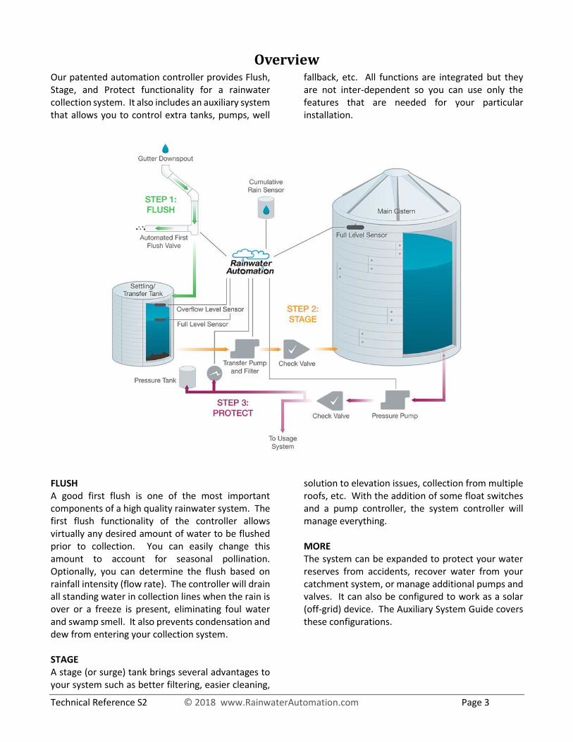
Overview Our patented automation controller provides Flush, Stage, and Protect functionality for a rainwater collection system. It also includes an auxiliary system that allows you to control extra tanks, pumps, well
fallback, etc. All functions are integrated but they are not inter-dependent so you can use only the features that are needed for your particular installation.
FLUSH A good first flush is one of the most important components of a high quality rainwater system. The first flush functionality of the controller allows virtually any desired amount of water to be flushed prior to collection. You can easily change this amount to account for seasonal pollination. Optionally, you can determine the flush based on rainfall intensity (flow rate). The controller will drain all standing water in collection lines when the rain is over or a freeze is present, eliminating foul water and swamp smell. It also prevents condensation and dew from entering your collection system. STAGE A stage (or surge) tank brings several advantages to your system such as better filtering, easier cleaning,
solution to elevation issues, collection from multiple roofs, etc. With the addition of some float switches and a pump controller, the system controller will manage everything. MORE The system can be expanded to protect your water reserves from accidents, recover water from your catchment system, or manage additional pumps and valves. It can also be configured to work as a solar (off-grid) device. The Auxiliary System Guide covers these configurations.
Technical Reference S2 © 2018 www.RainwaterAutomation.com Page 4
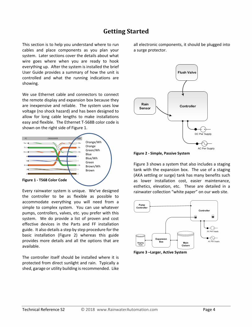
Getting Started This section is to help you understand where to run cables and place components as you plan your system. Later sections cover the details about what wire goes where when you are ready to hook everything up. After the system is installed the brief User Guide provides a summary of how the unit is controlled and what the running indications are showing. We use Ethernet cable and connectors to connect the remote display and expansion box because they are inexpensive and reliable. The system uses low voltage (no shock hazard) and has been designed to allow for long cable lengths to make installations easy and flexible. The Ethernet T-568B color code is shown on the right side of Figure 1.
Orange/Wh Orange Green/Wh Blue Blue/Wh Green Brown/Wh Brown
Figure 1 - T568 Color Code
Every rainwater system is unique. We’ve designed the controller to be as flexible as possible to accommodate everything you will need from a simple to complex system. You can use whatever pumps, controllers, valves, etc. you prefer with this system. We do provide a list of proven and cost effective devices in the Parts and FF installation guide. It also details a step by step procedure for the basic installation (Figure 2) whereas this guide provides more details and all the options that are available. The controller itself should be installed where it is protected from direct sunlight and rain. Typically a shed, garage or utility building is recommended. Like
all electronic components, it should be plugged into a surge protector.
Controller
AC Pwr Supply
DC Pwr Supply
Flush Valve
Rain
Sensor
Figure 2 - Simple, Passive System
Figure 3 shows a system that also includes a staging tank with the expansion box. The use of a staging (AKA settling or surge) tank has many benefits such as lower installation cost, easier maintenance, esthetics, elevation, etc. These are detailed in a rainwater collection “white paper” on our web site.
Controller
AC Pwr Supply
DC Pwr Supply
Expansion
BoxStaging
Tank
Pump
Controller
Main
Cistern
Figure 3 –Larger, Active System

Technical Reference S2 © 2018 www.RainwaterAutomation.com Page 5
Wiring Overview The control board is shown in Figure 4. The input and remote display use RG-45 jacks. The specifics of your installation will determine which jacks and terminals you will use. This guide will walk you through the options.
Input JackRain sensor -or-
Expansion Box
InterconnectPin 1
DC Power
Jack
Remote
Display Jack
Freeze
Sensor
Selector
Flush Valve(extended cable)
Flush Valve (factory cable)
Stage &
Auxiliary
Terminal
AC Power
Terminal
Figure 4 - Jack Locations on Main Board
Cable Preparation
When attaching a plug to direct burial cable, you may want to extend the wires from the sheath (as shown) to make bending the cable easier. The system is not using Ethernet protocol so this is acceptable. Follow the color code from Figure 1. As pictured here, pin 1 is on the left. Push wires fully into plug and crimp with RJ-45 tool. Figure 5 - RJ-45 Plug
All outdoor cable should be rated for direct burial. If you have lots of rocks we recommend some protection for the cable (conduit). You might want to consider running a spare cable while the trench is open. The cable may have gel to keep it sealed and pliable so have some tissue when you’re making connections to wipe this off as it’s really sticky. Now that we’ve covered the high level concepts, the following sections will get into the details of exactly what wire goes where to make the final connections.

Technical Reference S2 © 2018 www.RainwaterAutomation.com Page 6
Rain Sensor Wiring The rain sensor is the key to the automation system. We use the RG-11 rain sensor which is a wired device so there are no batteries to replace. Since it’s a sealed device there are no problems with bugs or debris causing it to fail. Generally, you want the rain sensor to be mounted with a clear view to the sky, but low enough to access for testing. Figure 6 shows the wiring internal to the rain sensor using colors from an Ethernet cable for pins 1, 2 & 4.
Figure 6 - RG-11 Rain Sensor Wiring
If you are not using a remote display or expansion box you can plug the Ethernet cable into either the input or remote jack on the controller. If you are using a remote display or an expansion box, connect the rain sensor as shown in Figure 7.
Figure 7 - RG-11 to Exp Box
You can alternatively connect the rain sensor directly to the input terminal strip on the control board as shown in Figure 8.
Figure 8 – Rain Sensor to Terminal Strip

Technical Reference S2 © 2018 www.RainwaterAutomation.com Page 7
Flush Valve Wiring Figure 9 shows the wiring for the 24VAC transformer and the valve actuator. If the controller is close enough for the activator cable to reach, you can just plug the cable into the header pins. Otherwise, make an appropriate water tight splice to the activator cable and connect to the actuator terminals. Once you have made these connections you can set the cam switches in the activator to properly position the Jandy valve. It’s easier to do this prior to plumbing the valve in. You’ll need to plug in both power supplies and use the “power activator” feature of the Test Mode to perform this alignment.
- or -
Figure 9 – Actuator Wiring Once you have completed the activator alignment and plumbed the Jandy valve into the flush line, you have completed the first flush installation. Use the procedure in the Test Mode section of the manual to verify your first flush installation is working correctly.
Installing a Remote Display This is an optional feature. A remote display is created by plugging an expansion box into the display jack of the controller. You should consider a remote display if:
1. The owner wants a visual status display to mirror the indications on the button panel. This is recommended for systems that use pumps.
2. The controller is mounted indoors so the internal temperature sensor will not detect a freeze. Change the jumper J2 (located just below the cable that connects to the front panel) to center & left pins.
Figure 10 - Temperature Sensor

Technical Reference S2 © 2018 www.RainwaterAutomation.com Page 8
Stage System Wiring The Expansion Box / Remote Display makes integrating a staging tank in your system easy to implement. Wiring for the float switches is depicted in Figure 11. We recommend mounting the box on the staging tank near the upper bulkhead. If you use screws, use only stainless steel and penetrate above the overflow level. Stage Tank - Pump Start Switch (red LED): A float switch should be installed in the staging tank at whatever level you want the pump to start running. General guidance would be as low as possible that still allows the leads from the switch to reach into the expansion box for connecting (so you don’t have to make splices). The staging pump will run as long as this switch is closed and for an additional time set by the “stage pump run minutes” configuration after water falls below the switch (default is 1 minute).
Stage Tank – Stage Full Switch (green LED): This float switch should be located so it closes when the water level would be just below upper bulkhead. It allows the controller to manage the flush valve to prevent flooding from the staging tank during torrential rain. When your main cistern fills, the controller will fill to this switch before opening the flush valve. It also serves as a back-up to the pump start switch should it fail. Main Cistern – Cistern Full Switch (blue LED): The main cistern full switch will tell the system to stop running the staging pumps, fill the staging tank, then flush everything else. To use this power saving option, you’ll need to run a cable from the main cistern to the expansion box. If you decide to not install this switch, the staging approach will still work but the pump will continue to move water to the main cistern and you’ll have to manage any overflow there. This float switch should be installed such that it closes just before water would overflow from the main cistern.
Cistern
Staging
Tank
Figure 11 - Expansion Box Wiring

Technical Reference S2 © 2018 www.RainwaterAutomation.com Page 9
Stage Pump Control The controller is designed to be independent of the horsepower, voltage or current ratings of the pump you have selected. It provides control signals that interface to a pump control relay suitable for the selected pump. Figure 12 shows control wiring for a stage pump.
Pump Controller
Figure 12 - Stage pump control wiring
If your pump comes with a plug (most 120v pumps do), you can modify a 12 gauge extension cord for it to plug into. Measure the distance to the nearest suitable outlet and cut the cord so the plug end reaches between the pump controller and outlet. Measure the socket end of the cord to reach from the controller to the pump cord. Bring both cut ends into the controller using an appropriate strain relief (Romex connector or cable gland). The controller should be mounted as close as possible between the pump and the power outlet to minimize the cord length. It should not be mounted closer than 2 ft from the rainwater controller.
Connect the green wires from the cord to the grounding lug on the controller box. The black and white wires from the plug end of the cord goes to the L1 and L2 lugs of the relay, the black and white wires from the socket end goes to the T1 and T2 lugs of the relay (see Figure 13). This technique generally does not require the services of an electrician. However, you may want to consider an electrician in the following cases:
You are not comfortable with this wiring Local code ordinances You need to have an outlet installed in the
vicinity of your pump You prefer to have the electrical wired
directly into the pump controller You are using a 220V pump
Figure 13 - 110V pump wiring

Technical Reference S2 © 2018 www.RainwaterAutomation.com Page 10
Expansion Box / Remote Display There is no hardware difference between the expansion box and the remote display. The function is determined by which jack you plug it into. If it is plugged into the input jack, it is an expansion box as it expands the inputs out to the tanks. If you plug it into the remote display jack it mirrors the indications on the panel to a location more easily viewed by the owner. Both applications will likely find the box exposed to the elements so we do not pre-drill any holes in the box. This allows you to find the best way to keep the box water tight. If you are wiring a remote display and connecting the rain sensor elsewhere, you may want to make the hole just big enough for a single cable and not use a gland:
The next step whether using a gland or not is to plug the cable into the jack, then mount the PCB:
Be sure to seal around the cable with silicone. If you will be using the box for expansion to float switches, you will have multiple cables and/or wires coming into it. Use an appropriately sized cable gland and when finished wiring use some plumber’s putty in the gland then tighten it down to make a seal. Don’t use silicone in the gland as this would make any future service (e.g. replacing a bad float switch) very difficult.
Remember: The key purpose of the box is to protect the wiring connections from the elements. Water and bugs are the enemy of electrical connections so it is essential that they are not allowed to penetrate this box when you are finished.

Technical Reference S2 © 2018 www.RainwaterAutomation.com Page 11
System Configuration # Menu Button Parameter Default Max Site
1 Control Menu
Flush Additional Flush for Drought 2 3
Hold DC Power Control 1 4
Cycle Freeze Protection 1 3
2 Flush Configuration
Flush Flush when Full Behavior 1 4
Hold 3rd Port Used 1 2
Cycle Flush Method 1 3
3 Stage Configuration
Flush
Hold Stage Pump Run Limit (x15) 2 17
Cycle Stage Pump Run Min 1 254
4 User Preferences
Flush Contractor Lock 1 2
Hold Mist Filter 3 5
Cycle Verbose Level 2 7
6 Miscellaneous
Note: menu 5 and other green parameters are covered in Aux System Guide
Hold Actuator Cycle Time 5 15
To enter a configuration menu, press the Reset button then hold down the Flush button while counting blinks on the Value LED. Release the button after the number of blinks corresponds to the menu number you want. You will see the Active LED flickering. Every few seconds it will stop flickering and blink the menu number.
All configuration options use a brief button press to show the current value. If you press and hold you will be entering a new value. The default values are appropriate for the vast majority of systems. Press the Reset button to exit a configuration menu. If your controller has a button labeled “Pump” instead of “Cycle”, use it wherever the Cycle button is called out.
Control Menu Additional Flush (Flush Button) During long stretches without rain the roof collects more debris. This setting adds to the flush to compensate for drought conditions. 1 - Extra flush for every 10 days of drought 2 - Extra flush for every 20 days of drought 3 - Extra flush for every 30 days of drought Freeze Protection (Cycle Button) The system will detect a freeze and stop collection automatically. This protects all of your flush and collection lines. If the weather is expected to be hovering above and below freezing you have 2 options. If you lock freeze mode, the system will stay
in flush mode until the temperature reaches about 50 before it switches back to automatic. If you disable freeze detection the system will continue to function as usual regardless of the temperature.
1 – Automatic (open flush during freeze)
2 - Lock the system in freeze mode
3 - Disable freeze detection
Flush Configuration Flush Mode (Flush Button)
This setting determines what the flush valve does
when the main cistern is full. You must install a float
switch in the main cistern for this to work. If you do
not have a staging tank, do not use options 1 or 4. If
Technical Reference S2 © 2018 www.RainwaterAutomation.com Page 12
you do not use any float switches, the system will
function as option 3.
1 - Continue collecting until water in the main staging
tank reaches the Full switch, and then open the flush
valve.
2 - Open the flush valve when the cistern is full.
3 - Continue collecting when the cistern is full.
4 - Continue collecting until water in the main staging
tank reaches the Start switch, and then open the
flush valve.
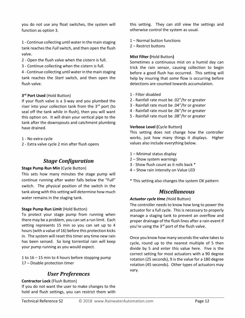
3rd Port Used (Hold Button) If your flush valve is a 3-way and you plumbed the riser into your collection tank from the 3rd port (to seal off the tank while in flush), then you will want this option on. It will drain your vertical pipe to the tank after the downspouts and catchment plumbing have drained. 1 - No extra cycle 2 - Extra valve cycle 2 min after flush opens
Stage Configuration Stage Pump Run Min (Cycle Button)
This sets how many minutes the stage pump will
continue running after water falls below the “Full”
switch. The physical position of the switch in the
tank along with this setting will determine how much
water remains in the staging tank.
Stage Pump Run Limit (Hold Button) To protect your stage pump from running when there may be a problem, you can set a run limit. Each setting represents 15 min so you can set up to 4 hours (with a value of 16) before this protection kicks in. The system will reset this timer any time new rain has been sensed. So long torrential rain will keep your pump running as you would expect. 1 to 16 – 15 min to 4 hours before stopping pump 17 – Disable protection timer
User Preferences Contractor Lock (Flush Button) If you do not want the user to make changes to the hold and flush settings, you can restrict them with
this setting. They can still view the settings and otherwise control the system as usual. 1 – Normal button functions 2 – Restrict buttons Mist Filter (Hold Button) Sometimes a continuous mist on a humid day can trick the rain sensor, causing collection to begin before a good flush has occurred. This setting will help by insuring that some flow is occurring before detections are counted towards accumulation. 1 - Filter disabled 2 - Rainfall rate must be .02”/hr or greater 3 - Rainfall rate must be .04”/hr or greater 4 - Rainfall rate must be .06”/hr or greater 5 - Rainfall rate must be .08”/hr or greater Verbose Level (Cycle Button) This setting does not change how the controller works, just how many things it displays. Higher values also include everything below. 1 – Minimal status display 2 – Show system warnings 3 - Show flush count as it rolls back * 4 – Show rain intensity on Value LED * This setting also changes the system OK pattern
Miscellaneous Actuator cycle time (Hold Button)
The controller needs to know how long to power the actuator for a full cycle. This is necessary to properly manage a staging tank to prevent an overflow and proper drainage of the flush lines after a rain event if you’re using the 3rd port of the flush valve.
Once you know how many seconds the valve takes to cycle, round up to the nearest multiple of 5 then divide by 5 and enter this value here. Five is the correct setting for most actuators with a 90 degree rotation (25 seconds), 9 is the value for a 180 degree rotation (45 seconds). Other types of actuators may vary.
Technical Reference S2 © 2018 www.RainwaterAutomation.com Page 13
Test Mode Test mode helps you to verify that everything is connected and working correctly. You can use this to verify your installation or troubleshoot problems should it be necessary. To put the system into test mode, press the Reset button then immediately press the Hold button until the Active indicator flickers. The system will remain in test mode until you press the Reset button. It defaults to the input test mode (nothing will show unless a switch is closed).
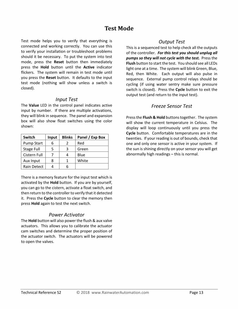
Input Test The Value LED in the control panel indicates active input by number. If there are multiple activations, they will blink in sequence. The panel and expansion box will also show float switches using the color shown:
Switch Input Blinks Panel / Exp Box
Pump Start 6 2 Red
Stage Full 5 3 Green
Cistern Full 7 4 Blue
Aux Input 8 1 White
Rain Detect 4 6 There is a memory feature for the input test which is activated by the Hold button. If you are by yourself, you can go to the cistern, activate a float switch, and then return to the controller to verify that it detected it. Press the Cycle button to clear the memory then press Hold again to test the next switch.
Power Activator The Hold button will also power the flush & aux valve actuators. This allows you to calibrate the actuator cam switches and determine the proper position of the actuator switch. The actuators will be powered to open the valves.
Output Test This is a sequenced test to help check all the outputs of the controller. For this test you should unplug all pumps so they will not cycle with the test. Press the Flush button to start the test. You should see all LEDs light one at a time. The system will blink Green, Blue, Red, then White. Each output will also pulse in sequence. External pump control relays should be cycling (if using water sentry make sure pressure switch is closed). Press the Cycle button to exit the output test (and return to the input test).
Freeze Sensor Test
Press the Flush & Hold buttons together. The system will show the current temperature in Celsius. The display will loop continuously until you press the Cycle button. Comfortable temperatures are in the twenties. If your reading is out of bounds, check that one and only one sensor is active in your system. If the sun is shining directly on your sensor you will get abnormally high readings – this is normal.
Technical Reference S2 © 2018 www.RainwaterAutomation.com Page 14
Testing the Flush Automation
Startup: Press Reset. The controller should blink some start codes then position the actuator. During operation of the flush valve the Active LED will be lit and the green “Flush” LED will be glowing up and down. If the Value LED is lit, the valve is closing, otherwise it is opening.
Force Collection: Briefly press the Flush and Hold buttons together. The actuator should move the valve to the closed or collect position.
Force Flush (clear all): Press the Flush and Hold buttons together until the Active LED starts flashing. The actuator should move the valve to the flush position. If your results are the opposite, reverse the position of the switch on the actuator. This button combination is a full system reset (the Reset button will restart the system but keep all accumulation values). Drip Test: Starting from the flush position, use the supplied eyedropper to drip water over the top of the rain sensor. It will take several seconds of dripping for the sensor to activate. You’ll hear it click and if you are looking down into the top, you’ll see a brief green blink. On the second detection, the controller’s display should change to a series of blinks on the green LED. Continue dripping water on the sensor. With each detection you should see fewer green blinks. After your flush setting has been reached the valve should close. When the valve is closed the Green LED will be lit.
Testing the Stage Pump
Press the Cycle button, the pump should start and run for the duration of the stage pump run min setting (see Stage Configuration). The pump will also run if you lift the start switch in the staging tank (you might have to lift it twice if you have manually stopped the pump with the button.
It would not be unusual for the system to reflect error codes following manual lifting of switches. These can be ignored. Press Reset when finished testing.

Technical Reference S2 © 2018 www.RainwaterAutomation.com Page 15
AppendixWarranty: The automation controller is warranted for 1 year. A replacement for the defective part will be sent in exchange. Warranty coverage is for parts only. Installation: Your electrician is responsible for following all applicable wiring codes on the pump wiring to insure a safe installation. Your plumber should follow the plumbing tips we have posted on our web site as well as any local plumbing codes that apply to rain water collection. Application Warning: You should always take into account worst case scenarios of torrential downpours during a power outage. If your cisterns are outside you may have less to worry about, but if you have them housed in a building you would want to make sure that water always has a controlled way to exit without creating any flooding issues. Disclaimer: It is the responsibility of the system designer and purchaser of the Flush Controller to insure that a failure of the Flush Controller will not cause consequential damages. If a failure in Flush Controller or any part of the associated system would cause any potential disaster, we recommend against deployment of the Flush Controller. It is the responsibility of the system designer and purchaser of the Flush Controller to be aware of performance limitations of the device and system using the device. Under no circumstances will Rainwater Automation Systems be held responsible for any damages created by a system in which the device was used. If a potential purchaser of the Flush Controller does not agree with these terms, we ask that you not buy the Flush Controller. Deployment of the Flush Controller implies understanding and agreeing to these limits of liability.