TECHNICAL PRODUCT DATASHEET - Nexcess CDN algorithms are optimized to take advantage of the J1939...
46
ISO 9001 CERTIFIED 607 NW 27th Ave Ocala, FL 34475 Phone: (352) 629-5020 or 800-533-3569 Fax: (352)-629-2902 SUITABLE FOR EXTERNAL DISTRIBUTION TECHNICAL PRODUCT DATASHEET Total Pressure Governor Plus TPG+ P/N 118710 FORM-ENG-0018 REV A 06-02-03
-
Upload
vuongnguyet -
Category
Documents
-
view
215 -
download
0
Transcript of TECHNICAL PRODUCT DATASHEET - Nexcess CDN algorithms are optimized to take advantage of the J1939...

ISO 9001 CERTIFIED
607 NW 27th Ave Ocala, FL 34475
Phone: (352) 629-5020 or 800-533-3569 Fax: (352)-629-2902
SUITABLE FOR EXTERNAL DISTRIBUTION
TECHNICAL PRODUCT DATASHEET
Total Pressure Governor Plus TPG+
P/N 118710
FORM-ENG-0018 REV A 06-02-03
FORM-ENG-0018 REV A 05-27-03
607 NW 27th Ave Ocala, FL 34475
Ph: 352-629-5020 or 1-800-533-3569 Fax : 352-629-2902 or 1-800-520-3473
TECHNICAL DATA SHEET PAGE 1 OF 45
DATE 9/12/2016
PRODUCT GROUP THROTTLE CONTROL P/N 118710 REV 2.02
PRODUCT TOTAL PRESSURE GOVERNOR PLUS (TPG+) BY AMS/GMC
Manual P/N 118711
1. REVISION LOG ........................................................................................................................................... 3
2. SYSTEM OVERVIEW .................................................................................................................................. 4
2.1. SYSTEM PART NUMBERS ........................................................................................................................... 4 2.2. HARNESS DETAIL (P/N 118453 AND P/N 117683) ....................................................................................... 4
3. OVERVIEW OF THE TOTAL PRESSURE GOVERNOR PLUS ................................................................. 6
3.1. INFO CENTER DISPLAY .............................................................................................................................. 8 3.2. INTERLOCK STATUS INDICATORS ............................................................................................................... 8 3.3. SWITCH PANEL ......................................................................................................................................... 8
3.3.1. IDLE ................................................................................................................................................... 8 3.3.2. MENU/SILENCE ................................................................................................................................ 8 3.3.3. PRESET ............................................................................................................................................ 8 3.3.4. MODE ................................................................................................................................................ 8 3.3.5. INC..................................................................................................................................................... 8 3.3.6. DEC ................................................................................................................................................... 8
3.4. MODE INDICATOR ..................................................................................................................................... 8 3.5. ENGINE RPM DISPLAY .............................................................................................................................. 8 3.6. BATTERY VOLTAGE MONITOR .................................................................................................................... 9 3.7. COOLANT TEMPERATURE MONITOR ........................................................................................................... 9 3.8. OIL PRESSURE MONITOR ........................................................................................................................... 9 3.9. PUMP INTAKE PRESSURE DISPLAY ............................................................................................................. 9 3.10. PUMP DISCHARGE PRESSURE DISPLAY ...................................................................................................... 9 3.11. STOP ENGINE AND CHECK ENGINE INDICATORS .......................................................................................... 9
4. OPERATION .............................................................................................................................................. 10
4.1. INITIALIZATION ........................................................................................................................................ 10 4.2. OPERATING MODE SELECTION ................................................................................................................. 11
4.2.1. Throttle mode .................................................................................................................................. 11 4.2.2. Pressure mode ................................................................................................................................ 13
4.3. REQUIRED INTERLOCKING ....................................................................................................................... 14 4.4. PRESET SWITCH OPERATION................................................................................................................. 14 4.5. IDLE SWITCH OPERATION ....................................................................................................................... 15 4.6. MENU/SILENCE SWITCH OPERATION .................................................................................................... 15
4.6.1. Viewing the engine and pump related items ................................................................................... 15 4.6.2. Silencing the alarm .......................................................................................................................... 17
4.7. STATUS AND WARNING MESSAGES .......................................................................................................... 18 4.7.1. INTAKE SENS and DISCHG SENS (Prior to software version 7.xx) .............................................. 20 4.7.2. DIS TXDCR LO/HI INT TXDCR LO/HI (Software version 7.xx) ...................................................... 20 4.7.3. WATER SUPPLY, OPERATOR CMD, and LOW PRESSURE....................................................... 20 4.7.4. ∆ RPM LIMIT ................................................................................................................................... 20 4.7.5. ∆ PSI LIMIT ..................................................................................................................................... 21 4.7.6. NO COMM DATA ............................................................................................................................ 21 4.7.7. OUTPUT FAIL ................................................................................................................................. 21 4.7.8. POS/NEG ECU REF (Software version 7.08 or greater) ................................................................ 21 4.7.9. SELECT MODE? ............................................................................................................................. 21 4.7.10. SWITCH FAIL ............................................................................................................................. 22
4.8. AUTOMATIC DISPLAY BRIGHTNESS ........................................................................................................... 23 5. GOVERNOR CONTROL SETUP MENU ................................................................................................... 24
5.1. ENGINE COMPATIBILITY ........................................................................................................................... 24 5.2. ENTER THE SETUP MENU ........................................................................................................................ 24

FORM-ENG-0018 REV A 05-27-03
607 NW 27th Ave Ocala, FL 34475
Ph: 352-629-5020 or 1-800-533-3569 Fax : 352-629-2902 or 1-800-520-3473
TECHNICAL DATA SHEET PAGE 2 OF 45
DATE 9/12/2016
PRODUCT GROUP THROTTLE CONTROL P/N 118710 REV 2.02
PRODUCT TOTAL PRESSURE GOVERNOR PLUS (TPG+) BY AMS/GMC
Manual P/N 118711
5.2.1. UNITS (unit of measure configuration) ............................................................................................ 28 5.2.2. PRESET RPM (throttle preset configuration) .................................................................................. 28 5.2.3. HI-IDLE (high idle configuration) ..................................................................................................... 28 5.2.4. PRESET PSI (pressure preset configuration) ................................................................................. 28 5.2.5. BRIGHT (display brightness) ........................................................................................................... 28 5.2.6. NIGHT (display brightness) ............................................................................................................. 28 5.2.7. DISPLAY TEST ............................................................................................................................... 28 5.2.8. ROUND PSI ..................................................................................................................................... 28 5.2.9. ALERT TONE (configure alert tones) .............................................................................................. 29 5.2.10. SENSITIVITY (pressure sensitivity configuration) ...................................................................... 29 5.2.11. SENSOR CAL (pressure sensor calibration) .............................................................................. 29 5.2.12. 1st MODE (first active mode configuration) ................................................................................. 29 5.2.13. AUTO MODE (pressure mode automatically entered on pump engagement) ........................... 29 5.2.14. COMM STATUS (view the CAN communication status) ............................................................ 29 5.2.15. CONTROL (engine control message type) ................................................................................. 30 5.2.16. RPMidle (idle RPM value) ........................................................................................................... 30 5.2.17. RPMmaxi (maximum RPM value) ............................................................................................... 30 5.2.18. SourceID (CAN message source identification).......................................................................... 30 5.2.19. TSC1 RAMP (TSC1/PGN0 control mode RPM ramp speed) ..................................................... 30 5.2.20. DISPLAY (primary display in pressure mode) ............................................................................ 30 5.2.21. PSI TIME-OUT (pressure time out) ............................................................................................. 31 5.2.22. ALLOW PRESET (allow RPM preset use when pressure is detected) ...................................... 31 5.2.23. WARNINGS (data monitor warning configuration) ..................................................................... 31
A. WARN ºF (User defined engine temperature high warning - Yellow LED).......................................................31 B. CRIT ºF (User defined engine temperature high critical - Red LED) ...............................................................31 C. WARN PSI (User defined oil pressure low warning - Yellow LED) ..................................................................31 D. CRIT PSI (User defined oil pressure low critical - Red LED) ...........................................................................31
5.2.24. XDUCR (discharge pressure transducer range) ......................................................................... 31 5.2.25. FACTORY DFLT (Set factory defaults) ....................................................................................... 31 5.2.26. POC ASSERT (Power On Cycle assertion) ................................................................................ 32 5.2.27. GOV GAIN (RPM change per step) ............................................................................................ 32 5.2.28. PRESS GAIN (PSI change per step) .......................................................................................... 32 5.2.29. DITHER (Engine handshake)...................................................................................................... 32 5.2.30. LAG ∆PSI (Pressure lag) ............................................................................................................ 32 5.2.31. PUMP HOURS ............................................................................................................................ 32 5.2.32. BCM1 VER (Body Control Message 1 version) .......................................................................... 32 5.2.33. SCANIA MODE? (Scania governor type) (Prior to software version 7.xx) ................................. 33 5.2.34. SCANIA MODE? (Scania governor type) (Available software version 7.xx) .............................. 33 5.2.35. SCANIA CONTROL TYPE? (Scania governor type) (Available software version 7.xx) ............. 33 5.2.36. VOLVO CONTROL MODE? (Volvo governor type) (Available software version 7.xx) ............... 33 5.2.37. IDLE STEPS (Analog control idle) .............................................................................................. 33 5.2.38. OKAY2PUMP (Okay to pump interlock source).......................................................................... 33 5.2.39. SPN 3350 (TSC1 – SPN 3350) ................................................................................................... 33 5.2.40. SPN 696 (Engine Requested Speed Control Condition) ............................................................ 34 5.2.41. TSC1 MODE? (Available software version 7.xx) ........................................................................ 34 5.2.42. HI IDLE MODE ............................................................................................................................ 34 5.2.43. BUS INTLKS (Bus message control of throttle ready interlock) ................................................. 34 5.2.44. VOLTS (Voltage display calibration) ........................................................................................... 34 5.2.45. SMOOTHING (Pressure display averaging) ............................................................................... 35 5.2.46. ENGINE ID (Source ID of received engine messages) .............................................................. 35
6. SPECIAL FUNCTION PASSWORDS (SEE SECTION 5.2 FOR PROCEDURE ON ENTERING PASSWORDS) ...................................................................................................................................................... 36
6.1. SETTING CONTROL MESSAGE TRANSMISSION REQUIREMENTS ................................................................... 36 6.2. SETTING CONTROL FOR SPECIFIC ENGINE TYPES ...................................................................................... 36
FORM-ENG-0018 REV A 05-27-03
607 NW 27th Ave Ocala, FL 34475
Ph: 352-629-5020 or 1-800-533-3569 Fax : 352-629-2902 or 1-800-520-3473
TECHNICAL DATA SHEET PAGE 3 OF 45
DATE 9/12/2016
PRODUCT GROUP THROTTLE CONTROL P/N 118710 REV 2.02
PRODUCT TOTAL PRESSURE GOVERNOR PLUS (TPG+) BY AMS/GMC
Manual P/N 118711
6.3. CONFIGURING TRANSMISSION OF HYDRAULIC PRESSURE GOVERNOR MESSAGE ........................................ 36 7. CONFIGURATION ..................................................................................................................................... 38
7.1. CONFIGURE THE UNIT OF MEASURE ......................................................................................................... 38 7.2. SELECT PRESSURE TRANSDUCER RANGE: 300 PSI (DEFAULT) OR 600 PSI ............................................... 38 7.3. ZERO CALIBRATE THE INTAKE AND DISCHARGE PRESSURE TRANSDUCERS ................................................. 39 7.4. CONFIGURE THE ENGINE CONTROL METHOD ............................................................................................ 39 7.5. CONFIGURE THE IDLE VOLTAGE AND GAIN SETTING USING AUTO SCALE ................................................. 40
8. MOUNTING & INSTALLATION ................................................................................................................. 41
8.1. PANEL CUTOUT DIMENSIONS ................................................................................................................... 41 9. CONNECTOR DESCRIPTION................................................................................................................... 42
9.1. TPG+ CONNECTORS (HARDWARE REVISION A) ........................................................................................ 42 9.2. TPG+ CONNECTORS (HARDWARE REVISION B AND C) ............................................................................. 43 9.3. TPG+ CONNECTORS (HARDWARE REVISION E AND GREATER) ................................................................. 44 9.4. PRESSURE SENSOR CONNECTOR ............................................................................................................ 44
10. TECHNICAL DETAILS .............................................................................................................................. 45
1. Revision Log
Rev Date Changes 1.00 4/9/2009 Initial revision
1.10 3/6/2012 Added new feature listing for software version 1.45
1.20 5/14/2014 Added note to specify that 300 or 600 PSI transducers should be a matched set.
1.30 4/8/2015 Updated part number for 300 PSI pressure transducer and added extra engine control types.
2.00 8/12/2016 Update Manual to include updated Software (7.xx) required for Hardware Version B and greater.
2.01 9/12/2016 Updated page numbers and updated to reflect MAX CAN Baud rate
2.02 12/19/2016 Updated section on zero calibration of the pressure transducers to match actual display readouts.
Product specifications in this manual are subject to change without notice.
FORM-ENG-0018 REV A 05-27-03
607 NW 27th Ave Ocala, FL 34475
Ph: 352-629-5020 or 1-800-533-3569 Fax : 352-629-2902 or 1-800-520-3473
TECHNICAL DATA SHEET PAGE 4 OF 45
DATE 9/12/2016
PRODUCT GROUP THROTTLE CONTROL P/N 118710 REV 2.02
PRODUCT TOTAL PRESSURE GOVERNOR PLUS (TPG+) BY AMS/GMC
Manual P/N 118711
2. System Overview 2.1. System part numbers
Total Pressure Governor Plus (TPG+) system kit 119650
Kit includes Total Pressure Governor Plus (TPG+) QTY-1 118710 TPG+ main system harness QTY-1 118453 Transducer 0-300 PSI QTY-2 200-00092
Optional items TPG+ analog signal harness (analog control option) 117683 Transducer 0-600 PSI 117179 *NOTE: When using the 600 PSI option, both the intake and discharge transducers need to be 600 PSI
Documentation (available from Class 1’s website - www.class1.com) TPG+ system Manual (this manual) 118711 TPG+ OEM Quick Manual 118712 Engine compatibility guide 117686
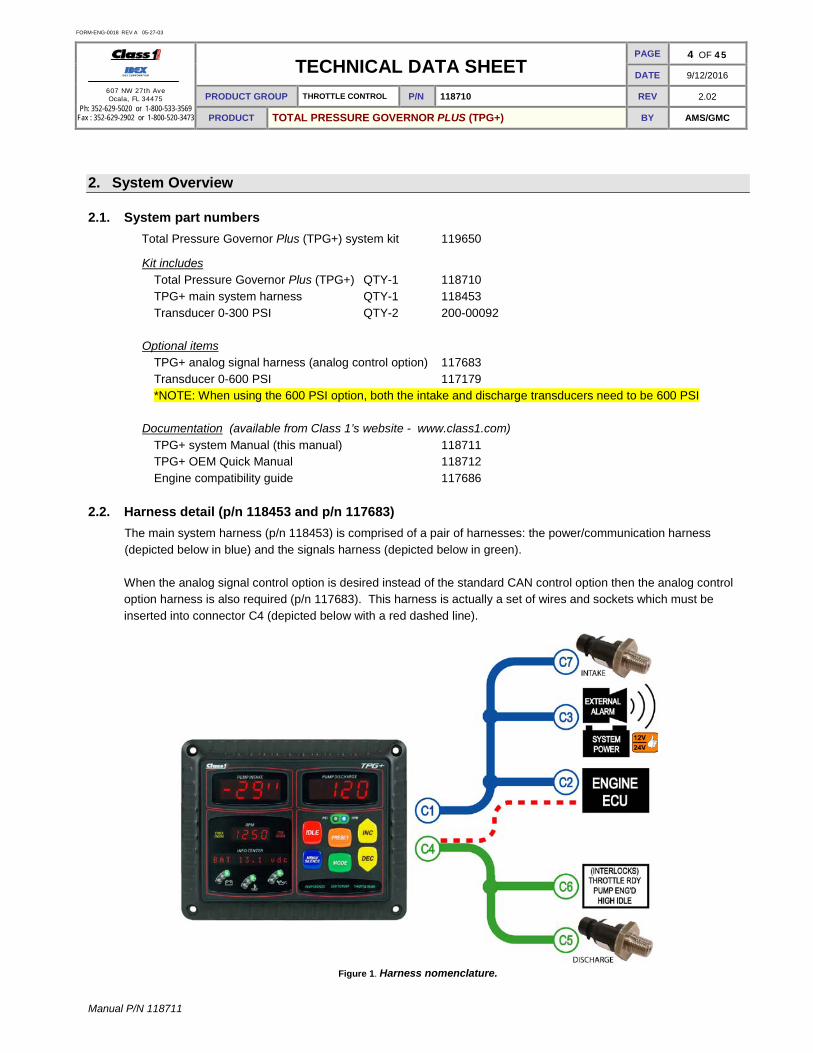
2.2. Harness detail (p/n 118453 and p/n 117683)
The main system harness (p/n 118453) is comprised of a pair of harnesses: the power/communication harness (depicted below in blue) and the signals harness (depicted below in green). When the analog signal control option is desired instead of the standard CAN control option then the analog control option harness is also required (p/n 117683). This harness is actually a set of wires and sockets which must be inserted into connector C4 (depicted below with a red dashed line).
Figure 1. Harness nomenclature.

FORM-ENG-0018 REV A 05-27-03
607 NW 27th Ave Ocala, FL 34475
Ph: 352-629-5020 or 1-800-533-3569 Fax : 352-629-2902 or 1-800-520-3473
TECHNICAL DATA SHEET PAGE 5 OF 45
DATE 9/12/2016
PRODUCT GROUP THROTTLE CONTROL P/N 118710 REV 2.02
PRODUCT TOTAL PRESSURE GOVERNOR PLUS (TPG+) BY AMS/GMC
Manual P/N 118711
Figure 2. Harness wiring detail - p/n 118453 with analog option harness p/n 117683 (red).

FORM-ENG-0018 REV A 05-27-03
607 NW 27th Ave Ocala, FL 34475
Ph: 352-629-5020 or 1-800-533-3569 Fax : 352-629-2902 or 1-800-520-3473
TECHNICAL DATA SHEET PAGE 6 OF 45
DATE 9/12/2016
PRODUCT GROUP THROTTLE CONTROL P/N 118710 REV 2.02
PRODUCT TOTAL PRESSURE GOVERNOR PLUS (TPG+) BY AMS/GMC
Manual P/N 118711
3. Overview of the Total Pressure Governor Plus
The Total Pressure Governor Plus (TPG+) p/n 118710 is an SAE J1939 Controller Area Network (CAN) device that controls engine speed using data communications directly to the engine ECU or through with an analog control signal. By operating on the J1939 network, the governor is able to monitor engine RPM and other pertinent data directly from the engine ECU. Engine information is available directly so that NFPA required instrumentation is delivered through a single unit saving panel space and delivering engine specific warnings as determined by each engine manufacturer.
Control algorithms are optimized to take advantage of the J1939 CAN data to yield crisp and accurate control of engine and subsequently pump speed and pressure output.
On units with starting with software version 7.xx the Governor when first installed and powered will step through an CAN Auto BUAD rate detection sequence. Once the Governor determines which BAUD rate the CAN bus is running on it will save it to memory.
For engines that may not support the data link control, an analog output signal is available to provide precise control of the engine speed and pressure.
The TPG+ saves pump panel space by incorporating easy to read numeric displays for Pump Intake pressure, Pump Discharge pressure, and engine RPM in accordance with NFPA standards.
Figure 3. TPG+ controls and indicators.

FORM-ENG-0018 REV A 05-27-03
607 NW 27th Ave Ocala, FL 34475
Ph: 352-629-5020 or 1-800-533-3569 Fax : 352-629-2902 or 1-800-520-3473
TECHNICAL DATA SHEET PAGE 7 OF 45
DATE 9/12/2016
PRODUCT GROUP THROTTLE CONTROL P/N 118710 REV 2.02
PRODUCT TOTAL PRESSURE GOVERNOR PLUS (TPG+) BY AMS/GMC
Manual P/N 118711
Pump intake pressure display section 3.9 Pump discharge pressure display section 3.10 Stop engine indicator section 3.11 Mode indicator section 3.4 Engine RPM display section 3.5 Switch panel section 3.3 Check engine indicator section 3.11 Idle section 3.3.1 Info Center display section 3.1 Menu/Silence section 3.3.2 Battery voltage monitor section 3.6 Preset section 3.3.3 Coolant temperature monitor section 3.7 Mode section 3.3.4 Oil pressure monitor section 3.8 Inc section 3.3.5 Dec section 3.3.6 Interlock status indicators section 3.2

FORM-ENG-0018 REV A 05-27-03
607 NW 27th Ave Ocala, FL 34475
Ph: 352-629-5020 or 1-800-533-3569 Fax : 352-629-2902 or 1-800-520-3473
TECHNICAL DATA SHEET PAGE 8 OF 45
DATE 9/12/2016
PRODUCT GROUP THROTTLE CONTROL P/N 118710 REV 2.02
PRODUCT TOTAL PRESSURE GOVERNOR PLUS (TPG+) BY AMS/GMC
Manual P/N 118711
3.1. Info Center display
The display shows status, warning, and information messages.
3.2. Interlock status indicators Backlit text indicates the status of the three (3) interlocks: pump engaged, okay to pump, and throttle ready. Throttle ready and pump engaged are physical inputs into the gray 12-pin connector (pins 2 and 10 respectively) Okay to pump interlock status can be configured to become active when both the throttle ready and pump engaged interlocks are present (default) or when the TPG+’s pin 4 physical input is active (see section 5.2.38).
3.3. Switch panel The six (6) control switches are color coded and labeled for easy identification.
3.3.1. IDLE
The IDLE switch (red) forces the governor to idle mode (standby). Pressing and holding this button for one second while in rpm or pressure mode will cause the engine to ramp down to its idle position.
3.3.2. MENU/SILENCE
The MENU/SILENCE switch (blue) is used to silence the alarm, cycle through the display items, and enter the setup menu.
3.3.3. PRESET
The PRESET switch (orange) sets the governor to the configured preset engine RPM while in throttle mode, or preset pressure while in pressure mode.
3.3.4. MODE
The MODE switch (green) sets the governor to either throttle mode (RPM) or pressure mode (PSI). The correct interlocks must be present for the system to begin governor operation: throttle ready for RPM mode, throttle ready, pump engaged, and okay to pump for PSI mode.
3.3.5. INC
The INC [increase] switch (yellow) is used to increase the engine RPM or pressure set point.
3.3.6. DEC
The DEC [decrease] switch (yellow) is used to decrease the engine RPM or pressure set point. 3.4. Mode indicator
The mode indicator consists of two (2) LEDs to show the governor’s current operating mode. The PSI LED (yellow) indicates the governor is operating in pressure mode and the RPM LED (blue) indicates the governor is operating in throttle mode. When both LEDs are OFF the governor is in idle mode (standby).
3.5. Engine RPM display
The engine RPM display shows the current engine RPM as reported by the Electronic Engine Controller 1 (EEC1) SAE J1939 network data message transmitted by the vehicle ECU.

FORM-ENG-0018 REV A 05-27-03
607 NW 27th Ave Ocala, FL 34475
Ph: 352-629-5020 or 1-800-533-3569 Fax : 352-629-2902 or 1-800-520-3473
TECHNICAL DATA SHEET PAGE 9 OF 45
DATE 9/12/2016
PRODUCT GROUP THROTTLE CONTROL P/N 118710 REV 2.02
PRODUCT TOTAL PRESSURE GOVERNOR PLUS (TPG+) BY AMS/GMC
Manual P/N 118711
3.6. Battery voltage monitor
The battery voltage monitor is comprised of three (3) LEDs (green, yellow, and red). The active LED color indicates the current system voltage’s range as measured by the power and ground inputs pins. The alarm will activate when the voltage monitor is in condition RED.
• GREEN 12.5VDC and higher • YELLOW 12.4VDC to 11.9VDC • RED 11.8VDC and lower
3.7. Coolant temperature monitor
The coolant temperature monitor is comprised of three (3) LEDs (green, yellow, and red). The active LED color indicates the status of the coolant temperature as reported by the Diagnostic Message 1 (DM1) SAE J1939 network data message transmitted by the vehicle ECU. The coolant temperature status can also be set to react to user desired points (see section 5.2.22). The alarm will activate when the coolant temperature monitor is in condition RED.
• GREEN No active error reported by engine for coolant temperature • YELLOW Coolant temperature high WARNING – SPN 110, FMI 16 • RED Coolant temperature high CRITICAL – SPN 110, FMI 0
3.8. Oil pressure monitor
The oil pressure monitor is comprised of three (3) LEDs (green, yellow, and red). The active LED color indicates the status of the oil pressure as reported by the Diagnostic Message 1 (DM1) SAE J1939 network data message transmitted by the vehicle ECU. The oil pressure status can also be set to react to user desired points (see section 5.2.22). The alarm will activate when the oil monitor is in condition RED.
• GREEN No active error reported by engine for oil pressure • YELLOW Oil pressure low WARNING – SPN 100, FMI 18 • RED Oil pressure low CRITICAL – SPN 100, FMI 1
3.9. Pump intake pressure display The pump intake pressure display shows the pressure as determined by the intake pressure sensor. By default, this display shows positive pressure in pounds per square inch (PSI) and negative pressure (vacuum) in inches of mercury (inHg), but it may be set up to display in metric units (see section 7.1).
3.10. Pump discharge pressure display The pump discharge pressure display shows the pressure as determined by the discharge pressure sensor. By default, this display only shows positive pressure in pounds per square inch (PSI), but it may be set up to display in metric units (see section 7.1).
3.11. Stop engine and check engine indicators The stop engine and check engine indicators are turned ON and OFF as directed by the Diagnostic Message 1 (DM1) SAE J1939 network data message transmitted by the vehicle ECU. These indicators are only able to function if the engine supports the Diagnostic Message 1 (DM1).

FORM-ENG-0018 REV A 05-27-03
607 NW 27th Ave Ocala, FL 34475
Ph: 352-629-5020 or 1-800-533-3569 Fax : 352-629-2902 or 1-800-520-3473
TECHNICAL DATA SHEET PAGE 10 OF 45
DATE 9/12/2016
PRODUCT GROUP THROTTLE CONTROL P/N 118710 REV 2.02
PRODUCT TOTAL PRESSURE GOVERNOR PLUS (TPG+) BY AMS/GMC
Manual P/N 118711
4. Operation 4.1. Initialization
The TPG+ has a six (6) second power initialization cycle and during this time the display will show:
First second after the power on cycle.
The TPG+ lights all indicators and shows “8.8.8.8. “ in the pump intake, pump discharge, and RPM display windows.
The Info Center shows “Class 1 TPG-X”. The last letter of this display indicates the configured control method of the TPG+.
TPG-C – CFPG control method TPG-P – PGN0 control method TPG-A – Analog control method TPG-P – PWM control method TPG-S – Scania control method TPG-V – Volvo control method TPG-M/N – MAN control method (section 6.2) TPG-F/G – FAW control method (section 6.2) TPG-D – Mercedes (Daimler) control method
(See section 7.4 for engine configuration).
Seconds 2 through 4 after the power on cycle.
The TPG+ continues to light all indicators and shows “8.8.8.8. “ in the pump intake, pump discharge, and RPM display windows.
The Info Center shows the software version of the TPG+.

FORM-ENG-0018 REV A 05-27-03
607 NW 27th Ave Ocala, FL 34475
Ph: 352-629-5020 or 1-800-533-3569 Fax : 352-629-2902 or 1-800-520-3473
TECHNICAL DATA SHEET PAGE 11 OF 45
DATE 9/12/2016
PRODUCT GROUP THROTTLE CONTROL P/N 118710 REV 2.02
PRODUCT TOTAL PRESSURE GOVERNOR PLUS (TPG+) BY AMS/GMC
Manual P/N 118711
The final two seconds after the power on cycle.
The TPG+ turns off all of the indicators and lights only the decimals of the pump intake, pump discharge, and RPM display windows.
The Info Center shows “Initializing”.
After the initialization the TPG+ begins normal operation.
4.2. Operating mode selection The TPG+ has two operating modes: throttle mode (RPM) and pressure mode (PSI).
Press the MODE switch to select an operating mode. An operating mode will only be activated if the required interlock(s) are in place (see section 4.3).
There is no variation in engine RPM or pump pressure when changing between throttle mode and pressure mode.
Pressure mode is the desired operating mode because it offers protection from pressure changes that could injure personnel.
4.2.1. Throttle mode
Throttle mode (RPM) maintains a set engine RPM and will not deviate until the operator changes the RPM with the control switches on the TPG+. (Proper interlocking is required for normal operation – refer to Required Interlocking section 4.3) Throttle mode is typically used when…
• priming the pump • connected to a stand pipe
• the water supply pressure stability is questionable • acting as a relay pumper
Press the MODE switch to select throttle mode. The display will momentarily show “GOV=THROTTLE” and the RPM mode indicator LED will illuminate blue.
Press the INC switch to increase or the DEC switch to decrease the engine RPM set point.
Press the PRESET switch to set the engine speed to the configured preset RPM - as long as the pump pressure is less than 10 PSI (see section 4.4). Configure the throttle mode preset through the Setup Menu (see section 5.2.1).
FORM-ENG-0018 REV A 05-27-03
607 NW 27th Ave Ocala, FL 34475
Ph: 352-629-5020 or 1-800-533-3569 Fax : 352-629-2902 or 1-800-520-3473
TECHNICAL DATA SHEET PAGE 12 OF 45
DATE 9/12/2016
PRODUCT GROUP THROTTLE CONTROL P/N 118710 REV 2.02
PRODUCT TOTAL PRESSURE GOVERNOR PLUS (TPG+) BY AMS/GMC
Manual P/N 118711
Press the IDLE switch at any time to set the TPG+ back to standby. The display will momentarily show “IDLE” and both mode indicator LEDs will be off (see section 4.5).
FORM-ENG-0018 REV A 05-27-03
607 NW 27th Ave Ocala, FL 34475
Ph: 352-629-5020 or 1-800-533-3569 Fax : 352-629-2902 or 1-800-520-3473
TECHNICAL DATA SHEET PAGE 13 OF 45
DATE 9/12/2016
PRODUCT GROUP THROTTLE CONTROL P/N 118710 REV 2.02
PRODUCT TOTAL PRESSURE GOVERNOR PLUS (TPG+) BY AMS/GMC
Manual P/N 118711
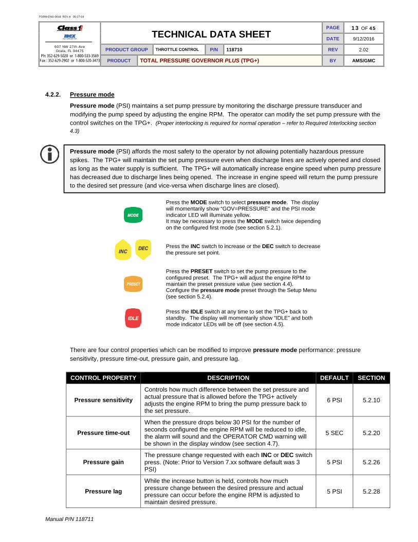
4.2.2. Pressure mode
Pressure mode (PSI) maintains a set pump pressure by monitoring the discharge pressure transducer and modifying the pump speed by adjusting the engine RPM. The operator can modify the set pump pressure with the control switches on the TPG+. (Proper interlocking is required for normal operation – refer to Required Interlocking section 4.3)
Pressure mode (PSI) affords the most safety to the operator by not allowing potentially hazardous pressure spikes. The TPG+ will maintain the set pump pressure even when discharge lines are actively opened and closed as long as the water supply is sufficient. The TPG+ will automatically increase engine speed when pump pressure has decreased due to discharge lines being opened. The increase in engine speed will return the pump pressure to the desired set pressure (and vice-versa when discharge lines are closed).
Press the MODE switch to select pressure mode. The display will momentarily show “GOV=PRESSURE” and the PSI mode indicator LED will illuminate yellow. It may be necessary to press the MODE switch twice depending on the configured first mode (see section 5.2.1).
Press the INC switch to increase or the DEC switch to decrease the pressure set point.
Press the PRESET switch to set the pump pressure to the configured preset. The TPG+ will adjust the engine RPM to maintain the preset pressure value (see section 4.4). Configure the pressure mode preset through the Setup Menu (see section 5.2.4).
Press the IDLE switch at any time to set the TPG+ back to standby. The display will momentarily show “IDLE” and both mode indicator LEDs will be off (see section 4.5).
There are four control properties which can be modified to improve pressure mode performance: pressure sensitivity, pressure time-out, pressure gain, and pressure lag.
CONTROL PROPERTY DESCRIPTION DEFAULT SECTION
Pressure sensitivity Controls how much difference between the set pressure and actual pressure that is allowed before the TPG+ actively adjusts the engine RPM to bring the pump pressure back to the set pressure.
6 PSI 5.2.10
Pressure time-out When the pressure drops below 30 PSI for the number of seconds configured the engine RPM will be reduced to idle, the alarm will sound and the OPERATOR CMD warning will be shown in the display window (see section 4.7).
5 SEC 5.2.20
Pressure gain The pressure change requested with each INC or DEC switch press. (Note: Prior to Version 7.xx software default was 3 PSI)
5 PSI 5.2.26
Pressure lag While the increase button is held, controls how much pressure change between the desired pressure and actual pressure can occur before the engine RPM is adjusted to maintain desired pressure.
5 PSI 5.2.28

FORM-ENG-0018 REV A 05-27-03
607 NW 27th Ave Ocala, FL 34475
Ph: 352-629-5020 or 1-800-533-3569 Fax : 352-629-2902 or 1-800-520-3473
TECHNICAL DATA SHEET PAGE 14 OF 45
DATE 9/12/2016
PRODUCT GROUP THROTTLE CONTROL P/N 118710 REV 2.02
PRODUCT TOTAL PRESSURE GOVERNOR PLUS (TPG+) BY AMS/GMC
Manual P/N 118711
4.3. Required interlocking The TPG+ requires interlocks before engine control operations are permitted. The TPG+ provides two interlock inputs that allow easy separation of pumping operations and throttle/high idle operations through two inputs dedicated as system interlocks: THROTTLE READY (pin 2 of the 12-pin Deutsch connector) and PUMP ENGAGED (pin 10 of the 12-pin Deutsch connector). A third interlock input (pin 4 of the 12-pin Deutsch connector (Hardware revision E) or pin 8 of the black 12-pin Deutsch connector (Hardware revision B and C)) may be configured to control OKAY TO PUMP (menu level 5, see section 5.2.38). These interlock inputs are activated when system power is applied (positive polarity). The OEM is responsible for creating safe and effective interlocking routines.
The TPG+ utilizes back lit text below the main display to indicate interlock status.
THROTTLE READY interlock PUMP ENGAGED interlock OKAY TO PUMP
Apply system power to pin 2 of the 12-pin Deutsch connector (through OEM interlocking). THROTTLE READY text illuminates green.
Apply system power to pin 10 of the 12-pin Deutsch connector (through OEM interlocking). PUMP ENGAGED text illuminates green.
When THROTTLE READY and PUMP ENGAGED interlocks are applied the OKAY TO PUMP text illuminates green (default), unless the OKAY TO PUMP interlock has been configured to function with pin 4, then the OKAY TO PUMP text only illuminates when pin 4 of the 12-pin Deutsch connector has system power applied (through OEM interlocking).
The TPG+ will operate in throttle mode (RPM) only.
The TPG+ will not operate in any mode until the THROTTLE READY interlock is applied.
The TPG+ will operate in throttle mode (RPM) or pressure mode (PSI).
4.4. PRESET switch operation
The PRESET switch brings the discharge pressure (or engine RPM, in throttle mode) to the configured preset point (see section 5.2.2 and 5.2.4).
Using the PRESET switch is a method of smoothly and expeditiously attaining water pressure and flow, but it is not intended to be the initial attack pressure. Attack pressures and flows should be determined by the actual fire status and manually achieved for best operation. PRESET is an operational convenience and needs to be considered as a fixed point (higher or lower than the current point) that can be achieved with a single switch press. Note: Initiating pumping operations is simplified by bringing the pump to a preset pressure with a single switch press. Consequently, securing or regaining control operations can be aided by returning to this fixed pressure point with a single switch press.

FORM-ENG-0018 REV A 05-27-03
607 NW 27th Ave Ocala, FL 34475
Ph: 352-629-5020 or 1-800-533-3569 Fax : 352-629-2902 or 1-800-520-3473
TECHNICAL DATA SHEET PAGE 15 OF 45
DATE 9/12/2016
PRODUCT GROUP THROTTLE CONTROL P/N 118710 REV 2.02
PRODUCT TOTAL PRESSURE GOVERNOR PLUS (TPG+) BY AMS/GMC
Manual P/N 118711
4.5. IDLE switch operation
Press and hold the IDLE switch for one second to release engine RPM control back to the engine ECU. The engine RPM will promptly go to its configured curb idle (see section 5.2.17).
Note: In view of the fact that driveline stress can be induced by quick changes in engine speed, depending on rpm and torque load, the engine speed is ramped to idle over a short duration to minimize the effect of driveline kick.
4.6. MENU/SILENCE switch operation
The MENU/SILENCE switch allows viewing (within the info center display) of the status of engine and pump related items (section 4.6.1) and silencing of an active alarm (section 4.6.2).
4.6.1. Viewing the engine and pump related items
Press the MENU/SILENCE switch to cycle through the engine and pump related display items (see below).
DISPLAY ITEM FORMAT SOURCE
Battery voltage BAT XX.X Vdc Input voltage at pins 1(+) and 12 (-) of the black 12-pin connector.
Engine oil pressure OIL XX PSI SAE J1939 CAN message – PGN 65263
Engine coolant temperature COOLANT XXX°F SAE J1939 CAN message – PGN 65262
Engine oil temperature OIL TMP XXX°F SAE J1939 CAN message – PGN 65262
Transmission oil temperature TRANS XXX°F SAE J1939 CAN message – PGN 65272
Engine fuel rate FUEL X.X G/h SAE J1939 CAN message – PGN 65266
Engine hours ENGINE XXXXh SAE J1939 CAN message – PGN 65253
Pump hours PUMP XX.Xh Internal timer based on pump engaged interlock
TPG+ alarm status ALARM XXX Alarm status Battery voltage
The info center displays the battery voltage as determined by the TPG+ based upon the voltage applied to pins 1 (+) and 12 (-) of the black 12-pin connector. Engine oil pressure
The info center displays the engine oil pressure based upon the J1939 CAN message received by the TPG+. The pressure will be displayed in PSI, kPa, or Bar dependent on the unit of measure configured in the setup menu (see section 5.2.1). Engine coolant temperature The info center displays the engine coolant temperature based upon the J1939 CAN message received by the TPG+. The temperature will be displayed in degrees Fahrenheit (°F) or degrees Celsius (°C) dependent on the unit of measure configured in the setup menu (see section 5.2.1). Engine oil temperature

FORM-ENG-0018 REV A 05-27-03
607 NW 27th Ave Ocala, FL 34475
Ph: 352-629-5020 or 1-800-533-3569 Fax : 352-629-2902 or 1-800-520-3473
TECHNICAL DATA SHEET PAGE 16 OF 45
DATE 9/12/2016
PRODUCT GROUP THROTTLE CONTROL P/N 118710 REV 2.02
PRODUCT TOTAL PRESSURE GOVERNOR PLUS (TPG+) BY AMS/GMC
Manual P/N 118711
The info center displays the engine oil temperature based upon the J1939 CAN message received by the TPG+. The temperature will be displayed in degrees Fahrenheit (°F) or degrees Celsius (°C) dependent on the unit of measure configured in the setup menu (see section 5.2.1).

FORM-ENG-0018 REV A 05-27-03
607 NW 27th Ave Ocala, FL 34475
Ph: 352-629-5020 or 1-800-533-3569 Fax : 352-629-2902 or 1-800-520-3473
TECHNICAL DATA SHEET PAGE 17 OF 45
DATE 9/12/2016
PRODUCT GROUP THROTTLE CONTROL P/N 118710 REV 2.02
PRODUCT TOTAL PRESSURE GOVERNOR PLUS (TPG+) BY AMS/GMC
Manual P/N 118711
Transmission oil temperature The info center displays the transmission oil temperature based upon the J1939 CAN message received by the TPG+. The temperature will be displayed in degrees Fahrenheit (°F) or degrees Celsius (°C) dependent on the unit of measure configured in the setup menu (see section 5.2.1). Engine fuel rate
The info center displays the engine fuel rate based upon the J1939 CAN message received by the TPG+. The fuel rate will be displayed in gallons per hour (G/h) or liters per hour (L/h) dependent on the unit of measure configured in the setup menu (see section 5.2.1). Engine hours The info center displays the engine hours (total hours of operation) based upon the J1939 CAN message received by the TPG+. Pump hours The info center displays the pump hours based upon the amount of time the TPG+ has detected the pump engaged interlock has been active. The pump hours may be cleared or set to a predetermined number of hours in the setup menu (see section 5.2.31). TPG+ alarm status
The info center displays the current alarm status of the TPG+. • The display will show ALARM OFF when the alarm is not active. • The display will show ALARM ON when the alarm is active. • The display will show ALARM SIL=XX when the alarm is active but has been silenced by the user. The
XX will be a value indicating the number of minutes until the alarm will again be allowed to sound (silenced time remaining).
4.6.2. Silencing the alarm
The active alarm can be silenced by pressing and holding the MENU/SILENCE switch for one second. The info center display will show ALARM SIL=10 to indicate that the alarm has been silenced for the standard time of 10 minutes. Continue holding the MENU/SILENCE switch to increase the silenced time frame to 15 or 20 minutes.
Press and hold the MENU/SILENCE switch for one second to silence the alarm for the standard time (10 minutes). Continue holding the MENU/SILENCE switch to increase the alarm silence time (15 or 20 minutes).
• The alarm silenced time frame is reset to the standard 10 minutes once all alarm conditions have been
cleared.
• The alarm will remain silenced for the selected time frame even if another alarm condition becomes active.

FORM-ENG-0018 REV A 05-27-03
607 NW 27th Ave Ocala, FL 34475
Ph: 352-629-5020 or 1-800-533-3569 Fax : 352-629-2902 or 1-800-520-3473
TECHNICAL DATA SHEET PAGE 18 OF 45
DATE 9/12/2016
PRODUCT GROUP THROTTLE CONTROL P/N 118710 REV 2.02
PRODUCT TOTAL PRESSURE GOVERNOR PLUS (TPG+) BY AMS/GMC
Manual P/N 118711
4.7. Status and warning messages The table below details the status and warning messages of the TPG+.
• These codes will flash on the Info Center display while the error/warning is active. • Multiple errors/warnings may be sequenced on the display. • Press and hold the MENU/SILENCE switch for one second to silence the active alarm (see section 4.6.2).
MESSAGE DESCRIPTION TPG+ RESPONSE OPERATOR ACTION
INTAKE SENS
DISCHG SENS
Signal voltage from the discharge or intake pressure sensor is less than +0.30VDC or greater than +4.90VDC. (Note: Used prior to software version 7.xx)
TPG+ switches to THROTTLE mode operation.
Operator may continue to use TPG+ in THROTTLE mode. Operator should have the discharge and/or intake pressure sensor and associated wiring verified.
DIS TXDCR LO
Signal voltage from pressure sensor is less than +0.30VDC
(Note: Only available with software version 7.xx)
TPG+ switches to THROTTLE mode operation.
Operator may continue to use TPG+ in THROTTLE mode. Operator should have the discharge pressure sensor and associated wiring verified.
DIS TXDCR HI
Signal voltage from pressure sensor is greater than +4.90VDC
(Note: Only available with software version 7.xx)
TPG+ switches to THROTTLE mode operation.
Operator may continue to use TPG+ in THROTTLE mode. Operator should have the discharge pressure sensor and associated wiring verified.
INT TXDCR LO
Signal voltage from pressure sensor is less than +0.30VDC
(Note: Only available with software version 7.xx)
Operator may continue to use TPG+. Operator should have the intake pressure sensor and associated wiring verified.
INT TXDCR HI
Signal voltage from pressure sensor is greater than +4.90VDC
(Note: Only available with software version 7.xx)
Operator may continue to use TPG+. Operator should have the intake pressure sensor and associated wiring verified.
WATER SUPPLY Pump discharge pressure decreased as RPM was increased (while in pressure mode).
TPG+ reduces engine speed to 1100 RPM and attempts to increase discharge pressure by ramping engine RPM.
Operator should verify water supply or change to THROTTLE mode.
OPERATOR CMD Pump intake pressure loss. Discharge pressure dropped below 30 PSI.
TPG+ maintains engine speed at 1100 RPM for the configured pressure time-out (5.2.20).
Operator should verify water supply or change to THROTTLE mode.
LOW PRESSURE Pump discharge pressure was greater than 50 PSI, but has dropped below 30 PSI.
TPG+ switches to STANDBY mode and the engine RPM reduced to IDLE.
Operator should verify water supply.
∆ RPM LIMIT
Engine RPM increase to compensate for a drop in pressure was not able to recover to the pressure set point (while in pressure mode).
TPG+ maintains the limit RPM. Operator should check for pump pressure capability.
∆ PSI LIMIT
Pump discharge pressure increased 50 PSI over the pressure point detected when the operator set the desired engine RPM (while in throttle mode).
TPG+ maintains THROTTLE mode operation but limits the engine RPM to maintain no more than a 50 PSI differential over the pressure detected when the operator set the desired engine RPM.
No operator action required. Operator may continue to use TPG+ in THROTTLE mode.
NO COMM DATA Not receiving CAN communication data from engine ECU (while throttle interlock is
TPG+ switches to THROTTLE mode operation.
Operator may continue to use TPG+ in THROTTLE mode. Operator should have the CAN

FORM-ENG-0018 REV A 05-27-03
607 NW 27th Ave Ocala, FL 34475
Ph: 352-629-5020 or 1-800-533-3569 Fax : 352-629-2902 or 1-800-520-3473
TECHNICAL DATA SHEET PAGE 19 OF 45
DATE 9/12/2016
PRODUCT GROUP THROTTLE CONTROL P/N 118710 REV 2.02
PRODUCT TOTAL PRESSURE GOVERNOR PLUS (TPG+) BY AMS/GMC
Manual P/N 118711
MESSAGE DESCRIPTION TPG+ RESPONSE OPERATOR ACTION active). communication wiring verified.
OUTPUT FAIL (No longer displayed in version 1.41 and above)
Output signal voltage differs from expected analog output value.
TPG+ switches to STANDBY mode.
Operator should have the engine reference voltages (8.1) verified.
SELECT MODE? Increase or Decrease request when no active mode (PSI/RPM) selected.
TPG+ waits for operator mode selection.
Operator should engage proper interlocks and select desired operating mode.
SWITCH FAIL Switch panel reporting the INC or DEC button is active during a power on cycle.
TPG+ freezes operation at the initialization screen. No operation permitted.
Operator should have the INC and/or DEC switches verified.
POS ECU REF
ECU Positive Reference missing from engine ECU.
(Note: Only used in analog engine type and software version 7.08 and greater)
Analog output Voltage shuts off. Operator should have the engine reference voltages (8.1) verified.
NEG ECU REF
ECU Negative Reference missing from engine ECU.
(Note: Only used in analog engine type and software version 7.08 and greater)
Analog output Voltage shuts off. Operator should have the engine reference voltages (8.1) verified.
FORM-ENG-0018 REV A 05-27-03
607 NW 27th Ave Ocala, FL 34475
Ph: 352-629-5020 or 1-800-533-3569 Fax : 352-629-2902 or 1-800-520-3473
TECHNICAL DATA SHEET PAGE 20 OF 45
DATE 9/12/2016
PRODUCT GROUP THROTTLE CONTROL P/N 118710 REV 2.02
PRODUCT TOTAL PRESSURE GOVERNOR PLUS (TPG+) BY AMS/GMC
Manual P/N 118711
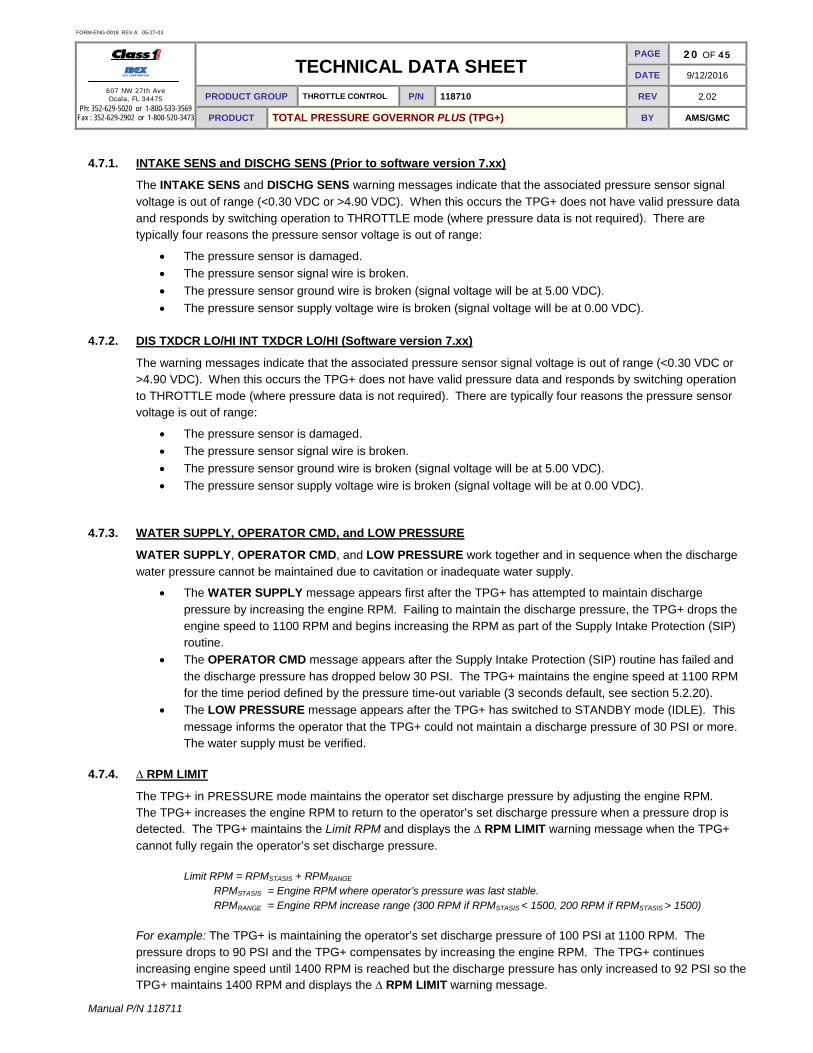
4.7.1. INTAKE SENS and DISCHG SENS (Prior to software version 7.xx)
The INTAKE SENS and DISCHG SENS warning messages indicate that the associated pressure sensor signal voltage is out of range (<0.30 VDC or >4.90 VDC). When this occurs the TPG+ does not have valid pressure data and responds by switching operation to THROTTLE mode (where pressure data is not required). There are typically four reasons the pressure sensor voltage is out of range:
• The pressure sensor is damaged. • The pressure sensor signal wire is broken. • The pressure sensor ground wire is broken (signal voltage will be at 5.00 VDC). • The pressure sensor supply voltage wire is broken (signal voltage will be at 0.00 VDC).
4.7.2. DIS TXDCR LO/HI INT TXDCR LO/HI (Software version 7.xx)
The warning messages indicate that the associated pressure sensor signal voltage is out of range (<0.30 VDC or >4.90 VDC). When this occurs the TPG+ does not have valid pressure data and responds by switching operation to THROTTLE mode (where pressure data is not required). There are typically four reasons the pressure sensor voltage is out of range:
• The pressure sensor is damaged. • The pressure sensor signal wire is broken. • The pressure sensor ground wire is broken (signal voltage will be at 5.00 VDC). • The pressure sensor supply voltage wire is broken (signal voltage will be at 0.00 VDC).
4.7.3. WATER SUPPLY, OPERATOR CMD, and LOW PRESSURE
WATER SUPPLY, OPERATOR CMD, and LOW PRESSURE work together and in sequence when the discharge water pressure cannot be maintained due to cavitation or inadequate water supply.
• The WATER SUPPLY message appears first after the TPG+ has attempted to maintain discharge pressure by increasing the engine RPM. Failing to maintain the discharge pressure, the TPG+ drops the engine speed to 1100 RPM and begins increasing the RPM as part of the Supply Intake Protection (SIP) routine.
• The OPERATOR CMD message appears after the Supply Intake Protection (SIP) routine has failed and the discharge pressure has dropped below 30 PSI. The TPG+ maintains the engine speed at 1100 RPM for the time period defined by the pressure time-out variable (3 seconds default, see section 5.2.20).
• The LOW PRESSURE message appears after the TPG+ has switched to STANDBY mode (IDLE). This message informs the operator that the TPG+ could not maintain a discharge pressure of 30 PSI or more. The water supply must be verified.
4.7.4. ∆ RPM LIMIT
The TPG+ in PRESSURE mode maintains the operator set discharge pressure by adjusting the engine RPM. The TPG+ increases the engine RPM to return to the operator’s set discharge pressure when a pressure drop is detected. The TPG+ maintains the Limit RPM and displays the ∆ RPM LIMIT warning message when the TPG+ cannot fully regain the operator’s set discharge pressure.
Limit RPM = RPMSTASIS + RPMRANGE
RPMSTASIS = Engine RPM where operator’s pressure was last stable. RPMRANGE = Engine RPM increase range (300 RPM if RPMSTASIS < 1500, 200 RPM if RPMSTASIS > 1500)
For example: The TPG+ is maintaining the operator’s set discharge pressure of 100 PSI at 1100 RPM. The pressure drops to 90 PSI and the TPG+ compensates by increasing the engine RPM. The TPG+ continues increasing engine speed until 1400 RPM is reached but the discharge pressure has only increased to 92 PSI so the TPG+ maintains 1400 RPM and displays the ∆ RPM LIMIT warning message.

FORM-ENG-0018 REV A 05-27-03
607 NW 27th Ave Ocala, FL 34475
Ph: 352-629-5020 or 1-800-533-3569 Fax : 352-629-2902 or 1-800-520-3473
TECHNICAL DATA SHEET PAGE 21 OF 45
DATE 9/12/2016
PRODUCT GROUP THROTTLE CONTROL P/N 118710 REV 2.02
PRODUCT TOTAL PRESSURE GOVERNOR PLUS (TPG+) BY AMS/GMC
Manual P/N 118711
4.7.5. ∆ PSI LIMIT
The TPG+ in THROTTLE mode maintains the operator set engine RPM. But the TPG+ will limit the discharge pressure if the pressure recorded at the last INC (or DEC) switch press has increased more than 50 PSI. The TPG+ will reduce the engine RPM to maintain the pressure increase to no more than a 50 PSI differential and display the ∆ PSI LIMIT warning message. The TPG+ does not attempt to regulate pressure while in THROTTLE mode, but it will attempt to limit a pressure increase to a maximum of 50 PSI over the pressure detected when the operator set the desired engine RPM.
For example: The TPG+ is maintaining the operator’s desired engine speed of 1100 RPM (at a discharge pressure of 100 PSI). The discharge pressure increases to 160 PSI (e.g. a discharge line was closed) and the TPG+ decreases the engine RPM until the discharge pressure is reduced to 150 PSI (50 PSI differential).
4.7.6. NO COMM DATA
The TPG+ receives engine RPM data via CAN communication (PGN 61444, SPN 190). The TPG+ displays the NO COMM DATA warning message after not receiving the RPM data for 4 or more seconds. The TPG+ will switch to THROTTLE mode (if originally in PRESSURE mode) and allow normal throttle mode control.
Note: If the TPG+ is configured for a CAN control and the NO COMM DATA message is active due to a CAN bus problem, then the control of the engine RPM cannot be certain since the engine ECU may not receive engine speed request data from the TPG+.
4.7.7. OUTPUT FAIL
A TPG+ configured for analog control will show the OUTPUT FAIL warning message if its analog engine control voltage signal is determined to not be the appropriately configured voltage. The TPG+ outputs a variable engine control voltage between 0.5 VDC and 4.5 VDC.
The following issues may cause the analog engine control voltage signal to be incorrect:
• The analog signal positive reference line is broken or missing (pin 1, 12-pin gray connector). • The analog signal ground reference line is broken or missing (pin 9, 12-pin gray connector). • The analog signal output line is externally shorted to ground or voltage (pin 8, 12-pin gray connector). • The TPG+ has an internal problem.
4.7.8. POS/NEG ECU REF (Software version 7.08 or greater)
A TPG+ configured for analog control will show the warning message if its analog engine control voltage signal is determined to not be the appropriately configured voltage. The TPG+ outputs a variable engine control voltage between 0.5 VDC and 4.5 VDC.
The following issues may cause the analog engine control voltage signal to be incorrect:
• The analog signal positive reference line is broken or missing (pin 1, 12-pin gray connector). • The analog signal ground reference line is broken or missing (pin 9, 12-pin gray connector). • The analog signal output line is externally shorted to ground or voltage (pin 8, 12-pin gray connector). • The TPG+ has an internal problem.
4.7.9. SELECT MODE?
The TPG+ will display the SELECT MODE? warning message when an operator presses the INC or DEC switches when an operating mode (THROTTLE or PRESSURE) has not been previously selected. The operator should first select an operating mode and then use the INC/DEC switches.

FORM-ENG-0018 REV A 05-27-03
607 NW 27th Ave Ocala, FL 34475
Ph: 352-629-5020 or 1-800-533-3569 Fax : 352-629-2902 or 1-800-520-3473
TECHNICAL DATA SHEET PAGE 22 OF 45
DATE 9/12/2016
PRODUCT GROUP THROTTLE CONTROL P/N 118710 REV 2.02
PRODUCT TOTAL PRESSURE GOVERNOR PLUS (TPG+) BY AMS/GMC
Manual P/N 118711
4.7.10. SWITCH FAIL
The TPG+ will display the SWITCH FAIL warning message if the INC and/or DEC switch is active during the power on cycle. The TPG+ will continue to show this message and not allow any operation until the affected switch is released.

FORM-ENG-0018 REV A 05-27-03
607 NW 27th Ave Ocala, FL 34475
Ph: 352-629-5020 or 1-800-533-3569 Fax : 352-629-2902 or 1-800-520-3473
TECHNICAL DATA SHEET PAGE 23 OF 45
DATE 9/12/2016
PRODUCT GROUP THROTTLE CONTROL P/N 118710 REV 2.02
PRODUCT TOTAL PRESSURE GOVERNOR PLUS (TPG+) BY AMS/GMC
Manual P/N 118711
4.8. Automatic display brightness The indicators and displays on the TPG+ can be user configured for brightness in both a DAY mode and a NIGHT mode (see sections 5.2.5 and 5.2.6). The TPG+ utilizes a light sensor on its front panel to determine if it is operating in DAY or NIGHT mode. The sensitivity of the light sensor is not configurable.
• When the light sensor detects light the TPG+ is set to DAY mode. • When the light sensor detects a low light condition the TPG+ is set to NIGHT mode.
The transition from DAY to NIGHT (or vice-versa) takes thirty (30) seconds. Note: The TPG+ will remain in NIGHT mode if the light sensor is blocked by stickers, tape, etc.
Figure 4. TPG+ light sensor location.

FORM-ENG-0018 REV A 05-27-03
607 NW 27th Ave Ocala, FL 34475
Ph: 352-629-5020 or 1-800-533-3569 Fax : 352-629-2902 or 1-800-520-3473
TECHNICAL DATA SHEET PAGE 24 OF 45
DATE 9/12/2016
PRODUCT GROUP THROTTLE CONTROL P/N 118710 REV 2.02
PRODUCT TOTAL PRESSURE GOVERNOR PLUS (TPG+) BY AMS/GMC
Manual P/N 118711
5. Governor Control Setup Menu 5.1. Engine compatibility
The factory default settings of the TPG+ make it “out of the box” ready to operate a Cummins engine programmed with the Emergency Vehicle Calibration. Typically, for the default configuration no values will require modification, other than changing the desired engine rpm, high-idle rpm and pump pressure preset values.
The governor is capable of controlling any engine that allows J1939 PGN0 (Torque Speed Control) messages from a unique source address. These engines include various Detroit Diesel DDEC engines, Mercedes Benz (MBE) engines, Volvo, and others. Programming of the source address or other parameters on the engine ECM may be required. The Scania engine allows control by proprietary J1939 messages and is supported by the TPG+. In cases where an engine does not support data link control, the TPG+ can be configured to control the engine with an analog signal coupled to the engine remote PTO throttle input. Contact Class 1 or visit our website (www.class1.com) for a complete engine compatibility list.
5.2. Enter the setup menu
The setup menu allows access to the configuration and calibration screens. The setup menu may be accessed anytime the TPG+ is in idle mode (see section 3.3.1). There are 5 set up menus available: menu level 1 (basic setup menu), menu level 2, menu level 3, menu level 4 (factory menu) and menu level 5 (restricted level). All configurations and calibrations are saved in non-volatile memory and will not be lost with power disruptions.
Standard menu level access
The standard menu level access method allows entry into menu levels 1, 2, or 3 only. Use the Direct menu level access method to enter menu level 4 or 5. Once a menu level has been selected, subsequent menu access will always enter that menu level and a system re-power is required to reset the first entry menu level.
+
Display shows MENU 04 SECS and begins counting down. Continue holding IDLE and MENU until the display shows *SETUP MENU* (4 seconds) and then release the switches. (If menu level 2 or menu level 3 is desired continue to hold the switches until the display shows the desired menu level then release).
Press the MENU switch to cycle through the available setup menu items.
or
Press the INC or DEC switches to modify the current menu item.
Press the PRESET switch to store the configured menu item. The display will show ---STORED---.
Press the MODE switch to exit the setup menu. The display will show --EXITMENU-- and then resume normal operation.
Direct menu level access
+
or
Enter a password while at idle to direct access a menu level. INC, DEC, DEC, INC, DEC, DEC, DEC, INC = menulevel 1 INC, DEC, DEC, INC, DEC, DEC, INC, DEC = menulevel 2 INC, DEC, DEC, INC, DEC, DEC, INC, INC = menulevel 3 INC, DEC, DEC, INC, DEC, INC, DEC, DEC = menulevel 4 INC, INC, DEC, INC, DEC, INC, DEC, INC = menulevel 5 (restricted)
FORM-ENG-0018 REV A 05-27-03
607 NW 27th Ave Ocala, FL 34475
Ph: 352-629-5020 or 1-800-533-3569 Fax : 352-629-2902 or 1-800-520-3473
TECHNICAL DATA SHEET PAGE 25 OF 45
DATE 9/12/2016
PRODUCT GROUP THROTTLE CONTROL P/N 118710 REV 2.02
PRODUCT TOTAL PRESSURE GOVERNOR PLUS (TPG+) BY AMS/GMC
Manual P/N 118711
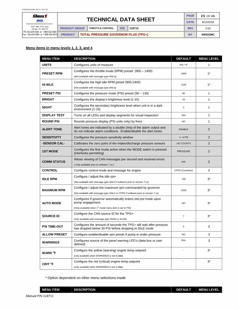
Menu items in menu levels 1, 2, 3, and 4
MENU ITEM DESCRIPTION DEFAULT MENU LEVEL
UNITS Configures units of measure PSI / ºF 1
PRESET RPM Configures the throttle mode (RPM) preset (900 – 1400) (Not available with message type ANLG)
1000 1*
HI-IDLE Configures the high idle RPM preset (900-1400)
(Not available with message type ANLG) 1100 1*
PRESET PSI Configures the pressure mode (PSI) preset (90 – 130) 90 1
BRIGHT Configures the display’s brightness level (1-15) 15 1
NIGHT Configures the secondary brightness level when unit is in a dark environment (1-15) 3 1
DISPLAY TEST Turns on all LEDs and display segments for visual inspection N/A 1
ROUND PSI Rounds pressure display (PSI units only) by fives NO 1
ALERT TONE Alert tones are indicated by a double chirp of the alarm output and do not indicate alarm conditions. Enable/disable the alert tones. ENABLE 2
SENSITIVITY Configures the pressure sensitivity window +/- 6 PSI 2
-SENSOR CAL- Calibrates the zero point of the intake/discharge pressure sensors 142 COUNTS 2
1ST MODE Configures the first mode active when the MODE switch is pressed (interlocks permitting) PRESSURE 2
COMM STATUS Allows viewing of CAN messages per second and received errors ( Only available prior to software 7.xx.)
N/A 2
CONTROL Configure control mode and message for engine CFPG (Cummins) 3
IDLE RPM Configure / adjust the idle rpm
(Not available with message type ANLG if software prior to version 7.xx) 700 3*
MAXIMUM RPM Configure / adjust the maximum rpm commanded by governor
(Not available with message type ANLG or CFPG if software prior to version 7.xx) 2200 3*
AUTO MODE Configures if governor automatically enters into psi mode upon pump engagement.
(Only available when 1st mode menu item is set to PSI) NO 3*
SOURCE ID Configure the CAN source ID for the TPG+ (only available with message type PGN0 or SCAN)
7 3*
PSI TIME-OUT Configures the amount of seconds the TPG+ will wait after pressure has dropped below 30 PSI before dropping to IDLE mode 5 3
ALLOW PRESET Configure enable/disable rpm preset if pump is under pressure NO 3
WARNINGS Configures source of the panel warning LED’s (data bus or user defined)
Bus 3
WARN °F Configure the yellow (warning) engine temp setpoint (only available when WARNINGS is set to Usr)
- 3*
CRIT °F Configure the red (critical) engine temp setpoint
(only available when WARNINGS is set to Usr)
- 3*
* Option dependent on other menu selections made
MENU ITEM DESCRIPTION DEFAULT MENU LEVEL

FORM-ENG-0018 REV A 05-27-03
607 NW 27th Ave Ocala, FL 34475
Ph: 352-629-5020 or 1-800-533-3569 Fax : 352-629-2902 or 1-800-520-3473
TECHNICAL DATA SHEET PAGE 26 OF 45
DATE 9/12/2016
PRODUCT GROUP THROTTLE CONTROL P/N 118710 REV 2.02
PRODUCT TOTAL PRESSURE GOVERNOR PLUS (TPG+) BY AMS/GMC
Manual P/N 118711
MENU ITEM DESCRIPTION DEFAULT MENU LEVEL
WARN PSI Configure the yellow (warning) oil pressure setpoint (only available when WARNINGS is set to Usr)
- 3*
CRIT PSI Configure the red (critical) oil pressure setpoint
(only available when WARNINGS is set to Usr) - 3*
XDCR Configures transducer type (300 or 600 psi) 300 3
CanBAUD Allows CAN BAUD rate selection 125, 250, and 500
( Only available on software 7.xx or greater.) 250 3
FACTORY DFLT Returns all menu parameters to the factory default state (Cummins Control – message type CFPG) 3
POC ASSERT Configures when idle offset is asserted (with power on cycle or mode switch) (Only available with message type ANLG)
NO 4*
GOV GAIN Configures the RPM change requested per INC or DEC switch press
(Only available with message type ANLG) 15 4*
PRESS GAIN Configures the pressure change requested per INC or DEC switch press
(Was 3 PSI prior to software version 7.xx) 5 PSI 4
DITHER Configure the engine handshake
(Only available with message type PGN0) NO 4*
LAG (∆PSI) Controls the response of the pressure increase when the INC button is held while in pressure mode.
(Not available with message type ANLG) 5 PSI 4*
PUMP HOURS Sets pump-engaged hours counter to a specified value N/A 4
BCM1 VER Configures the Scania BCM version (Only available with message type SCAN)
1 4*
SCANIA MODE Configures the Scania engine control type: NORMAL or STIFF
(Only available with message type SCAN) NORMAL 4*
IDLE STEPS Configures the idle offset voltage for analog control mode
(Only available with message type ANLG) 32 4*
Menu items in menu level 5
MENU ITEM DESCRIPTION DEFAULT MENU LEVEL
OK2PUMP Configure the “okay to pump” interlock source NORM 5
SPN 3350 Configure the PGN0 control purpose
(only available with message type PGN0) P32 5*
SPN 696 Configure the Engine Requested Speed Control Condition (only available with message type PGN0)
3 5*
HIDLE MODE Configure the high idle mode 1 5
BUS INTLKS Configure the bus interlocks N 5
VOLTS Calibrate the battery voltage display (+0.0 to +0.5 volts) +0.0 volts 5
SMOOTHING Configure pressure averaging (smoothing – NO, LO, HI) (Was LO prior to software version 7.xx)
NO 5
FORM-ENG-0018 REV A 05-27-03
607 NW 27th Ave Ocala, FL 34475
Ph: 352-629-5020 or 1-800-533-3569 Fax : 352-629-2902 or 1-800-520-3473
TECHNICAL DATA SHEET PAGE 27 OF 45
DATE 9/12/2016
PRODUCT GROUP THROTTLE CONTROL P/N 118710 REV 2.02
PRODUCT TOTAL PRESSURE GOVERNOR PLUS (TPG+) BY AMS/GMC
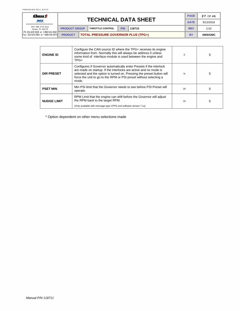
Manual P/N 118711
ENGINE ID Configure the CAN source ID where the TPG+ receives its engine information from. Normally this will always be address 0 unless some kind of interface module is used between the engine and TPG+
0 5
DIR PRESET
Configures if Governor automatically enter Presets if the interlock are made on startup. If the interlocks are active and no mode is selected and the option is turned on. Pressing the preset button will force the unit to go to the RPM or PSI preset without selecting a mode.
N 5
PSET MIN Min PSI limit that the Governor needs to see before PSI Preset will operate. 25 5
NUDGE LIMIT RPM Limit that the engine can drift before the Governor will adjust the RPM back to the target RPM.
(Only available with message type CFPG and software version 7.xx) 15 5
* Option dependent on other menu selections made
FORM-ENG-0018 REV A 05-27-03
607 NW 27th Ave Ocala, FL 34475
Ph: 352-629-5020 or 1-800-533-3569 Fax : 352-629-2902 or 1-800-520-3473
TECHNICAL DATA SHEET PAGE 28 OF 45
DATE 9/12/2016
PRODUCT GROUP THROTTLE CONTROL P/N 118710 REV 2.02
PRODUCT TOTAL PRESSURE GOVERNOR PLUS (TPG+) BY AMS/GMC
Manual P/N 118711
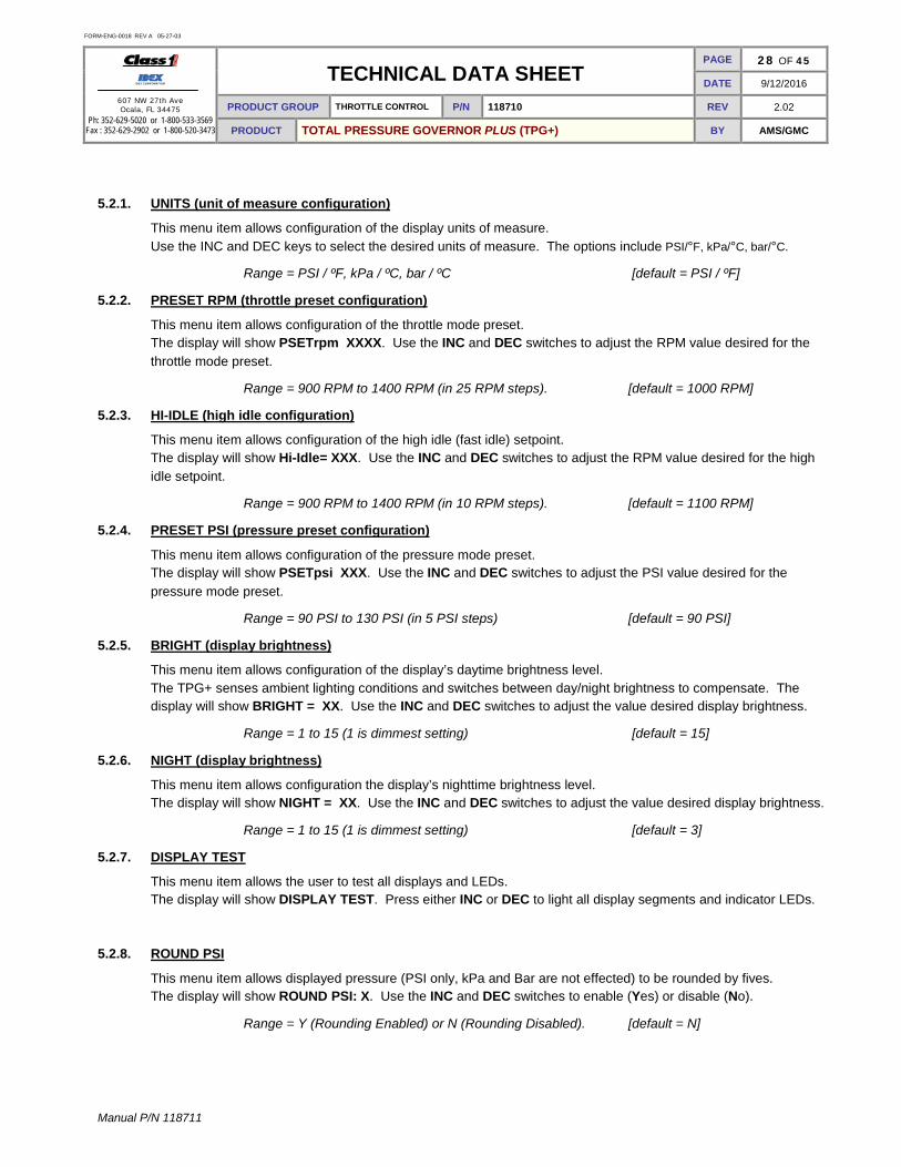
5.2.1. UNITS (unit of measure configuration)
This menu item allows configuration of the display units of measure. Use the INC and DEC keys to select the desired units of measure. The options include PSI/°F, kPa/°C, bar/°C.
Range = PSI / ºF, kPa / ºC, bar / ºC [default = PSI / ºF]
5.2.2. PRESET RPM (throttle preset configuration)
This menu item allows configuration of the throttle mode preset. The display will show PSETrpm XXXX. Use the INC and DEC switches to adjust the RPM value desired for the throttle mode preset.
Range = 900 RPM to 1400 RPM (in 25 RPM steps). [default = 1000 RPM]
5.2.3. HI-IDLE (high idle configuration)
This menu item allows configuration of the high idle (fast idle) setpoint. The display will show Hi-Idle= XXX. Use the INC and DEC switches to adjust the RPM value desired for the high idle setpoint.
Range = 900 RPM to 1400 RPM (in 10 RPM steps). [default = 1100 RPM]
5.2.4. PRESET PSI (pressure preset configuration)
This menu item allows configuration of the pressure mode preset. The display will show PSETpsi XXX. Use the INC and DEC switches to adjust the PSI value desired for the pressure mode preset.
Range = 90 PSI to 130 PSI (in 5 PSI steps) [default = 90 PSI]
5.2.5. BRIGHT (display brightness)
This menu item allows configuration of the display’s daytime brightness level. The TPG+ senses ambient lighting conditions and switches between day/night brightness to compensate. The display will show BRIGHT = XX. Use the INC and DEC switches to adjust the value desired display brightness.
Range = 1 to 15 (1 is dimmest setting) [default = 15]
5.2.6. NIGHT (display brightness)
This menu item allows configuration the display’s nighttime brightness level. The display will show NIGHT = XX. Use the INC and DEC switches to adjust the value desired display brightness.
Range = 1 to 15 (1 is dimmest setting) [default = 3]
5.2.7. DISPLAY TEST
This menu item allows the user to test all displays and LEDs. The display will show DISPLAY TEST. Press either INC or DEC to light all display segments and indicator LEDs.
5.2.8. ROUND PSI
This menu item allows displayed pressure (PSI only, kPa and Bar are not effected) to be rounded by fives. The display will show ROUND PSI: X. Use the INC and DEC switches to enable (Yes) or disable (No).
Range = Y (Rounding Enabled) or N (Rounding Disabled). [default = N]

FORM-ENG-0018 REV A 05-27-03
607 NW 27th Ave Ocala, FL 34475
Ph: 352-629-5020 or 1-800-533-3569 Fax : 352-629-2902 or 1-800-520-3473
TECHNICAL DATA SHEET PAGE 29 OF 45
DATE 9/12/2016
PRODUCT GROUP THROTTLE CONTROL P/N 118710 REV 2.02
PRODUCT TOTAL PRESSURE GOVERNOR PLUS (TPG+) BY AMS/GMC
Manual P/N 118711
5.2.9. ALERT TONE (configure alert tones)
This menu item allows enabling/disabling of the alert tones. The alert tones are sounded through the external alarm output (pin 10 of the black 12-pin connector). The display will show ALERT TONE:X. Use the INC and DEC switches to select Y (yes, enabled) or N (no, disabled).
Range = Y (Alert tones ON) or N (Alert tones OFF). [default = Y]
5.2.10. SENSITIVITY (pressure sensitivity configuration)
This menu item allows configuration of the pressure mode sensitivity window. This window dictates how much pressure difference must occur before the TPG+ adjusts the engine RPM to maintain the desired set pressure. The display will show GOV ± XX PSI. Use the INC and DEC switches to adjust the PSI value desired for the pressure mode sensitivity.
Range = ±4 PSI to ±12 PSI (in 1 PSI steps). [default = 6 PSI]
5.2.11. SENSOR CAL (pressure sensor calibration)
This menu item allows the zero point calibration of the intake and discharge pressure sensors. The display will show –SENSOR CAL-. See section 6.3 for the calibration procedure.
5.2.12. 1st MODE (first active mode configuration)
This menu item allows configuration of the governor mode active when the MODE switch is first pressed. The display will show 1st MODE=XXX. Use the INC and DEC switches to select the desired mode (PSI or RPM). Proper interlocks must be established for the configured 1st mode to become active during operation.
Range = RPM (throttle mode) or PSI (pressure mode). [default = PSI]
5.2.13. AUTO MODE (pressure mode automatically entered on pump engagement)
This menu item allows configuration of automatically entering pressure mode when pump engagement occurs (AUTO MODE?:Y). Note that this option will only be available if the 1st mode parameter (section 5.2.11) is set to pressure mode (PSI). When this parameter is enabled, the governor will be put in pressure mode when the pump is changed from a disengaged to an engaged position (interlocks permitting). Thereafter, when a user selects the IDLE (standby) mode, the governor will remain in standby mode until a new mode is selected.
Range = Y1 (Automode ON, Throttle Ready first then Pump Engaged), Y2 (Automode ON, Pump Engaged first then Throttle Ready), N (Automode OFF). [default = N]
5.2.14. COMM STATUS (view the CAN communication status)
This menu item allows viewing of the number of CAN messages per second and received errors (255 maximum). Errors are only logged when throttle ready interlock is active. The display will show COMM STATUS. Use the INC and DEC switches to toggle between message per second and received errors (NOTE: Only available prior to software version 7.xx).
FORM-ENG-0018 REV A 05-27-03
607 NW 27th Ave Ocala, FL 34475
Ph: 352-629-5020 or 1-800-533-3569 Fax : 352-629-2902 or 1-800-520-3473
TECHNICAL DATA SHEET PAGE 30 OF 45
DATE 9/12/2016
PRODUCT GROUP THROTTLE CONTROL P/N 118710 REV 2.02
PRODUCT TOTAL PRESSURE GOVERNOR PLUS (TPG+) BY AMS/GMC
Manual P/N 118711
5.2.15. CONTROL (engine control message type)
This menu item allows configuration of the CAN or ANALOG control message type. CFPG – Cummins Fire Pressure Governor, uses Cummins proprietary control message to control engine speed. MERC – Uses Mercedes control commands for PSM module equipped vehicles. PGN0 – Uses J1939, PGN0 – Torque Speed Control message to control engine speed. SCAN – SCANia, uses the Scania bodywork control message 1. ANLG – Uses analog voltage signal to control remote throttle input on engine. PWM – Uses pulse width modulation control signal (12-85%, 400 Hz). VLVO – Uses Volvo specific PTO control commands for Volvo FE/FL series engines running through a Volvo bodybuilder control module. This method should not be used when the TPG+ is directly connected to the engine CAN bus. Volvo FM/FH series engines should use the standard PGN0 control mode and set the Engine ID variable to the address of the body builder module. The display will show CONTROL=XXXX. Use the INC and DEC switches to adjust the control message type.
Range = CFPG, MERC, PGN0, SCAN, ANLG, PWM, VLVO [default = CFPG]
5.2.16. RPMidle (idle RPM value)
This menu item allows configuration of the idle RPM. The display will show RPMIdle=XXXX. Use the INC and DEC switches to adjust the RPM value desired for idle. Note: cannot be adjusted below the engine’s curb idle speed.
Range = 600 RPM to 1000 RPM (in 5 RPM steps). [default = 700 RPM]
5.2.17. RPMmaxi (maximum RPM value)
This menu item allows configuration of the maximum RPM that will be commanded when in PGN0 or SCANia mode. The display will show RPMmaxi=XXXX. Use the INC and DEC switches to adjust the maximum RPM value desired. This value cannot be adjusted above maximum governed speed.
Note: When control type is configured for Volvo (VLVO) or MAN the minimum value can be set down to 1500 RPM.
Range = 1900 RPM to 2500 RPM (in 25 RPM steps). [default = 2200 RPM]
Software Version 7.xx Range 1400 RPM to 2500 RPM [default = 2200 RPM]
5.2.18. SourceID (CAN message source identification)
This menu item allows configuration of the CAN source message ID number. The display will show SourceID=X. Use the INC and DEC switches to adjust the CAN source message ID.
Range = 0 – 255. [default = 7]
5.2.19. TSC1 RAMP (TSC1/PGN0 control mode RPM ramp speed)
This menu item allows configuration of the engine RPM ramp speed in TSC1/PGN0 control mode. The display will show TSC1 RAMP: X. Use the INC and DEC switches to adjust the ramp speed.
Range = 0 – 40. [default = 0]
5.2.20. DISPLAY (primary display in pressure mode)
This menu item allow configuration of the display data while operating in pressure mode. The display can show either engine speed (DISPLAY: RPM), or pump pressure (DISPLAY: PSI). The pump pressure will be displayed in the correct units of measure (psi, kPa, or bar) selected by the user. Note: The pressure display cannot be used as the master pressure gauge per NFPA 1901.
Range = RPM or PSI.

FORM-ENG-0018 REV A 05-27-03
607 NW 27th Ave Ocala, FL 34475
Ph: 352-629-5020 or 1-800-533-3569 Fax : 352-629-2902 or 1-800-520-3473
TECHNICAL DATA SHEET PAGE 31 OF 45
DATE 9/12/2016
PRODUCT GROUP THROTTLE CONTROL P/N 118710 REV 2.02
PRODUCT TOTAL PRESSURE GOVERNOR PLUS (TPG+) BY AMS/GMC
Manual P/N 118711
5.2.21. PSI TIME-OUT (pressure time out)
This menu item allows configuration of the low pressure time out. When the TPG+ is governing in pressure mode and the pressure falls below 30 PSI the TPG+ will wait the configured number of seconds to allow the pressure to rise before dropping to IDLE. The display will show PSI TIME-OUT. Use the INC and DEC switches to adjust the value desired for the pressure time out.
Range = 3 seconds to 10 seconds (in 1 second steps). [default = 5 seconds]
5.2.22. ALLOW PRESET (allow RPM preset use when pressure is detected)
This menu item allows enabling/disabling of throttle mode preset usage when pump pressure over 10 PSI is detected. The display will show PRESET RPM=X. Use the INC and DEC switches to select Y (yes, enabled) or N (no, disabled).
Range = Y (enabled) or N (disabled). [default = N]
5.2.23. WARNINGS (data monitor warning configuration)
This menu item allows configuration of the source for engine warnings. Warnings can be determined by engine diagnostic messages (DM1 messages) over the data bus (Bus), or at setpoints defined by the user based on J1939 oil pressure and engine temperature data (Usr). The preferred and most accurate method is to use Bus warnings from the engine diagnostic system. Note that not all engines support this feature, contact Class1 customer support for more information.
Range = Bus (bus controlled) or Usr (user configured). [default = Bus]
When the Usr configuration is selected the following setpoints will be assigned next. A. WARN ºF (USER DEFINED ENGINE TEMPERATURE HIGH WARNING - YELLOW LED)
B. CRIT ºF (USER DEFINED ENGINE TEMPERATURE HIGH CRITICAL - RED LED)
C. WARN PSI (USER DEFINED OIL PRESSURE LOW WARNING - YELLOW LED)
D. CRIT PSI (USER DEFINED OIL PRESSURE LOW CRITICAL - RED LED)
5.2.24. XDUCR (discharge pressure transducer range)
This menu item allows configuration the discharge pressure transducer’s range (0 to 300 PSI, or 0 to 600 PSI). The display will show XDCR= XXXPSI. Use the INC and DEC switches to adjust the value desired for the pressure change per button press.
Range = 300 PSI or 600 PSI. [default = 300 PSI]
5.2.25. FACTORY DFLT (Set factory defaults)
This menu item allows setting the TPG+ back to the factory defaults. The display will show FACTORY DFLT. Press the PRESET switch to load the defaults.
Refer to the menu level tables for the default values (section 5.2).

FORM-ENG-0018 REV A 05-27-03
607 NW 27th Ave Ocala, FL 34475
Ph: 352-629-5020 or 1-800-533-3569 Fax : 352-629-2902 or 1-800-520-3473
TECHNICAL DATA SHEET PAGE 32 OF 45
DATE 9/12/2016
PRODUCT GROUP THROTTLE CONTROL P/N 118710 REV 2.02
PRODUCT TOTAL PRESSURE GOVERNOR PLUS (TPG+) BY AMS/GMC
Manual P/N 118711
5.2.26. POC ASSERT (Power On Cycle assertion)
This menu item allows enabling/disabling of the analog control signal idle voltage assertion at power-up. When the POC ASSERT is enabled the analog control signal will be set to the configured idle voltage at the start of the TPG+’s power cycle. If the POC ASSERT is disabled the analog control signal will be set to the minimum configured level at the start of the TPG+’s power cycle. The display will show POC ASSERT:X. Use the INC and DEC switches to select Y or N.
Range = Y (enabled) or N (disabled). [default = N]
5.2.27. GOV GAIN (RPM change per step)
This menu item allows configuration of the RPM change per step. A larger number changes the RPM more with each INC or DEC switch press. The display will show GOV GAIN :XX. Use the INC and DEC switches to adjust the value.
Range = 0 to 35 [default = 15]
5.2.28. PRESS GAIN (PSI change per step)
This menu item allows configuration of the psi change per step. A larger number changes the PSI more with each INC or DEC switch press. The display will show X PSI/STEP. Use the INC and DEC switches to adjust the value.
Range = 1 to 5 [default = 3 PSI/STEP]
Software version 7.xx Range = 1 to 5 [default = 5 PSI/STEP]
5.2.29. DITHER (Engine handshake)
This menu item allows enabling/disabling of engine handshake. When enabled, the TPG+ will vary the engine speed +/- 5 RPM around the desired engine speed. Some engines may require consistent RPM modification in order to maintain remote RPM control. The display will show DITHER=XX. Use the INC and DEC switches to select ON or OFF.
Range = ON (enabled) or OFF (disabled). [default = OFF]
5.2.30. LAG ∆PSI (Pressure lag)
This menu item allows configuration of the pressure lag which defines the maximum allowable difference that the actual pressure is behind the commanded set-point before a “wait” (catch up) state is introduced while operating in pressure mode. The display will show LAG (∆PSI)=X. Use the INC and DEC switches to adjust the pressure lag value.
Range = 1 PSI to 20 PSI (in 1 PSI steps). [default = 5 PSI]
5.2.31. PUMP HOURS
This menu item allows setting/resetting of the total pump hours. The display will show PUMP X.Xh. Use the INC and DEC switches to adjust the pump hours.
Range = 0.0 to 999.9 hours (in 0.1 hour steps). [default = 0]
5.2.32. BCM1 VER (Body Control Message 1 version)
This menu item allows configuration of the message configuration version transmitted in the Scania Body Control Message 1. The display will show BCM1 VER: X. Use the INC and DEC switches to adjust the value.
Range = 0 to 255. [default = 1]

FORM-ENG-0018 REV A 05-27-03
607 NW 27th Ave Ocala, FL 34475
Ph: 352-629-5020 or 1-800-533-3569 Fax : 352-629-2902 or 1-800-520-3473
TECHNICAL DATA SHEET PAGE 33 OF 45
DATE 9/12/2016
PRODUCT GROUP THROTTLE CONTROL P/N 118710 REV 2.02
PRODUCT TOTAL PRESSURE GOVERNOR PLUS (TPG+) BY AMS/GMC
Manual P/N 118711
5.2.33. SCANIA MODE? (Scania governor type) (Prior to software version 7.xx)
This menu item allows configuration of the Scania requested governor type in the Body Control Message 1. The display will show MODE: XXXXXX. Use the INC and DEC switches to adjust the value.
Range = NORMAL or STIFF. [default = NORMAL]
5.2.34. SCANIA MODE? (Scania governor type) (Available software version 7.xx)
This menu item allows configuration of the Scania requested governor type. The display will show MODE: XXXXXX. Use the INC and DEC switches to adjust the value.
Range = SCANIA-1(BCM) or SCANIA-2 (BCI). [default = SCANIA-1]
5.2.35. SCANIA CONTROL TYPE? (Scania governor type) (Available software version 7.xx)
This menu item allows configuration of the Scania requested governor type Body Control Message 1. The display will show MODE: XXXXXX. Use the INC and DEC switches to adjust the value.
Range = NORMAL or STIFF. [default = NORMAL]
5.2.36. VOLVO CONTROL MODE? (Volvo governor type) (Available software version 7.xx)
This menu item allows configuration of the Volvo requested governor type. The display will show XX/XX. Use the INC and DEC switches to adjust the value.
Range = FE/FL or FH/FM. [default = FE/FL]
5.2.37. IDLE STEPS (Analog control idle)
This menu item allows the configuration of the analog control signal idle voltage. The display will show IdleSteps:XX. Use the INC and DEC switches to adjust the value.
Range = 0 to 60 [default = 32]
5.2.38. OKAY2PUMP (Okay to pump interlock source)
This menu item allows the configuration of the “okay to pump” interlock source. NORM – The OKAY TO PUMP text only illuminates when the throttle ready and pump engaged interlocks are
active. PIN4 – The OKAY TO PUMP text only illuminates when pin 4 of the 12-pin Deutsch connector has power
applied. The display will show OK2PUMP=X. Use the INC and DEC switches to adjust the value.
Range = NORM or PIN4 [default = NORM]
Note: Software version 7.xx if power is applied to the pin it will automatically configure and save to allow PKAY TO PUMP to work with PIN4.
5.2.39. SPN 3350 (TSC1 – SPN 3350)
This menu item allows configuration of the Torque Speed Control 1 (TSC1) control purpose message. P03 – PTO governor control purpose. P32 – Temporary power-train control purpose. The display will show SPN 3350:XXX . Use the INC and DEC switches to adjust the CAN purpose.
Range = P03 or P32. [default = P32]
FORM-ENG-0018 REV A 05-27-03
607 NW 27th Ave Ocala, FL 34475
Ph: 352-629-5020 or 1-800-533-3569 Fax : 352-629-2902 or 1-800-520-3473
TECHNICAL DATA SHEET PAGE 34 OF 45
DATE 9/12/2016
PRODUCT GROUP THROTTLE CONTROL P/N 118710 REV 2.02
PRODUCT TOTAL PRESSURE GOVERNOR PLUS (TPG+) BY AMS/GMC
Manual P/N 118711
5.2.40. SPN 696 (Engine Requested Speed Control Condition)
This menu item allows configuration of the CAN Engine Requested Speed Control Condition (SPN 696), as defined in SAE J1939 for the TSC1/PGN0 speed control command. Possible values are: 0 – Transient optimized for driveline disengaged and non-lockup conditions. 1 – Stability optimized for driveline disengaged and non-lockup conditions. 2 – Stability optimized for driveline engaged and/or and in lockup condition 1 (e.g. vehicle driveline). 3 – Stability optimized for driveline engaged and/or and in lockup condition 2 (e.g. PTO driveline). The display will show SPN 696:X. Use the INC and DEC switches to adjust the Engine Requested Speed Control Condition.
Range = 0 to 3. [default = 3]
5.2.41. TSC1 MODE? (Available software version 7.xx)
This menu item allows configuration of the TSC1 engine types. The display will show MODE: XXXXXX. Use the INC and DEC switches to adjust the value. NORMAL_Engine = standard TSC1, no transmit at IDLE or without throttle ready interlock. NORMAL_Engine_2 = standard TSC1, but transmits at idle without throttle ready interlock. FAW_Engine = special TSC1, transmits at idle without throttle ready interlock, always "speed control". FAW_Engine_2 = special TSC1, transmits at idle without throttle ready interlock, standard "override disabled" and "speed control". MAN_Engine = special TSC1, no transmit at IDLE or without throttle ready interlock. MAN_Engine_2 = special TSC1, but transmits at idle without throttle ready interlock.
[default = NORMAL] 5.2.42. HI IDLE MODE
This menu item allows configuration of the high idle mode. 1 – Normal. 2 – Only allow high idle if engine speed > 600 RPM, transmission is in neutral, and okay to pump interlock is OFF.
Forces the throttle ready interlock OFF when transmission is NOT in neutral or 4th gear. The display will show HIDLE MODE:X . Use the INC and DEC switches to adjust the value.
Range = 1 or 2. [default = 1]
5.2.43. BUS INTLKS (Bus message control of throttle ready interlock)
This menu item allows configuration of the bus interlocks. N – Normal, throttle ready interlock ON with its physical input pin. Y – Forces throttle ready interlock ON when transmission is in Neutral. The display will show BUS INTLKS:X . Use the INC and DEC switches to adjust the value.
Range = Y or N.
[default = N]
5.2.44. VOLTS (Voltage display calibration)
This menu item allows calibration of the voltage display. The display will show VOLTS XX.X V. Use the INC and DEC switches to adjust the voltage level.
Range = voltage + 0.0 to voltage + 0.5 [default = 0]
FORM-ENG-0018 REV A 05-27-03
607 NW 27th Ave Ocala, FL 34475
Ph: 352-629-5020 or 1-800-533-3569 Fax : 352-629-2902 or 1-800-520-3473
TECHNICAL DATA SHEET PAGE 35 OF 45
DATE 9/12/2016
PRODUCT GROUP THROTTLE CONTROL P/N 118710 REV 2.02
PRODUCT TOTAL PRESSURE GOVERNOR PLUS (TPG+) BY AMS/GMC
Manual P/N 118711
5.2.45. SMOOTHING (Pressure display averaging)
This menu item allows configuration of the smoothing (averaging) method of the pressure display. NO – No averaging of pressure. LO – Average of 4 pressure samples while within pressure stasis window. HI – Average of 8 pressure samples while within pressure stasis window. The display will show SMOOTHING:XX. Use the INC and DEC switches to adjust the value.
Range = NO, LO, or HI [default = LO]
Range = NO, LO, or HI Software version 7.xx [default = NO]
5.2.46. ENGINE ID (Source ID of received engine messages)
This menu item allows configuration of the CAN source ID for engine messages received by the TPG+. The display will show EngineID=X. Use the INC and DEC switches to adjust the CAN engine source ID. If the TPG+ continuously displays the NO COMM DATA message with the engine running and the CAN bus connected verify the setting of this parameter. Where the TPG+ is directly connected to the engine’s CAN bus the address should usually be 0 but if there is a gateway module between the engine and TPG+ then this parameter needs to be set to the address from which the gateway module transmits.
Range = 0 – 255. [default = 0]

FORM-ENG-0018 REV A 05-27-03
607 NW 27th Ave Ocala, FL 34475
Ph: 352-629-5020 or 1-800-533-3569 Fax : 352-629-2902 or 1-800-520-3473
TECHNICAL DATA SHEET PAGE 36 OF 45
DATE 9/12/2016
PRODUCT GROUP THROTTLE CONTROL P/N 118710 REV 2.02
PRODUCT TOTAL PRESSURE GOVERNOR PLUS (TPG+) BY AMS/GMC
Manual P/N 118711
6. Special Function Passwords (See section 5.2 for procedure on entering passwords) 6.1. Setting control message transmission requirements DEC, INC, INC, INC, DEC, DEC, DEC, DEC Engine control message is not transmitted when at idle (no mode selected) - displays message "NOTX AT IDLE" after password is entered. This can be useful if there is more than one device on a vehicle which is controlling the RPM externally over the CAN bus. DEC, INC, INC, INC, DEC, DEC, DEC, INC Engine control message is transmitted whenever the throttle interlock is active - displays message "TX AT IDLE" after password is entered. This was the standard operation for TPG+ version 3.2 and below and is the default on newer versions. 6.2. Setting control for specific engine types DEC, INC, DEC, INC, DEC, DEC, DEC, DEC NORMAL_Engine = standard TSC1, no transmit at IDLE or without throttle ready interlock. (Note: Only available prior to software version 7.xx. Has been moved to menu when selecting engine type) DEC, INC, DEC, INC, DEC, DEC, DEC, INC NORMAL_Engine_2 = standard TSC1, but transmits at idle without throttle ready interlock. (Note: Only available prior to software version 7.xx. Has been moved to menu when selecting engine type) DEC, INC, DEC, INC, DEC, DEC, INC, DEC FAW_Engine = special TSC1, transmits at idle without throttle ready interlock, always "speed control". (Note: Only available prior to software version 7.xx. Has been moved to menu when selecting engine type) DEC, INC, DEC, INC, DEC, DEC, INC, INC FAW_Engine_2 = special TSC1, transmits at idle without throttle ready interlock, standard "override disabled" and "speed control". (Note: Only available prior to software version 7.xx. Has been moved to menu when selecting engine type) DEC, INC, DEC, INC, DEC, INC, DEC, DEC MAN_Engine = special TSC1, no transmit at IDLE or without throttle ready interlock. (Note: Only available prior to software version 7.xx. Has been moved to menu when selecting engine type) DEC, INC, DEC, INC, DEC, INC, DEC, INC MAN_Engine_2 = special TSC1, but transmits at idle without throttle ready interlock. (Note: Only available prior to software version 7.xx. Has been moved to menu when selecting engine type) 6.3. Configuring transmission of Hydraulic Pressure Governor message DEC, INC, INC, DEC, DEC, DEC, DEC, DEC Transmit HPG message (default) - displays message "HPG = ON" after password is entered. DEC, INC, INC, DEC, DEC, DEC, DEC, INC Don't transmit HPG message - displays message "HPG = OFF" after password is entered. DEC, INC, INC, DEC, INC, DEC, DEC, DEC HPG message transmits mode normally - displays message "HPG MODE = NOR" after password is entered. DEC, INC, INC, DEC, INC, DEC, DEC, INC HPG message transmits PSI mode always - displays message "HPG MODE = PSI" after password is entered.

FORM-ENG-0018 REV A 05-27-03
607 NW 27th Ave Ocala, FL 34475
Ph: 352-629-5020 or 1-800-533-3569 Fax : 352-629-2902 or 1-800-520-3473
TECHNICAL DATA SHEET PAGE 37 OF 45
DATE 9/12/2016
PRODUCT GROUP THROTTLE CONTROL P/N 118710 REV 2.02
PRODUCT TOTAL PRESSURE GOVERNOR PLUS (TPG+) BY AMS/GMC
Manual P/N 118711
DEC, INC, INC, INC, DEC, INC, DEC, DEC Reset Factory Defaults (Only available software version 7.xx). DEC, INC, INC, INC, DEC, INC, INC, DEC Reset Auto BAUD Rate Detection (Only available software version 7.xx).

FORM-ENG-0018 REV A 05-27-03
607 NW 27th Ave Ocala, FL 34475
Ph: 352-629-5020 or 1-800-533-3569 Fax : 352-629-2902 or 1-800-520-3473
TECHNICAL DATA SHEET PAGE 38 OF 45
DATE 9/12/2016
PRODUCT GROUP THROTTLE CONTROL P/N 118710 REV 2.02
PRODUCT TOTAL PRESSURE GOVERNOR PLUS (TPG+) BY AMS/GMC
Manual P/N 118711
7. Configuration 7.1. Configure the unit of measure
The TPG+ can be configured for English (PSI, ºF) of Metric (kPa or bar, ºC) units of measure.
Follow the sequence below to set the unit of measure for the TPG+.
+
Display shows MENU 04 SECS and begins counting down. Continue holding IDLE and MENU until the display shows *SETUP MENU* (4 seconds).
ONCE The display shows the menu item: UNITS: XXX/ºX.
ONCE Press the INC switch to select the desired unit of measure: PSI/ºF, kPa/ºC, or bar/ ºC.
ONCE Press the PRESET switch once. The display shows ---STORED---. The unit of
measure has been saved.
ONCE Press the IDLE switch once. The display shows —EXITMENU— and then restarts
normal operation. 7.2. Select pressure transducer range: 300 PSI (default) or 600 PSI
Normally the default 300 PSI transducer is sufficient for most pump applications but if a higher pump pressure range is required the TPG+ can be programmed to use a 600 PSI transducer.
Follow the sequence below to select the desired pressure transducer range.
+
or
Enter menu level 3 by pressing and holding the IDLE switch while entering the following password. INC, DEC, DEC, INC, DEC, DEC, INC, INC
Toggle the MENU/SILENCE switch until the display shows XDCR= XXX.
(XXX = 300 or 600)
Press the INC switch to select the desired pressure transducer range (300 or 600).
ONCE Press the PRESET switch once. The display shows --- STORED---. The pressure
transducer range has been saved.
ONCE Press the IDLE switch once. The display shows —EXITMENU— and then restarts
normal operation.

FORM-ENG-0018 REV A 05-27-03
607 NW 27th Ave Ocala, FL 34475
Ph: 352-629-5020 or 1-800-533-3569 Fax : 352-629-2902 or 1-800-520-3473
TECHNICAL DATA SHEET PAGE 39 OF 45
DATE 9/12/2016
PRODUCT GROUP THROTTLE CONTROL P/N 118710 REV 2.02
PRODUCT TOTAL PRESSURE GOVERNOR PLUS (TPG+) BY AMS/GMC
Manual P/N 118711
7.3. Zero calibrate the intake and discharge pressure transducers
The pressures indicated by the TPG+ may not show ‘0’ when the pump intake or discharge pressures are actually zero due to ambient pressure and altitude at your locale.
Follow the sequence below to zero calibrate the intake and discharge pressure transducers.
+
Display shows MENU 04 SECS and begins counting down. Continue holding IDLE and MENU until the display shows *SETUP MENU* (4 seconds) and then MENU LEVEL 2 (2 seconds).
Toggle the MENU/SILENCE switch until display shows the menu item: -SENSOR CAL-
ONCE Press the INC switch once. The display shows SENSORS ZERO and the Intake and
Discharge displays show the current sensor zero values.
+ HOLD
Press the INC switch and hold. The display shows SENSORS LIVE and the Intake and Discharge displays show the live sensor values. Verify the values are between 130 and 155. Release the INC switch. The display will show SENSORS ZERO.
ONCE
Press the PRESET switch once. The display shows ZERO STORED and the Intake and Discharge displays show the new sensor zero values. Verify they are between 130 and 155.
ONCE Press the IDLE switch once. The display shows —EXITMENU— and then restarts
normal operation.
7.4. Configure the engine control method The TPG+ has 4 engine control methods to cover several engine types and configuration.
CFPG – Cummins Fire Pressure Governor, uses Cummins proprietary control message to control engine speed. PGN0 – Uses J1939, PGN0 – Torque Speed Control message to control engine speed. SCAN – SCANia, uses the Scania bodywork control message 1. ANLG – Uses analog voltage signal to control remote throttle input on engine.
VLVO – Uses Volvo specific PTO control commands for Volvo FE/FL series engines running through a bodybuilder module.
+
or
Enter menu level 3 by pressing and holding the IDLE switch while entering the following password. INC, DEC, DEC, INC, DEC, DEC, INC, INC
ONCE The display shows the menu item: CONTROL=XXXX (CFPG, PGN0, SCAN, or ANLG)
OR
Select the desired engine control method: CFPG, PGN0, SCAN, or ANLG
ONCE Press the PRESET switch once. The display shows ---STORED---. The engine control
method has been saved.
ONCE Press the IDLE switch once. The display shows —EXITMENU— and then restarts
normal operation.
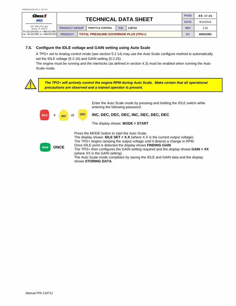
FORM-ENG-0018 REV A 05-27-03
607 NW 27th Ave Ocala, FL 34475
Ph: 352-629-5020 or 1-800-533-3569 Fax : 352-629-2902 or 1-800-520-3473
TECHNICAL DATA SHEET PAGE 40 OF 45
DATE 9/12/2016
PRODUCT GROUP THROTTLE CONTROL P/N 118710 REV 2.02
PRODUCT TOTAL PRESSURE GOVERNOR PLUS (TPG+) BY AMS/GMC
Manual P/N 118711
7.5. Configure the IDLE voltage and GAIN setting using Auto Scale A TPG+ set to Analog control mode (see section 5.2.14) may use the Auto Scale configure method to automatically set the IDLE voltage (5.2.16) and GAIN setting (5.2.25). The engine must be running and the interlocks (as defined in section 4.3) must be enabled when running the Auto Scale mode.
The TPG+ will actively control the engine RPM during Auto Scale. Make certain that all operational precautions are observed and a trained operator is present.
+
or
Enter the Auto Scale mode by pressing and holding the IDLE switch while entering the following password. INC, DEC, DEC, DEC, INC, DEC, DEC, DEC The display shows: MODE = START
ONCE
Press the MODE button to start the Auto Scale. The display shows: IDLE SET = X.X (where X.X is the current output voltage). The TPG+ begins ramping the output voltage until it detects a change in RPM. Once IDLE point is detected the display shows FINDING GAIN The TPG+ then configures the GAIN setting required and the display shows GAIN = XX (where XX is the GAIN setting). The Auto Scale mode completes by saving the IDLE and GAIN data and the display shows STORING DATA.

FORM-ENG-0018 REV A 05-27-03
607 NW 27th Ave Ocala, FL 34475
Ph: 352-629-5020 or 1-800-533-3569 Fax : 352-629-2902 or 1-800-520-3473
TECHNICAL DATA SHEET PAGE 41 OF 45
DATE 9/12/2016
PRODUCT GROUP THROTTLE CONTROL P/N 118710 REV 2.02
PRODUCT TOTAL PRESSURE GOVERNOR PLUS (TPG+) BY AMS/GMC
Manual P/N 118711
8. Mounting & installation 8.1. Panel cutout dimensions
Figure 5. Installation dimensions in inches [millimeters].

FORM-ENG-0018 REV A 05-27-03
607 NW 27th Ave Ocala, FL 34475
Ph: 352-629-5020 or 1-800-533-3569 Fax : 352-629-2902 or 1-800-520-3473
TECHNICAL DATA SHEET PAGE 42 OF 45
DATE 9/12/2016
PRODUCT GROUP THROTTLE CONTROL P/N 118710 REV 2.02
PRODUCT TOTAL PRESSURE GOVERNOR PLUS (TPG+) BY AMS/GMC
Manual P/N 118711
9. Connector Description
9.1. TPG+ connectors (Hardware revision A)
The module has two connectors and the following definitions apply:
Mating connector: Deutsch DT06-12SB BLACK Mating sockets: Deutsch 0462-201-16141 Gold mating sockets: Deutsch 0462-201-1631 Wedge lock: W12S Recommended wire gage: 16-20 AWG PIN CIRCUIT DESCRIPTION 1 SUPPLY (+) (INPUT) – battery voltage (+9VDC…+32VDC) 2 CAN HIGH (DATA) – SAE J1939 CAN 2.0B, 125-500Kbits/s * 3 CAN SHIELD (DATA) – SAE J1939 CAN 2.0B, 125-500Kbits/s * 4 ---- ---- 5 Sensor GND (OUTPUT) – Intake pressure ground 6 Sensor REF (OUTPUT) – Intake pressure supply (+5VDC) 7 Sensor SIGNAL (INPUT) – Intake pressure signal (+0.5VDC to +4.5VDC) 8 ---- ---- 9 ---- ----
10 ALARM (-) (OUTPUT) – alarm active (ground polarity, 250mA) 11 CAN LOW (DATA) – SAE J1939 CAN 2.0B, 125-500Kbits/s * 12 SUPPLY (-) (INPUT) – battery ground
* Gold sockets recommended for CAN connections.
Mating connector: Deutsch DT06-12SA GRAY Mating sockets: Deutsch 0462-201-16141 Wedge lock: W12S Recommended wire gage: 16-20 AWG PIN CIRCUIT DESCRIPTION 1 ENG REF (+) (INPUT) – analog signal reference (+5VDC) * 2 THROT INTLK (INPUT) – throttle ready interlock (positive polarity) 3 HI IDLE (INPUT) – high idle enable (positive polarity) 4 ---- ---- 5 Sensor GND (OUTPUT) – Discharge pressure ground 6 Sensor REF (OUTPUT) – Discharge pressure supply (+5VDC) 7 Sensor SIGNAL (INPUT) – Discharge pressure signal (+0.5VDC to +4.5VDC) 8 ENG SIGNAL (OUTPUT) – analog signal control (+0.5VDC to +4.5VDC) * 9 ENG REF (-) (INPUT) – analog signal reference (ground) *
10 PUMP INTLK (INPUT) – pump engaged interlock (positive polarity) 12 RELAY COM (INPUT) – remote throttle reference (ground polarity) * 12 RELAY N.O. (OUTPUT) – remote throttle activate (ground polarity) *
* These pins and wires are available with the analog signal harness (p/n 117683)

FORM-ENG-0018 REV A 05-27-03
607 NW 27th Ave Ocala, FL 34475
Ph: 352-629-5020 or 1-800-533-3569 Fax : 352-629-2902 or 1-800-520-3473
TECHNICAL DATA SHEET PAGE 43 OF 45
DATE 9/12/2016
PRODUCT GROUP THROTTLE CONTROL P/N 118710 REV 2.02
PRODUCT TOTAL PRESSURE GOVERNOR PLUS (TPG+) BY AMS/GMC
Manual P/N 118711
9.2. TPG+ connectors (Hardware revision B and C) The module has two connectors and the following definitions apply:
Mating connector: Deutsch DT06-12SB BLACK Mating sockets: Deutsch 0462-201-16141 Gold mating sockets: Deutsch 0462-201-1631 Wedge lock: W12S Recommended wire gage: 16-20 AWG PIN CIRCUIT DESCRIPTION 1 SUPPLY (+) (INPUT) – battery voltage (+9VDC…+32VDC) 2 CAN HIGH (DATA) – SAE J1939 CAN 2.0B, 125-500Kbits/s * 3 CAN SHIELD (DATA) – SAE J1939 CAN 2.0B, 125-500Kbits/s * 4 ---- ---- 5 Sensor GND (OUTPUT) – Intake pressure ground 6 Sensor REF (OUTPUT) – Intake pressure supply (+5VDC) 7 Sensor SIGNAL (INPUT) – Intake pressure signal (+0.5VDC to +4.5VDC) 8 OKAY TO PUMP (INPUT) – okay to pump interlock (positive polarity) (1) 9 ---- ----
10 ALARM (-) (OUTPUT) – alarm active (ground polarity, 250mA) 11 CAN LOW (DATA) – SAE J1939 CAN 2.0B, 125-500Kbits/s * 12 SUPPLY (-) (INPUT) – battery ground
* Gold sockets recommended for CAN connections.
Mating connector: Deutsch DT06-12SA GRAY Mating sockets: Deutsch 0462-201-16141 Wedge lock: W12S Recommended wire gage: 16-20 AWG PIN CIRCUIT DESCRIPTION 1 ENG REF (+) (INPUT) – analog signal reference (+5VDC) * 2 THROT INTLK (INPUT) – throttle ready interlock (positive polarity) 3 HI IDLE (INPUT) – high idle enable (positive polarity) 4 PWM (OUTPUT) – PWM Signal Control (12-87% 400Hz) 5 Sensor GND (OUTPUT) – Discharge pressure ground 6 Sensor REF (OUTPUT) – Discharge pressure supply (+5VDC) 7 Sensor SIGNAL (INPUT) – Discharge pressure signal (+0.5VDC to +4.5VDC) 8 ENG SIGNAL (OUTPUT) – analog signal control (+0.5VDC to +4.5VDC) * 9 ENG REF (-) (INPUT) – analog signal reference (ground) *
10 PUMP INTLK (INPUT) – pump engaged interlock (positive polarity) 12 RELAY COM (INPUT) – remote throttle reference (ground polarity) * 12 RELAY N.O. (OUTPUT) – remote throttle activate (ground polarity) *
* These pins and wires are available with the analog signal harness (p/n 117683)

FORM-ENG-0018 REV A 05-27-03
607 NW 27th Ave Ocala, FL 34475
Ph: 352-629-5020 or 1-800-533-3569 Fax : 352-629-2902 or 1-800-520-3473
TECHNICAL DATA SHEET PAGE 44 OF 45
DATE 9/12/2016
PRODUCT GROUP THROTTLE CONTROL P/N 118710 REV 2.02
PRODUCT TOTAL PRESSURE GOVERNOR PLUS (TPG+) BY AMS/GMC
Manual P/N 118711
9.3. TPG+ connectors (Hardware revision E and Greater) The module has two connectors and the following definitions apply:
Mating connector: Deutsch DT06-12SB BLACK Mating sockets: Deutsch 0462-201-16141 Gold mating sockets: Deutsch 0462-201-1631 Wedge lock: W12S Recommended wire gage: 16-20 AWG PIN CIRCUIT DESCRIPTION 1 SUPPLY (+) (INPUT) – battery voltage (+9VDC…+32VDC) 2 CAN HIGH (DATA) – SAE J1939 CAN 2.0B, 125-500Kbits/s * 3 CAN SHIELD (DATA) – SAE J1939 CAN 2.0B, 125-500Kbits/s * 4 ---- ---- 5 Sensor GND (OUTPUT) – Intake pressure ground 6 Sensor REF (OUTPUT) – Intake pressure supply (+5VDC) 7 Sensor SIGNAL (INPUT) – Intake pressure signal (+0.5VDC to +4.5VDC) 8 PWM (OUTPUT) – PWM Signal Control (12-87% 400Hz) 9 ---- ----
10 ALARM (-) (OUTPUT) – alarm active (ground polarity, 250mA) 11 CAN LOW (DATA) – SAE J1939 CAN 2.0B, 125-500Kbits/s * 12 SUPPLY (-) (INPUT) – battery ground
* Gold sockets recommended for CAN connections.
Mating connector: Deutsch DT06-12SA GRAY Mating sockets: Deutsch 0462-201-16141 Wedge lock: W12S Recommended wire gage: 16-20 AWG PIN CIRCUIT DESCRIPTION 1 ENG REF (+) (INPUT) – analog signal reference (+5VDC) * 2 THROT INTLK (INPUT) – throttle ready interlock (positive polarity) 3 HI IDLE (INPUT) – high idle enable (positive polarity) 4 OKAY TO PUMP (INPUT) – okay to pump interlock (positive polarity) (1) 5 Sensor GND (OUTPUT) – Discharge pressure ground 6 Sensor REF (OUTPUT) – Discharge pressure supply (+5VDC) 7 Sensor SIGNAL (INPUT) – Discharge pressure signal (+0.5VDC to +4.5VDC) 8 ENG SIGNAL (OUTPUT) – analog signal control (+0.5VDC to +4.5VDC) * 9 ENG REF (-) (INPUT) – analog signal reference (ground) *
10 PUMP INTLK (INPUT) – pump engaged interlock (positive polarity) 12 RELAY COM (INPUT) – remote throttle reference (ground polarity) * 12 RELAY N.O. (OUTPUT) – remote throttle activate (ground polarity) *
* These pins and wires are available with the analog signal harness (p/n 117683)
9.4. Pressure sensor connector
The pressure sensors (intake and discharge) have one connector and the following definitions apply:
Mating connector: Packard 12078090 Mating sockets: Packard 12089290 Recommended wire gage: 16-20 AWG PIN CIRCUIT DESCRIPTION A SUPPLY (-) (INPUT) – pressure sensor ground B SUPPLY (+) (INPUT) – pressure sensor supply (+5VDC) C Signal (OUTPUT) – pressure sensor signal (+0.5VDC to +4.5VDC)

FORM-ENG-0018 REV A 05-27-03
607 NW 27th Ave Ocala, FL 34475
Ph: 352-629-5020 or 1-800-533-3569 Fax : 352-629-2902 or 1-800-520-3473
TECHNICAL DATA SHEET PAGE 45 OF 45
DATE 9/12/2016
PRODUCT GROUP THROTTLE CONTROL P/N 118710 REV 2.02
PRODUCT TOTAL PRESSURE GOVERNOR PLUS (TPG+) BY AMS/GMC
Manual P/N 118711
10. Technical Details
Product category ES-Key network (SAE J1939 CAN) Voltage range +9VDC…+32VDC Maximum current draw @13.8VDC @27.6VDC
Logic supply+ input (pin 1 of black 12-pin connector) 400 mA 215 mA
Maximum output current Sensor (+5VDC) References Alarm active
250mA (polythermal fuse protected to 300mA) 250mA (ground polarity output)
Temperature range -40ºC…+85ºC Environmental range IP 67 CAN specification SAE J1939, 125, 250, and 500 Kbits/second
LED 3 LEDs each (green/yellow/red) to indicate battery level, water temperature, and oil pressure status
Electrical protection
Internal thermal fuse (2500mA on pin 1 of black 12-pin connector) CAN bus protected for heavy duty trucks (24V) Transient voltage protected to SAE J1113 specification for heavy duty trucks (24V) Load dump voltage protected to SAE J1113 specification for heavy duty trucks (24V)
Electrical performance
Immunity to Radiated Electromagnetic Fields– Bulk Current Injection (BCI) method, Class C device
SAE J1113-4
Reverse voltage protection on power leads (pins 1 and 12 of black 12-pin connector), Class C device
ISO 16750-2
Jump start on power leads, Class C device ISO 16750-2 Immunity to conducted transients on power leads, Class C device
(24V) SAE J1113-11
Immunity to Electrostatic Discharge – powered and unpowered modes
SAE J1113-13
Immunity to radiated electromagnetic fields SAE J1113-21 Conducted emission on power leads (level 3 limits) SAE J1113-41 Radiated emissions, absorber-lined shielded enclosure (level 2
limits) SAE J1113-41
Reset behavior on voltage drop 24V, Class C device ISO 16750-2
Environmental performance
Exposure to fungus
MIL-STD-810F (method 508.5) SAE J1455 (sec 4.6)
Thermal shock SAE J1455 (sec 4.1.3.2)
Exposure to humidity
MIL-STD-810F (method 507.4)
Thermal shock due to splash Class 1 (STD-0001)
Steam cleaning SAE J1455 (sec 4.4)
Exposure to salt spray atmosphere/fog SAE J1455 (sec 4.3)
Exposure to splash due to chemicals and oils SAE J1455 (sec 4.4)
Exposure to outdoor UV ISO 4892-2 (method A)
Mechanical performance
Resonance dwell SAE J1455 (sec 4.9.4.1)
Random vibration SAE J1455 (sec 4.9.4.2)
Mechanical shock SAE J1455 (sec 4.10.3.4)
Dimensions (W x H x D) in inches [millimeters] 7.500 [190.50] x 6.000 [152.40] x 2.312 [58.74]
Weight in ounces [grams] 33.8 [958.2]


![DCU 305 R3 CAN / J1939 Manual - Auto-Maskin§ [a] SAE, J1939-71 § [b] SAE, J1939-73 § [c] Conrad Etschberger, “Controller Area Network” ... CAN / J1939 Manual CAN / J1939 –](https://static.fdocuments.in/doc/165x107/5ae535d97f8b9a7b218f6863/dcu-305-r3-can-j1939-manual-auto-maskin-a-sae-j1939-71-b-sae-j1939-73.jpg)