Technical Paper Network Alternatives Using the ROTRONIC HW3 Software
23
Technical Paper Network Alternatives Using the ROTRONIC HW3 Software HW3 Network - 2004/04/29
Transcript of Technical Paper Network Alternatives Using the ROTRONIC HW3 Software

Technical Paper
Network Alternatives
Using the
ROTRONIC HW3 Software
HW3 Network - 2004/04/29

- 2 - _________________________________________________________________________________
Foreword........................................................................................................................................................ 3 Ethernet Network ........................................................................................................................................... 4 Ethernet hardware and software for serial devices ....................................................................................... 4
Device Server ............................................................................................................................................ 4 Connecting a HygroFlex 2 transmitter to a Device Server ........................................................................ 5 Router ........................................................................................................................................................ 6 Serial Port Redirector ................................................................................................................................ 6
Networks using ROTRONIC HW3................................................................................................................. 7 Dedicated Network .................................................................................................................................... 7 Ethernet Network using paired Device Servers (Tunneling) ..................................................................... 8 Ethernet Network using a Serial Port Redirector....................................................................................... 9 Compatibility requirements on a TCP/IP LAN ......................................................................................... 10 Definitions and tutorials ........................................................................................................................... 10
Configuration examples using an Ethernet network.................................................................................... 11 Example 1: local area network (LAN) ...................................................................................................... 11
LinkSys Router DHCP Function ........................................................................................................... 11 Configuration of the iServer.................................................................................................................. 12 Serial/IP Port Redirector Configuration ................................................................................................ 15
Example 2: remote network via Internet .................................................................................................. 17 Remote LinkSys Router Port Forwarding............................................................................................. 18 Local Serial/IP Port Redirector Configuration ...................................................................................... 20 Other settings ....................................................................................................................................... 20
Configuring HW3 to monitor up to 4 networks............................................................................................. 21 Extent of the support provided by ROTRONIC ........................................................................................... 23

- 3 - _________________________________________________________________________________
Foreword The ROTRONIC HW3 software was originally designed to monitor up to 32 serial instruments connected to a single dedicated network (dedicated wiring). Starting with version 2.1.2 b, HW3 has the ability to monitor up to 4 separate dedicated networks, still limited to a grand total of 32 instruments. On the HW3 network form, the instruments appear as if they were on a single network. With additional equipment and software, it is possible to use HW3 to monitor up to 32 instruments that are connected to up to 4 separate Ethernet networks, either local (LAN) or remote (via Internet). Compared to the dedicated network originally prescribed by HW3, an Ethernet network allows large distances between the PC and the instruments. Ethernet also allows different communication protocols to co-exist. As a result, different makes of instrument can share the same network and use different protocols without interference. This technical paper was prepared to provide basic instructions to customers who wish to use HW3 and serial instruments from ROTRONIC in the manner described above. The paper provides examples of network topology as well as a configuration example using specific third party hardware and software products. Compatibility of our products is not necessarily restricted to these third party products and the fact that we used any particular product as an example does not necessarily constitute a recommendation or an endorsement. Using HW3 to monitor instruments connected to one or several Ethernet LANs requires the following: (a) Network interface card (NIC) installed on the PC. Most PCs are already equipped with a NIC, typically used for Internet access. (b) COM port redirector software. Different software is available at a moderate price. Essentially a COM port redirector does two things: (1) redirect traffic addressed to a virtual COM port of the PC to the network interface card (NIC) installed on the PC and (2) package the data packets addressed to the COM port so that they are compatible with the TCP/IP protocol (a process called Ethernet Encapsulation) and vice-versa. For an application such as HW3, use of a COM port redirector is fully transparent: the software does not notice the presence of the redirector. (c) At least one Device Server per network. A Device Server is a piece of hardware that provides an interface between a serial port (RS-232 or RS-485) and an Ethernet port. With a Device Server a serial instrument can be connected to the Ethernet network. Like a COM port redirector, a device server uses Ethernet Encapsulation. The Device Server has an IP address and listens to requests sent to a specific port (both configurable). In the case of instruments that can be connected together in a multi-drop arrangement, a single Device Server can be used to connect several instruments to one Ethernet network. (d) In the case of a remote network via Internet, a Router is also required. The function of the Router is to provide an interface between the Internet and the local network (LAN). The Router can be configured to forward requests addressed to the public IP address of the Router (Internet) to a specific local IP address on the LAN such as the address of a Device Server. Usually, this is done by making use of the port on which the Device Server listens. In the main, HW3 functions satisfactorily with serial instruments connected to an Ethernet network. On occasions, HW3 may encounter small timing problems resulting from data packet collisions on a busy network. Such problems are generally limited to the use of the Instrument Configuration and Probe Adjustment functions. Finally, it is important to note that when HW3 is installed on several PCs, either connected to a LAN or to the Internet, only one PC should run HW3 at any time to monitor the networked instruments. Simultaneous monitoring with HW3 from two or more PCs usually results in HW3 crashing on all PCs.
- 4 - _________________________________________________________________________________
Ethernet Network The term Ethernet refers to the communications protocol, wiring technology and family of local-area network (LAN) products covered by the IEEE 802.3 standard. Several data rates have been defined for operation over optical fiber and twisted-pair cables: 10 Mbps—10Base-T Ethernet (presently, the most commonly used) 100 Mbps—Fast Ethernet 1000 Mbps—Gigabit Ethernet Other technologies and protocols have been touted as likely replacements, but the market has spoken. Ethernet has survived as the major LAN technology (it is currently used for approximately 85 percent of the world's LAN-connected PCs and workstations) because its protocol has the following characteristics: - Is easy to understand, implement, manage, and maintain - Allows low-cost network implementations - Provides extensive topological flexibility for network installation - Guarantees successful interconnection and operation of standards-compliant products, regardless of manufacturer For additional information, you may want to visit any of the following sites: http://www.techtutorials.com/Networking/Architectures/index.shtmlhttp://www.lantronix.com/learning/tutorials/index.html Ethernet hardware and software for serial devices Device Server A Device Server (or terminal server) allows the connection of one or several serial devices (RS-232 or RS-485) to an Ethernet network using TCP/IP or another protocol. The Device Server has the ability to package serial data into TCP/IP and vice-versa (a process called Ethernet Encapsulation). Device Servers can be either an external piece of hardware or an internal module already integrated by the manufacturer of the serial device. Many examples of such products can be found on the Internet. Here are a few links: http://www.newportus.com/Products/Network/index.htmhttp://www.lantronix.com/products/ds/index.htmlhttp://www.bb-elec.com/product.asp?sku=ESP901&src=home Note: throughout this technical paper, we are using the iServer External Microserver model EIS-W from Newport Electronics as an example.

- 5 - _________________________________________________________________________________
Ethernet Network (LAN)
Through a process called Tunneling, two iServer EIS-W can talk to each other back and forth over an Ethernet LAN, using TCP/IP protocol. For example, this can be used to establish a connection between a serial device and a PC, without using dedicated wiring.
Connecting a HygroFlex 2 transmitter to a Device Server Note: throughout this technical paper, we have used the ROTRONIC HygroFlex 2 transmitter as an example of a serial product. For connection details regarding other ROTRONIC serial products please consult the appropriate instruction manual. Because of the communications protocol used by HW3, RS-232 should be used to connect the first HygroFlex 2 transmitter to the Device Server. Additional transmitters can be connected to the first and then to one another in a multi-drop arrangement using RS-485. Note:Devic
Serial Device(s) (HygroFlex)
Device Server (IServer EIS-W)
TCP/IP
Serial: RS232
RS-232 to 1st device RS-485 1st to 2nd device and up (multi-drop)
be sure to verify that e Server. Doing this m
HygroFlex 2 RS232 / RS485 connector (5-pin shown from contact side - female) Pin # Function Pos. on Terminal Block
(PCB) 1 TXD 5 2 RXD 4 3 GND 3 4 RI + 2 5 RI - 1
RS232 or RS-485 connection (iServer) Pin # Function (RS-232) Function (RS-485) 2 TX RI + 3 RX RI - 5 GND Shield (optional)
there is no error in the wiring between the HygroFlex 2 transmitter and the ay save a lot of trouble shooting time later.
Note: the iServer can be configured for either RS-232 or RS-485

- 6 - _________________________________________________________________________________
Router Routers are used to provide an interface between multiple networks or between the Internet and a local network or LAN. For accessing the Internet, the router is typically used together with a cable or DSL modem (permanent Internet connection). Routers manage traffic and often provide a protection (firewall) against unauthorized access from the outside. Some routers can act as a DHCP server and can automatically assign an IP address to the devices connected to the network. Typical router functions such as Gateway and Port Forwarding make it possible to send outgoing data to the Internet and to direct incoming data (from the Internet) to a specific IP address and port on a LAN (corresponding to a specific Device Server). The following is the web site address of a popular manufacturer of routers both for home and office applications: http://www.linksys.com/products/
Serial Port Redirector A serial port redirector is a software application that can be installed on a PC to redirect data sent to a COM port to a network adapter card (NIC). Typically, the serial port redirector will redirect one or several virtual COM ports (COM 1 to 256) so as not to interfere with the physical ports that may already exist on the PC. Data packets addressed to a redirected COM port are packaged into TCP/IP and vice-versa in a process called Ethernet Encapsulation. A serial port redirector allows applications that normally communicate through the serial ports of a PC to communicate with an Ethernet network. The ROTRONIC HW3 networking software is an example of such an application (in this case, limited to COM1 - COM4). We have successfully tested Serial IP from Tactical Software in conjunction with ROTRONIC HW3. Information on Serial IP and a trial download can be found at: http://www.tactical-sw.com/si.html Use of a serial port redirector is an alternative to the Tunneling of two Device Servers and generally offers more flexibility.

- 7 - _________________________________________________________________________________
Networks using ROTRONIC HW3 HW3 is a Windows based application developed by ROTRONIC. HW3 is used to adjust (calibrate) the HygroClip digital humidity-temperature probes and to configure the digital instruments and transmitters from ROTRONIC. HW3 also offers the possibility of monitoring a network consisting of up to 32 instruments / transmitters. Data from the network can be displayed on the PC (table or graph) and recorded.
Dedicated Network Normally, HW3 requires dedicated wiring to establish a network. RS-232 is used for connecting the first instrument to a COM port on the PC. A second instrument can be connected to the first with RS-485, etc. The HW3 network is not open to third party products and is compatible only with instruments from ROTRONIC. For detailed instructions, see the HW3 manual.
RS232: 3 wires (including ground wire) RS485: 2 wires
PC (HW3)
COM Port
Unit 0 Unit 1 Unit 31
RS232
RS485 RS485RS485
RS232 RS232
RS485 up to 1000m / 3300 ft RS232 up to 12m / 39 ft
Note: instruments and transmitters from ROTRONIC use half-duplex serial communication. With a simple modification, the ROTONIC HW3 software (from version 2.1.2 b) can be used to monitor up to 4 separate networks adding up to a grand total of 32 instruments. Each network should be connected to a separate COM port (COM1 to COM4). For instructions, see further down.

- 8 - _________________________________________________________________________________
Ethernet Network using paired Device Servers (Tunneling) Through a process called Tunneling, two iServer EIS-W can talk to each other back and forth over an Ethernet LAN, using TCP/IP protocol. For example, this can be used to establish a connection between a serial device and one PC, without using dedicated wiring.
Ethernet Network (LAN)
Note: to connect the iServer to a PC COM port (half-duplex), you should cross over Rx and Tx. With some limitations, HW3 can be used with up to 4 pairs of Device Servers (one pair per network). This has the following advantages: ● No distance limit between the PC and the first instrument / transmitter of each network. A connection
over the Internet is possible. ● Dedicated wiring is required at the level of the local networks but not between the PC and the first
instrument / transmitter. Limitations in the use of HW3 are introduced by timing issues that result both from the back and forth translation of data (serial - TCP) and from sharing the network with other traffic (LAN or Internet). HW3 functions such as instrument configuration and probe adjustment may occasionally show some hesitation or report an error.
Serial Device (HygroFlex)
Device Server (iServer EIS-W)
RS-232 to 1st device RS-485 1st to 2nd device and up
TCP/IP
Device Server (iServer EIS-W)
PC with HW3
Tunneling enabled
remote local
RS232
(COM port)
- 9 - _________________________________________________________________________________
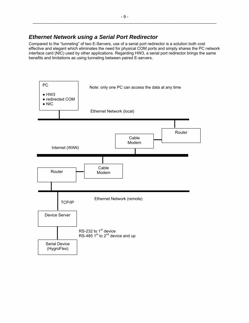
Ethernet Network using a Serial Port Redirector Compared to the “tunneling” of two E-Servers, use of a serial port redirector is a solution both cost effective and elegant which eliminates the need for physical COM ports and simply shares the PC network interface card (NIC) used by other applications. Regarding HW3, a serial port redirector brings the same benefits and limitations as using tunneling between paired E-servers.
PC Note: only one PC can access the data at any time
● HW3 ● redirected COM● NIC
Ethernet Network (local)
Serial Device (HygroFlex)
Device Server
TCP/IP Ethernet Network (remote)
Router Cable
Modem
Router Cable
Modem Internet (WAN)
RS-232 to 1st device RS-485 1st to 2nd device and up

- 10 - _________________________________________________________________________________
Compatibility requirements on a TCP/IP LAN ● IP address (Network ID and Host ID) An IP address consists of 4 numbers (1 to 3 digits each) separated with dots. On any network, each IP address should be unique. IP addresses are classified as follows: Class A: 1.x.x.x to 127.x.x.x Class B: 128.0.x.x to 191.255.x.x Class C: 192.0.0.x to 223.255.255.x In the above, x is a number between 0 and 255. Within an IP address, the network ID is defined depending on the class of the IP address and is indicated in bold in the above table. The remainder of the address is the host ID. For a class C address, the first 3 numbers define the network ID and therefore, the maximum number of hosts (or devices on the network) is limited to 256. In order for two devices in a network to communicate together, their IP address must contain the same network ID. ● Gateway Address This is the IP address of the device used to access other networks (in this case the router). ● Subnet Mask The subnet mask is used to differentiate the network ID portion of an IP address from the host ID. Class A: 255.0.0.0 Class B: 255.255.0.0 Class C: 255.255.255.0 Note: if more network ID’s are required by the network, the last number of the subnet mask can be used, but this reduces the maximum number of hosts available for each network ID. In order for two devices in the same network to communicate together, their subnet mask must be the same.
Definitions and tutorials For additional definitions provided by Software Toolbox Inc., use the following link: http://www.softwaretoolbox.com/Tech_Support/TechExpertiseCenter/Dictionary/dictionary.asp For networking tutorials provided by Lantronix, use the following link: http://www.lantronix.com/learning/tutorials/index.html
- 11 - _________________________________________________________________________________
Configuration examples using an Ethernet network
Example 1: local area network (LAN)
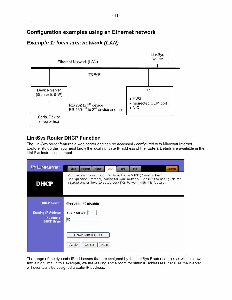
LinkSys Router DHCP Function The LinkSys router features a web server and can be accessed / configured with Microsoft Internet Explorer (to do this, you must know the local / private IP address of the router). Details are available in the LinkSys instruction manual.
The range of the dynamic IP addresses that are assigned by the LinkSys Router can be set within a low and a high limit. In this example, we are leaving some room for static IP addresses, because the iServer will eventually be assigned a static IP address.
Serial Device (HygroFlex)
Device Server (iServer EIS-W)
RS-232 to 1st device RS-485 1st to 2nd device and up
TCP/IP
Ethernet Network (LAN)
PC
LinkSys Router
● HW3 ● redirected COM port ● NIC

- 12 - _________________________________________________________________________________
Configuration of the iServer In order to ensure compatibility of the iServer with the other devices on our LAN, we have used a LinkSys router to perform the function of a DHCP server. DHCP stands for Dynamic Host Configuration Protocol. When DHCP is enabled, any new device on the network is automatically assigned a dynamic IP address, a Gateway address and a Subnet Mask. This feature saves a lot of work when devices are frequently attached to or removed from the LAN (laptops etc.). ● Enable DHCP on the iServer The iServer has an external DIP switch which is used to enable or disable DHCP (Dynamic Host Configuration Protocol). Assuming that a DHCP server exists on the LAN (for example: the LinkSys Router), set the DIP switch so as to enable DHCP. ● Initial IP address of the iServer (dynamic) Upon connecting the iServer to the LAN (with DHCP enabled), the LinkSys Router automatically gives the iServer a dynamic address, a Gateway address and a subnet mask. The router DHCP Clients Table is used to find out the new IP address of the iServer (in the table, look for the host name and MAC address of the iServer). Power off the iServer and set the dip switch on the iServer back to static IP address (DHCP disabled). The reason for this is that we will give a new (static) IP address to the iServer. ● Final IP address of the iServer (static) The iServer features a web server and can be accessed / configured with Microsoft Internet Explorer. The iServer can also be configured from its serial port with an application such as Windows HyperTerminal. In this example, we are using Internet Explorer. Knowing the initial IP address (dynamic) of the iServer, we can access the iServer configuration web page with Internet Explorer, from any PC on the LAN. The iServer is protected both by a standard user password and by an administrator’s password:
Enter 12345678 as the standard user password.
Enter 00000000 as the administrator’s password.

- 13 - _________________________________________________________________________________
The following page appears after entering the administrator’s password.
In this example, the iServer is given the static IP address: 192.168.57.200. Both the gateway address and subnet mask are left to the values assigned by the LinkSys Router. Host Name: if so desired, it is possible to register the iServer host name (eis2187) on the PC. To do this, both the host name and the IP address of the iServer should be entered in the following file: C:\Windows\System32\Drivers\Etc\HOSTS (the file HOSTS does not have any extension). This file can be opened with Notepad. Instructions are provided within the file. After registering the Host Name, the iServer can be accessed as eis2187 from Internet Explorer or pinged as eis2187.

- 14 - _________________________________________________________________________________
● Serial Communication and other Settings Go to Configuration web page and use the following settings:
The serial communication settings are in accordance with the requirements of the HygroFlex. Note the following settings: (a) End Character set to 00 (HEX), (b) forward End Character set to disabled and (c) time-out set to zero.
Terminal Server should be enabled as shown above. The number of connections (sockets) should be set to at least 1. Important: ● Be sure to write down both the IP address and the Local Port number of the i-Server (2050 in this
example). This information will be useful later on. ● To avoid conflicts, do not use port numbers used by other services such as 21 (FTP), 25 (SMTP), 80
(HTTP), 110 (POP3), etc. If necessary, check with your network administrator. In the case of the iServer, do not use port 2002 as this is used to configure the iServer. Using ports numbers in the range of 2050 and above should be safe.

- 15 - _________________________________________________________________________________
● Note that a unique port number should be assigned to each iServer connected to the same LAN. In the case of a remote LAN accessed via Internet, the value assigned to local port will be used by a Router with a registered public IP address to direct data requests to the proper iServer (non-registered private address).
● Remote Access (Tunneling) is disabled. This is used only if two iServers are communicating one with
the other.
Serial/IP Port Redirector Configuration When using the ROTRONIC HW3 software, only COM1 to COM4 are allowed, meaning that the PC should have at least one free (unused) virtual COM port in the range of 1 to 4. On the PC used in this example, both COM 1 and COM3 are physical ports. This leaves only COM2 and COM4 as virtual ports that can be used with the HW3 application.
In this example, COM2 is selected.
- 16 - _________________________________________________________________________________
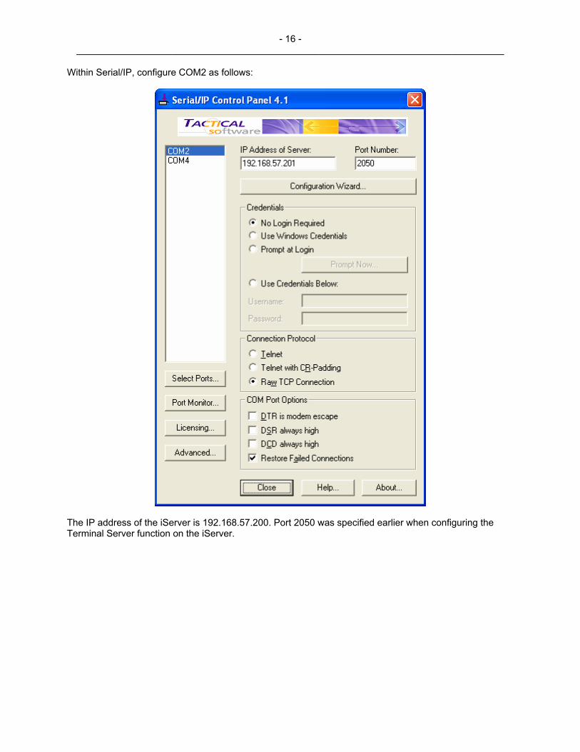
Within Serial/IP, configure COM2 as follows:
The IP address of the iServer is 192.168.57.200. Port 2050 was specified earlier when configuring the Terminal Server function on the iServer.
- 17 - _________________________________________________________________________________
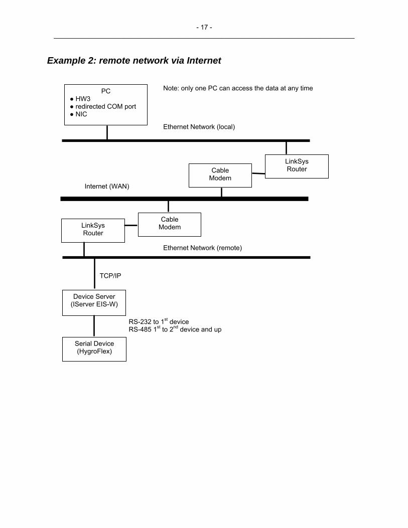
Example 2: remote network via Internet
Note: only one PC can access the data at any time PC ● HW3 ● redirected COM port ● NIC
Ethernet Network (local)
Serial Device (HygroFlex)
Device Server (IServer EIS-W)
TCP/IP
Ethernet Network (remote)
LinkSys Router
Cable Modem
LinkSys Router Cable
Modem Internet (WAN)
RS-232 to 1st device RS-485 1st to 2nd device and up

- 18 - _________________________________________________________________________________
Remote LinkSys Router Port Forwarding Accessing the remote iServer via Internet requires the use of a registered public IP address. This is the same as the public address of the remote router. Preferably, this should be a static address and getting such an address can be arranged for a fee with the ISP (Internet Service Provider) at the remote location. It is also possible to use a dynamic IP address assigned by the ISP to the remote LinkSys router, but there is a risk that this addressed may be changed down the line. Finding the public address of the remote router must typically be done at the location of the router (unless the router is configured to allow remote configuration). The LinkSys router can be accessed with Microsoft Internet Explorer (to do this, you must know the local / private IP address of the router). Details are available in the LinkSys instruction manual. The public address of the LinkSys router is listed in the WAN section of the Status page: 24.48.19.167.
24.48.19.167

- 19 - _________________________________________________________________________________
Next the router should be configured to forward to the private IP address 192.168.57.200 (IP address of the remote iServer) any outside request directed to port 2060 on the router. Note that this should be the same port that was assigned to the remote iServer, under Configuration, Terminal Server.

- 20 - _________________________________________________________________________________
Local Serial/IP Port Redirector Configuration On the local PC with Serial/IP, COM2 was configured as follows:
24.48.19.167
The public IP address of the remote router is 24.48.19.167. Requests sent to port 2060 will be forwarded by the router to the remote iServer.
Other settings All other settings are the same as described under “example 1”.

- 21 - _________________________________________________________________________________
Configuring HW3 to monitor up to 4 networks The standard (factory) configuration of HW3 is for using just one COM port (either physical or virtual / redirected). HW3 can automatically search COM 1 to 4 to detect the presence of one or several instruments. As soon as the first instrument is found, HW3 stops searching. The COM port to be used can also be manually selected. HW3 (version 2.1.2 b and above) should be reconfigured as explained below in any of the following situations: ● Two or more dedicated networks (each connected to a different physical COM port of the PC) are to be
monitored with HW3 ● Two or more non-dedicated (Ethernet) networks (each connected to a different virtual COM port of the
PC) are to be monitored with HW3 ● Any combination of the above In any case, a maximum of 4 COM ports (or networks) can be used, with a grand total of up to 32 instruments. All instruments will be displayed by HW3 in a single network form, regardless of the network to which the instruments are connected. Instructions and example: The file HW3_Sys.ini is located in the directory where HW3 was installed (usually C:\HW3). This file contains the configuration settings of HW3. This text file is in German but you can still use the line numbers as a reference. Just in case, begin by making a copy of the file as a precautionary measure. Open the HW3_Sys.ini file with a text editor such as Windows Notepad. In the file, lines in the range of 00075 to 00078 have to be edited in order to enable HW3 to monitor up to 4 separate physical networks. The original lines are as follows: "00075;RSNet 1 =aktiv 0 deaktiviert" "0" "00076;RSNet: ZweiterCom;ConnectNR(erster = original COM!!!/ConnectNr 0 darf nicht verwendet werden)" "3;31" "00077;RSNet: dritterCom;ConnectNR" "3;31" "00078;RSNet: vierterCom;ConnectNR" "3;31" As an example, we will now assume that we want to monitor the following with HW3:
- One instrument with address 00 connected to COM 1, a physical serial port on the PC (straight RS-232 connection to the PC)
- Two instruments with address 01 and 02 connected to a local Device Server, itself connected to an Ethernet LAN. The first instrument is connected by RS-232 to the Device Server and the second instrument is connected to the first by RS-485. On the PC, virtual port COM 2 is redirected (using additional software) to the PC network interface card.
- One instrument with address 04, connected to a device server at a remote location, accessible via Internet. On the PC, virtual port COM 4 is redirected and used to access the remote Device Server.

- 22 - _________________________________________________________________________________
The above example is equivalent to 3 separate networks. To enable HW3 to monitor these networks, proceed as follows: a) Go to line 00075: "00075;RSNet 1 =aktiv 0 deaktiviert" "0" Change the line immediately following line 00075 to: “1” This enables HW3 to monitor several COM ports or networks b) Go to line 00076: "00076;RSNet: ZweiterCom;ConnectNR(erster = original COM!!!/ConnectNr 0 darf nicht verwendet werden)" "3;31" Change the line immediately following line 00076 to: “2;1” This tells HW3 to look for instruments on COM 2, starting with address 01 and ending one address before the address specified under c). In this example, HW3 will look for addresses 01, 02 and 03 on COM 2. Note that HW3 will look for an instrument with address 00 on COM1. If no such instrument exits, HW3 will show a blank line as the first line of the network display form. c) Go to line 00077: "00077;RSNet: dritterCom;ConnectNR" "3;31" Change the line immediately following line 00077 to: “4;4” This tells HW3 to look for instruments on COM 4, starting with address 04 and ending one address before the address specified under d). In this example, HW3 will look for addresses 04 to 31 on COM 4. Note that COM 3 was skipped and that it will not be used. c) Go to line 00078: "00078;RSNet: vierterCom;ConnectNR" "3;31" Change the line immediately following line 00077 to: “5;32” This tells HW3 to look for instruments on COM 5, starting with address 32. Note that both COM 5 and address 32 cannot be used by HW3. If only COM port 1 and 2 had been used in the example, the text “3;32” would have been used immediately after lines 00077 and 00078. Similarly, if only COM 1 to 3 had been used in the example, the text “4;32” would have been used immediately after line 00078.

- 23 - _________________________________________________________________________________
Important: ● Prior to connecting the instruments, be sure to configure each instrument to have a unique address,
even if the instruments are connected to separate networks ● COM 1 is always used by HW3 and address 00 cannot be associated with any other COM port. If no
instrument is connected to COM 1, address 00 is lost and the total number of instruments that HW3 can monitor is reduced from 32 to 31.
● HW3 is limited to COM 1, 2, 3 and 4. Any of these COM ports can be a physical or a virtual (redirected)
port. In the HW3 configuration file, COM ports 2 to 4 should be declared in ascending order. Any unused port other than COM1 can be skipped (COM 1 is implicit).
● Instrument addresses should always be assigned to the different COM ports in ascending order. For
example, COM 2 should be assigned a lower range of addresses than COM 3. Instruments should be connected to the networks / Device Servers so as to agree with the COM port assignment. HW3 will automatically skip a non existent address.
● Do not change the text of lines 00075 to 00078
Extent of the support provided by ROTRONIC The support provided by ROTRONIC is limited to providing information relative to the ROTRONIC serial products and to the HW3 software. The installation and configuration of the COM port redirector and Device Servers is the responsibility of the customer. ROTRONIC does not sell COM port redirector software and Device Servers, but may recommend certain products.