Technical ommunications ulletin T 18 - snorkellifts.com · [email protected]...
6
1 TCB 18.015 Date: June 5, 2018 Read and fully understand this Technical Communicaons Bullen before beginning. Follow instrucons completely. If you should have any quesons or concerns regarding this Technical Communicaons Bullen, please contact your regional Snorkel Product Support Department. Priority Status: P1: Needs completed at your earliest opportunity P2: Needs completed at the next service X P3: Product improvement completed as needed P4: Instrucons only TCB 18.015 This procedure applies to all machines with an enable switch operated joysck. The purpose of this bullen is to install a joy- sck trigger guard. To determine the correct Snorkel kit for your joysck please see the opons shown in the figures below. These kits can be ordered by contacng the Snorkel Parts Department. This procedure is a Product Improvement Only. All parts and labor will be at the customer expense. This procedure will take approximately 30 minutes to perform. ECRN 2018-0392 Rev A Tools Required: Phillip's screwdriver, standard screwdriver, Torx driver, soldering kit, needle nose pliers Snorkel kit needed: 3028934 Technical Communicaons Bullen Snorkel kit needed: 3028935 Large hex opening Small round hole Ribbed back plate Smooth back plate
Transcript of Technical ommunications ulletin T 18 - snorkellifts.com · [email protected]...
1 TCB 18.015
Date: June 5, 2018
Read and fully understand this Technical Communications Bulletin before beginning. Follow instructions completely. If
you should have any questions or concerns regarding this Technical Communications Bulletin, please contact your regional
Snorkel Product Support Department.
Priority Status:
P1: Needs completed at your earliest opportunity
P2: Needs completed at the next service
X P3: Product improvement completed as needed
P4: Instructions only
TCB 18.015
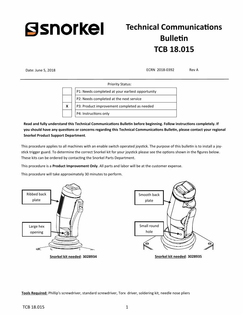
This procedure applies to all machines with an enable switch operated joystick. The purpose of this bulletin is to install a joy-
stick trigger guard. To determine the correct Snorkel kit for your joystick please see the options shown in the figures below.
These kits can be ordered by contacting the Snorkel Parts Department.
This procedure is a Product Improvement Only. All parts and labor will be at the customer expense.
This procedure will take approximately 30 minutes to perform.
ECRN 2018-0392 Rev A
Tools Required: Phillip's screwdriver, standard screwdriver, Torx driver, soldering kit, needle nose pliers
Snorkel kit needed: 3028934
Technical Communications
Bulletin
Snorkel kit needed: 3028935
Large hex
opening
Small round
hole
Ribbed back
plate
Smooth back
plate
2 TCB 18.015
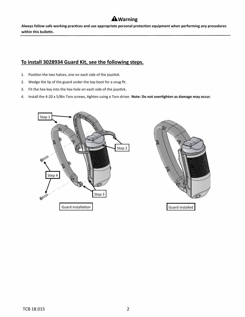
To install 3028934 Guard Kit, see the following steps. 1. Position the two halves, one on each side of the joystick.
2. Wedge the lip of the guard under the top boot for a snug fit.
3. Fit the hex key into the hex hole on each side of the joystick.
4. Install the 4-20 x 5/8in Torx screws, tighten using a Torx driver. Note: Do not overtighten as damage may occur.
Always follow safe working practices and use appropriate personal protection equipment when performing any procedures
within this bulletin.
Warning
Step 1
Step 2
Step 3
Step 4
Guard installed Guard installation
3 TCB 18.015
To install 3028935 Guard Kit, see the following steps.
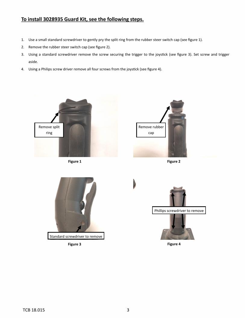
1. Use a small standard screwdriver to gently pry the split ring from the rubber steer switch cap (see figure 1).
2. Remove the rubber steer switch cap (see figure 2).
3. Using a standard screwdriver remove the screw securing the trigger to the joystick (see figure 3). Set screw and trigger
aside.
4. Using a Philips screw driver remove all four screws from the joystick (see figure 4).
Figure 1 Figure 2
Remove split
ring
Remove rubber
cap
Figure 3 Figure 4
Standard screwdriver to remove
Phillips screwdriver to remove
4 TCB 18.015
Figure 5 Figure 6
Figure 7 Figure 8
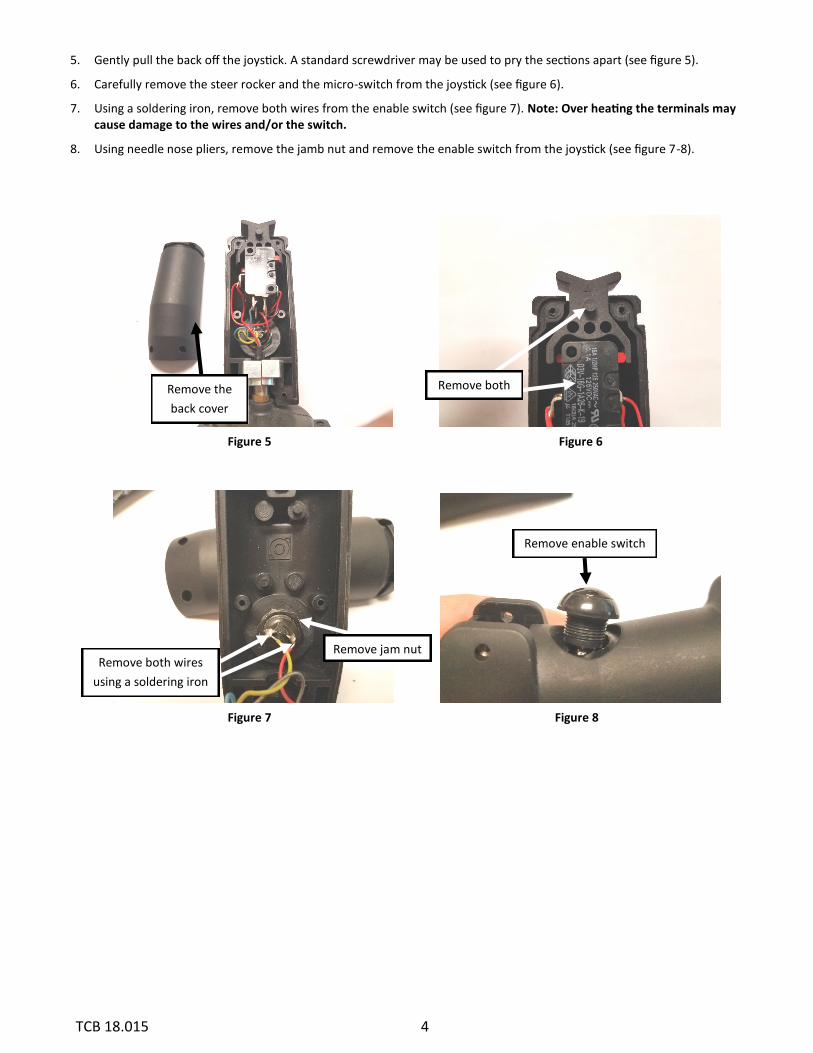
5. Gently pull the back off the joystick. A standard screwdriver may be used to pry the sections apart (see figure 5).
6. Carefully remove the steer rocker and the micro-switch from the joystick (see figure 6).
7. Using a soldering iron, remove both wires from the enable switch (see figure 7). Note: Over heating the terminals may cause damage to the wires and/or the switch.
8. Using needle nose pliers, remove the jamb nut and remove the enable switch from the joystick (see figure 7-8).
Remove enable switch
Remove the
back cover
Remove both
Remove both wires
using a soldering iron
Remove jam nut
5 TCB 18.015
Figure 12 Figure 11
Figure 10 Figure 9
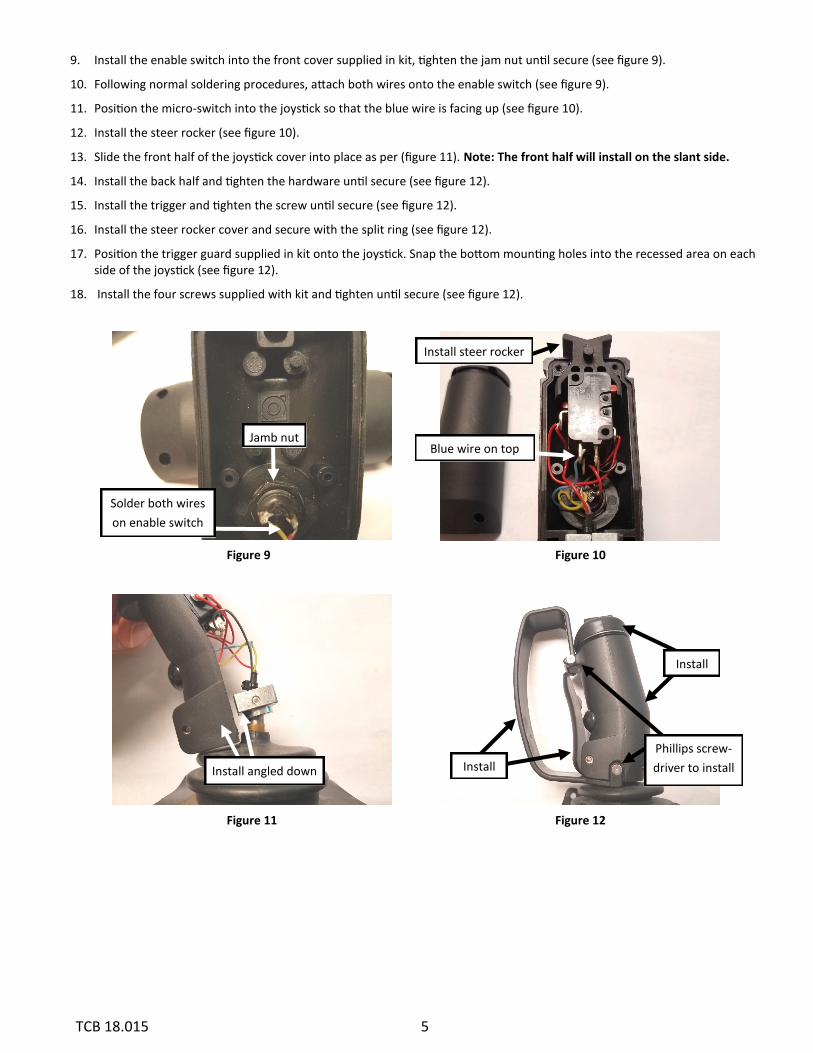
9. Install the enable switch into the front cover supplied in kit, tighten the jam nut until secure (see figure 9).
10. Following normal soldering procedures, attach both wires onto the enable switch (see figure 9).
11. Position the micro-switch into the joystick so that the blue wire is facing up (see figure 10).
12. Install the steer rocker (see figure 10).
13. Slide the front half of the joystick cover into place as per (figure 11). Note: The front half will install on the slant side.
14. Install the back half and tighten the hardware until secure (see figure 12).
15. Install the trigger and tighten the screw until secure (see figure 12).
16. Install the steer rocker cover and secure with the split ring (see figure 12).
17. Position the trigger guard supplied in kit onto the joystick. Snap the bottom mounting holes into the recessed area on each side of the joystick (see figure 12).
18. Install the four screws supplied with kit and tighten until secure (see figure 12).
Install steer rocker
Blue wire on top
Solder both wires
on enable switch
Install angled down
Install
Install
Jamb nut
Phillips screw-
driver to install
6 TCB 18.015
For Further Information in North and South America
Contact the Snorkel Service Department at:
Phone: 1-800-255-0317 or 1-785-989-3091
Fax: 1-785-989-3075
Or contact the Snorkel Service Department via email at:
Further Information in EMEA
Contact the Snorkel Service Department at:
Phone: +44 (0) 191 4616909 / +44 (0) 191 4616910
Or contact Technical Support via email at:
For Further Information in Australia
Contact the Snorkel Service Department at:
Phone: 1300 700 450
Or contact Technical Support via email at:
For Further Information in Asia Pacific
Contact the Snorkel Service Department at:
Phone: 03-5765-6841
Or contact Technical Support via email at:
Fun Fook Wai : [email protected]
For further Information in Asia (Japan)
Contact the Snorkel Service Department at:
Phone: 03-5765-6841
Or contact Technical Support via email at: