Technical Note - TN 086: 2015...Technical Note - TN 049: 2015 . 3.2. Sign off box . The sign off box...
93
Technical Note - TN 086: 2015 © State of NSW through Transport for NSW Page 1 of 1 Technical Note - TN 086: 2015 Subject: Withdrawal of TMD 0001 CAD Manual- All sections (except Section 5 – Electrical Operating Diagrams) Issued date: 01 March 2016 Effective date: 01 March 2016 This technical note is issued by the Asset Standards Authority as a notification to remove from use the RailCorp standard TMD 0001 CAD Manual- All sections, Version 2.3 (except section 5 – Electrical operating diagrams). TMD 0001 CAD Manual- All sections (except section 5 – Electrical operating diagrams) are legacy documents and shall be used for reference purposes only. ASA standard T MU MD 00006 ST Engineering Drawings and CAD Requirements, Version 1.0 supersedes this document from 01 March 2016. Authorisation: Technical content prepared by Checked and approved by Interdisciplinary coordination checked by Authorised for release Signature Date Name Harpreet Singh Jagath Peiris John Paff Graham Bradshaw Position CAD Specialist Manager Network Standards A/Chief Engineer Rail Director Network Standards and Services For queries regarding this document [email protected] www.asa.transport.nsw.gov.au
Transcript of Technical Note - TN 086: 2015...Technical Note - TN 049: 2015 . 3.2. Sign off box . The sign off box...
Technical Note - TN 086: 2015
© State of NSW through Transport for NSW Page 1 of 1
Technical Note - TN 086: 2015
Subject: Withdrawal of TMD 0001 CAD Manual- All sections (except Section 5 – Electrical Operating Diagrams)
Issued date: 01 March 2016
Effective date: 01 March 2016
This technical note is issued by the Asset Standards Authority as a notification to remove from
use the RailCorp standard TMD 0001 CAD Manual- All sections, Version 2.3 (except section 5 –
Electrical operating diagrams).
TMD 0001 CAD Manual- All sections (except section 5 – Electrical operating diagrams) are
legacy documents and shall be used for reference purposes only. ASA standard
T MU MD 00006 ST Engineering Drawings and CAD Requirements, Version 1.0 supersedes this
document from 01 March 2016.
Authorisation:
Technical content prepared by
Checked and approved by
Interdisciplinary coordination checked by
Authorised for release
Signature
Date
Name Harpreet Singh Jagath Peiris John Paff Graham Bradshaw
Position CAD Specialist Manager Network Standards
A/Chief Engineer Rail Director Network Standards and Services
For queries regarding this document [email protected]
www.asa.transport.nsw.gov.au

Technical Note - TN 049: 2015
Technical Note - TN 049: 2015
Subject: Update to TMD 0001 CAD and Drafting Manual - Drawing title block update
Issued date: 21 August 2015
Effective date: 21 August 2015
For queries regarding this document [email protected]
www.asa.transport.nsw.gov.au
1. Purpose
This technical note is issued by the Asset Standards Authority (ASA) to update the title block
requirements, for all rail asset drawings created for TfNSW, in TMD 0001 CAD and Drafting
Manual, version 2.3.
The requirements of this technical note will be incorporated into T MU MD 00006 ST Engineering
Drawings and CAD Requirements that is currently under development.
Requirements in this technical note will supersede requirements set in Section 1.11.2 of
TMD 0001 CAD and Drafting manual.
2. Application
The requirements described in this technical note are mandatory to all technical drawings
produced for Transport for NSW (TfNSW) under contracts entered on or after the effective date of
this technical note.
Where a contract to deliver technical drawings was executed prior to the issue of this technical
note, the AEO should attempt to comply with these requirements where there is no or negligible
cost impact to do so.
3. Drawing title block
The title block setting and filling in shall comply with the procedure explained in Section 3.1,
Section 3.2 and Section 3.3. Figure 1 shows an example of typical drawing sheet template, which
consists of three components.
© State of NSW through Transport for NSW Page 1 of 8 Sup
erse
ded
by T
MU
MD
000
06 S
T v1
.0

Technical Note - TN 049: 2015
These components are categorised as follows:
• drawing details box
• sign-off box
• amendment box
Figure 1 – Typical TfNSW drawing sheet template
© State of NSW through Transport for NSW Page 2 of 8 Sup
erse
ded
by T
MU
MD
000
06 S
T v1
.0
Technical Note - TN 049: 2015
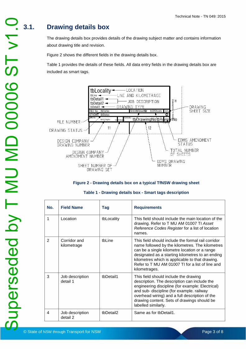
3.1. Drawing details box
The drawing details box provides details of the drawing subject matter and contains information
about drawing title and revision.
Figure 2 shows the different fields in the drawing details box.
Table 1 provides the details of these fields. All data entry fields in the drawing details box are
included as smart tags.
Figure 2 - Drawing details box on a typical TfNSW drawing sheet
Table 1 - Drawing details box - Smart tags description
No. Field Name Tag Requirements
1 Location tbLocality This field should include the main location of the drawing. Refer to T MU AM 01007 TI Asset Reference Codes Register for a list of location names.
2 Corridor and kilometrage
tbLine This field should include the formal rail corridor name followed by the kilometres. The kilometres can be a single kilometre location or a range designated as a starting kilometres to an ending kilometres which is applicable to that drawing. Refer to T MU AM 01007 TI for a list of line and kilometrages.
3 Job description detail 1
tbDetail1 This field should include the drawing description. The description can include the engineering discipline (for example: Electrical) and sub- discipline (for example. railway overhead wiring) and a full description of the drawing content. Sets of drawings should be labelled similarly.
4 Job description detail 2
tbDetail2 Same as for tbDetail1.
© State of NSW through Transport for NSW Page 3 of 8 Sup
erse
ded
by T
MU
MD
000
06 S
T v1
.0

Technical Note - TN 049: 2015
No. Field Name Tag Requirements
5 Drawing type tbDetail3 This field should indicate the type of drawing; for example, alignment, cover sheet, survey, plan, sections, note, schematic diagram and so on.
6 File Number tbFileNo This field is optional and the entry is based on the design company to assist the tracking of drawings within their own system.
7 Drawing status tbStatus This field should indicate the status of the revision of the drawing. Allowable values are tender, contract, concept design, reference design, design, approved for construction and as-built.
Note: The status shall not be additionally stamped elsewhere on the drawing.
8 Sheet number tbSheetNo This field should indicate the sheet number of a drawing in a set of drawings. Where there are no other drawings in the set, the particular sheet is sheet 1.
9 Total number of sheets
tbOfSheets This field should indicate the total number of sheets in a set in which this drawing forms part of. Where there are no other drawings in the set, this sheet is numbered 1.
10 EDMS number. tbDrawingNo This field should include the TfNSW drawing number (2 alphabets and 7 numbers) provided to the designer by TfNSW (in consultation with the Central Planroom), and is unique for each drawing.
11 EDMS amendment status (Revision associated with EDMS number)
tbRevisionNo This field should indicate the TfNSW revision, which is related to the EDMS number and shall be changed only when the drawings are submitted to Central Planroom. The first instance of the drawing shall always show as ‘A’ in this box.
12 Sheet size tbSheetSize This field should indicate the size of the drawing.
13 Design Company drawing number
tbAEODrgNo This field should include the design company drawing number.
14 Design Company revision status
tbAEORevNo This field should indicate the drawing revision related to the design company.
The fields in the drawing details box are a combination of either free text or pick list (pre- defined)
items. For fields with ‘free text’, information shall conform to the following principles:
• Drawing titles shall be correct, comprehensive and compliant with the formats indicated.
• Abbreviations should be avoided but common construction abbreviations are allowed (for
example, LV, OHW, DRG, ULX and so on) or ones that are explained on the drawing.
• The drawing title is made up of the five lines (location, line and kilometrage, job description
detail 1 and detail 2 and drawing type) and shall contain specific information about the
content of the drawing. Once a drawing is submitted to Central Planroom, drawing title shall
not be modified in future amendments.
© State of NSW through Transport for NSW Page 4 of 8 Sup
erse
ded
by T
MU
MD
000
06 S
T v1
.0
Technical Note - TN 049: 2015
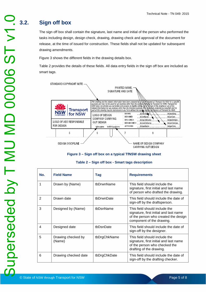
3.2. Sign off box
The sign off box shall contain the signature, last name and initial of the person who performed the
tasks including design, design check, drawing, drawing check and approval of the document for
release, at the time of issued for construction. These fields shall not be updated for subsequent
drawing amendments.
Figure 3 shows the different fields in the drawing details box.
Table 2 provides the details of these fields. All data entry fields in the sign off box are included as
smart tags.
Figure 3 – Sign off box on a typical TfNSW drawing sheet
Table 2 – Sign off box - Smart tags description
No. Field Name Tag Requirements
1 Drawn by (Name) tbDrwnName This field should include the signature, first initial and last name of person who drafted the drawing.
2 Drawn date tbDrwnDate This field should include the date of sign-off by the draftsperson.
3 Designed by (Name) tbDsnName This field should include the signature, first initial and last name of the person who created the design component of the drawing.
4 Designed date tbDsnDate This field should include the date of sign-off by the designer.
5 Drawing checked by (Name)
tbDrgChkName This field should include the signature, first initial and last name of the person who checked the drafting of the drawing.
6 Drawing checked date tbDrgChkDate This field should include the date of sign-off by the drafting checker.
© State of NSW through Transport for NSW Page 5 of 8 Sup
erse
ded
by T
MU
MD
000
06 S
T v1
.0

Technical Note - TN 049: 2015
No. Field Name Tag Requirements
7 Design checked by (Name)
tbDsnChkName This field should include the signature, first initial and last name of person who checked the design component of the drawing.
8 Design checked date tbDsnChkDate This field should include the date of sign-off by design checker.
9 Approver (Name) tbApprName This field should include the signature, first initial and last name of person who approved the design to be released.
10 Approved date tbApprDate This field should include the date of sign-off by design approver.
11 Design discipline tbDiscipline This field should include the discipline to which the drawing relates.
12 Design company name tbAEOSuppName This field is the name of the design company.
3.3. Amendment box
The amendment box records the details of all formal issues of a drawing. Details include TfNSW
EDMS amendment status or the AEO revision status, grid reference for the last change,
amendment description along with the initials of the designer, verifier and approver.
'AMD' column records the amendment status of the drawing.
A brief but informative description of the changes made to the drawing shall be added to
'Description' column, such as, issued for review, issued for comments, approved for construction
and as-built. The initials of the designer, verifier and approver shall be placed in the amendment
box for each drawing issue.
Where possible at least three letters for initials are required to minimize the possibility of
misidentification of approvers with common first initial and last initial.
The oldest amendment entries shall be displayed at the bottom of the list. Amendment history
items should only be removed when all available lines have been used. In this case, the oldest
amendment information is removed and the rest of the entries are moved down to create room for
the new amendment at the top of the list.
Figure 4 shows the different fields in the amendment box.
Table 3 provides the details of these fields. All data entry fields in the amendment box are
included as smart tags.
© State of NSW through Transport for NSW Page 6 of 8 Sup
erse
ded
by T
MU
MD
000
06 S
T v1
.0

Technical Note - TN 049: 2015
Figure 4 - Amendment box on a standard TfNSW drawing sheet
Table 3 – Amendment box - Smart tags
No. Field name Tag Requirements
1 Coordinate System tbCoordSys This is an optional field.
This is required for drawings containing survey co-ordinates.
2 Height datum tbHghtDatum This is an optional field. This is required for drawings containing survey co-ordinates,
3 Scale tbScale This is the major scale of a drawing.
4 Amendment status tbAMDNo This field should indicate the amendment status of current revision.
5 Grid reference tbAMDRef This field should include the drawing grid reference of the amendment. For example, G5; H10.
6 Amendment description
tbAMDDesc This field should contain a brief description of the phase of review or approval that the drawing is issued.
7 Amendment designer Sign
tbAMDDsgnSign This field should include the initials of the person who designed the amendment.
8 Amendment designer date
tbAMDDsgnDate This field should include the date when the designer signed the revision.
9 Amendment verifier sign
tbAMDVerSign This field should include the initials of the person who verified the amendment.
10 Amendment verifier date
tbAMDVerDate This field should include the date when the verifier verified and signed the amendment.
11 Amendment approver sign
tbAMDApprSign This field should include the initials of the person who approved the amendment.
12 Amendment approver date
tbAMDApprDate This field should include the date when the approver approved the amended design.
© State of NSW through Transport for NSW Page 7 of 8 Sup
erse
ded
by T
MU
MD
000
06 S
T v1
.0

Technical Note - TN 049: 2015
Authorisation:
Technical content prepared by
Checked and approved by
Interdisciplinary coordination checked by
Authorised for release
Signature
Name Harpreet Singh Jagath Peiris Ken Kwan Ken Kwan
Position CAD Specialist Manager, Network Standards
A/Principal Manager, Network Standards and Services
A/Principal Manager, Network Standards and Services
© State of NSW through Transport for NSW Page 8 of 8 Sup
erse
ded
by T
MU
MD
000
06 S
T v1
.0

Technical Note - TN 026: 2015
© State of NSW through Transport for NSW Page 1 of 4
Technical Note - TN 026: 2015
Subject: Submission of drawings to the Virtual Planroom (VPR)
Issued date: 07 May 2015
Effective date: 07 May 2015
For queries regarding this document [email protected]
www.asa.transport.nsw.gov.au
1. Background
The Virtual Planroom (VPR) is an engineering document repository currently managed by
Sydney Trains. To submit drawings to this repository, drawings need to meet applicable
engineering drawing and submission requirements as outlined in TMD 0001 CAD and Drafting
Manual.
This technical note is issued to expand on the requirements of TMD 0001. The additional
requirements in this technical note reflect existing practice.
Requirements stated assist management and future retrieval of the drawings.
Custodians of VPR (Sydney Trains planroom staff) may check compliance to the requirements
in Section 3, Section 4, and Section 5. The planroom staff may reject submissions that fail to
meet these requirements or if they are outside the scope of the VPR repository.
Failure of a party to deliver drawings that comply with requirements outside the above may
result in the non-compliance being reported for further investigation but the drawings will not be
rejected by VPR custodians.
2. Application
The requirements described in this technical note are mandatory to engineering drawings
delivered as part of a contract to TfNSW executed after the date of issue of this technical note.
Where a contract to deliver engineering drawings was executed prior to the issue of this
technical note, the party delivering the images should attempt to comply with these
requirements where there is no impact or negligible impact to do so. TfNSW project directors
and project managers should attempt to have contractors under their management comply
where practical.
Sup
erse
ded
by T
MU
MD
000
06 S
T v1
.0

Technical Note - TN 026: 2015
© State of NSW through Transport for NSW Page 2 of 4
3. Requirements for images submitted
All images submitted to the VPR shall comply with the requirements below:
• PDF and TIF files shall be created as size 1 to 1 (1:1) so as to be printable by default at the
intended size
• images shall be printable and viewable with no password protection
• images provided as PDF files shall have document layers flattened so that the document is
a single page document
• images shall comply with the file name requirements detailed in Section 6.1 of this
technical note
• images shall comply with orientation requirements detailed in Section 6.2 of this technical
note
4. Requirements for data submitted with images
All images submitted to the VPR shall be accompanied by the data listed below. Explanations of
data requirements are in TMD 0001 or Section 6.
• engineering discipline
• EDMS ID
• amendment level
• amendment date
• title (See Section 6.3)
• document purpose
• supplier name (See Section 6.4)
• supplier's document number (See Section 6.5)
• size
• sheet number
• total sheets
• document set name (See Section 6.6)
The above data shall be provided in an Excel spread sheet format using the drawing data fields
template unless other arrangements have been agreed to by the custodians of the VPR system.
The drawing data fields template is available in the external references section of VPR for
parties with direct access or otherwise on request from the custodians of VPR,
5. Folder structure for submissions
Electronic drawing files and associated information shall be submitted in a folder that identifies
the project. Sub-folders shall be created as described below:
• completed drawing data fields template shall be placed in a sub-folder titled "Other" along
with any files that apply to the submission as a whole, such as cover letters
Sup
erse
ded
by T
MU
MD
000
06 S
T v1
.0

Technical Note - TN 026: 2015
© State of NSW through Transport for NSW Page 3 of 4
• CAD files shall be placed in a sub-folder titled "CAD"
• rendered image files shall be placed in a sub-folder titled "Renditions"
6. Explanation of requirements
The following sections provide explanations of requirements listed in Section 2 and Section 3
that are not described in TMD 0001 CAD and Drafting Manual or that require additional
clarification.
6.1 Filename requirements for images
Image files shall be named as per the individual Engineering Document Management System
Identification (EDMS ID) number which is assigned to each drawing.
Image filenames shall be structured as follows:
• the first seven characters shall be the EDMS ID number allocated to the drawing
• characters eight and nine are an alpha-numeric representation of the amendment level of
the drawing. When the amendment level is only one character, then character eight shall
be an underscore and character nine shall be the amendment level.
• character ten shall always be zero ('0')
• character eleven shall be a lower case 'c' for landscape orientation images and be an
upper case 'C' for portrait orientation
• the extension of the file name shall match the file type and be in lower case (for example tif
or pdf)
Examples of valid filenames are shown as follows:
• 1234567_A0c.tif
• 0279239_B0C.pdf
6.2 Orientation requirements for images
All images on sheet sizes A1 and smaller shall be produced so that the drawing is in the correct
orientation when displayed on a screen.
All drawings of a size greater than A1 are to be produced in portrait page orientation with the
longest side of the drawing orientated on the left hand side of the image.
6.3 Title requirement
The title applied in the drawing data fields spread sheet shall be identical to that within the title
block of the image. The requirements of the title block are defined in TMD 0001.
6.4 Supplier name requirement
The supplier name is the name of the organisation supplying the document.
Sup
erse
ded
by T
MU
MD
000
06 S
T v1
.0

Technical Note - TN 026: 2015
© State of NSW through Transport for NSW Page 4 of 4
6.5 Supplier's document number
The supplier's document number is the document reference number used by the organisation
supplying the document.
6.6 Document set name requirement
The document identifies when a range of EDMS ID numbers belong to a single document set.
The document set value for a document set is the discipline concatenated with the EDMS ID
assigned to the first page.
For example, if three pages of a civil engineering drawing set have EDMS ID values of
0000101, 0000102, and 0000103 then the document set value for all three pages is
CV0000101.
Authorisation:
Technical content prepared by
Checked and approved by
Interdisciplinary coordination checked by
Authorised for release
Signature
Name Garry Thong Jagath Peiris Graham Bradshaw Graham Bradshaw
Position Manager Asset Configuration Systems
Manager Network Standards
Principal Manager, Network Standards and Services
Principal Manager, Network Standards and Services
Sup
erse
ded
by T
MU
MD
000
06 S
T v1
.0

CAD AND DRAFTING MANUAL - ALL DESIGN AREAS –
SECTIONS 1 AND 2
TMD 0001
Engineering Manual Design General
Version 2.3
Issued May 2013
Owner: Applications Manager – RailCAD
Approved by:
Brent Mallam Applications Manager RailCAD
Authorised by:
Philip Pearce General Manager Chief Engineers’ Division E
ng
inee
rin
g M
anu
al
Disclaimer
This document was prepared for use on the RailCorp Network only.
RailCorp makes no warranties, express or implied, that compliance with the contents of this document shall be sufficient to ensure safe systems or work or operation. It is the document user’s sole responsibility to ensure that the copy of the document it is viewing is the current version of the document as in use by RailCorp.
RailCorp accepts no liability whatsoever in relation to the use of this document by any party, and RailCorp excludes any liability which arises in any manner by the use of this document.
Copyright
The information in this document is protected by Copyright and no part of this document may be reproduced, altered, stored or transmitted by any person without the prior consent of RailCorp.
UNCONTROLLED WHEN PRINTED Page 1 of 80
Sup
erse
ded
by T
MU
MD
000
06 S
T v1
.0

RailCorp Engineering Manual — Design — General CAD and Drafting Manual - All Design Areas – Sections 1 and 2 TMD 0001
© RailCorp Page 2 of 80 Issued May 2013 UNCONTROLLED WHEN PRINTED Version 2.3
Document control
Version Date Summary of change 1.0 Aug 2005 First issue 1.1 Aug 2005 Section numbering updated, Reference corrections and
Document 1.2 Sept 2005 Alteration after stake holder review 1.3 Sept 2005 Error in section numbering corrected 1.4 Jan 2006 Title Block statement added – Figures 1.11.2A & B 2.0 April 2009 Major review. Re-formatted and renumbered to new
system. Cell libraries and level names revised. 2.1 Aug 2009 Alteration after stake holder review 2.2 September 2010 Application of TMA 400 format 2.3 May 2013 Section 1.4 Figure 3 – Colour Table updated.
Section 1.11.2 Title Blocks – “Signatories Box” updated to include Technical Note ATN 12/08. Section 1.11.3 Tags – updated to include Technical Note ATN 12/01. Section 1.15.4 Use of Colour on Drawings - updated to include Technical Note ATN 12/01. Section 1.15.5 Design History - updated to include Technical Note ATN 12/01.
Sup
erse
ded
by T
MU
MD
000
06 S
T v1
.0
RailCorp Engineering Manual — Design — General CAD and Drafting Manual - All Design Areas – Sections 1 and 2 TMD 0001
Contents
© RailCorp Page 3 of 80 Issued May 2013 UNCONTROLLED WHEN PRINTED Version 2.3
1 Standards Affecting All Design Areas ..................................................................................6 1.1 Introduction ................................................................................................................6 1.2 Linework ....................................................................................................................6 1.3 Line styles..................................................................................................................6
1.3.1 Standard Line Styles ..................................................................................6 1.3.2 Custom Line Styles ....................................................................................7
1.4 Colour ........................................................................................................................8 1.5 Text ............................................................................................................................9
1.5.1 MicroStation V8 Text Styles .......................................................................9 1.5.2 Fonts...........................................................................................................9 1.5.3 Height and Line Weight of Text................................................................11
1.6 Cell Libraries for General Application ......................................................................12 1.7 Levels, Level Symbology Overrides and Symbology ByLevel ................................12 1.8 Seed Files................................................................................................................12 1.9 Design File Structure ...............................................................................................12
1.9.1 Drawing Files............................................................................................12 1.9.2 DGM Model Files......................................................................................13
1.10 Drawings..................................................................................................................13 1.11 Drawing Standards ..................................................................................................13
1.11.1 Drawing Sheets ........................................................................................13 1.11.2 Title Blocks ...............................................................................................13 1.11.3 Tags..........................................................................................................18 1.11.4 Coordination Between Sections ...............................................................26 1.11.5 Orientation................................................................................................26 1.11.6 Coordinates & Bearings ...........................................................................26 1.11.7 Track Kilometrages ..................................................................................27 1.11.8 Layout.......................................................................................................27 1.11.9 Headings ..................................................................................................27 1.11.10 Sections....................................................................................................27 1.11.11 Details.......................................................................................................28 1.11.12 Materials Symbology................................................................................28 1.11.13 Scales Of Drawings..................................................................................28
1.12 Dimensioning ...........................................................................................................29 1.12.1 General.....................................................................................................29 1.12.2 Dimension Lines.......................................................................................29 1.12.3 Dimension Text ........................................................................................31
1.13 Gradients & Batters .................................................................................................31 1.13.1 Gradients..................................................................................................31 1.13.2 Batters ......................................................................................................32
1.14 Abbreviations ...........................................................................................................32 1.14.1 Common Abbreviations............................................................................32
1.15 Notes, References and Locality Diagrams ..............................................................34 1.15.1 General.....................................................................................................34 1.15.2 Notes ........................................................................................................35
Sup
erse
ded
by T
MU
MD
000
06 S
T v1
.0
RailCorp Engineering Manual — Design — General CAD and Drafting Manual - All Design Areas – Sections 1 and 2 TMD 0001
© RailCorp Page 4 of 80 Issued May 2013 UNCONTROLLED WHEN PRINTED Version 2.3
1.15.3 References ...............................................................................................35 1.15.4 Use of colour on drawings........................................................................36 1.15.5 Use of Design History feature on MicroStation CAD files ........................37
1.16 Product Specification...............................................................................................37
2 Location Plans and Details Site Plans ................................................................................37 2.1 Location Plans .........................................................................................................38 2.2 Detailed Site Plans ..................................................................................................38
Appendix A Cell Libraries for General Application.................................................................40
Appendix B CADD Level Structure ...........................................................................................41 1.1 Global Level Structure .............................................................................................41
1.1.1 Levels that are generic to all of Design within the RailCAD System .....................................................................................................41
1.1.2 Current Design Level Structure................................................................42 1.1.3 Field Data Level Structure........................................................................43
Appendix C CAD File Naming Conventions.............................................................................57 1.1 Overview..................................................................................................................57
1.1.1 Definitions.................................................................................................57 1.1.2 CAD File Naming Format .........................................................................58
1.1.2.1 The standard CAD file name is defined by 7 main components that give the name some visual intelligence. ...............................................................................58
1.1.2.2 Discipline Component ...............................................................58 1.1.2.3 Type Component ......................................................................58 1.1.2.4 File Identifier Component..........................................................58 1.1.2.5 Amendment Component ...........................................................58 1.1.2.6 File Purpose Component ..........................................................59 1.1.2.7 Optional Detail Component.......................................................59 1.1.2.8 File Extension ...........................................................................59
1.1.3 CAD Projects............................................................................................59 1.1.3.1 CAD Project Identifier Format...................................................59 1.1.3.2 CAD Project Naming Format ....................................................60
1.1.4 InRail Model File Types............................................................................61 1.1.4.1 Introduction ...............................................................................61 1.1.4.2 Digital Terrain Model (Surface Files) File Naming
Format.......................................................................................61 1.1.4.3 Geometry Model (Alg) File Naming Format ..............................62
1.1.5 MicroStation Levels ..................................................................................63 1.1.5.1 Overview ...................................................................................63 1.1.5.2 CAD DGN Library Naming Format ...........................................63 1.1.5.3 CAD Level Naming Format.......................................................63
1.1.6 Part A – File Name extensions for CAD Related Files (Table 8) ..............................................................................................................64
1.1.7 Part B - Design Discipline Codes (Table 9)..............................................66 1.1.8 Part C – Document Purpose Codes (Table 10) .......................................66 1.1.9 Part D – CAD Drawing File Types (Table 11) ..........................................66
1.1.9.1 Global (General) Drawing Type Listing Codes .........................66
Sup
erse
ded
by T
MU
MD
000
06 S
T v1
.0
RailCorp Engineering Manual — Design — General CAD and Drafting Manual - All Design Areas – Sections 1 and 2 TMD 0001
© RailCorp Page 5 of 80 Issued May 2013 UNCONTROLLED WHEN PRINTED Version 2.3
1.1.9.2 Architectural Drawing Type Listing Codes................................67 1.1.9.3 Bridges and Structures Drawing Type Listing
Codes........................................................................................67 1.1.9.4 Electrical Drawing Type Listing Codes .....................................69 1.1.9.5 Mechanical Drawing File Type Listing Codes...........................70 1.1.9.6 Signal Drawing Type Listing Codes..........................................70 1.1.9.7 Survey Drawing File Type Listing Codes..................................71 1.1.9.8 Track Drawing Type Listing Codes...........................................72
1.1.10 Part E – CAD Element Abbreviations (Table 19) .....................................73 1.1.11 Part F – CAD Model File Types (Table 20) ..............................................77 1.1.12 Part G – Track Corridor Line Codes (Table 21) .......................................78 1.1.13 Part H – DTM Surface Types (Table 22)..................................................79 1.1.14 Part I – Geometry File Types (Table 23)..................................................80
Sup
erse
ded
by T
MU
MD
000
06 S
T v1
.0
RailCorp Engineering Manual — Design — General CAD and Drafting Manual - All Design Areas – Sections 1 and 2 TMD 0001
© RailCorp Page 6 of 80 Issued May 2013 UNCONTROLLED WHEN PRINTED Version 2.3
1 Standards Affecting All Design Areas
1.1 Introduction
These sections, numbered 1 and 2 of the CAD and Drafting Manual set out the standards that apply to all areas of RailCorp. Standards that are specific to particular disciplines are covered in their individual sections:
Section 3 - Civil Design Section 4 - Electrical Design Section 5 - Electrical Operating Diagrams Section 6 - Signal Design Section 7 - Track Design Section 8 - Architectural Design
The standards in this manual are for vector drawings, however “hybrid” drawings (consisting of both vector and raster data) are acceptable where necessary.
Any matters of drafting not covered by the CAD and Drafting manual are to conform to the requirements of Australian Standard AS 1100, Parts 101 & 501.
All references to Australian Standards refer to the latest edition.
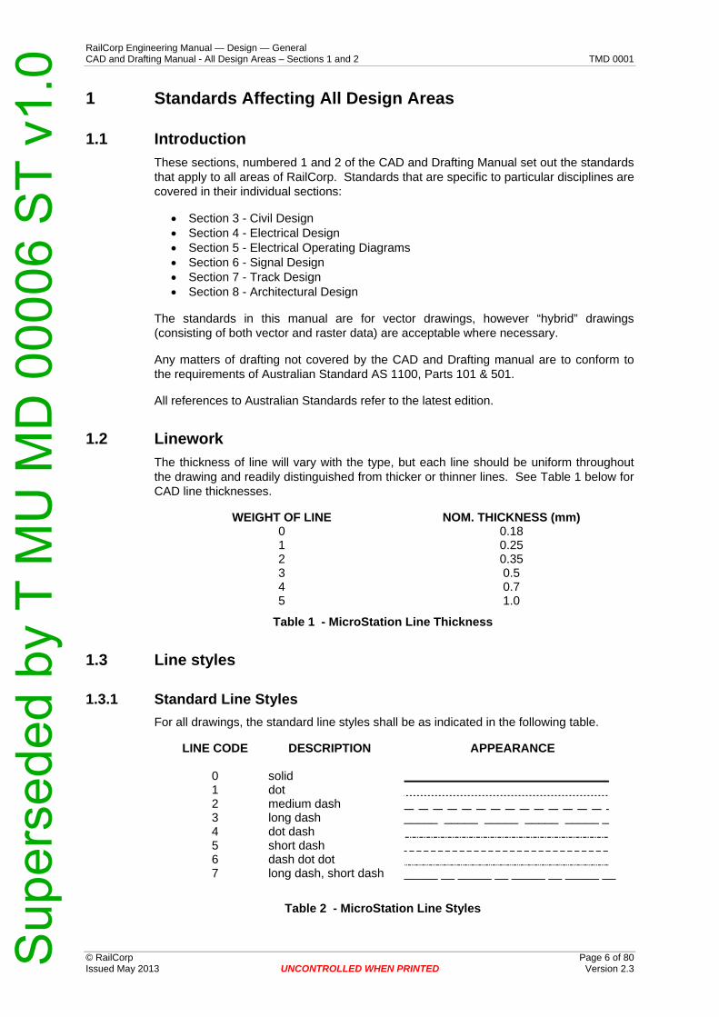
1.2 Linework
The thickness of line will vary with the type, but each line should be uniform throughout the drawing and readily distinguished from thicker or thinner lines. See Table 1 below for CAD line thicknesses.
WEIGHT OF LINE NOM. THICKNESS (mm) 0 0.18 1 0.25 2 0.35 3 0.5 4 0.7 5 1.0
Table 1 - MicroStation Line Thickness
1.3 Line styles
1.3.1 Standard Line Styles
For all drawings, the standard line styles shall be as indicated in the following table.
LINE CODE DESCRIPTION APPEARANCE
0 solid 1 dot 2 medium dash 3 long dash _____ _____ _____ _____ _____ _ 4 dot dash 5 short dash 6 dash dot dot 7 long dash, short dash _____ __ _____ __ _____ __ _____ __
Table 2 - MicroStation Line Styles
Sup
erse
ded
by T
MU
MD
000
06 S
T v1
.0

RailCorp Engineering Manual — Design — General CAD and Drafting Manual - All Design Areas – Sections 1 and 2 TMD 0001
1.3.2 Custom Line Styles
The following Custom Line Styles may be utilised by all disciplines. There are additional Custom Line Styles that are specific to particular disciplines and are specified within the particular discipline’s standards documentation.
Figure 1 - Custom Line Styles (continued next page)
© RailCorp Page 7 of 80 Issued May 2013 UNCONTROLLED WHEN PRINTED Version 2.3
Sup
erse
ded
by T
MU
MD
000
06 S
T v1
.0

RailCorp Engineering Manual — Design — General CAD and Drafting Manual - All Design Areas – Sections 1 and 2 TMD 0001
Figure 2 - Custom Line Styles (continued from previous page)
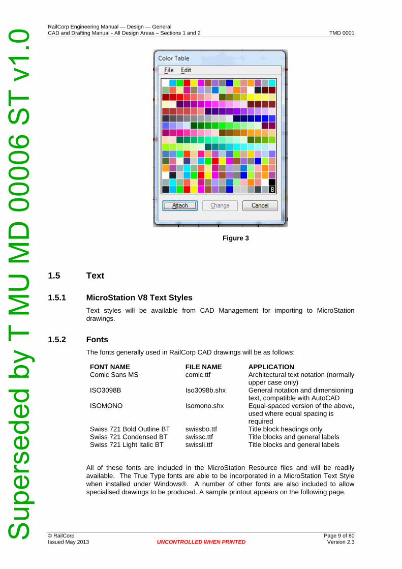
1.4 Colour
Screen colours to be used for various elements are from the RailCorp MicroStation Colour Table “RCSTcolor.tbl”, which will normally be already attached to the standard seed files listed in Section 1.8.
Level Symbology colour overrides and “ByLevel” colours are set out in Appendix B, or in the discipline-specific sections of this manual.
© RailCorp Page 8 of 80 Issued May 2013 UNCONTROLLED WHEN PRINTED Version 2.3
Sup
erse
ded
by T
MU
MD
000
06 S
T v1
.0
RailCorp Engineering Manual — Design — General CAD and Drafting Manual - All Design Areas – Sections 1 and 2 TMD 0001
Figure 3
1.5 Text
1.5.1 MicroStation V8 Text Styles
Text styles will be available from CAD Management for importing to MicroStation drawings.
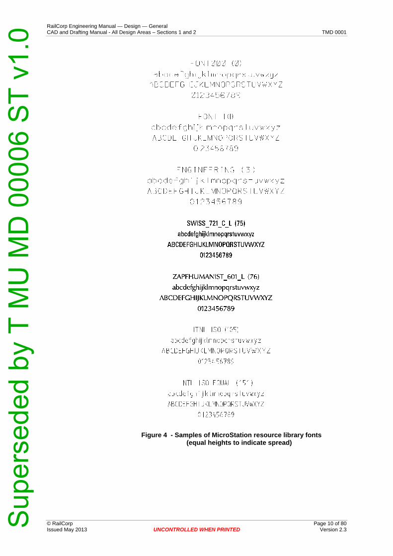
1.5.2 Fonts
The fonts generally used in RailCorp CAD drawings will be as follows:
FONT NAME FILE NAME APPLICATION Comic Sans MS comic.ttf Architectural text notation (normally
upper case only) ISO3098B Iso3098b.shx General notation and dimensioning
text, compatible with AutoCAD ISOMONO Isomono.shx Equal-spaced version of the above,
used where equal spacing is required
Swiss 721 Bold Outline BT swissbo.ttf Title block headings only Swiss 721 Condensed BT swissc.ttf Title blocks and general labels Swiss 721 Light Italic BT swissli.ttf Title blocks and general labels
All of these fonts are included in the MicroStation Resource files and will be readily available. The True Type fonts are able to be incorporated in a MicroStation Text Style when installed under Windows®. A number of other fonts are also included to allow specialised drawings to be produced. A sample printout appears on the following page.
© RailCorp Page 9 of 80 Issued May 2013 UNCONTROLLED WHEN PRINTED Version 2.3
Sup
erse
ded
by T
MU
MD
000
06 S
T v1
.0
RailCorp Engineering Manual — Design — General CAD and Drafting Manual - All Design Areas – Sections 1 and 2 TMD 0001
Figure 4 - Samples of MicroStation resource library fonts (equal heights to indicate spread)
© RailCorp Page 10 of 80 Issued May 2013 UNCONTROLLED WHEN PRINTED Version 2.3
Sup
erse
ded
by T
MU
MD
000
06 S
T v1
.0

RailCorp Engineering Manual — Design — General CAD and Drafting Manual - All Design Areas – Sections 1 and 2 TMD 0001
Figure 5 - Samples of Standard Fonts (equal heights to indicate spread) Continued
1.5.3 Height and Line Weight of Text
The height of the characters, related to the size of the drawing sheet used, shall be according to AS1100.101 (Section 4.1.2, Table 4.1), as indicated in Table 3. With some products, text must be placed in design models (as opposed to annotating the sheet model, the preferred option to be used wherever practicable). In this case, the text height as placed will be chosen to print with the correct height, taking into account the scale to be applied.
The line weight of text will be 0 for TrueType fonts and the Fill attribute for text must be checked ON for printing.
CHARACTER USE SHEET SIZE A1 A2 A3 & A4 Title block - location 7 7 5 Titles, headings, view & section designation, drawing numbers, version/amendment nos.
5 5 5
General notes, major dimensions, etc. 3.5 3.5 3.5 Minor labels & notes, amendments, general dimensions
2.5 2.5 2.5
Note: 2.5mm text can be used when space is limited, especially with notes.
© RailCorp Page 11 of 80 Issued May 2013 UNCONTROLLED WHEN PRINTED Version 2.3
Sup
erse
ded
by T
MU
MD
000
06 S
T v1
.0

RailCorp Engineering Manual — Design — General CAD and Drafting Manual - All Design Areas – Sections 1 and 2 TMD 0001
© RailCorp Page 12 of 80 Issued May 2013 UNCONTROLLED WHEN PRINTED Version 2.3
Table 3 - Height Of Text Characters (mm)
1.6 Cell Libraries for General Application
For a full listing of cell libraries for use in drawings produced by or for RailCorp in general, see Appendix A - For internal use, these files are located on the network at: M:\Rail\ustn_wsV8i\RC_Site\cell.
In addition, each discipline has its own discipline-specific set of cell libraries. See the appropriate section of this manual for details.
1.7 Levels, Level Symbology Overrides and Symbology ByLevel
All level usage and symbology for general use shall be in accordance with this manual See Appendix C - CADD Level Structure).
As with Cell Libraries, each discipline has its own discipline-specific Level Structure and Symbology standards. See the appropriate section of this manual for details.
Different levels shall be used to indicate and separate various features.
1.8 Seed Files
Seed files are used to establish working units and drawing sheets for new drawing files. The following seed files are to be used as appropriate:
model2DseedV8.dgn 2D design model (no sheet model)
model2Dsheet2DseedV8.dgn 2D design model/2D sheet model
model3DseedV8.dgn 3D design model (no sheet model)
model3Dsheet2DseedV8.dgn 3D design model/2D sheet model
For internal use, these files are found at: M:\Rail\ustn_wsV8i\RC_Site\seed
1.9 Design File Structure
MicroStation design files can be thought of as containers that house internal design models holding design data outputs.
With RailCorp moving towards a digital plan room system and tracking of file issues limitations, it has been decided to limit the number of internal models contained within the design files.
The Design files can be broken into 2 types of files:
Drawing Files (*.dgn); and Model Files (*.dgm)
1.9.1 Drawing Files
MicroStation Drawing files can be defined as design files that contain the Drawing Sheet and Title block information used to produce the published drawing (plan) for lodgement in the plan room.
Drawing files will contain one (1) internal Sheet model and one (1) internal Design model.
Sup
erse
ded
by T
MU
MD
000
06 S
T v1
.0

RailCorp Engineering Manual — Design — General CAD and Drafting Manual - All Design Areas – Sections 1 and 2 TMD 0001
© RailCorp Page 13 of 80 Issued May 2013 UNCONTROLLED WHEN PRINTED Version 2.3
The Design model within the drawing file will contain the design data, usually geo-referenced data. The Design model can also contain multiple referenced DGN model (see below) data that is required to build composite models in some cases.
The Design model will be referenced into the drawing sheet within the sheet model of the CAD design file at the appropriate scale(s) for publication.
The Sheet model will display a referenced standard size drawing sheet plotted at 1:1, the title block information and the design data referenced from the design model as indicated above.
1.9.2 DGM Model Files
MicroStation DGN Model files can be defined as design files that DON’T contain Drawing Sheet and Title block information. These files are usually files that contain design model data that is referenced by multiple drawing sheets to form the base of design (eg. Track Alignments, Overhead Wiring, Detail Survey, etc).
DGM Model files will contain a maximum of one (1) internal Design model only and NO internal Sheet models.
1.10 Drawings All drawings shall be produced with computer aided drafting (CAD) using MicroStation V8i software, with Design History initialised. Where this is not possible, contact XXXX to see if the system is compatible.
Completed and approved drawings shall show sufficient details to meet the drawings’ purpose and satisfy the clients’ requirements.
Drawings shall be read in conjunction with the specification, if any and where conflict occurs between the two, the drawings shall take precedence unless the specification expressly states otherwise.
1.11 Drawing Standards
1.11.1 Drawing Sheets
All drawings and document sheet sizes are to be in accordance with AS 1100, as shown in Table 4. The general preference for drawing sheet size is A1.
Standard Designation Cut Sheet and Drawing Sheet Dimensions (mm)
A0 1189 x 841 A1 841 x 594 A2 594 x 420 A3 420 x 297 A4 297 x 210
Table 4 - Dimensions Of Standard Drawing Sheets
1.11.2 Title Blocks
Setting out and filling in of the title block, signature block, amendment block and, if any, client title block shall be in accordance with the sample shown in Figure 6 and Figure 7.
Sup
erse
ded
by T
MU
MD
000
06 S
T v1
.0

RailCorp Engineering Manual — Design — General CAD and Drafting Manual - All Design Areas – Sections 1 and 2 TMD 0001
Figure 6 - Title Block for Internal Use (Vertical configuration)
© RailCorp Page 14 of 80 Issued May 2013 UNCONTROLLED WHEN PRINTED Version 2.3
Sup
erse
ded
by T
MU
MD
000
06 S
T v1
.0

RailCorp Engineering Manual — Design — General CAD and Drafting Manual - All Design Areas – Sections 1 and 2 TMD 0001
Figure 7 - Title Block for Internal Use (Horizontal configuration)
© RailCorp Page 15 of 80 Issued May 2013 UNCONTROLLED WHEN PRINTED Version 2.3
Sup
erse
ded
by T
MU
MD
000
06 S
T v1
.0

RailCorp Engineering Manual — Design — General CAD and Drafting Manual - All Design Areas – Sections 1 and 2 TMD 0001
For external contractors, a blank title block and a RailCorp disclaimer note are included on the standard drawing sheet as depicted in Figure 8 and Figure 9.
Figure 8 - Title Block for External Use (Vertical configuration)
© RailCorp Page 16 of 80 Issued May 2013 UNCONTROLLED WHEN PRINTED Version 2.3
Sup
erse
ded
by T
MU
MD
000
06 S
T v1
.0

RailCorp Engineering Manual — Design — General CAD and Drafting Manual - All Design Areas – Sections 1 and 2 TMD 0001
Figure 9 - Title Block for External Use (Horizontal configuration)
© RailCorp Page 17 of 80 Issued May 2013 UNCONTROLLED WHEN PRINTED Version 2.3
Sup
erse
ded
by T
MU
MD
000
06 S
T v1
.0

RailCorp Engineering Manual — Design — General CAD and Drafting Manual - All Design Areas – Sections 1 and 2 TMD 0001
© RailCorp Page 18 of 80 Issued May 2013 UNCONTROLLED WHEN PRINTED Version 2.3
The signatories’ box shall contain the printed surnames with initials of the persons who had performed the design and drawing tasks. For designs identified as critical by a particular discipline Chief Engineer, the signatories’ box shall also contain the electronic or wet signatures of the persons who had performed the design and drawing tasks. The relevant Chief Engineer shall advise the design personnel that their electronic or wet signatures would be required on drawings at the time of granting Engineering Authority for design.
NOTE:
A wet signature is an original signature written by hand in ink on paper i.e. the original document is required.
An electronic signature is the electronic equivalent of a handwritten signature, where a person adopts the contents of an electronic message through any electronic means. An electronic signature creates an audit history that includes verification of who sent the signed document and to whom and a date and time stamp of when i.e. a non-repudiation process. Example: It is an electronic signature that you apply after you swipe your credit or debit card at a retailer. But it might also be done by checking a box on a computer, be typed or applied with a mouse or touchpad.
A digital signature is a kind of electronic signature that includes all of the above, plus the addition of a certificate of authority issued by a third party that validates the identity of the signer and the signature. The application of a digital signature includes PKI (public key infrastructure) encryption technology.
1.11.3 Tags
Drawing sheets are attached to the drawings as cells and now contain title blocks supporting the attribute exchange feature of ProjectWise that link tags in MicroStation documents with ProjectWise properties.
For internal users working in the integrated MicroStation environment, the title block tags are automatically populated with the information entered during document creation in ProjectWise.
External users of MicroStation are required to use the MicroStation EDIT TAGS command and pick the right bottom corner of the drawing sheet frame (see Figure 10) with the Constructions view attribute turned on. The list of attached tag sets available for editing is shown in Figure 11
To enter the title block information choose the TitleBlock tag set (Figure 12). To edit the Accepted by RailCoprp box information choose the EX_AT tag set (Figure 13). The third tag set EX_PR is invisible information required by the plan room (Figure 14).
Drawing identifier along border of drawing sheets for external use has been incorporated. In AutoCAD this information is updated automatically at the time of print. In MicroStation to update this information, the Drawing_Indentifier.tbl must be attached at the time of plot.
Sup
erse
ded
by T
MU
MD
000
06 S
T v1
.0

RailCorp Engineering Manual — Design — General CAD and Drafting Manual - All Design Areas – Sections 1 and 2 TMD 0001
Figure 10 – Pick this corner to edit Tag Sets in MicroStation
Figure 11 – Edit Tags dialog box in MicroStation
© RailCorp Page 19 of 80 Issued May 2013 UNCONTROLLED WHEN PRINTED Version 2.3
Sup
erse
ded
by T
MU
MD
000
06 S
T v1
.0

RailCorp Engineering Manual — Design — General CAD and Drafting Manual - All Design Areas – Sections 1 and 2 TMD 0001
Figure 12 – Edit Tags [TitleBlock] dialog box in MicroStation
Figure 13 – Edit Tags dialog box [EX_AT] in MicroStation
© RailCorp Page 20 of 80 Issued May 2013 UNCONTROLLED WHEN PRINTED Version 2.3
Sup
erse
ded
by T
MU
MD
000
06 S
T v1
.0

RailCorp Engineering Manual — Design — General CAD and Drafting Manual - All Design Areas – Sections 1 and 2 TMD 0001
Figure 14 – Edit Tags [EX_PR] dialog box in MicroStation
External users of AutoCAD are required to use the AutoCAD EATTEDIT command to edit the attributes attached to the Titleblock, EX-AT and EX-PR blocks. Invoking EATTEDIT command or double clicking any of the tags displays a dialog box as shown in Figure 15. To edit the EX-AT attributes, double-click the tbAcceptorsTitle tag. The EX-PR block contains invisible information required by the plan room. To edit these attributes invoke the EATTEDIT command and pick the left bottom corner of the drawing sheet frame (see Figure 16). This will display a dialog box as shown in Figure 17.
The tbFileNo tag in the FILE No field on external drawing sheets should be the name of the company’s or contractor’s project calculations file.
© RailCorp Page 21 of 80 Issued May 2013 UNCONTROLLED WHEN PRINTED Version 2.3
Sup
erse
ded
by T
MU
MD
000
06 S
T v1
.0

RailCorp Engineering Manual — Design — General CAD and Drafting Manual - All Design Areas – Sections 1 and 2 TMD 0001
Figure 15 – Enhanced Attribute Editor (Titleblock) dialog box in AutoCAD
© RailCorp Page 22 of 80 Issued May 2013 UNCONTROLLED WHEN PRINTED Version 2.3
Sup
erse
ded
by T
MU
MD
000
06 S
T v1
.0

RailCorp Engineering Manual — Design — General CAD and Drafting Manual - All Design Areas – Sections 1 and 2 TMD 0001
Figure 16 – Pick this corner to edit EX_PR attributes in AutoCAD
Figure 17 – Enhanced Attribute Editor (EX_PR) dialog box in AutoCAD
Figure 18 shows Design Change Amendment Box. The Design Change Amendment Box is used on drawings amended to show post-AFC (Approved for Construction) design changes. A design change is a change to the original design intent or configuration which warrants design review and acceptance by RailCorp. The design organisation designer determines if a post-AFC change is a design change. Any change that can affect a safety critical item, or where required by discipline requirements shall be referred to the design organisation designer.
Designs changed during post-AFC stage shall undergo the normal design acceptance process and shall have design acceptance by the Chief Engineer or delegate before construction. Unless the design changes are shown on a new drawing, the design change amendment box is required. Design changes shall be signed off on drawings by the designer, design checker, approver and acceptance authority, all with appropriate engineering authority.
© RailCorp Page 23 of 80 Issued May 2013 UNCONTROLLED WHEN PRINTED Version 2.3
Sup
erse
ded
by T
MU
MD
000
06 S
T v1
.0

RailCorp Engineering Manual — Design — General CAD and Drafting Manual - All Design Areas – Sections 1 and 2 TMD 0001
NOTE: A non-design change is a change to the original design that does not impact on the design intent or configuration and which does not warrant design review and acceptance by RailCorp. Such changes shall be documented in 'as-built' changes and the normal amendment box is used.
On drawings that Design Change Amendment Box is required, the layer R-DSHT-AMND should be turned off to hide the standard Amendment Box.
Figure 18 – Design Change Amendment Box
External drawing sheets have also Multi-Designer Signature Box (see Figure 19) for identifying of multiple designers and disciplines. This block can be deleted from the drawing if unused.
The Multi-Designer Signature Box shall contain the printed surnames with initials of the persons who had performed the design and drawing tasks
There are dedicated boxes on the title block for entry of the following numbers:
Drawing Number (EDMS Number) is obtained from the Plan Room File Number is the TRIM (RailCorp Filing System) Number of the main job file.
Figure 19 – Multi-Designer Signature box
© RailCorp Page 24 of 80 Issued May 2013 UNCONTROLLED WHEN PRINTED Version 2.3
Sup
erse
ded
by T
MU
MD
000
06 S
T v1
.0

RailCorp Engineering Manual — Design — General CAD and Drafting Manual - All Design Areas – Sections 1 and 2 TMD 0001
© RailCorp Page 25 of 80 Issued May 2013 UNCONTROLLED WHEN PRINTED Version 2.3
For CAD file naming conventions see Appendix C - CAD File Naming Conventions.
Drawing Version - All drawings for review or checking purposes shall be assigned a numerical version i.e. version 1, 2, 3 etc. Description of each review version may be included in the amendment box above the title box – for QA purposes. When drawings are finalised i.e. ready for issue either as a “Reference Design” or "Approved For Construction" design, whichever the case may be, the version shall be changed to A when registering in the Plan Room. All subsequent amendment versions accepted for issue shall be B, C, D etc. A short description of each amendment shall be included above the drawing title block. A new EDMS number shall be used for all drawings that are intended for Approved For Construction drawings, even if the drawing is a copy of a Reference Design drawing.
Sup
erse
ded
by T
MU
MD
000
06 S
T v1
.0

RailCorp Engineering Manual — Design — General CAD and Drafting Manual - All Design Areas – Sections 1 and 2 TMD 0001
© RailCorp Page 26 of 80 Issued May 2013 UNCONTROLLED WHEN PRINTED Version 2.3
1.11.4 Coordination Between Sections
Drawings prepared by other disciplines are commonly used as references on drawings issued by any RailCorp area.
Coordination between drafters from different disciplines is necessary to ensure that, where possible, drawings for the particular project have matching orientation, scales, working units, limits and drawing sheet sizes.
The Global Origins and coordinate systems will also be critically important where “real world” coordinates are being used.
1.11.5 Orientation
The drafter should produce a drawing which is set out in accordance with the rules of orientation explained below. However, if these rules are likely to cause confusion with other drawings, the clarity of the drawing should not be compromised.
Whenever it is necessary to depart from the rules of orientation, the system adopted should be clearly noted. Regardless of the system used, the orientation of all views on the drawing should be consistent with that of any key view.
General Rules for Orientation:
Site plans and locality maps should be oriented with north or assumed north to the top of the sheet. If this orientation is not convenient, then the north should be towards the left side of the sheet. In special cases, where coordination between disciplines is required, north will be in the direction agreed among the disciplines.
On plans and maps a standard north point arrow shall be used and, where required, sufficient grid lines of the relevant grid system should be shown to accurately locate the area covered by the drawing. The standard north point arrow is located in the standard cell library. The arrow is marked “North”, “N” or “assumed North” as applicable and placed in the upper left corner of the plan.
Plan views, layout drawings, elevations and sections should be drawn with the track appearing horizontal on the sheet and Sydney on the left, where practicable. However, plans for overbridges should be drawn with the track vertical and Sydney at the bottom. The Sydney end of an underbridge is to be labelled “From Sydney,” the other end “To …....” (the next main railway station after the bridge site). It may be necessary in some cases (eg views of retaining walls on the up side of the track) to orientate the drawings with Sydney on the right, in which case it must be clearly labelled. Cross-sections perpendicular to the track through bridges etc should be shown as viewed from the Sydney side (ie facing country, towards increasing kilometrage).
1.11.6 Coordinates & Bearings
When a point on a drawing is located by reference to the grid system, the coordinates should be written correct to three decimal places of a metre, as in the following example. Coordinates shall be written in accordance with the grid system adopted and the grid system shall be identified on the drawing.
E 363 241.271
N 1 240 401.750
The bearing of a line, when required, should be given as degrees, minutes and seconds of arc east of grid North.
Sup
erse
ded
by T
MU
MD
000
06 S
T v1
.0

RailCorp Engineering Manual — Design — General CAD and Drafting Manual - All Design Areas – Sections 1 and 2 TMD 0001
1.11.7 Track Kilometrages
Kilometrages are measured from Sydney along the centreline of the track and written in the form: 54.321km. If used for set out purposes, the kilometrage is taken to the nearest millimetre and written in the form: 54.321 789km. Views are normally oriented with Sydney on the left, so track kilometrages normally increase from left to right across a drawing.
1.11.8 Layout
An engineering drawing is intended to show clearly and without ambiguity the feature being detailed. A good layout is the first essential step to achieving this.
Hidden lines should not be shown on a layout unless they give details which are not readily apparent on other views. In most cases it is preferred to show interior details by an additional section rather than by showing hidden lines.
1.11.9 Headings
All headings shall be underlined eg PLAN; ELEVATION; MS12+395. Headings for sections and details shall include an 18mm dia circle enclosing the identifying letter or number and, where applicable, a reference drawing number. The scale for sections and details shall be indicated underneath the heading. All these aspects of headings are illustrated in Figure 20 below.
Figure 20 - Heading for Sections or Details
1.11.10 Sections
Standard section arrows, located in the cell library Rc_DraftingDetails_v8.cel, (see Figure 21) shall be used to clearly indicate the location of the cutting plane. For internal RailCorp use, this library is located at:
M:\Rail\ustn_wsV8i\RC_Site\cell\Rc_DraftingDetails_v8.cel.
Usually one set of arrows is sufficient for each section, but in some cases a repetition on other views may be necessary.
A section shall be identified by a letter placed inside a circle. The orientation should be consistent with the rules of projection. The sections should be placed as near as possible to the view from where they are cut. They shall be drawn to the same or larger scale than the original view, using true projection. The letters I, O and Q are not to be used as section letters.
Where a section is drawn on a different sheet to that of the original view, then the last 3 digits of the section sheet’s drawing number shall be shown in the lower half of the section circle on the original view. Likewise the actual section heading shall include a reference to the original sheet from where the section was taken, as shown in the
© RailCorp Page 27 of 80 Issued May 2013 UNCONTROLLED WHEN PRINTED Version 2.3
Sup
erse
ded
by T
MU
MD
000
06 S
T v1
.0

RailCorp Engineering Manual — Design — General CAD and Drafting Manual - All Design Areas – Sections 1 and 2 TMD 0001
example in Figure 20 above.. If the section is on the same sheet as the original view then a dash "-" shall be placed in the lower half of the section circle.
1.11.11 Details
Where it is necessary to identify particular areas not covered by a section, it can be done so with a detail. Details shall be identified by a number. An arrow can be placed as the detail pointer if the item being detailed is small; however, it is preferable that a circle or an ellipse (solid line and size to suit) be placed around the area to be detailed (see Figure 21 below. The detail reference number is to follow the same rules set out for sections.
Figure 21 - Sectioning and Detail Symbols
1.11.12 Materials Symbology
Where it is necessary to identify materials by symbols such as fill patterns, the symbols shall be chosen from the “Rc_AreaPattern_v8” cell library. For internal RailCorp use, this library is located at “M:\Rail\ustn_wsV8i\RC_Site\cell”
Stippling (used for concrete) shall not be used in sections that contain reinforcement. Stippling or light shading may be used in moderation for plain concrete areas.
1.11.13 Scales Of Drawings
Scales to be used for drawings will vary with the size and character of the feature, and with the degree of detail to be shown.
All views should be drawn to scale if possible. Distorted scales should be used only in special cases, where the required detail cannot be shown effectively on an undistorted scale. Scales should be indicated under each heading on the drawing. Views not drawn to scale are to be noted “NTS”.
© RailCorp Page 28 of 80 Issued May 2013 UNCONTROLLED WHEN PRINTED Version 2.3
5:1 4:1 2:1 10:1Full size & enlargement ratios
1.1
Reduction ratios
1:2 1:20 1:200
1:2.5 1:25 1:250
1:5 1:50 1:500
1:10 1:100 1:1000
Sup
erse
ded
by T
MU
MD
000
06 S
T v1
.0

RailCorp Engineering Manual — Design — General CAD and Drafting Manual - All Design Areas – Sections 1 and 2 TMD 0001
© RailCorp Page 29 of 80 Issued May 2013 UNCONTROLLED WHEN PRINTED Version 2.3
1:2 000 1:2 500 1:25 000
1:5 000 1:50 000
1:10 000 1:100 000
Table 5 - Engineering Drawing Scales
Where different scales are used for horizontal and vertical dimensions, such as Transmission line, OHW & Bridge profiles, each scale shall be clearly indicated on the drawing sheet.
e.g. HORIZONTAL SCALE 1:500 VERTICAL SCALE 1:100
The number of different scales used on any one drawing shall be kept to a minimum. Scales shall be large enough to permit clear interpretation of the information and ensure clarity of prints on reduced copies, especially A4 copies of A1 originals.
All drawing sheets shall include a scale bar cell representing the overall scale of the drawing, the cell shall be chosen from the “Rc_BarScales_v8” cell library.
For internal RailCorp use, this library is located at “M:\Rail\ustn_wsV8i\RC_Site\cell”
1.12 Dimensioning
Pre-defined MicroStation V8 dimension styles will normally be used. These may be imported from appropriate “dgnlib” files, which are available for each discipline. See the appropriate discipline’s section for details.
1.12.1 General
Each dimension necessary for the complete definition of a particular feature should be given on the drawing and should appear only once. It should not be necessary for the drawing to be scaled. All dimensions for a particular feature should be shown on a single view where possible.
1.12.2 Dimension Lines
All dimension and extension lines should be thin, normally MicroStation line weight 0, nominal thickness 0.18mm on printout.
Extension lines should extend half of the text height beyond the dimension line and start the same distance clear of the outline of the feature. Extension lines should extend half of the text height past intersection points (IPs) and points on surfaces.
Dimension lines wherever practicable should be placed outside the outline of the object. Dimensions should be placed above the dimension line, not below or interrupting the dimension line. Dimension lines should terminate with easily readable standard filled arrowheads, normally 1.0 to 1.5 text heights long and 0.5 text heights wide. An exception to this is where the application calls for a stroke or dot. In these cases, the standards are defined for the particular discipline.
A centreline or a line which is an extension of a centreline, or a part of an outline, should not be used as a dimension line. Figure 21 below illustrates these characteristics of extension lines and dimension lines.
Sup
erse
ded
by T
MU
MD
000
06 S
T v1
.0

RailCorp Engineering Manual — Design — General CAD and Drafting Manual - All Design Areas – Sections 1 and 2 TMD 0001
Figure 22 - Dimension Lines
If the overall dimension of a chain of dimensions is a critical value then one of the dimensions in the chain should be omitted, as shown in Figure 22 below. Stacked dimension lines should be spaced at 10mm intervals.
Figure 23 - Dimension Chain
Leaders for notes etc should terminate in arrowheads or filled circles and should originate at either the beginning or end of a note (not above or below). Arrowheads should always terminate on a line, dots should be within the outline of the object. See Figure 23 below.
Leaders should be as near as possible to perpendicular to other lines which they touch or cross. See Figure 24. They should not be parallel to adjacent dimension or projection lines. The use of long leaders should be avoided.
© RailCorp Page 30 of 80 Issued May 2013 UNCONTROLLED WHEN PRINTED Version 2.3
Sup
erse
ded
by T
MU
MD
000
06 S
T v1
.0

RailCorp Engineering Manual — Design — General CAD and Drafting Manual - All Design Areas – Sections 1 and 2 TMD 0001
Figure 24 - Typical Leaders
Figure 25 - Leaders Touching Other Lines
1.12.3 Dimension Text
Dimensions should be placed so that they may be read either from the bottom of the drawing (for horizontal text) or the right-hand side of the drawing (for vertical text).
Where it is necessary to indicate that a particular dimension is not to scale, the abbreviation NTS should be added.
Radii should be dimensioned by a dimension line which passes through, or is in line with, the centre of the arc. The dimension line should have one arrowhead only and the abbreviation ‘R’ should always lead the dimension.
1.13 Gradients & Batters
“Slope” is a general term of indefinite meaning and should not be used. The term “gradient” is used for features with gradual slopes such as tracks, roadways and tunnels, while the term “batter” is used for steeper slopes such as excavations and faces of walls. (In the case of gradients for drainage systems the term “fall” is used).
1.13.1 Gradients
Gradients may be expressed as a percentage. A gradient of 5.0% indicates a displacement of 5 units vertically in 100 units horizontally.
© RailCorp Page 31 of 80 Issued May 2013 UNCONTROLLED WHEN PRINTED Version 2.3
Sup
erse
ded
by T
MU
MD
000
06 S
T v1
.0

RailCorp Engineering Manual — Design — General CAD and Drafting Manual - All Design Areas – Sections 1 and 2 TMD 0001
Gradients may also be expressed as a unit vertical displacement in a horizontal distance, such as “1 in 20”. The first figure should always be the vertical dimension.
In plan views, and where a gradient is given for a surface which is close to horizontal, such as 1 in 100, an arrow should indicate the direction of fall. Alternatively, a small right angled triangle may be used to show gradual gradients or crossfalls, with the two sides including the right angle dimensioned, one being unity. See Figure 25 below.
Figure 26 - Indicating Gradients
1.13.2 Batters
Batters should be expressed as a horizontal displacement relative to a vertical distance, one of these dimensions being given as unity eg “2 to 1”, or “0.7 to 1”. The first figure should always be the horizontal dimension. A small right angled triangle may be drawn and dimensioned to indicate batters. See Figure 26 below.
Figure 27 - Indicating Batters
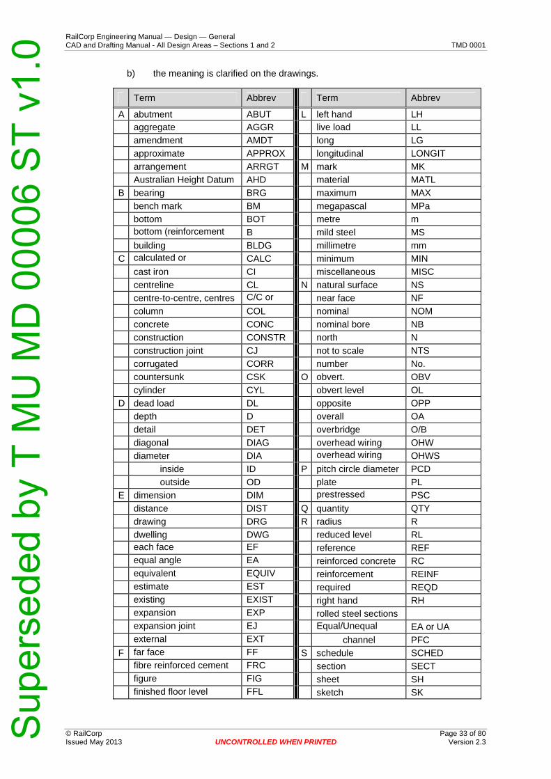
1.14 Abbreviations
All abbreviations shall be in accordance with AS 1100, Part 101. Abbreviations shall be in upper case letters.
1.14.1 Common Abbreviations
Table 6 on the following pages gives abbreviations commonly used on RailCorp drawings. This list is not exhaustive. Other abbreviations, and other meanings for abbreviations listed in the table, may be used provided:
a) their common usage in particular fields is clear, or
© RailCorp Page 32 of 80 Issued May 2013 UNCONTROLLED WHEN PRINTED Version 2.3
Sup
erse
ded
by T
MU
MD
000
06 S
T v1
.0
RailCorp Engineering Manual — Design — General CAD and Drafting Manual - All Design Areas – Sections 1 and 2 TMD 0001
© RailCorp Page 33 of 80 Issued May 2013 UNCONTROLLED WHEN PRINTED Version 2.3
b) the meaning is clarified on the drawings.
Term Abbrev Term Abbrev
A abutment ABUT L left hand LH aggregate AGGR live load LL
amendment AMDT long LG
approximate APPROX longitudinal LONGIT
arrangement ARRGT M mark MK
Australian Height Datum AHD material MATL
B bearing BRG maximum MAX
bench mark BM megapascal MPa
bottom BOT metre m
bottom (reinforcement B mild steel MS
building BLDG millimetre mm
C calculated or CALC minimum MIN
cast iron CI miscellaneous MISC
centreline CL N natural surface NS
centre-to-centre, centres C/C or near face NF
column COL nominal NOM
concrete CONC nominal bore NB
construction CONSTR north N
construction joint CJ not to scale NTS
corrugated CORR number No.
countersunk CSK O obvert. OBV
cylinder CYL obvert level OL
D dead load DL opposite OPP
depth D overall OA
detail DET overbridge O/B
diagonal DIAG overhead wiring OHW
diameter DIA overhead wiring OHWS
inside ID P pitch circle diameter PCD
outside OD plate PL
E dimension DIM prestressed PSC
distance DIST Q quantity QTY
drawing DRG R radius R
dwelling DWG reduced level RL
each face EF reference REF
equal angle EA reinforced concrete RC
equivalent EQUIV reinforcement REINF
estimate EST required REQD
existing EXIST right hand RH
expansion EXP rolled steel sections
expansion joint EJ Equal/Unequal EA or UA
external EXT channel PFC
F far face FF S schedule SCHED
fibre reinforced cement FRC section SECT
figure FIG sheet SH
finished floor level FFL sketch SK
Sup
erse
ded
by T
MU
MD
000
06 S
T v1
.0

RailCorp Engineering Manual — Design — General CAD and Drafting Manual - All Design Areas – Sections 1 and 2 TMD 0001
© RailCorp Page 34 of 80 Issued May 2013 UNCONTROLLED WHEN PRINTED Version 2.3
Term Abbrev Term Abbrev
finished surface level FSL setout point SOP finished pavement level FPL square SQ
flange FLG stainless steel SS
flat FL standard STD
floor FLR superelevation S or Ea
G galvanized GALV symmetry or SYM
general arrangement GA T tangent point TP
ground level GL temporary TEMP
H height HGT thick THK
hexagon HEX to be advised TBA
high track rail level HTRL tonne t
holding down HD top (for f )
T
hollow section transition point TRS
circular CHS transom top TT
rectangular RHS timber opening, TOTT
square SHS timber opening, TOBT
horizontal HORIZ typical TYP
I include, including, INCL U ultimate tensile UTS
internal INT underbridge U/B
inside or internal ID unequal angle UA
Integrated Survey Grid ISG universal beam UB
international system of units (Systeme International d’unites)
SI universal column UC
intersection point IP unless noted UNO
invert INV V vertical VERT
invert level IL vertical curve VC
K kilogram kg volume VOL
kilometre km W water level, WL
kilopascal kPa welded beam WB
kilometre km welded column WC
kilopascal kPa
Table 6 - Common Abbreviations (End)
Explanatory Note: Abbreviations and symbols precede any numerical value. e.g. Ø36, RL 19.165, R25.
1.15 Notes, References and Locality Diagrams
1.15.1 General
The notes and references should occupy a space 140mm wide from the right hand margin above the title block for A1 sheets, and 125mm wide for A2 and A3 sheets.
Where several notes on particular subjects are required, it is more effective to group these notes under separate headings such as ‘Steelwork’, ‘Concrete’, ‘Reinforcement’ etc. Each note, under these headings, is to be numbered.
Sup
erse
ded
by T
MU
MD
000
06 S
T v1
.0

RailCorp Engineering Manual — Design — General CAD and Drafting Manual - All Design Areas – Sections 1 and 2 TMD 0001
1.15.2 Notes
© RailCorp Page 35 of 80 Issued May 2013 UNCONTROLLED WHEN PRINTED Version 2.3
Notes should generally be kept to a minimum. It is preferable for information concerning a particular feature of the drawing to appear in the body of the drawing at the point where it applies.
Where descriptions of materials or similar information are given on contract drawings, the notes should be in accordance with the appropriate specification.
For larger groups of drawings, the general arrangement may include notes which are common to all drawings of the group. The first note of the other drawings should then be a reference to the general arrangement drawing for general notes.
General Arrangement drawings should show the principal design basis, ie Design Loading, Live Loads, Wind Loads etc.
1.15.3 References
Reference drawings shall be listed below the notes. The list should include sufficient drawings to enable the construction / fabrication of the particular feature.
References listed on a particular drawing will usually include only those drawings necessary to cover that particular part of the work. The General Arrangement (or the Cover Sheet if any) should list all drawings that are relevant to the project. Drawings by other disciplines that have a direct bearing on the particular drawing (ie “associated” drawings) shall be listed.
In some instances it may be desirable to add, in the body of the drawing at the appropriate place, a reference to a drawing giving details of a particular section of the work. Such references are usually also included under the references heading, as well as in the body of the drawing. See Figure 28 below.
When there are cross references to other drawings, it is preferred that the RailCorp EDMS number is used.
For drawings prepared by an External Design Organisation (EDO), an acceptable alternative is for the EDO to use its own drawing numbers (Supplier Numbers) obtained from its own document management system provided the following requirements are met:
1. A cover sheet(s) with its own Supplier Number shall be provided containing a schedule of all drawings for the design package, complete with Drawing Title Description, Supplier Number and corresponding RailCorp EDMS number for each drawing. The revision version and date of the drawings shall also be provided.
2. Cover sheets shall also comply with requirements contained in discipline specifications or other discipline standards.
3. For all drawings in the design package, the Supplier Number shall be used consistently for cross referencing and not a mix of cross referencing using Supplier Number for some drawings and EDMS number for others, unless the cross referenced drawing is a RailCorp drawing.
4. If a drawing that is cross referenced is not part of the design package, it shall be listed on the cover sheet under "Other Referenced Drawings".
Sup
erse
ded
by T
MU
MD
000
06 S
T v1
.0
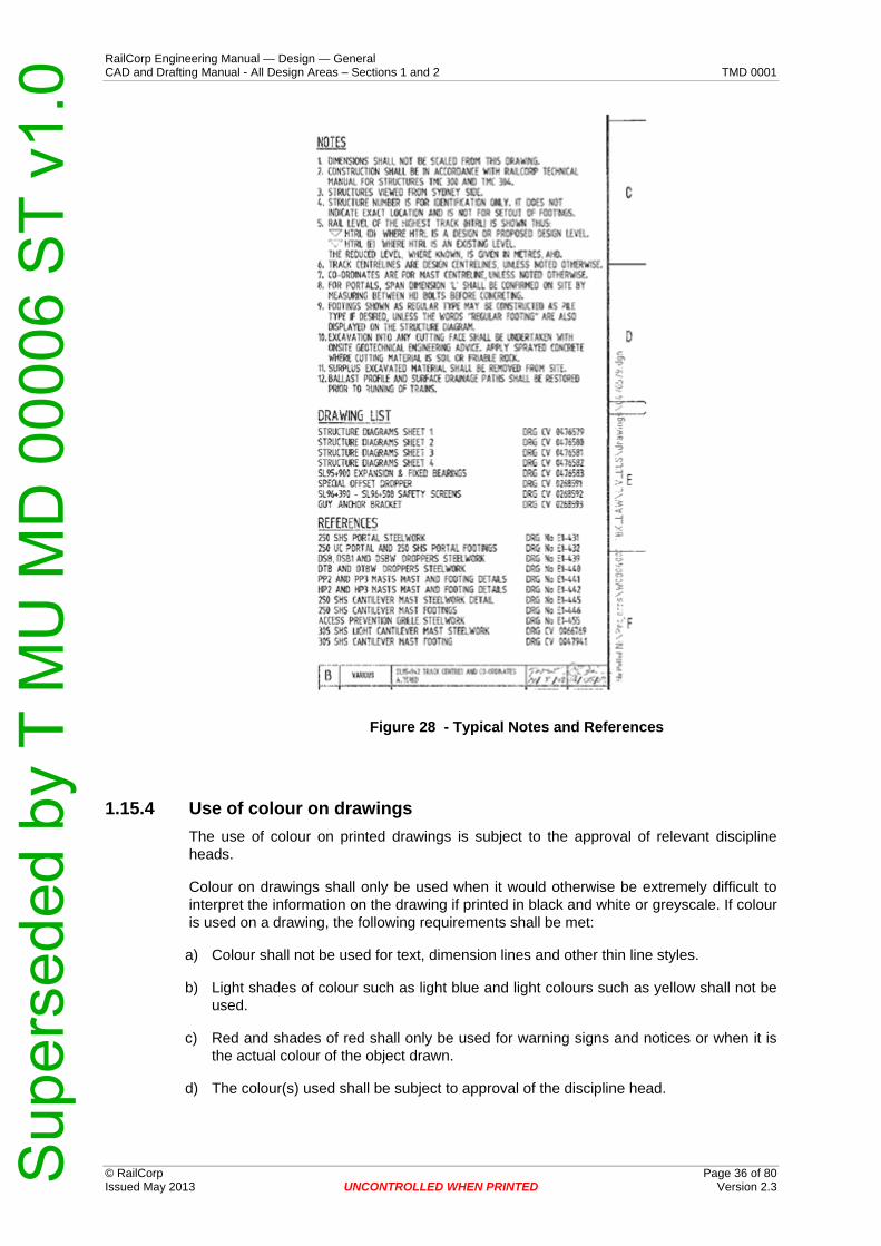
RailCorp Engineering Manual — Design — General CAD and Drafting Manual - All Design Areas – Sections 1 and 2 TMD 0001
Figure 28 - Typical Notes and References
1.15.4 Use of colour on drawings
The use of colour on printed drawings is subject to the approval of relevant discipline heads.
Colour on drawings shall only be used when it would otherwise be extremely difficult to interpret the information on the drawing if printed in black and white or greyscale. If colour is used on a drawing, the following requirements shall be met:
a) Colour shall not be used for text, dimension lines and other thin line styles.
b) Light shades of colour such as light blue and light colours such as yellow shall not be used.
c) Red and shades of red shall only be used for warning signs and notices or when it is the actual colour of the object drawn.
d) The colour(s) used shall be subject to approval of the discipline head.
© RailCorp Page 36 of 80 Issued May 2013 UNCONTROLLED WHEN PRINTED Version 2.3
Sup
erse
ded
by T
MU
MD
000
06 S
T v1
.0
RailCorp Engineering Manual — Design — General CAD and Drafting Manual - All Design Areas – Sections 1 and 2 TMD 0001
© RailCorp Page 37 of 80 Issued May 2013 UNCONTROLLED WHEN PRINTED Version 2.3
e) A box containing the following note shall be added to the drawing located near the bottom middle of the drawing:
DRAWING COLOUR CODED — PRINT ALL COPIES IN COLOUR
1.15.5 Use of Design History feature on MicroStation CAD files
MicroStation Design history allows users to better manage the design process. It provides a complete revision control system that allows users to track and view the incremental changes made to a model, (as well as changes to attached references). You can restore elements to a prior state through a combination of undoing and redoing historic changes.
Changes can be tracked down to the element level. To help track the revisions, each is identified with a revision number, file name, date and time, author, description of the change, and tags. While the revisions are attributed to a single author, the changes can be viewed and restored from a wide range of combinations.
Once a revision has been committed, there are a number of viewing and recovery options. You can:
Track all committed changes
View changes before and after
View changes on an element level
Select changes via a list filter
Undo historic changes
Redo historic changes
Restore revisions by date and number
Return to element changes within revisions
Note: This feature is not available in any version of AutoCAD. The current release of AutoCAD is 2012.
1.16 Product Specification
Where specific performance from a generic product (eg concrete) is required, the performance requirements should be stated on the drawing. If the designer wishes to identify a specific proprietary product, the product name may be specified and the words “or equivalent” added. Alternatively, for critical applications where the designer needs to have more control over the products to be used, the words “or approved equivalent” should be used. An instruction such as “product shall be installed/mixed/placed in accordance with the manufacturer’s specification” shall also be included.
2 Location Plans and Details Site Plans Location diagrams should contain sufficient information to enable the location of the work site to be easily determined.
Sup
erse
ded
by T
MU
MD
000
06 S
T v1
.0

RailCorp Engineering Manual — Design — General CAD and Drafting Manual - All Design Areas – Sections 1 and 2 TMD 0001
Location plans and detailed site plans should together contain sufficient information to enable any particular feature to be located without difficulty. A location plan and a detailed site plan are usually combined for convenience on one drawing, the general arrangement.
2.1 Location Plans
These should be on a sufficiently small scale to cover the whole of the site plus major features of the surrounding area such as roads, rivers and towns. Contour lines and other fine detail need not be shown. The site itself should be circled and labelled. North should be towards the top of the sheet. Text should be large enough to read if prints are reduced. See typical example Figure 29 below.
Figure 29 - Location Plans
2.2 Detailed Site Plans
The scale of the detailed site plan should be sufficiently large to cover the whole of the site in enough detail for easy identification of the various features. The grid system and north point arrow should be shown. Where contours are required, the recommended interval for contour lines is 2m. Levels should be given to 0.001m. In the notes, the origin of the grid system and the datum used for vertical control should be given where applicable. See typical example Figure 30 below.
© RailCorp Page 38 of 80 Issued May 2013 UNCONTROLLED WHEN PRINTED Version 2.3
Sup
erse
ded
by T
MU
MD
000
06 S
T v1
.0

RailCorp Engineering Manual — Design — General CAD and Drafting Manual - All Design Areas – Sections 1 and 2 TMD 0001
Figure 30 - Detail Site Plan
© RailCorp Page 39 of 80 Issued May 2013 UNCONTROLLED WHEN PRINTED Version 2.3
Sup
erse
ded
by T
MU
MD
000
06 S
T v1
.0

RailCorp Engineering Manual — Design — General CAD and Drafting Manual - All Design Areas – Sections 1 and 2 TMD 0001
© RailCorp Page 40 of 80 Issued May 2013 UNCONTROLLED WHEN PRINTED Version 2.3
Appendix A Cell Libraries for General Application Below is a listing of RailCorp general-use cell libraries. For internal RailCorp use, all files are located on the network at: M:\Rail\ustn_wsV8i\RC_Site\cell.
RailCAD.cel
Rc_BarScales_v8.cel
Rc_NorthPoints_v8.cel
Rc_DraftingDetails_v8.cel
Rc_DetSurvey_v8.cel
A complete listing of cells can be obtained by down loading the resource files from the RailCorp Engineering Extranet and opening the cell libraries.
Sup
erse
ded
by T
MU
MD
000
06 S
T v1
.0

RailCorp Engineering Manual — Design — General CAD and Drafting Manual - All Design Areas – Sections 1 and 2 TMD 0001
© RailCorp Page 41 of 80 Issued May 2013 UNCONTROLLED WHEN PRINTED Version 2.3
Appendix B CADD Level Structure The MicroStation V8 levels for placement of various types of elements, Level Symbology Overrides and Symbology ByLevel shall be in accordance with the table on this and the following pages, unless a discipline-specific structure is specified for a particular drawing.
1.1 Global Level Structure
1.1.1 Levels that are generic to all of Design within the RailCAD System
Nam
e
Num
ber
Des
crip
tion
Ove
rrid
eCol
or
Ove
rrid
eSty
le
Ove
rrid
eWei
ght
ByL
evel
Col
or
ByL
evel
Styl
e
ByL
evel
Wei
ght
Glo
balD
ispl
ay
Elem
entA
cces
s
Plot
R-DSHT-LINE-TRIM 1 Drawing Sheet: Trim Linework 251 0 0 0 0 0 1 0 1 R-DSHT-LINE-FRME 2 Drawing Sheet: Frame Linework 251 0 0 0 0 0 1 0 1 R-DSHT-LINE-ALIN 3 Drawing Sheet: Align Linework 251 0 0 0 0 0 1 0 1 R-DSHT-LINE-GRID 4 Drawing Sheet: Grid Linework 251 0 0 0 0 0 1 0 1 R-DSHT-TEXT-GRID 5 Drawing Sheet: Grid Text 251 0 0 0 0 0 1 0 1 R-DSHT-LINE-FOLD 6 Drawing Sheet: Fold Linework 251 0 0 0 0 0 1 0 1 R-DSHT-TEXT-SIZE 7 Drawing Sheet: Size Text 251 0 0 0 0 0 1 0 1 R-DSHT-LINE-PROJ 8 Drawing Sheet: Projection Linework 251 0 0 0 0 0 1 0 1 R-DSHT-TEXT-GNRL 9 Drawing Sheet: Text General 251 0 0 0 0 0 1 0 1 R-DSHT-TITL-LINE 10 Drawing Sheet: Title Linework 251 0 0 0 0 0 1 0 1 R-DSHT-TEXT-PLID 11 Drawing Sheet: Text ID 251 0 0 0 0 0 1 0 1 R-DSHT-TITL-TEXT 12 Drawing Sheet: Title Text 251 0 0 0 0 0 1 0 1 R-DSHT-AMND 13 Drawing Sheet: Amendment 251 0 0 0 0 0 1 0 1 R-DSHT-DISC 14 Drawing Sheet: Disclamer 251 0 0 0 0 0 1 0 1 R-DSHT-TEXT-WMRK-N4CN 21 Drawing Sheet: Not for Construction
Watermark 251 0 0 0 0 0 1 0 1
R-DSHT-TEXT-WMRK-CHEK 22 Drawing Sheet: Checkers Copy Watermark 251 0 0 0 0 0 1 0 1 R-DSHT-TEXT-WMRK-PREL 23 Drawing Sheet: Preliminary Watermark 251 0 0 0 0 0 1 0 1 R-DSHT-TEXT-WMRK-4DIS 24 Drawing Sheet: For Discussion Purposes Only
Watermark 251 0 0 0 0 0 1 0 1
R-GNRL-DRWG-AREA 50 General: Drawing Sheet Drawing Frame 0 0 0 0 0 0 1 0 1 R-GNRL-TITL-TEXT 51 General: Title Text 48 0 0 0 0 0 1 0 1 R-GNRL-SCAL 52 General: Scale Bars 28 0 0 28 0 0 1 0 1 R-GRID-FRAM 53 Grid Sheet: Framework 251 0 0 28 0 0 1 0 1 R-GRID-FRAM-LABL 54 Grid Sheet: Sheet Framework Label 251 0 0 28 0 0 1 0 1 R-GRID-JOIN-LINE 55 Grid Sheet: Join Lines 251 0 0 5 3 3 1 0 1 R-GRID-JOIN-TEXT 56 Grid Sheet: Join Liens Text 251 0 0 5 0 1 1 0 1 R-GRID-SURV 57 Grid Sheet: Survey Grid 251 0 0 0 0 1 1 0 1 R-GRID-SURV-TEXT 58 Grid Sheet: Survey Grid Text 251 0 0 0 0 1 1 0 1 R-GRID-TEXT 59 Grid Sheet: Text 251 0 0 0 0 0 1 0 1 R-GNRL-SHAD-PAT1 62 General: Shading Areas and patterning 1 48 0 0 0 0 0 1 0 1 R-GNRL-SHAD-PAT2 63 General: Shading Areas and patterning 2 48 0 0 0 0 0 1 0 1 R-GNRL-SHAD-PAT3 64 General: Shading Areas and patterning 3 48 0 0 0 0 0 1 0 1 R-GNRL-SHAD-PAT4 65 General: Shading Areas and patterning 4 48 0 0 0 0 0 1 0 1 R-GNRL-SHAD-PAT5 66 General: Shading Areas and patterning 5 48 0 0 0 0 0 1 0 1 R-GRID-CROS-0001 67 0 0 0 1 0 0 R-GRID-CROS-LABL-0001 68 0 0 0 1 0 0
Sup
erse
ded
by T
MU
MD
000
06 S
T v1
.0

RailCorp Engineering Manual — Design — General CAD and Drafting Manual - All Design Areas – Sections 1 and 2 TMD 0001
Nam
e
Nu
mb
er
Des
crip
tio
n
Ove
rrid
eCo
lor
Ove
rrid
eSty
le
Ove
rrid
eWei
gh
t
ByL
evel
Co
lor
ByL
evel
Sty
le
ByL
evel
Wei
gh
t
Glo
bal
Dis
pla
y
Ele
men
tAcc
ess
Plo
t
D-TRAK 2000 C.Design Trackwork 251 0 0 0 0 0 1 0 1 D-TRAK-ALGN 2001 C.Design Track Alignment 251 0 0 0 0 0 1 0 1 D-TRAK-ALGN-CARD 2002 C.Design Track: Alignment Symbols / Markers 251 0 0 1 0 0 1 0 1 D-TRAK-ALGN-CNST 2003 C.Design Track: Alignment Construction 251 0 0 0 0 0 1 0 1 D-TRAK-ALGN-CNTR 2004 C.Design Track: Alignment Centreline 251 0 0 1 0 3 1 0 1 D-TRAK-ALGN-CORD-TEXT 2005 C.Design Track: Alignment Cardinal
Coordinates (TP,TRS) 251 0 0 0 0 0 1 0 1
D-TRAK-ALGN-CURV-TEXT 2006 C.Design Track: Alignment Curve Text 251 0 0 1 0 0 1 0 1 D-TRAK-ALGN-DIMS 2007 C.Design Track: Alignment Dimensions 251 0 0 0 0 0 1 0 1 D-TRAK-ALGN-LABL 2008 C.Design Track: Alignment Labels 251 0 0 1 0 0 1 0 1 D-TRAK-ALGN-NODE 2009 C.Design Track: Alignment Node (Construction
Points) 251 0 0 0 0 0 1 0 1
D-TRAK-ALGN-SCHD 2010 C.Design Track: Alignment: Schedules 251 0 0 1 0 0 1 0 1 D-TRAK-ALGN-SUPR-TEXT 2011 C.Design Track: Alignment Super Elevation
Text 251 0 0 0 0 0 1 0 1
D-TRAK-ALGN-SYMB 2012 C.Design Track: Alignment Symbols 251 0 0 0 0 0 1 0 1 D-TRAK-ALGN-TEXT 2013 C.Design Track: Alignment Text 251 0 0 0 0 0 1 0 1 D-TRAK-ALGN-VERT-TEXT 2014 C.Design Track: Alignment with Vertical
Alignment Text 251 0 0 0 0 0 1 0 1
D-TRAK-KMET 2015 C.Design Track Kilometrage 251 0 0 0 0 0 1 0 1 D-TRAK-KMET-ADJS-TEXT 2016 C.Design Kilometrage: Adjustment Text /
Details 251 0 0 192 0 0 1 0 1
D-TRAK-KMET-CARD-LABL 2017 C.Design Kilometrage: Alignment Cardinal Labels (TP,TRS)
251 0 0 1 0 0 1 0 1
D-TRAK-KMET-MAJR-TEXT 2018 C.Design Kilometrage: Major Text / Ticks 251 0 0 192 0 0 1 0 1 D-TRAK-KMET-MINR-TEXT 2019 C.Design Kilometrage: Minor Text / Ticks 251 0 0 192 0 0 1 0 1 D-TRAK-KMET-MISC-TEXT 2020 C.Design Kilometrage: Miscellaneous Text /
Details 251 0 0 192 0 0 1 0 1
D-TRAK-LABL 2021 C.Design Track: Track Labels (Names) 251 0 0 0 0 0 1 0 1 D-TRAK-RAIL 2022 C.Design Track Rails 251 0 0 161 0 0 1 0 1 D-TRAK-RAIL-CHCK 2023 C.Design Track Rails: Check Rail 251 0 0 161 0 0 1 0 1 D-TRAK-RAIL-CNTR 2024 C.Design Track Rails: Centerline 251 0 0 161 0 0 1 0 1
© RailCorp Page 42 of 80 Issued May 2013 UNCONTROLLED WHEN PRINTED Version 2.3
Nam
e
Num
ber
Des
crip
tion
Ove
rrid
eCol
or
Ove
rrid
eSty
le
Ove
rrid
eWei
ght
ByL
evel
Col
or
ByL
evel
Styl
e
ByL
evel
Wei
ght
Glo
balD
ispl
ay
Elem
entA
cces
s
Plot
R-GRID-JOIN-LINE-0001 69 0 0 0 1 0 0 R-GRID-CROS-0002 70 0 0 0 1 0 0 R-GRID-CROS-LABL-0002 71 0 0 0 1 0 0 R-GRID-JOIN-LINE-0002 72 0 0 0 1 0 0 R-GNRL-SCHD 73 0 0 0 1 0 0 R-DSHT-MAIN 74 0 0 0 1 0 0 R-DSHT-WMRK 75 0 0 0 1 0 0
1.1.2 Current Design Level Structure
Sup
erse
ded
by T
MU
MD
000
06 S
T v1
.0

RailCorp Engineering Manual — Design — General CAD and Drafting Manual - All Design Areas – Sections 1 and 2 TMD 0001
Nam
e
Nu
mb
er
Des
crip
tio
n
Ove
rrid
eCo
lor
Ove
rrid
eSty
le
Ove
rrid
eWei
gh
t
ByL
evel
Co
lor
ByL
evel
Sty
le
ByL
evel
Wei
gh
t
Glo
bal
Dis
pla
y
Ele
men
tAcc
ess
Plo
t
D-TRAK-RAIL-DIMS 2025 C.Design Track Rails: Dimensions 251 0 0 161 0 0 1 0 1 D-TRAK-RAIL-FACE 2026 C.Design Track Rails: Running Face of Rail 251 0 0 161 0 0 1 0 1 D-TRAK-RAIL-FOOT 2027 C.Design Track Rails: Foot 251 0 0 161 0 0 1 0 1 D-TRAK-RAIL-HEAD 2028 C.Design Track Rails: Head 251 0 0 161 0 0 1 0 1 D-TRAK-RAIL-LABL 2029 C.Design Track Rails: Labels 251 0 0 161 0 0 1 0 1 D-TRAK-RAIL-NODE 2030 C.Design Track Rails: Node Points 251 0 0 4 0 0 1 0 1 D-TRAK-RAIL-SYMB 2031 C.Design Track Rails: Symbols 251 0 0 161 0 0 1 0 1 D-TRAK-RAIL-TEXT 2032 C.Design Track Rails: Text 251 0 0 0 0 0 1 0 1 D-PROF-AXIS 2033 Design Profile: Axis 252 0 0 0 0 0 1 0 1 D-PROF-FRAM 2034 Design Profile: Framing 252 0 0 0 0 0 1 0 1 D-PROF-GRID 2035 Profile: Grid Linework 252 0 0 0 0 0 1 0 1 D-PROF-KMET-TEXT 2036 Profile: Kilometrage Text 252 0 0 0 0 0 1 0 1 D-PROF-LABL 2037 Design Profile: Labels (Headings) 252 0 0 0 0 0 1 0 1 D-PROF-LINE 2038 Design Profile: Linework 252 0 0 0 0 0 1 0 1 D-PROF-TABL-FRAM 2039 Design Profile Table: Frames 252 0 0 0 0 0 1 0 1 D-PROF-TABL-LABL 2040 Design Profile Table: Labels 252 0 0 0 0 0 1 0 1 D-PROF-TABL-TEXT 2041 Design Profile Table: Text 252 0 0 0 0 0 1 0 1 D-PROF-TEXT 2042 Design Profile: Annotation Text 252 0 0 0 0 0 1 0 1 D-TRAK-RAIL-DN 2043 C.Design Track Rails: Down Running Face 252 0 0 161 0 0 1 0 1 D-TRAK-RAIL-UP 2044 C.Design Track Rails: Up Running Face 252 0 0 161 0 0 1 0 1 D-DRFT-PROF 2045 Drafting Profiles 252 0 0 0 0 0 1 1 D-DRFT-NOTE 2046 Drafting Notes 252 0 0 0 0 0 1 1 D-DRFT-LGND 2047 Drafting Legend 252 0 0 0 0 0 1 1
Nam
e
Num
ber
Des
crip
tion
Ove
rrid
eCol
or
Ove
rrid
eSty
le
Ove
rrid
eWei
ght
ByL
evel
Col
or
ByL
evel
Styl
e
ByL
evel
Wei
ght
Glo
balD
ispl
ay
Elem
entA
cces
s
Plot
F-BLDG 1000 Buildings 0 0 0 23 0 0 1 1 F-BLDG-AWNG-OVHD 1001 Buildings: Awnings (overhang) 0 0 0 23 0 0 1 1 F-BLDG-DECK 1002 Buildings: Outdoor Decks (attached) 0 0 0 23 0 0 1 1 F-BLDG-DIMS 1003 Buildings: Dimensions 0 0 0 23 0 0 1 1 F-BLDG-EAVE-OVHD 1004 Buildings: Eaves (Overhead) 0 0 0 23 0 0 1 1 F-BLDG-HTCH 1005 Buildings: Patterning and Hatching 0 0 0 23 0 0 1 1 F-BLDG-LINE 1006 Buildings: Line 0 0 0 23 0 0 1 1 F-BLDG-MISC 1007 Buildings: Miscellaneous 0 0 0 23 0 0 1 1 F-BLDG-NODE 1008 Buildings: Nodes 0 0 0 23 0 0 1 1 F-BLDG-OTLN 1009 Buildings: Outline 0 0 0 23 0 0 1 1 F-BLDG-ROOF-OVHD 1010 Buildings: Roof 0 0 0 23 0 0 1 1 F-BLDG-SLAB 1011 Buildings: Slab (Concrete) 0 0 0 23 0 0 1 1 F-BLDG-STAR 1012 Buildings: Stairs 0 0 0 23 0 0 1 1 F-BLDG-SURF 1013 Buildings: Surface Details (InRail) 0 0 0 23 0 0 1 1 F-BLDG-TEXT 1014 Buildings: Text 0 0 0 23 0 0 1 1
1.1.3 Field Data Level Structure
© RailCorp Page 43 of 80 Issued May 2013 UNCONTROLLED WHEN PRINTED Version 2.3
Sup
erse
ded
by T
MU
MD
000
06 S
T v1
.0

RailCorp Engineering Manual — Design — General CAD and Drafting Manual - All Design Areas – Sections 1 and 2 TMD 0001
Nam
e
Num
ber
Des
crip
tion
Ove
rrid
eCol
or
Ove
rrid
eSty
le
Ove
rrid
eWei
ght
ByL
evel
Col
or
ByL
evel
Styl
e
ByL
evel
Wei
ght
Glo
balD
ispl
ay
Elem
entA
cces
s
Plot
F-BLDG-WALL 1015 Buildings: Walls 0 0 0 23 0 0 1 1 F-BLDG-WALL-BOTM 1016 Buildings: Bottom Of Wall 0 0 0 23 0 0 1 1 F-BLDG-WALL-TOP 1017 Buildings: Top Of Wall 0 0 0 23 0 0 1 1 F-BNDY 1018 Boundaries 0 0 0 2 0 0 1 1 F-BNDY-CDST 1019 Boundaries: Property Lines; Property Corners 0 0 0 2 0 0 1 1 F-BNDY-CNTY 1020 Boundaries: County 0 0 0 2 0 0 1 1 F-BNDY-DIMS 1021 Boundaries: Dimensions 0 0 0 2 0 0 1 1 F-BNDY-NODE 1022 Boundaries: Nodes 0 0 0 2 0 0 1 1 F-BNDY-PARH 1023 Boundaries: Parish 0 0 0 2 0 0 1 1 F-BNDY-RSRV 1024 Boundaries: Reserve 0 0 0 2 0 0 1 1 F-BNDY-SBCK 1025 Boundaries: Setback Lines 0 0 0 2 0 0 1 1 F-BNDY-SRA 1026 Boundaries: Approx SRA 0 0 0 2 0 0 1 1 F-BNDY-SUBD 1027 Boundaries: Subdivision (interior) lines 0 0 0 2 0 0 1 1 F-BNDY-TEXT 1028 Boundaries: Text 0 0 0 2 0 0 1 1 F-BNDY-WALL 1029 Boundaries: Wall On Boundary 0 0 0 2 0 0 1 1 F-BNDY-ZONE 1030 Boundaries: Zoning 0 0 0 2 0 0 1 1 F-BRDG 1031 Bridges 0 0 0 9 0 0 1 1 F-BRDG-ABUT 1032 Bridges: Abutments 0 0 0 9 0 0 1 1 F-BRDG-ABUT-BOTM 1033 Bridges: Bottom of Abutment 0 0 0 9 0 0 1 1 F-BRDG-ABUT-TOP 1034 Bridges: Top of Abutment 0 0 0 9 0 0 1 1 F-BRDG-CORD-DIMS 1035 Bridges: Coordinated Point Control 0 0 0 9 0 0 1 1 F-BRDG-DECK 1036 Bridges: Deck Details 0 0 0 9 0 0 1 1 F-BRDG-DIMS 1037 Bridges: Dimensions 0 0 0 9 0 0 1 1 F-BRDG-FTGS 1038 Bridges: Footings 0 0 0 9 0 0 1 1 F-BRDG-FTGS-NODE 1039 Bridges: Footings Nodes (Constrct Points) 0 0 0 9 0 0 1 1 F-BRDG-FTGS-TEXT 1040 Bridges: Footing Text 0 0 0 9 0 0 1 1 F-BRDG-GRDR 1041 Bridges: Girders 0 0 0 9 0 0 1 1 F-BRDG-GRDR-CNTR 1042 Bridges: Girder Centreline 0 0 0 9 0 0 1 1 F-BRDG-HTCH 1043 Bridges: Pattering and Hatching 0 0 0 9 0 0 1 1 F-BRDG-LABL 1044 Bridges: Bridge Label 0 0 0 9 0 0 1 1 F-BRDG-MISC 1045 Bridges: Miscellaneous 0 0 0 9 0 0 1 1 F-BRDG-NODE 1046 Bridges: Node 0 0 0 9 0 0 1 1 F-BRDG-OTLN 1047 Bridges: Outline 0 0 0 9 0 0 1 1 F-BRDG-PIER 1048 Bridges: Piers 0 0 0 9 0 0 1 1 F-BRDG-PIER-CNTR 1049 Bridges: Pier Centreline 0 0 0 9 0 0 1 1 F-BRDG-SURF 1050 Bridges: Surfaces 0 0 0 9 0 0 1 1 F-BRDG-SURF-CONR 1051 Bridges: Surface Contours 0 0 0 9 0 0 1 1 F-BRDG-SURF-SYMB 1052 Bridges: Surface Symbols 0 0 0 9 0 0 1 1 F-BRDG-TEXT 1053 Bridges: Text 0 0 0 9 0 0 1 1 F-BRDG-TRES 1054 Bridges: Trestle 0 0 0 9 0 0 1 1 F-BRDG-VDCT 1055 Bridges: Viaduct Details 0 0 0 9 0 0 1 1 F-BRDG-WALL-WING 1056 Bridges: Wing Walls 0 0 0 9 0 0 1 1 F-BRDG-WALL-WING-PNT 1057 Bridges: Wing Wall Point 0 0 0 9 0 0 1 1 F-COMM 1058 Communications 0 0 0 14 0 0 1 1 F-COMM-ANTR 1059 Communications: Antenna 0 0 0 14 0 0 1 1 F-COMM-BLDG 1060 Communications: Buildings 0 0 0 14 0 0 1 1
© RailCorp Page 44 of 80 Issued May 2013 UNCONTROLLED WHEN PRINTED Version 2.3
Sup
erse
ded
by T
MU
MD
000
06 S
T v1
.0

RailCorp Engineering Manual — Design — General CAD and Drafting Manual - All Design Areas – Sections 1 and 2 TMD 0001
© RailCorp Page 45 of 80 Issued May 2013 UNCONTROLLED WHEN PRINTED Version 2.3
Nam
e
Num
ber
Des
crip
tion
Ove
rrid
eCol
or
Ove
rrid
eSty
le
Ove
rrid
eWei
ght
ByL
evel
Col
or
ByL
evel
Styl
e
ByL
evel
Wei
ght
Glo
balD
ispl
ay
Elem
entA
cces
s
Plot
F-COMM-CABL 1061 Communications: Cables 0 0 0 14 0 0 1 1 F-COMM-CABL-DUCT 1062 Communications: Cable Ducts 0 0 0 14 0 0 1 1 F-COMM-CABL-UNDR 1063 Communications: Cable Underground 0 0 0 14 0 0 1 1 F-COMM-CTRL-BOX 1064 Communications: Control Box 0 0 0 14 0 0 1 1 F-COMM-DIMS 1065 Communications: Dimensions 0 0 0 14 0 0 1 1 F-COMM-HTCH 1066 Communications: Patterning and Hatching 0 0 0 14 0 0 1 1 F-COMM-MHOL 1067 Communications: Manhole 0 0 0 14 0 0 1 1 F-COMM-MISC 1068 Communications: Miscellaneous 0 0 0 14 0 0 1 1 F-COMM-NODE 1069 Communications: Nodes 0 0 0 14 0 0 1 1 F-COMM-OVHD 1070 Communications: Overhead Lines 0 0 0 14 0 0 1 1 F-COMM-PHON 1071 Communications: Phone 0 0 0 14 0 0 1 1 F-COMM-PITS 1072 Communications: Pits 0 0 0 14 0 0 1 1 F-COMM-POLE 1073 Communications: Poles 0 0 0 14 0 0 1 1 F-COMM-TEXT 1074 Communications: Text 0 0 0 14 0 0 1 1 F-COMM-TRGH 1075 Communications Troughing 0 0 0 75 0 0 1 1 F-COMM-TRGH-ABOV 1076 Communications Troughing: Above Ground 0 0 0 75 0 0 1 1 F-COMM-TRGH-CNTR 1077 Communications Troughing: Centreline 0 0 0 75 0 0 1 1 F-COMM-TRGH-FITT 1078 Communications Troughing: Fittings 0 0 0 75 0 0 1 1 F-COMM-TRGH-GRND 1079 Communications Troughing: Ground Level 0 0 0 75 0 0 1 1 F-COMM-TRGH-OTLN 1080 Communications Troughing: Outline 0 0 0 75 0 0 1 1 F-DRAN 1081 Drainage 0 0 0 20 0 0 1 1 F-DRAN-CULV-BOX 1082 Drainage: Box Culverts 0 0 0 1 0 0 1 1 F-DRAN-CULV-CNTR 1083 Drainage: Culvert Centreline 0 0 0 1 0 0 1 1 F-DRAN-CULV-LABL 1084 Drainage: Culvert Labels 0 0 0 1 0 0 1 1 F-DRAN-CULV-OTLN 1085 Drainage Culverts: Outline 0 0 0 1 0 0 1 1 F-DRAN-CULV-PIPE 1086 Drainage: Pipe Culverts 0 0 0 1 0 0 1 1 F-DRAN-CULV-SURF 1087 Drainage: Culvert Surfaces 0 0 0 1 0 0 1 1 F-DRAN-DIMS 1088 Drainage: Dimensions 0 0 0 20 0 0 1 1 F-DRAN-HTCH 1089 Drainage: Patterning and Hatching 0 0 0 20 0 0 1 1 F-DRAN-HWAL-BOTM 1090 Drainage: Bottom of Headwall 0 0 0 20 0 0 1 1 F-DRAN-HWAL-BOTM-PNT 1091 Drainage: Bottom of Headwall Point 0 0 0 20 0 0 1 1 F-DRAN-HWAL-TOP 1092 Drainage: Top of Headwall 0 0 0 20 0 0 1 1 F-DRAN-HWAL-TOP-PNT 1093 Drainage: Top of Headwall Point 0 0 0 20 0 0 1 1 F-DRAN-INVT-PNT 1094 Drainage: Point of Invert 0 0 0 20 0 0 1 1 F-DRAN-LINE 1095 Drainage: Piping 0 0 0 20 0 0 1 1 F-DRAN-MHOL 1096 Drainage: Pits 0 0 0 20 0 0 1 1 F-DRAN-MISC 1097 Drainage: Miscellaneous (Markers, Etc) 0 0 0 20 0 0 1 1 F-DRAN-NATL-SURF-LINE 1098 Drainage at Surface: Line 0 0 0 20 0 0 1 1 F-DRAN-NATL-SURF-NODE 1099 Drainage at Surface: Nodes 0 0 0 20 0 0 1 1 F-DRAN-NATL-SURF-TEXT 1100 Drainage at Surface: Text 0 0 0 20 0 0 1 1 F-DRAN-NODE 1101 Drainage: Nodes 0 0 0 20 0 0 1 1 F-DRAN-OBVT-PNT 1102 Drainage: Point of Obvert 0 0 0 20 0 0 1 1 F-DRAN-PIPE 1103 Drainage: Pipeline 0 0 0 20 0 0 1 1 F-DRAN-PITS-GULY 1104 Drainage: Gully Pits 0 0 0 20 0 0 1 1 F-DRAN-PITS-SUMP 1105 Drainage: Sumps 0 0 0 20 0 0 1 1 F-DRAN-STRC 1106 Drainage: Structures 0 0 0 20 0 0 1 1
Sup
erse
ded
by T
MU
MD
000
06 S
T v1
.0

RailCorp Engineering Manual — Design — General CAD and Drafting Manual - All Design Areas – Sections 1 and 2 TMD 0001
Nam
e
Num
ber
Des
crip
tion
Ove
rrid
eCol
or
Ove
rrid
eSty
le
Ove
rrid
eWei
ght
ByL
evel
Col
or
ByL
evel
Styl
e
ByL
evel
Wei
ght
Glo
balD
ispl
ay
Elem
entA
cces
s
F-DRAN-STRC-DISH 1107 Drainage Structures: Dish Drain 0 0 0 20 0 0 1 1 F-DRAN-STRC-GUTR 1108 Drainage Structures: Gutter 0 0 0 20 0 0 1 1F-DRAN-STRC-TABL 1109 Drainage Structures: Table Drain 0 0 0 20 0 0 1 1F-DRAN-SURF 1110 Drainage at Surface 0 0 0 20 0 0 1 1F-DRAN-TEXT 1111 Drainage: Text 0 0 0 20 0 0 1 1F-ELEC 1112 Electrical 0 0 0 17 0 0 1 1F-ELEC-BLDG 1113 Electrical: Buildings 0 0 0 17 0 0 1 1F-ELEC-CABL 1114 Electrical Cables: Centreline 0 0 0 17 0 0 1 1F-ELEC-CABL-JNCT 1115 Electrical Cables: Junction 0 0 0 17 0 0 1 1F-ELEC-CABL-MRKR 1116 Electrical Cables: Markers 0 0 0 17 0 0 1 1F-ELEC-COND-ATCH 1117 Electrical: Conductor Attachments 0 0 0 17 0 0 1 1F-ELEC-COND-WIRE 1118 Electrical: Conductor Overhead Wires 0 0 0 17 0 0 1 1F-ELEC-COND-WIRE-INTS 1119 Electrical: Conductor Inter's of Overhead
Wires 0 0 0 17 0 0 1 1
F-ELEC-DIMS 1120 Electrical: Dimensions 0 0 0 17 0 0 1 1F-ELEC-DUCT 1121 Electrical: Conduits 0 0 0 17 0 0 1 1F-ELEC-ERTH-WIRE 1122 Electrical: Conductor Attachments 0 0 0 17 0 0 1 1F-ELEC-FEDR-AUXL 1123 Electrical: Auxiliary Feeder 0 0 0 17 0 0 1 1F-ELEC-FEDR-AUXL-PNT 1124 Electrical: Auxiliary Feeder Point 0 0 0 17 0 0 1 1F-ELEC-HTCH 1125 Electrical: Patterning and Hatching 0 0 0 17 0 0 1 1F-ELEC-JNCT-BOX 1126 Electrical: Junction Box 0 0 0 17 0 0 1 1F-ELEC-MHOL 1127 Electrical: Manholes 0 0 0 17 0 0 1 1F-ELEC-MISC 1128 Electrical: Miscellaneous ( Equipment, etc) 0 0 0 17 0 0 1 1 F-ELEC-NATL-LINE 1129 Electrical: Terrain Ground Line 0 0 0 17 0 0 1 1 F-ELEC-NODE 1130 Electrical: Nodes 0 0 0 17 0 0 1 1F-ELEC-PITS 1131 Electrical: Pits 0 0 0 17 0 0 1 1F-ELEC-POLE 1132 Electrical: Pole 0 0 0 17 0 0 1 1F-ELEC-POLE-ATCH 1133 Electrical: Conductor Attachments 0 0 0 17 0 0 1 1F-ELEC-POLE-BASE 1134 Electrical: Base Of Pole 0 0 0 17 0 0 1 1F-ELEC-POLE-HIGH-TENS 1135 Electrical: Top Of High Tension Pole 0 0 0 17 0 0 1 1 F-ELEC-POLE-TOP 1136 Electrical: Top Of Pole 0 0 0 17 0 0 1 1 F-ELEC-POLE-XARM 1137 Electrical: Point on Pole X-Arm 0 0 0 17 0 0 1 1F-ELEC-RASR-WIRE-TOP 1138 Electrical: Top of Earth Raiser Wire 0 0 0 17 0 0 1 1 F-ELEC-STRC 1139 Electrical: Structures 0 0 0 17 0 0 1 1F-ELEC-TEXT 1140 Electrical: Text 0 0 0 17 0 0 1 1F-GEOL 1141 Geotechnical 0 0 0 24 0 0 1 1F-GEOL-BORE 1142 Geotechnical Borings 0 0 0 24 0 0 1 1F-GEOL-BORE-HOLE 1143 Geotechnical Borings: Boreholes 0 0 0 24 0 0 1 1F-GEOL-BORE-HTCH 1144 Geotechnical Borings: Patterning and
Hatching 0 0 0 24 0 0 1 1
F-GEOL-BORE-LABL 1145 Geotechnical Borings: Labels 0 0 0 24 0 0 1 1F-GEOL-BORE-MISC 1146 Geotechnical Borings: Miscellaneous 0 0 0 24 0 0 1 1F-GEOL-DIMS 1147 Geotechnical: Dimensions 0 0 0 24 0 0 1 1F-GEOL-HTCH 1148 Geotechnical: Pattering and Hatching 0 0 0 24 0 0 1 1 F-GEOL-NODE 1149 Geotechnical: Nodes 0 0 0 24 0 0 1 1F-GEOL-ROCK 1150 Geotechnical: Rock 0 0 0 161 0 0 1 1F-GEOL-SURF-BLST 1151 Geotechnical Surface: Ballast Layer 0 0 0 20 0 0 1 1
Plot
© RailCorp Page 46 of 80 Issued May 2013 UNCONTROLLED WHEN PRINTED Version 2.3
Sup
erse
ded
by T
MU
MD
000
06 S
T v1
.0

RailCorp Engineering Manual — Design — General CAD and Drafting Manual - All Design Areas – Sections 1 and 2 TMD 0001
Nam
e
Num
ber
Des
crip
tion
Ove
rrid
eCol
or
Ove
rrid
eSty
le
Ove
rrid
eWei
ght
ByL
evel
Col
or
ByL
evel
Styl
e
ByL
evel
Wei
ght
Glo
balD
ispl
ay
Elem
entA
cces
s
Plot
F-GEOL-SURF-EWRK 1152 Geotechnical Surface: Earthworks Layer 0 0 0 20 0 0 1 1 F-GEOL-SURF-FRMT 1153 Geotechnical Surface: Formation 0 0 0 14 0 0 1 1 F-GEOL-TEXT 1154 Geotechnical: Text 0 0 0 24 0 0 1 1 F-MISC 1155 Miscellaneous 0 0 0 20 0 0 1 1 F-MISC-ADVT-HRDG 1156 Miscellaneous: Advertising Hoardings 0 0 0 20 0 0 1 1 F-MISC-BIN 1157 Miscellaneous: Bin 0 0 0 20 0 0 1 1 F-MISC-CABL-MRKR 1158 Miscellaneous: Cable Markers 0 0 0 20 0 0 1 1 F-MISC-DIMS 1159 Miscellaneous: Dimensions 0 0 0 20 0 0 1 1 F-MISC-HTCH 1160 Miscellaneous: Patterning and Hatching 0 0 0 20 0 0 1 1 F-MISC-KMET-POST 1161 Miscellaneous: Kilometrage Posts 0 0 0 20 0 0 1 1 F-MISC-MHOL 1162 Miscellaneous: Manholes 0 0 0 20 0 0 1 1 F-MISC-MHOL-RND 1163 Miscellaneous: Manhole (Round) 0 0 0 20 0 0 1 1 F-MISC-MHOL-SQR 1164 Miscellaneous: Manhole (Square) 0 0 0 20 0 0 1 1 F-MISC-NODE 1165 Miscellaneous: Nodes 0 0 0 20 0 0 1 1 F-MISC-PITS 1166 Miscellaneous: Pits and Manholes 0 0 0 20 0 0 1 1 F-MISC-SEAT 1167 Miscellaneous: Seats 0 0 0 20 0 0 1 1 F-MISC-SHTR-BUS 1168 Miscellaneous: Bus Shelter 0 0 0 20 0 0 1 1 F-MISC-SIGN 1169 Miscellaneous: Signs (Large) 0 0 0 20 0 0 1 1 F-MISC-SIGN-POST 1170 Miscellaneous: Sign Posts 0 0 0 20 0 0 1 1 F-MISC-STCK-PILE 1171 Miscellaneous: Stock Pile of Material 0 0 0 20 0 0 1 1 F-MISC-SURF 1172 Miscellaneous Surface Details (3d) 0 0 0 20 0 0 1 1 F-MISC-SYMB 1173 Miscellaneous: Symbols (Markers, etc) 0 0 0 20 0 0 1 1 F-MISC-TCKT-MECH 1174 Miscellaneous: Ticket Machine 0 0 0 20 0 0 1 1 F-MISC-TEXT 1175 Miscellaneous: Text 0 0 0 20 0 0 1 1 F-MISC-UNID-FEAT 1176 Miscellaneous: Unidentified Features 0 0 0 20 0 0 1 1 F-NATL 1177 Natural 0 0 0 11 0 0 1 1 F-NATL-CUTT-BOTM 1178 Natural: Bottom of Cutting 0 0 0 15 0 0 1 1 F-NATL-CUTT-TOP 1179 Natural: Top of Cutting 0 0 0 15 0 0 1 1 F-NATL-DIMS 1180 Natural: Dimensions 0 0 0 15 0 0 1 1 F-NATL-EMBK-BOTM 1181 Natural: Bottom of Embankment 0 0 0 67 0 0 1 1 F-NATL-EMBK-TOP 1182 Natural: Top of Embankment 0 0 0 67 0 0 1 1 F-NATL-HTCH 1183 Natural: Patterning and Hatching 0 0 0 15 0 0 1 1 F-NATL-LAKE-EDGE 1184 Natural: Edge of Lake 0 0 0 15 0 0 1 1 F-NATL-NODE 1185 Natural: Nodes 0 0 0 15 0 0 1 1 F-NATL-SURF 1186 Natural: Surfaces 0 0 0 10 0 0 1 1 F-NATL-SURF-CONR 1187 Natural: Surface Contours 0 0 0 106 0 0 1 1 F-NATL-SURF-SPOT 1188 Natural: Surface Spothite Point 0 0 0 12 0 0 1 1 F-NATL-SURF-SYMB 1189 Natural Surface: Symbology 0 0 0 106 0 0 1 1 F-NATL-SYMB 1190 Natural: Symbols 0 0 0 15 0 0 1 1 F-NATL-TEXT 1191 Natural: Text 0 0 0 106 0 0 1 1 F-NATL-WATR-EDGE 1192 Natural: Edge of Water 0 0 0 15 0 0 1 1 F-NATL-WATR-LINE 1193 Natural: Line of Water Course 0 0 0 15 0 0 1 1 F-OHWG 1194 Overhead Wiring 0 0 0 26 0 0 1 1 F-OHWG-COND-ATCH 1195 Overhead Wiring: Attachments 0 0 0 26 0 0 1 1 F-OHWG-COND-WIRE-CATY
1196 Overhead Wiring: Catenary Wires 0 0 0 26 0 0 1 1
© RailCorp Page 47 of 80 Issued May 2013 UNCONTROLLED WHEN PRINTED Version 2.3
Sup
erse
ded
by T
MU
MD
000
06 S
T v1
.0

RailCorp Engineering Manual — Design — General CAD and Drafting Manual - All Design Areas – Sections 1 and 2 TMD 0001
© RailCorp Page 48 of 80 Issued May 2013 UNCONTROLLED WHEN PRINTED Version 2.3
Nam
e
Num
ber
Des
crip
tion
Ove
rrid
eCol
or
Ove
rrid
eSty
le
Ove
rrid
eWei
ght
ByL
evel
Col
or
ByL
evel
Styl
e
ByL
evel
Wei
ght
Glo
balD
ispl
ay
Elem
entA
cces
s
Plot
F-OHWG-COND-WIRE-CONT
1197 Overhead Wiring: Contact Wires 0 0 0 26 0 0 1 1
F-OHWG-DIMS 1198 Overhead Wiring: Dimensions 0 0 0 26 0 0 1 1 F-OHWG-FITT 1199 Overhead Wiring: Fittings 0 0 0 26 0 0 1 1 F-OHWG-INSU 1200 Overhead Wiring: Insulators 0 0 0 26 0 0 1 1 F-OHWG-MISC 1201 Overhead Wiring: Miscellaneous 0 0 0 26 0 0 1 1 F-OHWG-NODE 1202 Overhead Wiring: Nodes 0 0 0 26 0 0 1 1 F-OHWG-STRC-ANCR 1203 Overhead Wiring: Anchor Structures 0 0 0 26 0 0 1 1 F-OHWG-STRC-ATCH-PNT 1204 Overhead Wiring: Attachment Pt 0 0 0 26 0 0 1 1 F-OHWG-STRC-BASE 1205 Overhead Wiring: Base Structures 0 0 0 26 0 0 1 1 F-OHWG-STRC-BOOM 1206 Overhead Wiring: Boom (Beams) Structure 0 0 0 26 0 0 1 1 F-OHWG-STRC-BOOM-UNDR
1207 Overhead Wiring: Underside of Boom Structure
0 0 0 26 0 0 1 1
F-OHWG-STRC-LABL 1208 Overhead Wiring: Structure Labels 0 0 0 26 0 0 1 1 F-OHWG-STRC-PNT 1209 Overhead Wiring: Structure Point 0 0 0 26 0 0 1 1 F-OHWG-STRC-POLE-BOTM
1210 Overhead Wiring: Bottom of Pole Structures 0 0 0 26 0 0 1 1
F-OHWG-STRC-POLE-TOP 1211 Overhead Wiring: Top of Pole Structures 0 0 0 26 0 0 1 1 F-OHWG-SURF-CATY 1212 Overhead Wiring: Catenary Wire Surfaces 0 0 0 26 0 0 1 1 F-OHWG-SURF-CONT 1213 Overhead Wiring: Contact Wire Surfaces 0 0 0 26 0 0 1 1 F-OHWG-TEXT 1214 Overhead Wiring: Text 0 0 0 26 0 0 1 1 F-PLFM 1215 Platforms 0 0 0 132 0 0 1 1 F-PLFM-COPG 1216 Platforms: Coping 0 0 0 132 0 0 1 1 F-PLFM-COPG-EDGE 1217 Platforms: Edge of Coping 0 0 0 132 0 0 1 1 F-PLFM-COPG-RAMP 1218 Platforms: Coping Ramp 0 0 0 132 0 0 1 1 F-PLFM-COPG-SURF 1219 Platforms: Coping Surfaces 0 0 0 132 0 0 1 1 F-PLFM-COPG-SURF-CONR
1220 Platforms: Coping Surface Contours 0 0 0 132 0 0 1 1
F-PLFM-COPG-SURF-SYMB
1221 Platforms: Coping Surface Symbols 0 0 0 132 0 0 1 1
F-PLFM-COPG-TEXT 1222 Platforms: Coping Text 0 0 0 132 0 0 1 1 F-PLFM-DIMS 1223 Platforms: Dimensions 0 0 0 132 0 0 1 1 F-PLFM-FENC 1224 Platforms: Fencing 0 0 0 132 0 0 1 1 F-PLFM-HTCH 1225 Platforms: Patterning and Hatching 0 0 0 132 0 0 1 1 F-PLFM-LABL 1226 Platforms: Labels 0 0 0 132 0 0 1 1 F-PLFM-MISC 1227 Platforms: Miscellaneous Details 0 0 0 132 0 0 1 1 F-PLFM-NODE 1228 Platforms: Nodes (Construction Points) 0 0 0 132 0 0 1 1 F-PLFM-OTLN 1229 Platforms: Outline 0 0 0 132 0 0 1 1 F-PLFM-TEXT 1230 Platforms: Text 0 0 0 132 0 0 1 1 F-PRKG 1231 Parking Lots 0 0 0 152 0 0 1 1 F-PRKG-BITM 1232 Parking Lots: Bitumen Surface 0 0 0 152 0 0 1 1 F-PRKG-DIMS 1233 Parking Lots: Dimensions 0 0 0 152 0 0 1 1 F-PRKG-HTCH 1234 Parking Lots: Patterning / Hatch 0 0 0 152 0 0 1 1 F-PRKG-KERB 1235 Parking Lots: Kerb 0 0 0 152 0 0 1 1 F-PRKG-MRKG 1236 Parking Lots: Pavement Markings 0 0 0 152 0 0 1 1 F-PRKG-NODE 1237 Parking Lots: Nodes 0 0 0 152 0 0 1 1 F-PRKG-SYMB 1238 Parking Lots: Symbols 0 0 0 152 0 0 1 1
Sup
erse
ded
by T
MU
MD
000
06 S
T v1
.0

RailCorp Engineering Manual — Design — General CAD and Drafting Manual - All Design Areas – Sections 1 and 2 TMD 0001
Nam
e
Num
ber
Des
crip
tion
Ove
rrid
eCol
or
Ove
rrid
eSty
le
Ove
rrid
eWei
ght
ByL
evel
Col
or
ByL
evel
Styl
e
ByL
evel
Wei
ght
Glo
balD
ispl
ay
Elem
entA
cces
s
Plot
F-PRKG-TEXT 1239 Parking Lots: Text 0 0 0 152 0 0 1 1 F-PRKG-UPVD 1240 Parking Lots: Unpaved Surface 0 0 0 152 0 0 1 1 F-ROAD 1241 Roads 0 0 0 152 0 0 1 1 F-ROAD-ACES 1242 Roads: Access 0 0 0 152 0 0 1 1 F-ROAD-BITM-EDGE 1243 Roads: Edge of Bitumen 0 0 0 152 0 0 1 1 F-ROAD-CNTR 1244 Roads: Centreline 0 0 0 152 0 0 1 1 F-ROAD-DIMS 1245 Roads: Dimensions 0 0 0 152 0 0 1 1 F-ROAD-DRWY 1246 Roads: Driveways 0 0 0 152 0 0 1 1 F-ROAD-HTCH 1247 Roads: Patterning and Hatching 0 0 0 152 0 0 1 1 F-ROAD-KERB 1248 Roads: Kerb 0 0 0 152 0 0 1 1 F-ROAD-KERB-INLT 1249 Roads: Kerb Inlet 0 0 0 152 0 0 1 1 F-ROAD-KERB-LINE 1250 Roads: Kerb Line 0 0 0 152 0 0 1 1 F-ROAD-LABL 1251 Roads: Names (Labels) 0 0 0 152 0 0 1 1 F-ROAD-MEDN-EDGE 1252 Roads: Edge of Median 0 0 0 152 0 0 1 1 F-ROAD-MISC 1253 Roads: Miscellaneous 0 0 0 152 0 0 1 1 F-ROAD-MRKG 1254 Roads: Pavement Markings 0 0 0 152 0 0 1 1 F-ROAD-NODE 1255 Roads: Nodes 0 0 0 173 0 0 1 1 F-ROAD-SURF 1256 Roadway: Surface 0 0 0 152 0 0 1 1 F-ROAD-SURF-CONR 1257 Roadway Surface Contours 0 0 0 152 0 0 1 1 F-ROAD-SURF-SYMB 1258 Roadway Surface Symbols 0 0 0 152 0 0 1 1 F-ROAD-SYMB 1259 Roads: Symbols 0 0 0 152 0 0 1 1 F-ROAD-TEXT 1260 Roads: Text 0 0 0 152 0 0 1 1 F-ROAD-UNSL-EDGE 1261 Roads: Edge of Unsealed 0 0 0 152 0 0 1 1 F-SIGL 1262 Signals 0 0 0 97 0 0 1 1 F-SIGL-BLDG-HUT 1263 Signals: Signal Hut Buildings 0 0 0 97 0 0 1 1 F-SIGL-CABL 1264 Signals: Cables 0 0 0 97 0 0 1 1 F-SIGL-CABL-UNDR 1265 Signals: Underground Cable Routes, etc 0 0 0 97 0 0 1 1 F-SIGL-DIMS 1266 Signals: Dimensions 0 0 0 97 0 0 1 1 F-SIGL-DUCT 1267 Signals: Conduits 0 0 0 97 0 0 1 1 F-SIGL-EQPT 1268 Signals: Equipment 0 0 0 97 0 0 1 1 F-SIGL-EQPT-CBNT 1269 Signals: Cabinets 0 0 0 97 0 0 1 1 F-SIGL-EQPT-DETR 1270 Signals: Detectors 0 0 0 97 0 0 1 1 F-SIGL-EQPT-IMPD-BOND 1271 Signals: Impedance Bonds 0 0 0 97 0 0 1 1 F-SIGL-EQPT-PNT 1272 Signals: Equipment Point 0 0 0 97 0 0 1 1 F-SIGL-EQPT-PNTS-MECH 1273 Signals: Track Points Machine 0 0 0 97 0 0 1 1 F-SIGL-EQPT-POT 1274 Signals: Pots 0 0 0 97 0 0 1 1 F-SIGL-EQPT-TRAN-STOP 1275 Signals: Train Stops 0 0 0 97 0 0 1 1 F-SIGL-EQPT-TUNE-UNIT 1276 Signals: Tuning Units 0 0 0 97 0 0 1 1 F-SIGL-HTCH 1277 Signals: Patterning and Hatching 0 0 0 97 0 0 1 1 F-SIGL-INDR 1278 Signals: Signals (Indicator) 0 0 0 97 0 0 1 1 F-SIGL-INDR-DWRF 1279 Signals: Dwarf Signals 0 0 0 97 0 0 1 1 F-SIGL-INDR-LEVL-XING 1280 Signals: Level Xing Signals 0 0 0 97 0 0 1 1 F-SIGL-LGHT-WARN 1281 Signals: Waring Light Indicator 0 0 0 97 0 0 1 1 F-SIGL-MECH 1282 Signals: Mechanical 0 0 0 97 0 0 1 1 F-SIGL-MHOL 1283 Signals: Manholes 0 0 0 97 0 0 1 1 F-SIGL-MISC 1284 Signals: Miscellaneous 0 0 0 97 0 0 1 1
© RailCorp Page 49 of 80 Issued May 2013 UNCONTROLLED WHEN PRINTED Version 2.3
Sup
erse
ded
by T
MU
MD
000
06 S
T v1
.0
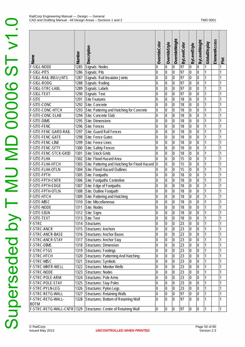
RailCorp Engineering Manual — Design — General CAD and Drafting Manual - All Design Areas – Sections 1 and 2 TMD 0001
Nam
e
Num
ber
Des
crip
tion
Ove
rrid
eCol
or
Ove
rrid
eSty
le
Ove
rrid
eWei
ght
ByL
evel
Col
or
ByL
evel
Styl
e
ByL
evel
Wei
ght
Glo
balD
ispl
ay
Elem
entA
cces
s
Plot
F-SIGL-NODE 1285 Signals: Nodes 0 0 0 97 0 0 1 1 F-SIGL-PITS 1286 Signals: Pits 0 0 0 97 0 0 1 1 F-SIGL-RAIL-INSU-JNTS 1287 Signals: Rail Insulator Joints 0 0 0 97 0 0 1 1 F-SIGL-RODG 1288 Signals: Roding 0 0 0 97 0 0 1 1 F-SIGL-STRC-LABL 1289 Signals: Labels 0 0 0 97 0 0 1 1 F-SIGL-TEXT 1290 Signals: Text 0 0 0 97 0 0 1 1 F-SITE 1291 Site Features 0 0 0 18 0 0 1 1 F-SITE-CONC 1292 Site: Concrete 0 0 0 18 0 0 1 1 F-SITE-CONC-HTCH 1293 Site: Pattering and Hatching for Concrete 0 0 0 18 0 0 1 1 F-SITE-CONC-SLAB 1294 Site: Concrete Slab 0 0 0 18 0 0 1 1 F-SITE-DIMS 1295 Site: Dimensions 0 0 0 18 0 0 1 1 F-SITE-FENC 1296 Site: Fences 0 0 0 18 0 0 1 1 F-SITE-FENC-GARD-RAIL 1297 Site: Guard Rail Fences 0 0 0 18 0 0 1 1 F-SITE-FENC-GATE 1298 Site: Fence Gates 0 0 0 18 0 0 1 1 F-SITE-FENC-LINE 1299 Site: Fence Lines 0 0 0 18 0 0 1 1 F-SITE-FENC-SFTY 1300 Site: Safety Fences 0 0 0 18 0 0 1 1 F-SITE-FENC-STCK-GRID 1301 Site: Stock Grids 0 0 0 18 0 0 1 1 F-SITE-FLHA 1302 Site: Flood Hazard Area 0 0 0 15 0 0 1 1 F-SITE-FLHA-HTCH 1303 Site: Pattering and Hatching for Flood Hazard 0 0 0 15 0 0 1 1 F-SITE-FLHA-OTLN 1304 Site: Flood Hazard Outlines 0 0 0 15 0 0 1 1 F-SITE-FPTH 1305 Site: Footpaths 0 0 0 18 0 0 1 1 F-SITE-FPTH-CNTR 1306 Site: Footpaths Centreline 0 0 0 18 0 0 1 1 F-SITE-FPTH-EDGE 1307 Site: Edge of Footpaths 0 0 0 18 0 0 1 1 F-SITE-FPTH-OTLN 1308 Site: Outline Footpath 0 0 0 18 0 0 1 1 F-SITE-HTCH 1309 Site: Pattering and Hatching 0 0 0 18 0 0 1 1 F-SITE-MISC 1310 Site: Miscellaneous 0 0 0 18 0 0 1 1 F-SITE-NODE 1311 Site: Nodes 0 0 0 18 0 0 1 1 F-SITE-SIGN 1312 Site: Signs 0 0 0 18 0 0 1 1 F-SITE-TEXT 1313 Site: Text 0 0 0 18 0 0 1 1 F-STRC 1314 Structures 0 0 0 23 0 0 1 1 F-STRC-ANCR 1315 Structures: Anchors 0 0 0 23 0 0 1 1 F-STRC-ANCR-BASE 1316 Structures: Anchor Bases 0 0 0 23 0 0 1 1 F-STRC-ANCR-STAY 1317 Structures: Anchor Stay 0 0 0 23 0 0 1 1 F-STRC-DIMS 1318 Structures: Dimension 0 0 0 23 0 0 1 1 F-STRC-FTGS 1319 Structures: Footings 0 0 0 23 0 0 1 1 F-STRC-HTCH 1320 Structures: Patterning And Hatching 0 0 0 23 0 0 1 1 F-STRC-MISC 1321 Structures: Symbols 0 0 0 23 0 0 1 1 F-STRC-MNTR-WELL 1322 Structures: Monitor Wells 0 0 0 23 0 0 1 1 F-STRC-NODE 1323 Structures: Nodes 0 0 0 23 0 0 1 1 F-STRC-POLE-ARM 1324 Structures: Pole Arms 0 0 0 23 0 0 1 1 F-STRC-POLE-STAY 1325 Structures: Stay Poles 0 0 0 23 0 0 1 1 F-STRC-PYLN-LEG 1326 Structures: Pylon Legs 0 0 0 23 0 0 1 1 F-STRC-RETG-WALL 1327 Structures: Retaining Walls 0 0 0 97 0 0 1 1 F-STRC-RETG-WALL-BOTM
1328 Structures: Bottom of Retaining Wall 0 0 0 97 0 0 1 1
F-STRC-RETG-WALL-CNTR 1329 Structures: Centre of Retaining Wall 0 0 0 97 0 0 1 1
© RailCorp Page 50 of 80 Issued May 2013 UNCONTROLLED WHEN PRINTED Version 2.3
Sup
erse
ded
by T
MU
MD
000
06 S
T v1
.0

RailCorp Engineering Manual — Design — General CAD and Drafting Manual - All Design Areas – Sections 1 and 2 TMD 0001
Nam
e
Num
ber
Des
crip
tion
Ove
rrid
eCol
or
Ove
rrid
eSty
le
Ove
rrid
eWei
ght
ByL
evel
Col
or
ByL
evel
Styl
e
ByL
evel
Wei
ght
Glo
balD
ispl
ay
Elem
entA
cces
s
Plot
F-STRC-RETG-WALL-TOP 1330 Structures: Top of Retaining Wall 0 0 0 97 0 0 1 1 F-STRC-STAR 1331 Structures: Stairs 0 0 0 23 0 0 1 1 F-STRC-TANK-UNDR 1332 Structures: Underground Tanks 0 0 0 23 0 0 1 1 F-STRC-TEXT 1333 Structures: Text 0 0 0 23 0 0 1 1 F-STRC-UNID 1334 Structures: Unidentified 0 0 0 23 0 0 1 1 F-STRC-UNID-CABL 1335 Structures: Unidentified Cables 0 0 0 23 0 0 1 1 F-STRC-UNID-PIPE-OVHD 1336 Structures: Unidentified Above-Ground Piping 0 0 0 23 0 0 1 1 F-STRC-UNID-PIPE-UNDR 1337 Structures: Unidentified Underground Piping 0 0 0 23 0 0 1 1 F-STRC-UNID-PITS 1338 Structures Unidentified: Pits 0 0 0 23 0 0 1 1 F-STRC-UNID-POLE 1339 Structures: Unidentified Poles 0 0 0 23 0 0 1 1 F-STRC-UNID-SERV 1340 Structures: Unidentified Services 0 0 0 23 0 0 1 1 F-STRC-WALL-BOTM 1341 Structures: Bottom of Wall 0 0 0 23 0 0 1 1 F-STRC-WALL-TOP 1342 Structures: Top of Wall 0 0 0 23 0 0 1 1 F-STRM 1343 Storm Water Drainage 0 0 0 167 0 0 1 1 F-STRM-CHNL 1344 Storm Water: Drainage Channel 0 0 0 167 0 0 1 1 F-STRM-CNTR 1345 Storm Water: Centreline of Drainage 0 0 0 167 0 0 1 1 F-STRM-DIMS 1346 Storm Water: Dimensions 0 0 0 167 0 0 1 1 F-STRM-HTCH 1347 Storm Water: Patterning and Hatching 0 0 0 167 0 0 1 1 F-STRM-MHOL 1348 Storm Water: Drainage Manhole 0 0 0 167 0 0 1 1 F-STRM-MISC 1349 Storm Water: Miscellaneous 0 0 0 167 0 0 1 1 F-STRM-NODE 1350 Storm Water: Nodes 0 0 0 167 0 0 1 1 F-STRM-OTLN 1351 Storm Water: Drainage Structure Outlines 0 0 0 167 0 0 1 1 F-STRM-PIPE-UNDR 1352 Storm Water: Pipeline Underground 0 0 0 167 0 0 1 1 F-STRM-TEXT 1353 Storm Water: Text 0 0 0 167 0 0 1 1 F-SURV 1354 Survey 0 0 0 0 0 0 1 1 F-SURV-CTRL-LABL 1355 Survey: Control Label Text 0 0 0 0 0 0 1 1 F-SURV-CTRL-MARK 1356 Survey: Control Marks 0 0 0 0 0 0 1 1 F-SURV-CTRL-MARK-BNCH
1357 Survey: Bench Marks 0 0 0 0 0 0 1 1
F-SURV-CTRL-MARK-DHOL 1358 Survey: Drill Hole and Wing Marks 0 0 0 0 0 0 1 1 F-SURV-CTRL-MARK-NAIL 1359 Survey: Ram Set Nail Marks 0 0 0 0 0 0 1 1 F-SURV-CTRL-MARK-STAT 1360 Survey: State Survey Marks 0 0 0 0 0 0 1 1 F-SURV-CTRL-MARK-SUBS 1361 Survey: Substantial Survey Marks 0 0 0 0 0 0 1 1 F-SURV-CTRL-MARK-TEMP 1362 Survey: Temporary Survey Marks 0 0 0 0 0 0 1 1 F-SURV-CTRL-MARK-TRAK 1363 Survey: Track Control Marks 0 0 0 0 0 0 1 1 F-SURV-CTRL-TRAV 1364 Survey: Traverse Linework 0 0 0 0 0 0 1 1 F-SURV-DATA-DESC 1365 Survey: Data Descriptions 0 0 0 0 0 0 1 1 F-SURV-DATA-ELEV 1366 Survey: Data Elevations 0 0 0 0 0 0 1 1 F-SURV-DATA-MARK 1367 Survey: Data Mark 0 0 0 0 0 0 1 1 F-SURV-DATA-NUMB 1368 Survey: Data Number 0 0 0 0 0 0 1 1 F-SURV-DIMS 1369 Survey: Dimensions 0 0 0 0 0 0 1 1 F-SURV-EXTS 1370 Survey: Extents 0 0 0 0 0 0 1 1 F-SURV-NODE 1371 Survey: Nodes 0 0 0 0 0 0 1 1 F-SURV-SCHD 1372 Survey: Schedules 0 0 0 0 0 0 1 1 F-SURV-SYMB 1373 Survey: Symbols 0 0 0 0 0 0 1 1 F-SURV-TEXT 1374 Survey: General Text 0 0 0 0 0 0 1 1
© RailCorp Page 51 of 80 Issued May 2013 UNCONTROLLED WHEN PRINTED Version 2.3
Sup
erse
ded
by T
MU
MD
000
06 S
T v1
.0

RailCorp Engineering Manual — Design — General CAD and Drafting Manual - All Design Areas – Sections 1 and 2 TMD 0001
© RailCorp Page 52 of 80 Issued May 2013 UNCONTROLLED WHEN PRINTED Version 2.3
Nam
e
Num
ber
Des
crip
tion
Ove
rrid
eCol
or
Ove
rrid
eSty
le
Ove
rrid
eWei
ght
ByL
evel
Col
or
ByL
evel
Styl
e
ByL
evel
Wei
ght
Glo
balD
ispl
ay
Elem
entA
cces
s
Plot
F-TRAF 1375 Traffic Authority (RTA) 0 0 0 173 0 0 1 1 F-TRAF-CABL 1376 Traffic Authority: Cables 0 0 0 173 0 0 1 1 F-TRAF-CABL-UNDR 1377 Traffic Authority: Underground Cables 0 0 0 173 0 0 1 1 F-TRAF-DIMS 1378 Traffic Authority: Dimensions 0 0 0 173 0 0 1 1 F-TRAF-HTCH 1379 Traffic Authority: Pattering and Hatching 0 0 0 173 0 0 1 1 F-TRAF-LGHT 1380 Traffic Authority: Traffic Lights 0 0 0 173 0 0 1 1 F-TRAF-MHOL 1381 Traffic Authority: Manholes 0 0 0 173 0 0 1 1 F-TRAF-MISC 1382 Traffic Authority: Miscellaneous 0 0 0 173 0 0 1 1 F-TRAF-NODE 1383 Traffic Authority: Nodes 0 0 0 173 0 0 1 1 F-TRAF-PEDS-XING 1384 Traffic Authority: Pedestrian Xings 0 0 0 173 0 0 1 1 F-TRAF-SIGL-JNCT-BOX 1385 Traffic Authority: Signal Junction Box 0 0 0 173 0 0 1 1 F-TRAF-STRC 1386 Traffic Authority: Structures 0 0 0 173 0 0 1 1 F-TRAF-TEXT 1387 Traffic Authority: Text 0 0 0 173 0 0 1 1 F-TRAK 1388 Trackwork 0 0 0 161 0 0 1 1 F-TRAK-BLST 1389 Trackwork: Ballast 0 0 0 11 0 0 1 1 F-TRAK-BLST-BOTM 1390 Trackwork: Bottom of Ballast 0 0 0 11 0 0 1 1 F-TRAK-BLST-SURF 1391 Trackwork: Ballast Surfaces 0 0 0 11 0 0 1 1 F-TRAK-BLST-SURF-CONR 1392 Trackwork: Ballast Surface Contours 0 0 0 11 0 0 1 1 F-TRAK-BLST-SURF-SYMB 1393 Trackwork: Ballast Surface Symbology 0 0 0 11 0 0 1 1 F-TRAK-BLST-TEXT 1394 Trackwork: Ballast Text 0 0 0 11 0 0 1 1 F-TRAK-BLST-TOP 1395 Trackwork: Top of Ballast 0 0 0 11 0 0 1 1 F-TRAK-CNTR 1396 Trackwork: Centreline 0 0 0 161 0 0 1 1 F-TRAK-DIMS 1397 Trackwork: Dimensions 0 0 0 161 0 0 1 1 F-TRAK-EQPT 1398 Trackwork: Equipment 0 0 0 161 0 0 1 1 F-TRAK-HTCH 1399 Trackwork: Patterning and Hatching 0 0 0 161 0 0 1 1 F-TRAK-LABL 1400 Trackwork: Track Name Labels 0 0 0 161 0 0 1 1 F-TRAK-LEVL-XING 1401 Trackwork: Level Xings 0 0 0 161 0 0 1 1 F-TRAK-LEVL-XING-HTCH 1402 Trackwork: Patterning and Hatching (Level
Xing) 0 0 0 161 0 0 1 1
F-TRAK-LEVL-XING-SURF 1403 Trackwork: Level Xing Surface Details 0 0 0 161 0 0 1 1 F-TRAK-LEVL-XING-TEXT 1404 Trackwork: Level Xing Text 0 0 0 161 0 0 1 1 F-TRAK-NODE 1405 Trackwork: Nodes 0 0 0 161 0 0 1 1 F-TRAK-RAIL 1406 Trackwork: Rails (Running Face) 0 0 0 161 0 0 1 1 F-TRAK-RAIL-CHEK 1407 Trackwork: Check Rails 0 0 0 161 0 0 1 1 F-TRAK-RAIL-CNTR-PNT 1408 Trackwork: Point on CL of Rails 0 0 0 161 0 0 1 1 F-TRAK-RAIL-DN 1409 Trackwork: Down Rail Running Face 0 0 0 161 0 0 1 1 F-TRAK-RAIL-HTCH 1410 Trackwork: Rail Patterning and Hatching 0 0 0 161 0 0 1 1 F-TRAK-RAIL-INSU-SYMB 1411 Trackwork: Rail Insulator Symbols 0 0 0 161 0 0 1 1 F-TRAK-RAIL-MISC 1412 Trackwork: Rail Symbols 0 0 0 161 0 0 1 1 F-TRAK-RAIL-PNT 1413 Trackwork: Point on Rail 0 0 0 161 0 0 1 1 F-TRAK-RAIL-SURF 1414 Trackwork: Rail Surface Details 0 0 0 161 0 0 1 1 F-TRAK-RAIL-TEXT 1415 Trackwork: Rail Text 0 0 0 161 0 0 1 1 F-TRAK-RAIL-UP 1416 Trackwork: Up Rail Running Face 0 0 0 161 0 0 1 1 F-TRAK-SLPR 1417 Trackwork: Sleepers 0 0 0 161 0 0 1 1 F-TRAK-SLPR-CNTR 1418 Trackwork: Sleeper Centreline 0 0 0 161 0 0 1 1 F-TRAK-SLPR-SURF 1419 Trackwork: Sleeper Surface Details 0 0 0 161 0 0 1 1
Sup
erse
ded
by T
MU
MD
000
06 S
T v1
.0

RailCorp Engineering Manual — Design — General CAD and Drafting Manual - All Design Areas – Sections 1 and 2 TMD 0001
Nam
e
Num
ber
Des
crip
tion
Ove
rrid
eCol
or
Ove
rrid
eSty
le
Ove
rrid
eWei
ght
ByL
evel
Col
or
ByL
evel
Styl
e
ByL
evel
Wei
ght
Glo
balD
ispl
ay
Elem
entA
cces
s
Plot
F-TRAK-SLPR-TEXT 1420 Trackwork: Sleeper Text 0 0 0 161 0 0 1 1 F-TRAK-STRC-BUFR-STOP 1421 Trackwork: Buffer Stop Structures 0 0 0 161 0 0 1 1 F-TRAK-TEXT 1422 Trackwork: Text 0 0 0 161 0 0 1 1 F-TRAK-TRNO 1423 Trackwork: Turnouts 0 0 0 1 0 0 1 1 F-TRAK-TRNO-CNTR 1424 Trackwork: Turnout Centrelines 0 0 0 1 0 0 1 1 F-TRAK-TRNO-LABL 1425 Trackwork: Turnout Labels 0 0 0 1 0 0 1 1 F-TRAK-TRNO-MISC 1426 Trackwork: Turnouts Miscellaneous 0 0 0 1 0 0 1 1 F-TRAK-TRNO-PNTS 1427 Trackwork: Turnout Points 0 0 0 1 0 0 1 1 F-TRAK-TRNO-TEXT 1428 Trackwork: Turnout Text 0 0 0 1 0 0 1 1 F-TRAK-TRNO-XING-PNT 1429 Trackwork: Turnout Xing Point 0 0 0 1 0 0 1 1 F-TUNL 1430 Tunnels 0 0 0 19 0 0 1 1 F-TUNL-CNTR 1431 Tunnels: Centreline 0 0 0 19 0 0 1 1 F-TUNL-DIMS 1432 Tunnels: Surfaces 0 0 0 19 0 0 1 1 F-TUNL-HTCH 1433 Tunnels: Patterning and Hatching 0 0 0 19 0 0 1 1 F-TUNL-MISC 1434 Tunnels: Symbols 0 0 0 19 0 0 1 1 F-TUNL-NODE 1435 Tunnels: Nodes 0 0 0 19 0 0 1 1 F-TUNL-OTLN 1436 Tunnels: Outlines 0 0 0 19 0 0 1 1 F-TUNL-SURF 1437 Tunnels: Surfaces 0 0 0 19 0 0 1 1 F-TUNL-SURF-CONR 1438 Tunnels: Surfaces 0 0 0 19 0 0 1 1 F-TUNL-SURF-SYMB 1439 Tunnels: Surfaces 0 0 0 19 0 0 1 1 F-TUNL-TEXT 1440 Tunnels: Text 0 0 0 19 0 0 1 1 F-TUNL-WALL 1441 Tunnels: Line of Walls 0 0 0 19 0 0 1 1 F-TUNL-WALL-PNT 1442 Tunnels: Points on Wall 0 0 0 19 0 0 1 1 F-UTIL-CAIR 1443 Compressed Air 0 0 0 97 0 0 1 1 F-UTIL-CAIR-DIMS 1444 Compressed Air: Dimensions 0 0 0 97 0 0 1 1 F-UTIL-CAIR-MHOL 1445 Compressed Air: Manhole 0 0 0 97 0 0 1 1 F-UTIL-CAIR-MISC 1446 Compressed Air: Symbols 0 0 0 97 0 0 1 1 F-UTIL-CAIR-NODE 1447 Compressed Air: Nodes 0 0 0 97 0 0 1 1 F-UTIL-CAIR-PIPE 1448 Compressed Air: Pipeline 0 0 0 97 0 0 1 1 F-UTIL-CAIR-PIPE-UNDR 1449 Compressed Air: Underground Pipeline 0 0 0 97 0 0 1 1 F-UTIL-CAIR-TEXT 1450 Compressed Air: Text 0 0 0 97 0 0 1 1 F-UTIL-CAIR-VALV 1451 Compressed Air: Valve 0 0 0 97 0 0 1 1 F-UTIL-COMS 1452 Utilities Communication 0 0 0 14 0 0 1 1 F-UTIL-COMS-DIMS 1453 Utilities Communication: Dimensions 0 0 0 14 0 0 1 1 F-UTIL-COMS-DUCT 1454 Utilities Comm's: Conduits 0 0 0 14 0 0 1 1 F-UTIL-COMS-MHOL 1455 Utilities Comm's: Manhole 0 0 0 14 0 0 1 1 F-UTIL-COMS-MISC 1456 Utilities Comm's: Marker 0 0 0 14 0 0 1 1 F-UTIL-COMS-NODE 1457 Utilities Comm's: Nodes 0 0 0 14 0 0 1 1 F-UTIL-COMS-TEXT 1458 Utilities Comm's: Text 0 0 0 14 0 0 1 1 F-UTIL-COMS-UNDR 1459 Utilities Comm's: Underground 0 0 0 14 0 0 1 1 F-UTIL-FUEL 1460 Utilities Fuel Gas 0 0 0 21 0 0 1 1 F-UTIL-FUEL-DIMS 1461 Utilities Fuel Gas: Dimensions 0 0 0 21 0 0 1 1 F-UTIL-FUEL-HPRE-MRKR 1462 Utilities Fuel Gas: High Pressure Markers 0 0 0 21 0 0 1 1 F-UTIL-FUEL-MHOL 1463 Utilities Fuel Gas: Manhole 0 0 0 21 0 0 1 1 F-UTIL-FUEL-MISC 1464 Utilities Fuel Gas: Fittings, Valves, Markers 0 0 0 21 0 0 1 1 F-UTIL-FUEL-NODE 1465 Utilities Fuel Gas: Nodes 0 0 0 21 0 0 1 1
© RailCorp Page 53 of 80 Issued May 2013 UNCONTROLLED WHEN PRINTED Version 2.3
Sup
erse
ded
by T
MU
MD
000
06 S
T v1
.0

RailCorp Engineering Manual — Design — General CAD and Drafting Manual - All Design Areas – Sections 1 and 2 TMD 0001
© RailCorp Page 54 of 80 Issued May 2013 UNCONTROLLED WHEN PRINTED Version 2.3
Nam
e
Num
ber
Des
crip
tion
Ove
rrid
eCol
or
Ove
rrid
eSty
le
Ove
rrid
eWei
ght
ByL
evel
Col
or
ByL
evel
Styl
e
ByL
evel
Wei
ght
Glo
balD
ispl
ay
Elem
entA
cces
s
F-UTIL-FUEL-PIPE 1466 Utilities Fuel Gas: Pipeline 0 0 0 21 0 0 1 1 F-UTIL-FUEL-PIPE-UNDR 1467 Utilities Fuel Gas: Underground Pipeline 0 0 0 21 0 0 1 1F-UTIL-FUEL-TEXT 1468 Utilities Fuel Gas: Text 0 0 0 21 0 0 1 1 F-UTIL-NGAS 1469 Utilities Natural Gas 0 0 0 53 0 0 1 1F-UTIL-NGAS-DIMS 1470 Utilities Natural Gas: Dimensions 0 0 0 53 0 0 1 1F-UTIL-NGAS-HPRE-MRKR 1471 Utilities Natural Gas: High Pressure Markers 0 0 0 53 0 0 1 1 F-UTIL-NGAS-METR 1472 Utilities Natural Gas 0 0 0 53 0 0 1 1F-UTIL-NGAS-MHOL 1473 Utilities Natural Gas: Manhole 0 0 0 53 0 0 1 1F-UTIL-NGAS-MHOL-COVR 1474 Utilities Natural Gas: Manhole Cover 0 0 0 53 0 0 1 1 F-UTIL-NGAS-MISC 1475 Utilities Natural Gas: Miscellaneous 0 0 0 53 0 0 1 1F-UTIL-NGAS-NODE 1476 Utilities Natural Gas: Nodes 0 0 0 53 0 0 1 1F-UTIL-NGAS-PIPE 1477 Utilities Natural Gas: Pipeline 0 0 0 53 0 0 1 1F-UTIL-NGAS-PIPE-MRKR 1478 Utilities Natural Gas: Pipeline Markers 0 0 0 53 0 0 1 1F-UTIL-NGAS-PIPE-UNDR 1479 Utilities Natural Gas: Pipeline Underground 0 0 0 53 0 0 1 1 F-UTIL-NGAS-REGL-BOX 1480 Utilities Natural Gas: Regulator Boxes 0 0 0 53 0 0 1 1F-UTIL-NGAS-TEST-PNT 1481 Utilities Natural Gas: Test Points 0 0 0 53 0 0 1 1 F-UTIL-NGAS-TEXT 1482 Utilities Natural Gas: Text 0 0 0 53 0 0 1 1F-UTIL-NGAS-VALV-BOX 1483 Utilities Natural Gas: Valve Box 0 0 0 53 0 0 1 1 F-UTIL-NGAS-VENT 1484 Utilities Natural Gas: Vent Points 0 0 0 53 0 0 1 1 F-UTIL-OPTC 1485 Utilities, Optic Fibre 0 0 0 12 0 0 1 1F-UTIL-OPTC-CABL 1486 Utilities, Optic Fibre: Cables 0 0 0 12 0 0 1 1 F-UTIL-OPTC-CABL-MRKR 1487 Utilities, Optic Fibre: Cable Markers 0 0 0 12 0 0 1 1 F-UTIL-OPTC-CABL-PITS 1488 Utilities, Optic Fibre: Cable Pits 0 0 0 12 0 0 1 1 F-UTIL-OPTC-CABL-UNDR 1489 Utilities, Optic Fibre: Underground Cables 0 0 0 12 0 0 1 1F-UTIL-OPTC-DIMS 1490 Utilities, Optic Fibre: Dimensions 0 0 0 12 0 0 1 1F-UTIL-OPTC-HTCH 1491 Utilities, Optic Fibre: Pattering and Hatching 0 0 0 12 0 0 1 1 F-UTIL-OPTC-JNCT-BOX 1492 Utilities, Optic Fibre: Junction Box 0 0 0 12 0 0 1 1 F-UTIL-OPTC-NODE 1493 Utilities, Optic Fibre: Nodes 0 0 0 12 0 0 1 1 F-UTIL-OPTC-TEXT 1494 Utilities, Optic Fibre: Text 0 0 0 12 0 0 1 1 F-UTIL-POWR 1495 Utilities Power 0 0 0 114 0 0 1 1F-UTIL-POWR-CABL 1496 Utilities Power: Cables 0 0 0 114 0 0 1 1F-UTIL-POWR-CABL-UNDR 1497 Utilities Power: Cables Underground 0 0 0 114 0 0 1 1F-UTIL-POWR-DIMS 1498 Utilities Power: Dimensions 0 0 0 114 0 0 1 1F-UTIL-POWR-DSTB-FUSE 1499 Utilities Power: Distribution Fuse 0 0 0 114 0 0 1 1F-UTIL-POWR-FENC 1500 Utilities Power: Fence Enclosure 0 0 0 114 0 0 1 1F-UTIL-POWR-FITT 1501 Utilities Power: Fittings 0 0 0 114 0 0 1 1F-UTIL-POWR-JNCT-BOX 1502 Utilities Power: Junction Box 0 0 0 114 0 0 1 1F-UTIL-POWR-LGHT 1503 Utilities Power: Light 0 0 0 114 0 0 1 1F-UTIL-POWR-MHOL 1504 Utilities Power: Manholes 0 0 0 114 0 0 1 1F-UTIL-POWR-MISC 1505 Utilities Power: Miscellaneous 0 0 0 114 0 0 1 1F-UTIL-POWR-NODE 1506 Utilities Power: Nodes 0 0 0 114 0 0 1 1F-UTIL-POWR-PILR-UNDR 1507 Utilities Power: Underground Pillar 0 0 0 114 0 0 1 1F-UTIL-POWR-POLE 1508 Utilities Power: Poles 0 0 0 114 0 0 1 1F-UTIL-POWR-POLE-ELEC 1509 Utilities Power: Electric Light Pole 0 0 0 114 0 0 1 1F-UTIL-POWR-POLE-LGHT 1510 Utilities Power: Light on Pole 0 0 0 114 0 0 1 1 F-UTIL-POWR-POLE-TRFM 1511 Utilities Power: Transformer Pole 0 0 0 114 0 0 1 1
Plot
Sup
erse
ded
by T
MU
MD
000
06 S
T v1
.0
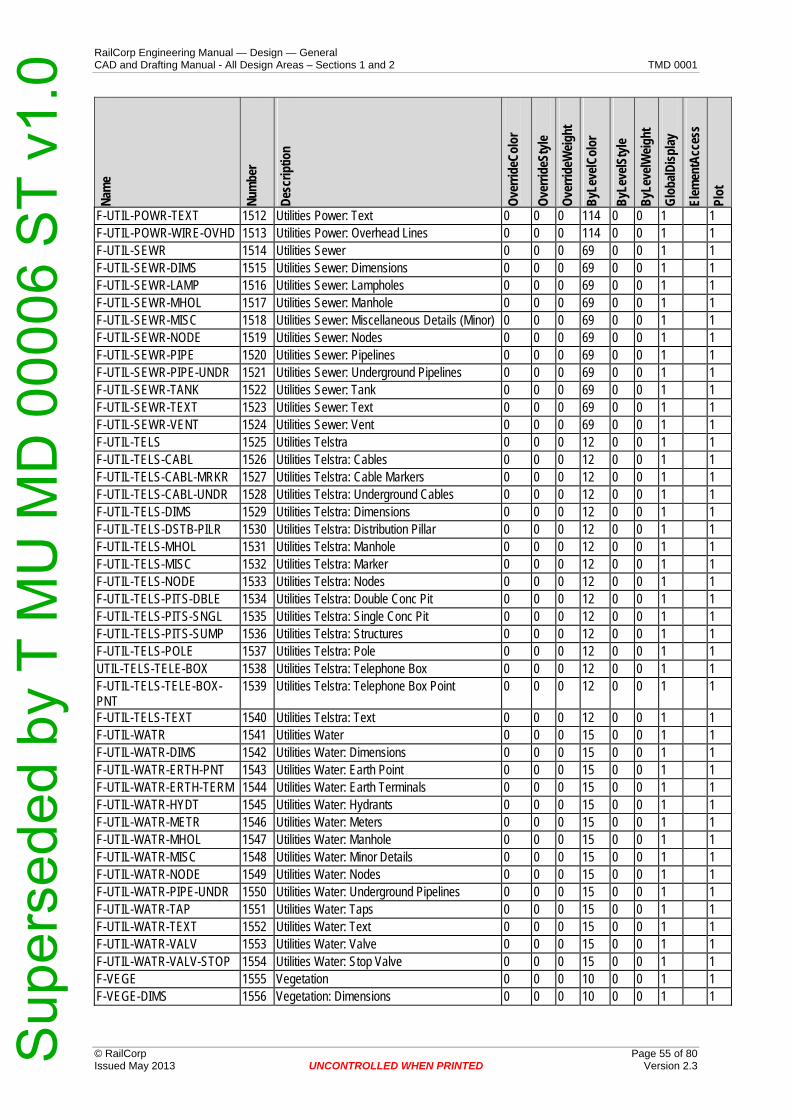
RailCorp Engineering Manual — Design — General CAD and Drafting Manual - All Design Areas – Sections 1 and 2 TMD 0001
© RailCorp Page 55 of 80 Issued May 2013 UNCONTROLLED WHEN PRINTED Version 2.3
Nam
e
Num
ber
Des
crip
tion
Ove
rrid
eCol
or
Ove
rrid
eSty
le
Ove
rrid
eWei
ght
ByL
evel
Col
or
ByL
evel
Styl
e
ByL
evel
Wei
ght
Glo
balD
ispl
ay
Elem
entA
cces
s
Plot
F-UTIL-POWR-TEXT 1512 Utilities Power: Text 0 0 0 114 0 0 1 1 F-UTIL-POWR-WIRE-OVHD 1513 Utilities Power: Overhead Lines 0 0 0 114 0 0 1 1 F-UTIL-SEWR 1514 Utilities Sewer 0 0 0 69 0 0 1 1 F-UTIL-SEWR-DIMS 1515 Utilities Sewer: Dimensions 0 0 0 69 0 0 1 1 F-UTIL-SEWR-LAMP 1516 Utilities Sewer: Lampholes 0 0 0 69 0 0 1 1 F-UTIL-SEWR-MHOL 1517 Utilities Sewer: Manhole 0 0 0 69 0 0 1 1 F-UTIL-SEWR-MISC 1518 Utilities Sewer: Miscellaneous Details (Minor) 0 0 0 69 0 0 1 1 F-UTIL-SEWR-NODE 1519 Utilities Sewer: Nodes 0 0 0 69 0 0 1 1 F-UTIL-SEWR-PIPE 1520 Utilities Sewer: Pipelines 0 0 0 69 0 0 1 1 F-UTIL-SEWR-PIPE-UNDR 1521 Utilities Sewer: Underground Pipelines 0 0 0 69 0 0 1 1 F-UTIL-SEWR-TANK 1522 Utilities Sewer: Tank 0 0 0 69 0 0 1 1 F-UTIL-SEWR-TEXT 1523 Utilities Sewer: Text 0 0 0 69 0 0 1 1 F-UTIL-SEWR-VENT 1524 Utilities Sewer: Vent 0 0 0 69 0 0 1 1 F-UTIL-TELS 1525 Utilities Telstra 0 0 0 12 0 0 1 1 F-UTIL-TELS-CABL 1526 Utilities Telstra: Cables 0 0 0 12 0 0 1 1 F-UTIL-TELS-CABL-MRKR 1527 Utilities Telstra: Cable Markers 0 0 0 12 0 0 1 1 F-UTIL-TELS-CABL-UNDR 1528 Utilities Telstra: Underground Cables 0 0 0 12 0 0 1 1 F-UTIL-TELS-DIMS 1529 Utilities Telstra: Dimensions 0 0 0 12 0 0 1 1 F-UTIL-TELS-DSTB-PILR 1530 Utilities Telstra: Distribution Pillar 0 0 0 12 0 0 1 1 F-UTIL-TELS-MHOL 1531 Utilities Telstra: Manhole 0 0 0 12 0 0 1 1 F-UTIL-TELS-MISC 1532 Utilities Telstra: Marker 0 0 0 12 0 0 1 1 F-UTIL-TELS-NODE 1533 Utilities Telstra: Nodes 0 0 0 12 0 0 1 1 F-UTIL-TELS-PITS-DBLE 1534 Utilities Telstra: Double Conc Pit 0 0 0 12 0 0 1 1 F-UTIL-TELS-PITS-SNGL 1535 Utilities Telstra: Single Conc Pit 0 0 0 12 0 0 1 1 F-UTIL-TELS-PITS-SUMP 1536 Utilities Telstra: Structures 0 0 0 12 0 0 1 1 F-UTIL-TELS-POLE 1537 Utilities Telstra: Pole 0 0 0 12 0 0 1 1 UTIL-TELS-TELE-BOX 1538 Utilities Telstra: Telephone Box 0 0 0 12 0 0 1 1 F-UTIL-TELS-TELE-BOX-PNT
1539 Utilities Telstra: Telephone Box Point 0 0 0 12 0 0 1 1
F-UTIL-TELS-TEXT 1540 Utilities Telstra: Text 0 0 0 12 0 0 1 1 F-UTIL-WATR 1541 Utilities Water 0 0 0 15 0 0 1 1 F-UTIL-WATR-DIMS 1542 Utilities Water: Dimensions 0 0 0 15 0 0 1 1 F-UTIL-WATR-ERTH-PNT 1543 Utilities Water: Earth Point 0 0 0 15 0 0 1 1 F-UTIL-WATR-ERTH-TERM 1544 Utilities Water: Earth Terminals 0 0 0 15 0 0 1 1 F-UTIL-WATR-HYDT 1545 Utilities Water: Hydrants 0 0 0 15 0 0 1 1 F-UTIL-WATR-METR 1546 Utilities Water: Meters 0 0 0 15 0 0 1 1 F-UTIL-WATR-MHOL 1547 Utilities Water: Manhole 0 0 0 15 0 0 1 1 F-UTIL-WATR-MISC 1548 Utilities Water: Minor Details 0 0 0 15 0 0 1 1 F-UTIL-WATR-NODE 1549 Utilities Water: Nodes 0 0 0 15 0 0 1 1 F-UTIL-WATR-PIPE-UNDR 1550 Utilities Water: Underground Pipelines 0 0 0 15 0 0 1 1 F-UTIL-WATR-TAP 1551 Utilities Water: Taps 0 0 0 15 0 0 1 1 F-UTIL-WATR-TEXT 1552 Utilities Water: Text 0 0 0 15 0 0 1 1 F-UTIL-WATR-VALV 1553 Utilities Water: Valve 0 0 0 15 0 0 1 1 F-UTIL-WATR-VALV-STOP 1554 Utilities Water: Stop Valve 0 0 0 15 0 0 1 1 F-VEGE 1555 Vegetation 0 0 0 10 0 0 1 1 F-VEGE-DIMS 1556 Vegetation: Dimensions 0 0 0 10 0 0 1 1
Sup
erse
ded
by T
MU
MD
000
06 S
T v1
.0
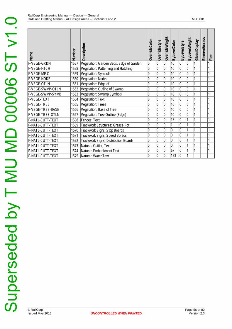
RailCorp Engineering Manual — Design — General CAD and Drafting Manual - All Design Areas – Sections 1 and 2 TMD 0001
Nam
e
Num
ber
Des
crip
tion
Ove
rrid
eCol
or
Ove
rrid
eSty
le
Ove
rrid
eWei
ght
ByL
evel
Col
or
ByL
evel
Styl
e
ByL
evel
Wei
ght
Glo
balD
ispl
ay
Elem
entA
cces
s
Plot
F-VEGE-GRDN 1557 Vegetation: Garden Beds, Edge of Garden 0 0 0 10 0 0 1 1 F-VEGE-HTCH 1558 Vegetation: Patterning and Hatching 0 0 0 10 0 0 1 1 F-VEGE-MISC 1559 Vegetation: Symbols 0 0 0 10 0 0 1 1 F-VEGE-NODE 1560 Vegetation: Nodes 0 0 0 10 0 0 1 1 F-VEGE-OTLN 1561 Vegetation: Edge of 0 0 0 10 0 0 1 1 F-VEGE-SWMP-OTLN 1562 Vegetation: Outline of Swamp 0 0 0 10 0 0 1 1 F-VEGE-SWMP-SYMB 1563 Vegetation: Swamp Symbols 0 0 0 10 0 0 1 1 F-VEGE-TEXT 1564 Vegetation: Text 0 0 0 10 0 0 1 1 F-VEGE-TREE 1565 Vegetation: Trees 0 0 0 10 0 0 1 1 F-VEGE-TREE-BASE 1566 Vegetation: Base of Tree 0 0 0 10 0 0 1 1 F-VEGE-TREE-OTLN 1567 Vegetation: Tree Outline (Edge) 0 0 0 10 0 0 1 1 F-NATL-CUTT-TEXT 1568 Fences: Text 0 0 0 13 0 1 1 1 F-NATL-CUTT-TEXT 1569 Trackwork Structures: Grease Pot 0 0 0 1 0 1 1 1 F-NATL-CUTT-TEXT 1570 Trackwork Signs: Stop Boards 0 0 0 0 0 1 1 1 F-NATL-CUTT-TEXT 1571 Trackwork Signs: Speed Borads 0 0 0 0 0 1 1 1 F-NATL-CUTT-TEXT 1572 Trackwork Signs: Distribution Boards 0 0 0 0 0 1 1 1 F-NATL-CUTT-TEXT 1573 Natural: Cutting Text 0 0 0 0 0 1 1 1 F-NATL-CUTT-TEXT 1574 Natural: Embankment Text 0 0 0 67 0 1 1 1 F-NATL-CUTT-TEXT 1575 Natural: Water Text 0 0 0 153 0 1
© RailCorp Page 56 of 80 Issued May 2013 UNCONTROLLED WHEN PRINTED Version 2.3
Sup
erse
ded
by T
MU
MD
000
06 S
T v1
.0

RailCorp Engineering Manual — Design — General CAD and Drafting Manual - All Design Areas – Sections 1 and 2 TMD 0001
© RailCorp Page 57 of 80 Issued May 2013 UNCONTROLLED WHEN PRINTED Version 2.3
Appendix C CAD File Naming Conventions
1.1 Overview
The efficient sharing and transfer of CAD Information from external and internal clients from designers relies on the use of a systematic file naming convention.
This section refers to CAD file naming conventions only and should not be confused with the EDMS drawing numbering convention.
For Drawing Numbers, please refer to EDMS System.
The majority of CAD Files can be broken up into 2 categories:
Project (Job) Related Cad Files NON Project (Repository) Related Files
All drawing, model and design data file names shall be structured in the format set out in this section.
1.1.1 Definitions
CAD Computer Aided Drafting/Design
InRail Civil Track Design Application used by RailCorp Engineering Design.
MicroStation CAD Application used by RailCorp Engineering Design.
DGN MicroStation Design File
PID Project Identifier
Project Related Files Cad Files that are directly associated with CAD Projects, that is, constructed and stored within, remaining within for life of project.
Non-Project Files All other CAD Files not directly associated with a CAD project, Current Design Models, As-Built Modes, Grid Files, Mapping, etc.
CAD Model Files Electronic CAD Models built from data to form intelligent data that is globally shared and used to construct CAD Drawing Document Files.
CAD Drawing Files Electronic CAD File that produces documented output drawings that are signed and lodged in plan room.
Design Models Internal MicroStation File Model that contains geo-referenced / feature data used for reference to sheet models, will be found in both CAD DGN model files and CAD Drawings Files.
Sheet Models Internal MicroStation File Model that contains the drawing frame with referenced data used to create a drawing document, found only in the CAD Drawing Files.
Data The term ‘data’ generally refers to any electronic file produced for a project. The term ‘design data’ or ‘design’ usually refers to the CAD ‘vector’ file format primarily being (Bentley) MicroStation .DGN or otherwise (Autodesk) AutoCAD .DWG. Design data may also refer generally to ‘vector’ data file content or line-based drawings and models.
Sup
erse
ded
by T
MU
MD
000
06 S
T v1
.0

RailCorp Engineering Manual — Design — General CAD and Drafting Manual - All Design Areas – Sections 1 and 2 TMD 0001
© RailCorp Page 58 of 80 Issued May 2013 UNCONTROLLED WHEN PRINTED Version 2.3
1.1.2 CAD File Naming Format
1.1.2.1 The standard CAD file name is defined by 7 main components that give the name some visual intelligence.
Each component is described in more detail below.
The text format for the file name shall be in upper case only. The underbar (_) shall be used to separate file name components, not the dash (or minus ‘-‘) character.
Standard File Format:
Discipline Type File Identifier
AmendmentFile Purpose
Optional Detail
File Extension
A _AA[A] _AAAAAAA AA _AA [_AAA..] .ext
1.1.2.2 Discipline Component
The 1st component of the file name is recorded using a single digit alpha code. The discipline identifies the Engineering discipline the file belongs to and is only required for CAD Drawing Files.
Note: For CAD model files, this file name component is NOT required.
For Discipline Code listing see Part B - Design Discipline Codes (Table 9) for details.
1.1.2.3 Type Component
The 2nd component of the file name is recorded using alpha values. The Type component identifies the type of drawing or model file based on the content of the file.
For Drawing Files, a 2-digit code listing of particular drawing types exists for each discipline (see Part D – CAD Drawing File Types (Table 11) to (Table 18) details) and will indicate the type of drawing file.
For Model Files, at 3-digit code listing of particular model types (see Part F – CAD Model File Types (Table 20) will indicate the type of model file.
1.1.2.4 File Identifier Component
The 3rd component of the file name is recorded using an alphanumeric code. The identifier component indicates either a reference to an EDMS number for a drawing file or a reference to an infrastructure feature object for model files.
For drawing files, the 7-digit EDMS number shall be adopted as the drawing files name identifier.
For Model files, a relevant ID label associated with the particular feature shall be adopted as the model files name identifier.
1.1.2.5 Amendment Component
The 4th component of the file name comprises two parts, Major and Minor amendment. The Major amendment is recorded using a 2-digit alpha code. The Major amendment component shows the current approved amendment of the design. The Major amendment alpha character starts with the letter ‘A’ through to “Z” and then “AA, AB…... to ZZ”.
Sup
erse
ded
by T
MU
MD
000
06 S
T v1
.0

RailCorp Engineering Manual — Design — General CAD and Drafting Manual - All Design Areas – Sections 1 and 2 TMD 0001
© RailCorp Page 59 of 80 Issued May 2013 UNCONTROLLED WHEN PRINTED Version 2.3
Revision ID Description
_A or AA [NNN] Design Version Character
The Minor amendment number is recorded using a 3-digit numeric code. This minor number is optional and is only used when there is a need to differentiate between various stages of an amendment. The minor amendment number starts at 1 and can go as high as 999.
Revision ID Description
NNN Design Version Number Alpha Numeric
1.1.2.6 File Purpose Component
The 5th component of the file name is recorded using a 2-digit alphanumeric code. The file purpose indicates the purpose of the CAD file, be it stage of design or source of data, etc, see Part C – Document Purpose Codes (Table 10) for code listing.
1.1.2.7 Optional Detail Component
The 6th component of the file name is recorded using an alphanumeric code. The optional detail code indicates more specific details about the particular type of file (Overbridge, Location, etc).
For requirements please refer to discipline section of Cad Manual for more details.
Note: This file name component is optional across all Engineering disciplines, with the exception being the Architectural discipline where it is mandatory.
1.1.2.8 File Extension
The 7th component of the file name is recorded using a 3-digit alpha code (file extension). Depending upon the type of file produced the file extension will differ. Typical CAD (vector) file extension include .DGN, .DWG and .DXF. Typically image (raster, or pixel based matrix data) files include extensions such as .TIF, .JPG, .BMP and .GIF.
1.1.3 CAD Projects
1.1.3.1 CAD Project Identifier Format
By design, the PID (Project Identifier) naming format allows the viewer to obtain from the PID number, a track corridor relationship for the project and the year in which the project was created.
The Project Identifier Naming format should indicate the Design Discipline Code, a 2 digit numeric code for the Year (Date) of Creation, a 3 digit alphanumeric code indicating the Track Corridor, and a 2 digit sequential code insuring that each project identifier number is unique.
Naming Format:
Sup
erse
ded
by T
MU
MD
000
06 S
T v1
.0

RailCorp Engineering Manual — Design — General CAD and Drafting Manual - All Design Areas – Sections 1 and 2 TMD 0001
© RailCorp Page 60 of 80 Issued May 2013 UNCONTROLLED WHEN PRINTED Version 2.3
A YY ANN NN
Discipline Year of Creation
Track Corridor Sequential Number
Character Description
Discipline Design Discipline Character Code, see Part B - Design Discipline Codes (Table 9)
Year of Creation
Creation Date (2 Digit Year)
Track Corridor Track Corridor Identifier Code, see Part G – Track Corridor Line Codes (Table 21) or RailCorp Intranet for Track Data Area for Codes
Sequential Number
Sequential Project 2 digit numeric code
PID Examples:
R05M2405
(Global Design Project, 2005, Bankstown Line, 05 Record Number)
C05M0101
(Civil Design Project, 2005, City Underground Line, 01 Record Number)
1.1.3.2 CAD Project Naming Format
The CAD Project Naming format should indicate the 8 digit Project Identifier Alpha Numeric Code, a Locality / Locality Code and finally the Type of Project.
Naming Format:
CYYCNNNN _ AAA[AA…] _ AAA[AAA…]
PID Locality Type of Project
Character Description
PID Project Identifier Code (See Above for Definition)
Locality Locality either as Descriptive or 3 digit Alpha Code (See Track Maps for Codes)
Type of Project Type of Project Eg Junction Renewal, Bridge Renewal, Yard Rationalisation, etc
Examples:
R05M2405_RTY_MTS
(Global Project, 2005, Bankstown Line, 05 _ Rooty Hill _ Metropolitan Upgrading Project)
Sup
erse
ded
by T
MU
MD
000
06 S
T v1
.0

RailCorp Engineering Manual — Design — General CAD and Drafting Manual - All Design Areas – Sections 1 and 2 TMD 0001
© RailCorp Page 61 of 80 Issued May 2013 UNCONTROLLED WHEN PRINTED Version 2.3
OR
T05M2405_ROOTY HILL_MTS
(Track Project, 2005, Bankstown Line, 05 _ Rooty Hill _ Metropolitan Upgrading Project)
1.1.4 InRail Model File Types
1.1.4.1 Introduction
The naming conventions in this section relate to InRail associated files ONLY, the files that contribute / define the internal data of the InRail Models.
All InRail files / models must abide to the standards set out in this document.
Approval for Non Standard naming Conventions must be obtained from the CAD Management Section of Engineering.
1.1.4.2 Digital Terrain Model (Surface Files) File Naming Format
The Digital Terrain Model File Name should indicate the Dtm Type, an Identifier Code (Track Corridor, Location, etc.), an amendment Alphanumeric Code, a Model File Purpose (Stage of Design) and if required (optional) details for clarity.
Naming Format:
AAA _ AAA[AA..] AA _ AA _ [AAA…] .dtm
Dtm Type
Identifier Code
Amendment
File Purpose
Optional Detail
Extension
Character Description
Dtm Type Type of Digital terrain Model File (NAT, FEA, etc,) See Table 22 within this document for code listing.
Identifier Code Model Identifier Code (Corridor Code, Location Code, Base Code, etc)
Amendment Model Amendment Code (eg _A, _B, AA, AB, etc.)
File Purpose Purpose of the Model File (Stage of Design / Data Source) See Table 10
Optional Detail Details that clarify in more detail the model contents (eg Start / End Kilometrages, Track Label is linked, etc.)
Extension File Extensions (InRail to adopt .dtm as default)
Examples:
NAT_M24_A_FS_007–009.dtm
(Natural Surface _ Bankstown Line _ Amend A _ from Survey _ 7km – 9km)
EWK_10087_A_P1_H1V3_006-008 .dtm
(Earthworks Surface _ Bankstown Down Main _ Amend A _ Proposal 1 _ defined from HA Option 1 VA Option 3 _ 6km – 8km)
Sup
erse
ded
by T
MU
MD
000
06 S
T v1
.0

RailCorp Engineering Manual — Design — General CAD and Drafting Manual - All Design Areas – Sections 1 and 2 TMD 0001
© RailCorp Page 62 of 80 Issued May 2013 UNCONTROLLED WHEN PRINTED Version 2.3
CON_10087_A_FS_DM006 .dtm
(Contact Wire Surface _ Bankstown Down Main _ Amend A _ From Survey _ Down Main from 6km)
1.1.4.3 Geometry Model (Alg) File Naming Format
The Geometry Model File Name should indicate the Alignment Geometry Type, an Identifier Code (Track Corridor, Location, etc.), an Amendment Alphanumeric Code, a Model File Purpose (Stage of Design) and if required (optional) detail for clarity.
Naming Format:
AAA _ AAA AA _ AA _ [AAA…] .alg
ALG Type Identifier Code
Amendment
File Purpose
Optional Detail
Extension
Character Description
ALG Type Type of Alignment Geometry Model File (ALG, OHG, TLG, etc.) See Table 23 within this document for Geometry Code Listing
Identifier Code
Identifier Code (Corridor Code, Location Code, Base Code, etc)
Amendment Model Amendment Code (eg _A, _B, etc_)
File Purpose Purpose of the Model File (Stage of Design / Data Source) See Table 10
Optional Detail
Details that clarify in more detail the model contents For Alignment Geometry use Start – End Kilometrage Values.
Extension File Extensions (InRail to Adopt .alg as default)
Examples:
ALG_M24_A_P1_007–009.alg
(Align Geometry _ Bankstown Line _ Amend A _ Proposal 1 _ 7km – 9km)
TLG_ F719_A_FC_P023-P035.alg
(Trans Line Geometry _ Feeder 719 _ Amend A _ For Construction _ Pole 23 – Pole 35)
Internal Models
HAL_10087_A_P1_DM007
(Horiz Align _ Bankstown Line _ Amend A _ Proposal 1 _ Down Main 7km)
VAL_10087_A_P1_DM007
(Vert Align _ Bankstown Line _ Amend A _ Proposal 1 _ Down Main 7km)
EAL_10087_A_P1_DM007
(Super Elev _ Bankstown Line _ Amend A _ Proposal 1 _ Down Main 7km)
Sup
erse
ded
by T
MU
MD
000
06 S
T v1
.0

RailCorp Engineering Manual — Design — General CAD and Drafting Manual - All Design Areas – Sections 1 and 2 TMD 0001
© RailCorp Page 63 of 80 Issued May 2013 UNCONTROLLED WHEN PRINTED Version 2.3
1.1.5 MicroStation Levels
1.1.5.1 Overview
RailCAD has developed a new Level Structure that is suited to MicroStation v8.
With the functionality of DGN Library Resources available in MicroStation v8, RailCAD has revamped the Level Structures to be more Design focused but without losing access to globally shared levels.
Due to MicroStation’s use of Level Names as its primary labelling functionality instead of numbers, RailCAD has used this opportunity to create a reserved range of level numbers that will be assigned to the Level Names (See Table 7 on next page).
The main purpose for creating the grouped range of numbers is basically for familiarity in the sharing of design file data, such as allowing the Cad User to analyse the level knowing which design group it was created from etc.
1.1.5.2 CAD DGN Library Naming Format
Cad Dgnlib Files contain the individual CAD Levels, text Styles and Dimensions that MicroStation references into the design file.
Format:
AA _ AAAAA[AA..] .dgnlib
Discipline Indicator Extension
Character Description
Discipline Discipline Prefix 2 digit Alpha Code (Track, Civil, Electrical, etc) See Table 9 within this document for Discipline Code Listing
Indicator Indication of the contents of the CAD Resource File For MicroStation Levels = Levels
Extension Extension of file (*.dgnlib)
Example:
RC_Levels.dgnlib (RailCAD Global DGN Library Level File)
TD_Levels.dgnlib (Track Design DGN Library Level File)
1.1.5.3 CAD Level Naming Format
The individual CAD internal level names we use within MicroStation.
Format:
A - AAAA - AAAA - AAAA - AAAA
Discipline Major Element
Minor Element
Minor Element
Minor Element
Sup
erse
ded
by T
MU
MD
000
06 S
T v1
.0

RailCorp Engineering Manual — Design — General CAD and Drafting Manual - All Design Areas – Sections 1 and 2 TMD 0001
© RailCorp Page 64 of 80 Issued May 2013 UNCONTROLLED WHEN PRINTED Version 2.3
Character Description
Discipline Discipline Prefix 1 digit Alpha Code (Track, Civil, Electrical, etc)
Major Element
Parent Element Abbrev Code for Object (Feature)
Minor Element
Sub Element Abbrev Code for Part
Note: For Element Abbreviation Codes see Part E – CAD Element Abbreviations (Table 19)
Examples:
F-BRDG-ABUT (Field Data – Bridge – Abutment Level)
F-BRDG-ABUT-TEXT (Field Data – Bridge – Abutment – Text Level)
Level Number Band
PrefixGroup Related
Description
0 – 999 R RailCAD General
Levels accessible for all Design Groups, containing Global Shared Data.
1000 – 1999 F Field Survey Field Survey Data (DTM’s, Detail Survey Plans, etc)
2000 – 2999 D Design Global Levels specific to Globally shared Design Work
3000 – 3999 A Architectural Levels specifically related to Architectural Design Work
4000 – 4999 C Civil Design Levels specifically related to Civil Design Work
5000 – 5799 E Electrical Design
Levels specifically related to Electrical Design and Electrical Services Work
5800 - 5999 Levels specifically related to Electrical Services Work
6000 – 6999 S Signal Design Levels specifically related to Signal Design Work
7000 – 7999 T Track Design Levels specifically related to Track Design Work
8000 – 8999 G Geotech Levels specifically related to Geotech Design Work
9000 – 9999 Z Spare Spare Levels specifically related to Projects / Contractor Design Work
Table 7 - Level Number Grouping Structure
Example
Name Number Description
F-BRDG-GRDR 1020 Field Data – Bridge – Girder
1.1.6 Part A – File Name extensions for CAD Related Files (Table 8)
File Extension File Type
MicroStation
Sup
erse
ded
by T
MU
MD
000
06 S
T v1
.0

RailCorp Engineering Manual — Design — General CAD and Drafting Manual - All Design Areas – Sections 1 and 2 TMD 0001
© RailCorp Page 65 of 80 Issued May 2013 UNCONTROLLED WHEN PRINTED Version 2.3
DGN MicroStation Design Files
DGM MicroStation Design Models
DG3 MicroStation Design Files (3D)
InRail
ALG InRail Alignment File
DTM InRail Digital Terrain Model File
RWL InRail Roadway Library File
TML InRail Template Library File
WRK InRail Project Work File
Resources
MDF Menu Definition Files (Bar Menus)
SBM Side Bar Menu’s
BAS MicroStation Basic Macro Source Code Files
BA MicroStation Compiled Basic Macro’s
CFG MicroStation Configuration Files
MNU MicroStation Function Key Menu Files
LVL MicroStation Level Definition Files
TXT MicroStation Text Resource Files
MDL MicroStation Development Language (Compiled) Files
CEL MicroStation Cell Library Resource Files
CSF MicroStation Cell Selector Files
STG MicroStation Settings Files
UCM MicroStation User Commands
Windows
BAT Windows Batch Files
MDL Microsoft Access database Files
DOC Microsoft Word Document Information Files
XLS Microsoft Excel Spreadsheet Files
DWG AutoCAD Drawing Format Files Issued
DXF AutoCAD Drawing Exchange Format Files Issued
EXE Executable Windows, DOS file Formats
XML Extended Markup Language Files (XML)
XSL XML Style Template Files
CSS Cascading Style Sheet Files (html, xml)
Sup
erse
ded
by T
MU
MD
000
06 S
T v1
.0

RailCorp Engineering Manual — Design — General CAD and Drafting Manual - All Design Areas – Sections 1 and 2 TMD 0001
© RailCorp Page 66 of 80 Issued May 2013 UNCONTROLLED WHEN PRINTED Version 2.3
Table 8 - File Type Definitions
1.1.7 Part B - Design Discipline Codes (Table 9)
Code (1 Chr) Code (2 Chr) Description of Code
R RC Global
A AR Architects
C CI Civil Design
E EL Electrical Design
D ES Electrical Services Diagrams
M MA RailCAD
S SD Signal Design
V SS Survey
T TD Track Design
Table 9 - Design Discipline Code
1.1.8 Part C – Document Purpose Codes (Table 10)
Code Description of Code
CD Current Design
TN Tender
C[n] Concept Design
P[n] Preliminary Design
FC For Construction
FS Field Survey
AB As Built Design
Table 10 - Document Purpose (Stage of Design / Source Data) Codes
1.1.9 Part D – CAD Drawing File Types (Table 11)
1.1.9.1 Global (General) Drawing Type Listing Codes
Code Description of Code
IX Index
CS Title (Cover) Sheet
TC Table of Contents
KD Key Diagram
Sup
erse
ded
by T
MU
MD
000
06 S
T v1
.0
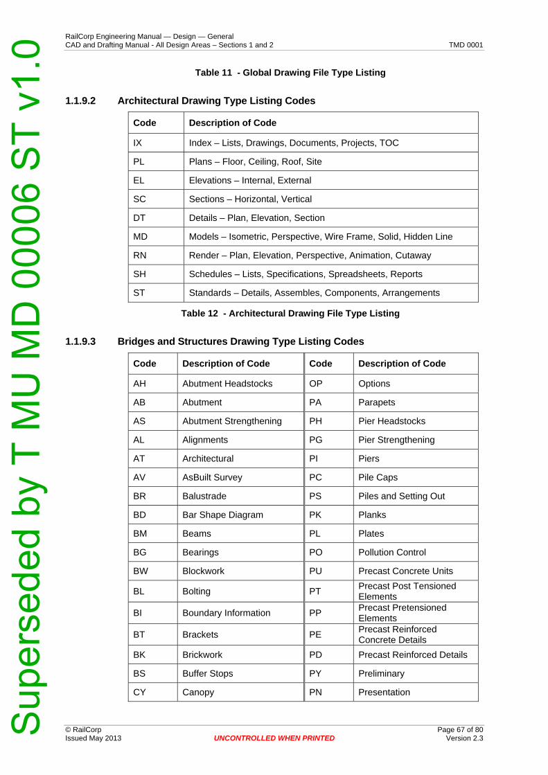
RailCorp Engineering Manual — Design — General CAD and Drafting Manual - All Design Areas – Sections 1 and 2 TMD 0001
© RailCorp Page 67 of 80 Issued May 2013 UNCONTROLLED WHEN PRINTED Version 2.3
Table 11 - Global Drawing File Type Listing
1.1.9.2 Architectural Drawing Type Listing Codes
Code Description of Code
IX Index – Lists, Drawings, Documents, Projects, TOC
PL Plans – Floor, Ceiling, Roof, Site
EL Elevations – Internal, External
SC Sections – Horizontal, Vertical
DT Details – Plan, Elevation, Section
MD Models – Isometric, Perspective, Wire Frame, Solid, Hidden Line
RN Render – Plan, Elevation, Perspective, Animation, Cutaway
SH Schedules – Lists, Specifications, Spreadsheets, Reports
ST Standards – Details, Assembles, Components, Arrangements
Table 12 - Architectural Drawing File Type Listing
1.1.9.3 Bridges and Structures Drawing Type Listing Codes
Code Description of Code Code Description of Code
AH Abutment Headstocks OP Options
AB Abutment PA Parapets
AS Abutment Strengthening PH Pier Headstocks
AL Alignments PG Pier Strengthening
AT Architectural PI Piers
AV AsBuilt Survey PC Pile Caps
BR Balustrade PS Piles and Setting Out
BD Bar Shape Diagram PK Planks
BM Beams PL Plates
BG Bearings PO Pollution Control
BW Blockwork PU Precast Concrete Units
BL Bolting PT Precast Post Tensioned Elements
BI Boundary Information PP Precast Pretensioned Elements
BT Brackets PE Precast Reinforced Concrete Details
BK Brickwork PD Precast Reinforced Details
BS Buffer Stops PY Preliminary
CY Canopy PN Presentation
Sup
erse
ded
by T
MU
MD
000
06 S
T v1
.0

RailCorp Engineering Manual — Design — General CAD and Drafting Manual - All Design Areas – Sections 1 and 2 TMD 0001
© RailCorp Page 68 of 80 Issued May 2013 UNCONTROLLED WHEN PRINTED Version 2.3
Code Description of Code Code Description of Code
CW Civil Works PR Proposal
CF Cladding and Flashing Details
RM Ramp
CP Column Protection RN Reconstruction
CL Columns RE Regrading
CN Concept Design RC Reinforced Concrete Details
CT Concrete RI Reinforcement Details
CC Concrete Details RL Remedial Work
CQ Construction Sequence RV Renovation
CG Coping RP Repairs
CS Cover Sheet RW Retaining Walls
CD Crane Details RD Roadway Details
CB Crash Beams RF Roof Details
XS Cross Section SS Safety Screens
CE Cycleway SC Scope of Works
DA Dead Man Anchoring SE Sections
DK Deck SP Service Parts
DM Demolition SR Services
DT Details SO Setting Out
DG Drainage SN Signal Structure
DL Drainage Layouts SB Sill Beam
DP Drainage Pits SI Site Plan
EW Earth Works SK Sketches
EL Electrical Layout ST Stairs
EV Elevation SD Standard Details
EX Existing DW Standard Drawings
ET Extension SW Steelwork
FS Feeder Structue Steelwork Details
FE Fencing SL Stools
FD Footing Details SG Strengthening Details
FO Footings SD Structure Diagrams
GA General Arrangements SQ Suggested Construction Sequence
GI General Information SV Survey
Sup
erse
ded
by T
MU
MD
000
06 S
T v1
.0

RailCorp Engineering Manual — Design — General CAD and Drafting Manual - All Design Areas – Sections 1 and 2 TMD 0001
© RailCorp Page 69 of 80 Issued May 2013 UNCONTROLLED WHEN PRINTED Version 2.3
Code Description of Code Code Description of Code
GL General Layout SA Switch Area
GD Girders SF Switch Frame
GR Grading TW Temporary Works
HS Headstock TD Timber Details
HP High Level Platforms TI Title Page
HD Hoarding TR Track Drainage
IP Inspection Pits TS Track Slabs
LD Ladders TB Traffic Barrier
LO Layout TM Traffic Management
MS Main Span UG Upgrading
MP Marking Plan VL Ventilation
MA Masonry Details WK Walkways
MS Miscellaneous WA Wall
MO Modifications WP Warning Portal
NO Notes WG Waterproofing
Table 13 - Bridges and Structures Drawing File Type Listing
1.1.9.4 Electrical Drawing Type Listing Codes
Code Description of Code
CF Cable Fitting and Arrangement Drawings
CR Cable Route Plans
BA ROW Bridge Arrangement and Bonding
XS ROW Cross Sections
FA ROW Feeding Arrangement Drawings
FI ROW Fitting and Arrangement Drawings
LO ROW Layout Drawings (Construction and As-built)
OA ROW Overlap Arrangement Drawings
PR ROW Profiles
TD ROW Tension Length Diagrams
CN Schematic Diagrams AC/DC Connection
DB Schematic Diagrams AC/DC Distribution Boards
DL Schematic Diagrams AC/DC Distribution Board Location
EI Schematic Diagrams Equipment Interconnection
Sup
erse
ded
by T
MU
MD
000
06 S
T v1
.0
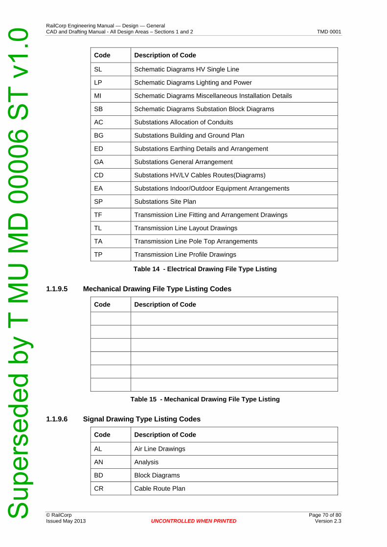
RailCorp Engineering Manual — Design — General CAD and Drafting Manual - All Design Areas – Sections 1 and 2 TMD 0001
© RailCorp Page 70 of 80 Issued May 2013 UNCONTROLLED WHEN PRINTED Version 2.3
Code Description of Code
SL Schematic Diagrams HV Single Line
LP Schematic Diagrams Lighting and Power
MI Schematic Diagrams Miscellaneous Installation Details
SB Schematic Diagrams Substation Block Diagrams
AC Substations Allocation of Conduits
BG Substations Building and Ground Plan
ED Substations Earthing Details and Arrangement
GA Substations General Arrangement
CD Substations HV/LV Cables Routes(Diagrams)
EA Substations Indoor/Outdoor Equipment Arrangements
SP Substations Site Plan
TF Transmission Line Fitting and Arrangement Drawings
TL Transmission Line Layout Drawings
TA Transmission Line Pole Top Arrangements
TP Transmission Line Profile Drawings
Table 14 - Electrical Drawing File Type Listing
1.1.9.5 Mechanical Drawing File Type Listing Codes
Code Description of Code
Table 15 - Mechanical Drawing File Type Listing
1.1.9.6 Signal Drawing Type Listing Codes
Code Description of Code
AL Air Line Drawings
AN Analysis
BD Block Diagrams
CR Cable Route Plan
Sup
erse
ded
by T
MU
MD
000
06 S
T v1
.0
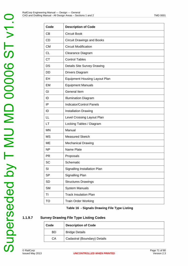
RailCorp Engineering Manual — Design — General CAD and Drafting Manual - All Design Areas – Sections 1 and 2 TMD 0001
© RailCorp Page 71 of 80 Issued May 2013 UNCONTROLLED WHEN PRINTED Version 2.3
Code Description of Code
CB Circuit Book
CD Circuit Drawings and Books
CM Circuit Modification
CL Clearance Diagram
CT Control Tables
DS Details Site Survey Drawing
DD Drivers Diagram
EH Equipment Housing Layout Plan
EM Equipment Manuals
GI General Item
ID Illumination Diagram
IP Indicator/Control Panels
ID Installation Drawing
LL Level Crossing Layout Plan
LT Locking Tables / Diagram
MN Manual
MS Measured Sketch
ME Mechanical Drawing
NP Name Plate
PR Proposals
SC Schematic
SI Signalling Installation Plan
SP Signalling Plan
SD Structures Drawings
SM System Manuals
TI Track Insulation Plan
TO Train Order Working
Table 16 - Signals Drawing File Type Listing
1.1.9.7 Survey Drawing File Type Listing Codes
Code Description of Code
BD Bridge Details
CA Cadastral (Boundary) Details
Sup
erse
ded
by T
MU
MD
000
06 S
T v1
.0

RailCorp Engineering Manual — Design — General CAD and Drafting Manual - All Design Areas – Sections 1 and 2 TMD 0001
© RailCorp Page 72 of 80 Issued May 2013 UNCONTROLLED WHEN PRINTED Version 2.3
Code Description of Code
DP Deposited Plans
DS Detail Survey
SK Sketches
XS Cross Section
Table 17 - Survey Drawing File Type Listing
1.1.9.8 Track Drawing Type Listing Codes
Code Description of Code
BI Ballast Depth Investigations
CR Check Rail Details
CI Clearance Investigation
CG Computer Illustrations and Graphics
CX Concrete Crossover Tie Details
CL Concrete Crossover Tie Layout and Details
CP Concrete Crossover Tie Pad Details
CS Concrete Crossover Tie Setting Out Details
CE Concrete End Infill Tie Layout and Details
CD Concrete Tie Details
TL Concrete Turnout Tie Layout and Details
TT Concrete Turnout Tie Pad Details
TR Concrete Turnout Tie Resilient Pad Details
XS Cross Sections
MA Detail Mapping
DS Detail Survey
DG Diagrams
DC Double Clip Washer and Pad Details
DD Drainage Design
GC General Arrangement – Concrete Details
GS General Arrangement – Steelwork Details
GA General Layout
GR Grading
HV Horizontal Vertical and Control
HA Horizontal Alignment
Sup
erse
ded
by T
MU
MD
000
06 S
T v1
.0

RailCorp Engineering Manual — Design — General CAD and Drafting Manual - All Design Areas – Sections 1 and 2 TMD 0001
© RailCorp Page 73 of 80 Issued May 2013 UNCONTROLLED WHEN PRINTED Version 2.3
Code Description of Code
ID Illustrative Drawing
KX K-Crossing Details
LO Layout Details
LX Level Crossing Design
MS Miscellaneous
PC Platform Clearance Investigations
PR Preliminary
SW Scope of Works
SO Setting Out Details
SL Site Locality Diagrams
SP Site Preparation Plans
SB Special Baseplate Details
SD Standard Drawing
SR Stock Rail Details
SW Switch Details
TP Timber and Platting
TD Timber and Platting Details
TB Track Books
TO Turnout Details
VX V-Crossing Details
VA Vertical Alignment
Table 18 - Track Drawing File Type Listing
1.1.10 Part E – CAD Element Abbreviations (Table 19)
Code Description Code Description
240V 240 Voltage LVOL Low Voltage
ABUT Abutment MAJR Major
ALUM Aluminium MARK Mark
ANCR Anchor MASN Masonry
APPL Appliance MECH Mechanical
AUXL Auxiliary META Metal
AXIS Axis MHOL ManHole
BALS Ballast MINR Minor
Sup
erse
ded
by T
MU
MD
000
06 S
T v1
.0

RailCorp Engineering Manual — Design — General CAD and Drafting Manual - All Design Areas – Sections 1 and 2 TMD 0001
© RailCorp Page 74 of 80 Issued May 2013 UNCONTROLLED WHEN PRINTED Version 2.3
Code Description Code Description
BATH Bathroom MISC Miscellaneous
BAYL Bay Length (Electrical) MOBE Mobile
BEAM Beam MRKG Markings
BENT Bent MRKS Marks
BITM Bitumen NGAS Natural Gas
BLDG Building NODE Node (Point)
BLOW Blow Out (Electrical) NOTE Note
BNDY Boundary NRTH North
BOOM Boom (Ohw Structures) NUMB Number
BORE Borings OHWA Over Head Wiring Anchor
BUBB Bubble OHWC Over Head Wiring Conductor
BUSH Bush OHWR Over Head Wiring Registration
CABL Cable OHWS Over Head Wiring Structure
CAIR Compressed Air OPEN Open
CDST Cadastral OTLN Outline
CEIL Ceiling OUTD Outdoor
CHCK Check OVER Overall
CLAD Cladding OVHD Overhead
CNST Construction PAIN Paint
CNTJ Control Joint PAVE Paveing
CNTR Centre Line PEOP People
CNTY County PIPE Pipe
COGO Coordinate Geometry PITS Pits
COLD Cold PLAS Plaster
COLM Column PLAT Platform
COMM Commercial PLNT Plant
COMS Communication PLTS Plates
CONC Concrete POST Post
COPG Coping POWR Power
CORP Corporation PRKG Parking
CTRL Control PROF Profile
CULV Culvert PROV Province
CUTT Cutting PRSH Parish
Sup
erse
ded
by T
MU
MD
000
06 S
T v1
.0

RailCorp Engineering Manual — Design — General CAD and Drafting Manual - All Design Areas – Sections 1 and 2 TMD 0001
© RailCorp Page 75 of 80 Issued May 2013 UNCONTROLLED WHEN PRINTED Version 2.3
Code Description Code Description
DECK Deck RAIL Rail
DEMO Demolition RALG Railings
DETL Detail RAMP Ramp
DGRM Diagram RATA RTA
DIMS Dimensions RIVR River
DISP Display ROAD Road
DOMS Domestic ROOF Roof
DOOR Door RSVR Reserve
DRAN Drain RTWL Retaining Wall
DRFT Drafting SANI Sanitary
DRIV Driveway SBCK Setback
DUCT Conduit (Plastic Containers) SCHD Schedule
EDGE Edging SCHM Schematic
ELEC Electrical SECU Security
EMBK Embankment SERV Services
EMER Emergency SETO Set out
EOHW Electrical OHW SEWR Sewer
EQIP Equipment SHEET Sheet Indicator
EQPT Equipment SIGL Signals
ESCL Escalator SIGN Sign
ESMT Easement SITE Site
EWRK Earthworks SLAB Slab
EXST Existing SLEE Track Sleeper
EXTR Extract SLPR Sleeper
FACE Face SPIL Stock Pile
FEAT Feature SPRI Sprinkler
FENC Fence SRA State Rail Authority
FILL Fill STAR Stairs
FITT Fittings STEP Steps
FIXD Fixed STGR Stagger
FIXT Fixture STNA Stationing
FLOR Floor STOR Storage
FOOT Foot STRC Structure
Sup
erse
ded
by T
MU
MD
000
06 S
T v1
.0

RailCorp Engineering Manual — Design — General CAD and Drafting Manual - All Design Areas – Sections 1 and 2 TMD 0001
© RailCorp Page 76 of 80 Issued May 2013 UNCONTROLLED WHEN PRINTED Version 2.3
Code Description Code Description
FPTH Footpath STRE Street
FRAM Frame STRM Stormwater
FRMT Formation SUBD Subdivision
FTGS Footings SUBW Subway
FUEL Fuel SUPP Supply
FURN Furniture SURV Survey
GENL General SYMB Symbols
GLAS Glass SYMG Symbology
GLAZ Glazing TABL Table
GRAF Graphics TANK Tank
GRAV Gravel TEXT Text
GRDN Garden TILE Tile
GRDR Girder TRAK Track
GRID Grid TRAN Transit
GRND Ground TRAV Travelator
GRVL Gravel TREE Tree
GUTT Gutter TRES Trestle
HEAD Head TRGH Troughing
HIDD Hidden TRLA Transmission Line Anchor
HOT Hot TRLC Transmission Line Conductor
HRAL Handrail TRLR Transmission Line Registration
HTCH Hatch TRLS Transmission Line Structure
HVOL High Voltage TRNO Turnout
HYDR Hydraulic TTLE Title
INDR Indoor TUNL Tunnel
INDU Industrial TURF Turf
INSL Insulators UNDR Under
INST Instruments UNID Unidentified
ITRN Internal UPVD Unpaved
JOIN Joinery VEGE Vegetation
KERB Kerb VEHC Vehicle
KILM Kilometrage VENT Ventilation
KMAJ Kilometrage Adjustment VERS Versine
Sup
erse
ded
by T
MU
MD
000
06 S
T v1
.0
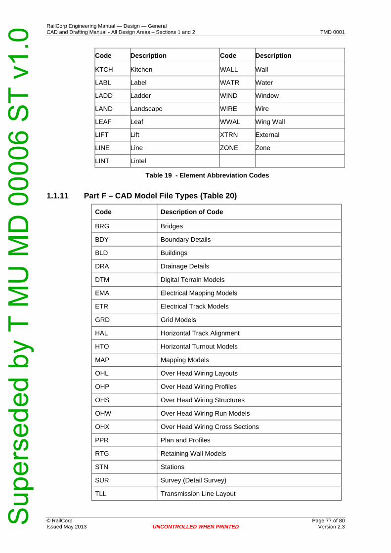
RailCorp Engineering Manual — Design — General CAD and Drafting Manual - All Design Areas – Sections 1 and 2 TMD 0001
© RailCorp Page 77 of 80 Issued May 2013 UNCONTROLLED WHEN PRINTED Version 2.3
Code Description Code Description
KTCH Kitchen WALL Wall
LABL Label WATR Water
LADD Ladder WIND Window
LAND Landscape WIRE Wire
LEAF Leaf WWAL Wing Wall
LIFT Lift XTRN External
LINE Line ZONE Zone
LINT Lintel
Table 19 - Element Abbreviation Codes
1.1.11 Part F – CAD Model File Types (Table 20)
Code Description of Code
BRG Bridges
BDY Boundary Details
BLD Buildings
DRA Drainage Details
DTM Digital Terrain Models
EMA Electrical Mapping Models
ETR Electrical Track Models
GRD Grid Models
HAL Horizontal Track Alignment
HTO Horizontal Turnout Models
MAP Mapping Models
OHL Over Head Wiring Layouts
OHP Over Head Wiring Profiles
OHS Over Head Wiring Structures
OHW Over Head Wiring Run Models
OHX Over Head Wiring Cross Sections
PPR Plan and Profiles
RTG Retaining Wall Models
STN Stations
SUR Survey (Detail Survey)
TLL Transmission Line Layout
Sup
erse
ded
by T
MU
MD
000
06 S
T v1
.0

RailCorp Engineering Manual — Design — General CAD and Drafting Manual - All Design Areas – Sections 1 and 2 TMD 0001
© RailCorp Page 78 of 80 Issued May 2013 UNCONTROLLED WHEN PRINTED Version 2.3
Code Description of Code
TLP Transmission Line Profile
TLX Transmission Line Cross Sections
TRL Track Layout Model (Composite)
TRP Track Profile Model
TRX Track Cross Section Model
TUN Tunnels
UTL Utility Detail Layout Model
VAL Vertical Track Alignment Profile
XSC Cross Sections (General)
Table 20 - CAD Model File Type Listing
1.1.12 Part G – Track Corridor Line Codes (Table 21)
Code Description of Code OLD Unix Codes
H01 Homebush Loop
I00 Illawarra Line 500
I10 Coniston - Port Kembla 501
I20 Sutherland - Cronulla 008
I21 Loftus - Royal National Park 504
M00 Main Suburban 003
M01 City Underground 000
M13 Clyde - Carlingford 006
M17 Blacktown - Richmond 009
M23 Eastern Suburbs 001
M24 Bankstown 005
M25 Tempe - Glenfield 007
M26 New Southern Railway
M29 Waverton - Lavender Bay 016
M45 Chullora Branch
M50 Botany Line 013
M52 Metropolitan Goods 012
M58 Rozelle 011
M66 Chullora Jct - Sefton Jct 017
M71 Flemington Jct
Sup
erse
ded
by T
MU
MD
000
06 S
T v1
.0

RailCorp Engineering Manual — Design — General CAD and Drafting Manual - All Design Areas – Sections 1 and 2 TMD 0001
© RailCorp Page 79 of 80 Issued May 2013 UNCONTROLLED WHEN PRINTED Version 2.3
Code Description of Code OLD Unix Codes
M73 Rosehill - Sandown 015
M78 Olympic Park Loop
N00 Main North 200
N30 North Shore 002
N33 Woodville Jct - Newcastle
S00 Main South 400
W00 Main West 300
W40 St Marys - Ropes Creek 010
Table 21 - Track Corridor Line Code Listing
1.1.13 Part H – DTM Surface Types (Table 22)
Code Description of Code
BAL Ballast Profile Surface
BDG Bridge Surfaces
CAT OHW Catenary Surface
CON OHW Contact Surface
DTM Digital Terrain Model Surface (Combined)
EWK Earthworks Surface
FEA Feature (Non-Contour able) Surface
FRM Formation Surface
NAT Natural (Contour able) Surface
OBD Overbridge Deck (Top) Surface
OBU Overbridge Underside Surface
PFM Platform Surface
RDW Roadway Surface
RLH Rail Surface High Rail Level
RLL Rail Surface Low Rail Level
RLM Rail Surface Mean Rail Level
SBT Sub Surface (Existing) Top Ballast Layer
SBB Sub Surface (Existing) Bottom Ballast Layer
SEW Sub Surface (Existing) Earthworks Layer
UBD Underbridge Deck (Top) Surface
UBU Underbridge Underside Surface
Sup
erse
ded
by T
MU
MD
000
06 S
T v1
.0

RailCorp Engineering Manual — Design — General CAD and Drafting Manual - All Design Areas – Sections 1 and 2 TMD 0001
© RailCorp Page 80 of 80 Issued May 2013 UNCONTROLLED WHEN PRINTED V 2.3ersion
Table 22 - CAD DTM Surface File Types Listing
1.1.14 Part I – Geometry File Types (Table 23)
Code Description of Code
ALG Track Alignment Geometry
HAL Horizontal Track Alignment
VAL Vertical Track Alignment
EAL Super Elevation Alignment
RDF Rail Running Face Down Alignment
RUF Rail Running Face Up Alignment
RDC Rail Centreline Down Alignment
RUC Rail Centreline Up Alignment
HAX Horizontal Track Cross Over Alignment
VAX Vertical Track Cross Over Alignment
EAX Super Elevation Cross Over Alignment
BYG Boundary Geometry
HBY Horizontal Boundary Alignment
OHW Overhead Wiring Geometry
HOH Horizontal Overhead Wiring Alignment
VOH Vertical Overhead Wiring Alignment
RDG Roadway Alignment Geometry
HRD Horizontal Roadway Alignment
VRD Vertical Roadway Alignment
TLG Transmission Line Geometry
HTL Horizontal Transmission Line Alignment
VTL Vertical Transmission Line Alignment
CTO Horizontal Conventional Turnout
TTO Horizontal Tangential Turnout
Table 23 - Geometry File Types Listing
Sup
erse
ded
by T
MU
MD
000
06 S
T v1
.0