TECHNICAL NOTE NASA TN 0-8085
43
NASA 00 0 c? d z c 4 m 4 z TECHNICAL NOTE NASA - e - TN 0-8085 d -I m 0 I r s n m z L LOAN COPY: RETURN TO /;-zWi TECHNICAL LIBRARY KIRTLAND Af'& w. FLUTTER ANALYSIS OF TWO PARALLEL ELASTICALLY COUPLED FLAT PLATES I 1 Charles P. Shore I / / Luizgley Reseurch Center Hanzptol2, Va, 23 665 NATIONAL AERONAUTICS AND SPACE ADMINISTRATION WASHINGTON, D. C. DECEMBER 1975 I I' i II
Transcript of TECHNICAL NOTE NASA TN 0-8085

N A S A
00 0 c?d z c
4 m 4 z
TECHNICAL NOTE NASA e- TN 0-8085 d -I m 0I r
s n m zL
LOAN COPY: RETURN TO / ; -zWi TECHNICAL LIBRARY
KIRTLAND Af'& w.
FLUTTER ANALYSIS OF TWO PARALLEL ELASTICALLY COUPLED FLAT PLATES
I 1
Charles P. Shore I / /
Luizgley Reseurch Center Hanzptol2, Va, 23 665
N A T I O N A L A E R O N A U T I C S AND S P A C E ADMINISTRATION WASHINGTON, D. C. D E C E M B E R 1975
I I'
iII

TECH LIBRARY KAFB. NM
- .
1. Report No. 2. Government Accession No.
NASA TN D-8085 ! 4. Title and Subtitle
COUPLED FLAT PLATES
9. Performing Organization Name and Address
NASA Langley Research Center Hampton, Va. 23665
2. Sponsoring Agency Name and Address
5. Supplementary Notes
.-6. Abstract
II 5. Report Date
6. Performing Organization Code
10. Work Unit No.
505-02- 12-01 11. Contract or Grant No.
13. Type of Report and Period Covered
Technical Note
Flutter of two parallel elastically coupled flat plates is investigated analytically. A closed-form solution including both aerodynamic and s t ructural damping is presented for flutter of flat orthotropic plates coupled by an elastic medium. Both plates are simply supported along the side edges but are supported by deflectional, rotational, and torsional springs of arbi t rary stiffness a t the leading and trailing edges. Two-dimensional quasi-steady aerodynamics is utilized in the solution. Since the large number of variables p re s ent in the problem precludes extensive parametr ic studies, resul ts are presented to indicate the basic flutter character is t ics of coupled two-plate systems and to assess the validity of previously published modal solutions for s imilar problems.
7. Key Words (Suggested by Author(s)) 18. Distribution Statement
Panel flutter Unclassified - Unlimited Buckling Damping Elastic coupling Vibration Subject Category 39
.
19. Security Classif. (of this report) 20. Security Classif.'(of this page) 21. No. of Pages 22. Price'
Unclassified . . I Unclassified I . .
$3.75
For sale by the National Technical Information Service, Springfield, Virginia 22161
FLUTTER ANALYSIS O F TWO PARALLEL ELASTICALLY
COUPLED FLAT PLATES
Charles P. Shore Langley Research Center
SUMMARY
Flutter of two parallel elastically coupled flat plates is investigated analytically. A closed-form solution including both aerodynamic and structural damping is presented for flutter of flat orthotropic plates coupled by an elastic medium. Both plates are simply supported along the side edges but are supported by deflectional, rotational, and torsional springs of arbi t rary st iffness at the leading and trailing edges. Two-dimensional quasi-steady aerodynamics is utilized in the solution. Since the large number of variables present in the problem precludes extensive parametric studies, results are presented to indicate the basic flutter characterist ics of coupled two-plate systems and to a s ses s the validity of previously published modal solutions for similar problems.
INTRODUCTION
Flutter of two simply supported parallel isotropic plates connected by an elastic medium has been investigated previously in connection with micrometeroid bumpers which are attached to a primary structural skin by a light soft filler material. Although intended primarily as a protective device in space, such configurations must withstand severe aerodynamic loads during launch. In reference 1a two-mode Galerkin solution to the coupled fourth-order differential equations describing motion of the two plates was obtained. The simple Ackeret expression for the lateral loading due to air pressure was used in the analysis. In reference 2 a two-mode flutter solution which used piston theory aerodynamics to incorporate aerodynamic damping effects was obtained for the coupled-plate problem. In addition a semiexact procedure and a finite-difference formulation were outlined; however, the only results presented were from the two-mode solution. Results presented in references 1 and 2 indicate that the elastic coupling medium can have significant effects on the flutter response of the two-plate system. In fact, depending on the magnitude of inplane loads acting on the plates and the spring stiffness of the elastic coupling medium, the two-plate system can become unstable at much lower dynamic pressu res than either of the two plates alone.
More recently several thermal protection systems which employ exposed surfaces coupled to primary load carrying s t ructures by flexible insulation and/or strain-isolator
n
systems have been proposed for space shuttle and hypersonic cruise vehicles. The flutter characteristics of reusable surface insulation (RSI) panels coupled to a primary structure by a flexible strain isolator have been studied in reference 3. The analysis utilizes plate modes for the simply supported primary structure and free-free beam modes for the RSI panels. Dynamic response of the coupled system was obtained by application of the Rayleigh-Ritz technique. Results presented in reference 3 indicate that the presence of the RSI panels has a highly stabilizing effect on the flutter response of the primary structure. The main cause of the increased flutter stability of the primary structure was attributed to the segmented mode shapes of the RSI panels which govern the interaction of the aerodynamic forces and the deflections of the primary structure. Finally, the typical severely destabilizing influence of midplane compressive loads on single isotropic panels was not always observed for the coupled system, and the buckling value of the mid-plane loading for the primary structure was found to be increased significantly by the RSI/strain-isolator system.
In many instances the exposed surfaces of typical thermal protection systems consis t of highly orthotropic panels with arbitrary flexible supports at the boundaries. (See ref. 4.) Thus, the present report extends the previous solutions to a more general configuration consisting of two parallel orthotropic plates connected by an elastic medium and supported at the leading and trailing edges on springs of arbitrary stiffness. Piston theory aerodynamics is employed to obtain the lateral loading due to air pressure over the exposed plate, and taking the side edges of the plates to be simply supported allows a closed-form solution (i.e., nonmodal) to the governing partial differential equations. Results from the analysis a r e compared with results from references 1to 3 , and a general flutter boundary for two identical simply supported coupled plates is presented for a single value of the elastic spring stiffness of the connecting medium. Specific examples are also presented to indicate the applicability of the solution and to indicate some effects of structural damping and inplane loading on the flutter of elastically coupled parallel plates. Additionally, the influence on flutter of single plates with unequal support springs at the leading and trailing edges is briefly discussed.
SYMBOLS
Dimensional quantities are presented both in the International System of Units (SI) and in the U.S. Customary Units. Measurements were made in U.S. Customary Units.
Ai deflection shape coefficients
-A parameter defined by equation (16)
a plate length
2
-B
b
parameter defined by equation (17)
plate width
free-stream speed of sound
plate bending stiffness in x-direction
plate bending stiffness in y-direction
plate twisting stiffness
plate stiffness coefficients defined by equation (7)
Young's modulus
complex deflectional, torsional, and rotational support spring coefficients defined by equation (11)
complex coefficients defined by equation (8)
aerodynamic damping coefficient, pc/yuwr ,u
deflectional, torsional, and rotational support spring structural damping coefficients
elastic coupling-medium structural damping coefficient
plate structural damping coefficients
moment of inertia
imaginary unit,
complex spring stiffness of elastic coupling medium
spring stiffness of elastic coupling medium in compression
deflectional, torsional, and rotational spring stiffnesses
3

I l l I 1 I
aerodynamic loading term
Mach number
m number of half-waves in streamwise direction
NX inplane loading in x-direction, positive i n compression
NY inplane loading in y-direction, positive in compression
n number of tiles
Pi roots to equation (22)
q free-stream dynamic pressure
RX nondimensional inplane loading parameter in x-direction, Nxb2/.2D1
Rx ,c r buckling load with no airflow
RY nondimensional inplane loading parameter in y-direction, Nyb”/”D17~
S coupling-medium spring parameter defined by equations (18)
t time
V f ree-st ream velocity
W lateral deflection
X deflection shape in x-direction
Cartesian coordinates
coefficients defined by equation (A5)
P compressibility factor, {z Y plate mass per unit a r e a
4

c complex frequency coefficient, $I + i w
x dynamic -pressure parameter, 2qaypD1,u
Px+y Poisson's ratio i n x-direction and y-direction, respectively
P free-stream air density
$I real par t of complex frequency exponential coefficient
[521 boundary condition matrix
W circular frequency
wr reference frequency, see equations (18)
Subscripts:
L lower plate
le leading edge
max maximum
te trailing edge
U upper plate
Two te rms , one above the other, within braces { } occur in the equations of this report. This notation means that two equations may be obtained by substituting first the upper and then the lower term. For example, equation (4b)
D
- PX,UI-lY,U(-2 at x - 0x7u
means that
at x = o '
5

- = o
and
awU at x = a + kr,te,U ax
ANALYSIS
The configuration to be analyzed is shown in figure 1and consists of an upper orthotropic plate exposed to the airflow coupled, by a linearly elastic medium, to a lower orthotropic plate. The coupling medium behaves like a Winkler foundation in that an applied force causes deflection only at the point of application of the force. Both plates are simply supported along the side edges but are supported by deflectional, rotational, and torsional springs of arbi t rary stiffness at the leading and trailing edges. Each plate may also have different material properties and inplane loadings.
Differential Equations and Boundary Conditions
The appropriate small-deflection equilibrium equations for the two orthotropic plates in the presence of inplane tensile o r compressive loads may be written in the following form (ref. 1):
Upper plate
2 82WU 2 a wu a wu + k(wu - wL) = I(x,y,t)
+ Nx,u2+ Ny,u -+ Yu -ax ,Y2 a t2
Lower plate
6
-- - -
The subscripts U and L refer to the upper and lower plates, respectively; for each plate the bending stiffnesses in the x- and y-directions a r e denoted by Dx and Dy, respectively; Dxy denotes the plate twisting stiffness, y is the plate mass per unit area, and k denotes the spring stiffness of the elastic coupling medium in compression. The lateral loading induced by supersonic flow over the upper plate is assumed to be given by two-dimensional quasi-steady aerodynamic theory, so that
awUZ(x,y,t) = 2q awU PC -P ax a t
1where q = -pV2 is the free-s t ream dynamic pressure and p = \JM2 - 1 is the compres2
sibility factor. The first t e rm on the right side of equation (3) corresponds to a static loading and the second term is an aerodynamic damping term. References 5 and 6 have shown that for M > 1.6 and a/b from 0 to 10, use of two-dimensional aerodynamic theory yields flutter results in good agreement with those predicted by more exact aerodynamic theory.
According to reference 7 the boundary conditions may be written as follows:
Upper plate
7

Lower plate Replace subscript U by L i n equations (4a) and (4b); equation (4c) becomes
The frequency-independent, linear, hysteretic formulation of structural damping used in reference 6 is employed in the present analysis by modifying all the t e rms in equations (l), (2), and (4) containing plate bending stiffnesses o r spring stiffnesses by an appropriate (1+ ig) factor for simple harmonic motion. This procedure is equivalent to assuming orthotropic structural damping properties as well as orthotropic stiffness proper t ies for both plates and permits arbitrary levels of structural damping to be considered for each of the leading- and trailing-edge support springs as well as for the elastic coupling medium.
Solution
With introduction of the generalized aerodynamic loading and of structural damping and with division by the appropriate
the upper and lower plates, equations (1)and (2) become
Upper plate
4 2 a wu + Nx,u a wu
ax ay4 D i , ~ax2
a2wU YU a2wU K D+k-+-- + -(Wu - W L ) + Dl,u- (5)
2 D i , ~at2 i,u
a

- - .. - ...... . . . .
Lower plate
2 2 N a w Y L a wL + --(WLK+J&L+-- - wu) = 0
ay2 D i , ~Di , ~ at2 1,L
where the plate stiffness coefficients are defined as
and the damping factors are defined as
Gx = 1+ igx Gxy = 1 + igxy GY -- 1 + igy K = k(l + igk) (8 )
Similarly the boundary conditions for the upper plate become
awU = 0 at x ={}ax
D1,u
D1,U -Gt,te,U
D1,U - ““I
a3wU X-- + G -+
ax ay2 x,u ax3
--
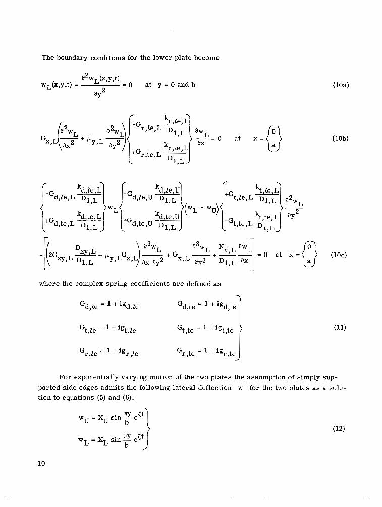
The boundary conditions for the lower plate become
a w L - 0 at + I - l Y J ax
= O a t x = (10c)
where the complex spring coefficients are defined as
Gd,le = + igd,Ze Gd,te = '+ igd,te 1 For exponentially varying motion of the two plates the assumption of simply sup
ported side edges admits the following lateral deflection w for the two plates as a solution to equations (5) and (6):
10

where X is the deflection shape in the x-direction and ( is of the form
Reference 8 has shown that for simple supports along the lateral edges there is no stiffness coupling between cross-s t ream modes. U s e of two-dimensional aerodynamic theory precludes any aerodynamic coupling of orthogonal cross-stream modes; thus, modes with a single half-wave in the cross-stream direction have the lowest natural f requencies and are used to determine the dynamic stability criterion (lowest value of X for which @ > 0) for the coupled-plate system under consideration.
Substitution of the expressions in equation (12) for wu and wL into equations (5) and (6) results i n the following two coupled fourth-order ordinary differential equations in Xu and XL:
Gx,uXC) + xuXG + AX; + gUXu - 7r4SUXL = 0
x ( 4 ) + ALX;: + BLXL - 714SLXU = 0 Gx,L L
where the primes denote derivatives with respect to x/a and where
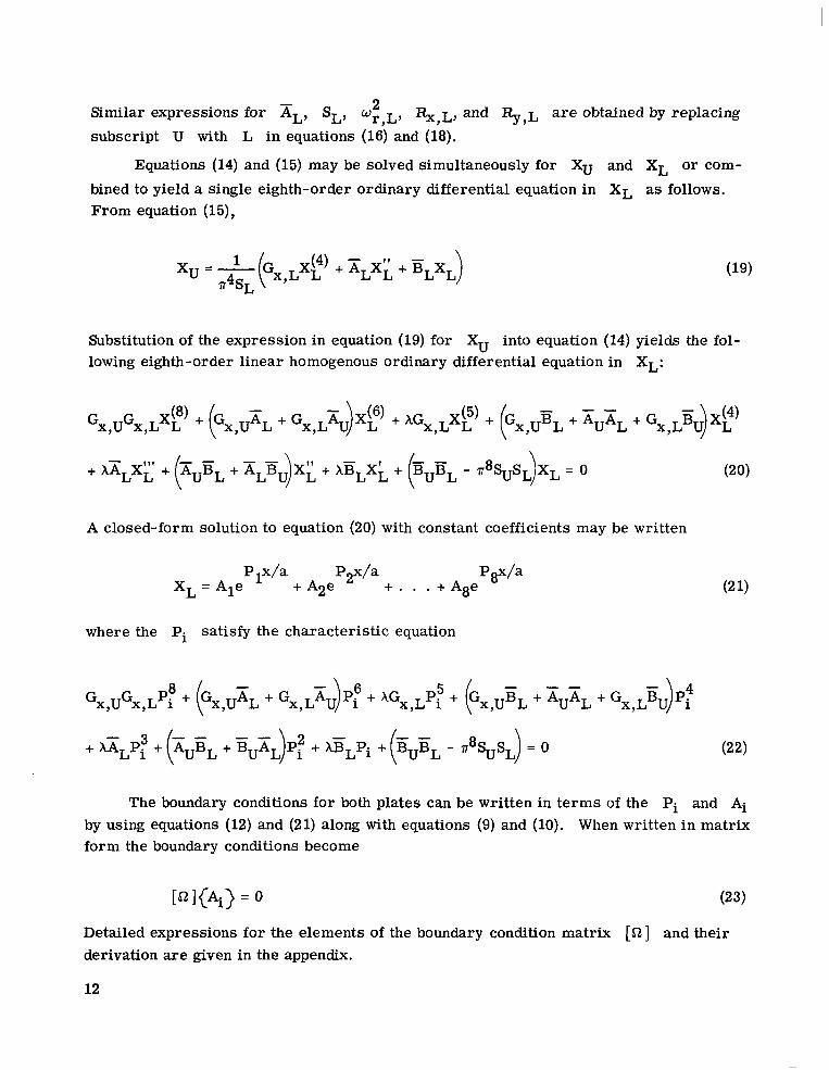
Similar expressions for xL, SL, w ~ , ~ ,2 %,L, and %,L are obtained by replacing subscript U with L i n equations (16) and (18).
Equations (14) and (15) may be solved simultaneously for XU and XL or com
bined to yield a single eighth-order ordinary differential equation in XL as follows. From equation (15),
xu = p(Gx,Lxp + XLX;: + ELXL11 = SL
Substitution of the expression in equation (19) for Xu into equation (14)yields the following eighth-order linear homogenous ordinary differential equation in XL:
A closed-form solution to equation (20) with constant coefficients may be written
where the Pi satisfy the characteristic equation
-+ XALPi + AUBL + - r8%SL) = 0r -
The boundary conditions for both plates can be written in t e rms of the Pi and Ai by using equations (12) and (21) along with equations (9) and (10). When written in matrix form the boundary conditions become
Detailed expressions for the elements of the boundary condition matrix [a]and their derivation are given in the appendix.
12
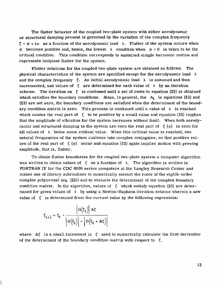
The flutter behavior of the coupled two-plate system with either aerodynamic o r structural damping present is governed by the variation of the complex frequency < = Q, + i w as a function of the aerodynamic load A. Flutter of the system occurs when Q, becomes positive and, hence, the lowest X condition when Q, = 0 is taken to be the critical condition. This condition corresponds to sustained simple harmonic motion and represents incipient flutter for the system.
Flutter solutions for the coupled two-plate system are obtained as follows. The physical characteristics of the system are specified except for the aerodynamic load X and the complex frequency c. An initial aerodynamic load X is assumed and then incremented, and values of 5 are determined for each value of X by an iteration scheme. The iteration on c is continued until a set of roots to equation (22)is obtained which satisfies the boundary conditions. Since, in general, the Ai in equations (21)and (23)are not zero, the boundary conditions are satisfied when the determinant of the bounda ry condition matrix is zero. This process is continued until a value of X is reached which causes the rea l part of 5 to be positive by a small value and equation (12)implies that the amplitude of vibration for the system increases without limit. When both aerodynamic and structural damping in the system are zero the rea l part of 5 (@) is zero for all values of X below some critical value. When this critical value is reached, two natural frequencies of the system coalesce into complex conjugates, so that positive V a l
ues of the real part of { (+) occur and equation (12)again implies motion with growing amplitude, that is, flutter.
To obtain flutter boundaries for the coupled two-plate system a computer algorithm was written to obtain values of c as a function of X. The algorithm is written in FORTRAN IV for the CDC 6000 se r i e s computers at the Langley Research Center and makes use of library subroutines to numerically extract the roots of the eighth-order complex polynomial (eq. (22)) and to evaluate the determinant of the complex boundary condition matrix. In the algorithm, values of which satisfy equation (23) a r e determined for given values of X by using a Newton-Raphson iteration scheme wherein a new value of 5 is determined from the current value by the following expression:
where A{ is a small increment in used to numerically calculate the f i rs t derivative of the determinant of the boundary condition matrix with respect to 5 .
13
RESULTS AND DISCUSSION
Because of the large number of variables involved, no attempt was made to conduct extensive parametric studies of the flutter behavior of coupled two-plate systems. However, results are presented to show that when aerodynamic and structural damping effects are ignored and the two plates are identical with respect to geometry, inplane loading, edge conditions, and material properties, flutter boundaries can be obtained in t e rms of the general parameters and as was done in references 8 and 9 for single plates. Some effects of structural damping on the flutter of coupled identical plates for a/b = 4 are also presented. In addition, results from the current analysis a r e compared with results from the modal solutions of references 1 and 2 to assess the validity of these solutions. Two thermal protection systems proposed for space shuttle which can be modeled as coupled two-plate systems a r e analyzed to determine their flutter characterist ics. For each system the stiffnesses of the upper and lower plates differ by 2 orders of magnitude. The plate with low stiffness is exposed to the flow in one system and in the other the plate with high stiffness is exposed to the flow. A discussion of the relative flutter behavior of the two systems is also presented. Finally, the influence on flutter of single plates of unequal support springs at the leading and trailing plate edges is discussed briefly.
Flutter Boundary for Identical Coupled Plates
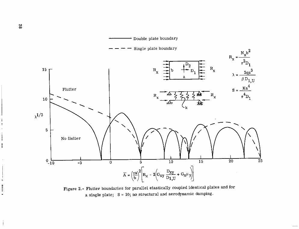
When aerodynamic and structural damping are neglected and when the two plates are identical with respect to geometry, inplane loading, and material properties, equations (16) and (17) indicate that the respective and parameters for the two plates a r e equal. For these conditions it is possible to obtain general flutter boundaries for the coupled system for specific stiffness values of the elastic coupling medium and specified boundary conditions. Such flutter boundaries a r e then applicable to a wide variety of panel configurations, material properties, and inplane loadings.
Although it is possible to generate solutions for various values of the spring s t i f f ness of the coupling medium and for various boundary conditions, only one such solution with both plates simply supported and a coupling-medium spring parameter of SU = SL = 10 (representative of a lightly coupled system) was obtained to illustrate the nature of such solutions. Figure 2 shows a comparison of the resulting flutter boundary for a coupled two-plate system with a similar boundary for a single plate. The boundaries are shown in terms of X1I3 as a function of A. The anomalous X = 0 flutter points occur whenever has a value that causes the two vibration modes which coalesce flutter to have equal natural frequencies for no airflow. For the coupled-plate system the larger number of X = 0 flutter points results from the fact that the coupled system has twice the number of natural vibration frequencies associated with a single plate.
14

Eight natural frequencies of the coupled system are shown in figure 3 in which the- -frequency parameter B is shown as a function of A. The solid curves correspond to vibration modes of the two plates which are in phase, the dashed curves correspond to vibration modes of the two plates which are 180° out of phase, and m denotes the number of half-waves in the s t ream direction. Shaded regions between any two curves indicate that those modes contiguous to the shaded regions on the plot coalesce to give the lowest value of X for flutter. As usual in panel flutter, adjacent odd and even modes coalesce for flutter. However, since the coupled-plate system has both in-phase and outof-phase vibration modes, many possibilities exist for coalescence of multiple pairs of modes which have nearly the same degree of frequency separation, and i t is not obvious which pair wil l give the lowest flutter value of A. Comparison of figures 2 and 3 indicates that the X = 0 flutter points coincide with crossings of frequencies which coalesce for flutter and that the multiplicity of these points results from the double set of frequencies.
Although variation of the coupling-medium spring parameter S is not expected to change the basic character of the flutter boundary for the two-plate system, such changes will influence the separation of the in-phase and out-of-phase natural frequencies for the system and hence the values at which the X = 0 flutter points occur. Reference 6 shows that inclusion of aerodynamic and structural damping in the theory can remove the X = 0 flutter points for single plates. Calculations were made to determine whether the same effects hold for a coupled two-plate system. However, since inclusion of damping precludes a flutter solution in t e rms of the general parameters and E,i t is necessary to pick a specific plate configuration. Thus, an a/b = 4 coupled-plate system is used to illustrate the effects of aerodynamic and structural damping on the flutter of coupled plates. Flutter boundaries for such a system with S u = SL = 10 are shown in figure 4 in which X1/3 is shown as a function of the inplane loading parameter R,. The dashed boundary is for no damping and the solid boundary is for structural damping coefficients g,, gxy, and gy of 0.01 in the plates and aerodynamic damping corresponding to sea level conditions. The aerodynamic damping is based on a 0.051-cm (0.02-in.) thick aluminum plate and sea level air properties and was calculated from the following equation from reference 6:
The damping has a strong smoothing effect on the flutter boundary and completely removes the X = 0 flutter points. Although on the basis of these a/b = 4 results, it appears that damping has a large stabilizing effect and removes the h = 0 flutter points for both one-and two-plate systems, such is not always the case. For example, reference 10 shows
15

I l l IIIII IIIIII I I l l 1
that structural damping is destabilizing for built-up plates with low a/b ratios (approximately 1). Limited results concerning such behavior are discussed in a subsequent section.
Comparison of Modal and Closed-Form Results
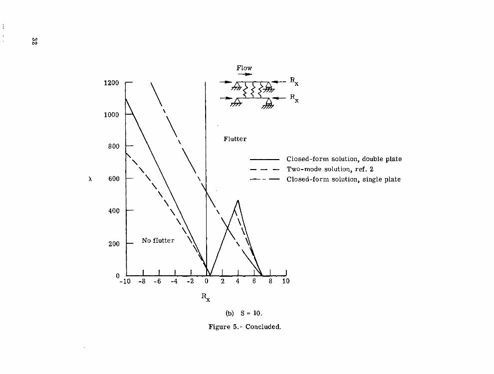
References 1 and 2 present resul ts from two-mode Galerkin solutions for a coupled two-plate system with a/b = 1, simple support boundary conditions, and a value of the coupling-medium spring parameter SU = SL = S = 20. Reference 2 also presents a flutter boundary for S = 10. In figure 5(a), results from both analyses are compared with closed-form results from the present analysis. Flutter boundaries for identical plates with identical inplane loading are shown i n t e rms of X as a function of the inplane loading parameter Rx. These results are for S = 20. Closed-form results a r e shown by the solid curve and modal results are shown by the dashed curve (ref. 1)and by the circular symbols (ref. 2). A closed-form boundary for a single plate is shown for reference. As mentioned in reference 2, for some as yet unexplained reason the two modal solutions from references 1 and 2 do not agree, although both employ the same representation of the mode shapes. The two-mode Galerkin solutions have the correct trends but tend to be unconservative for some values of Rx. Results for S = 10 are shown in figure 5(b) and again the two-mode solution has the correct trend, but i t shows a tendency toward conservatism in some regions particularly as Rx increases negatively. The results of figure 5 indicate that as S increases f rom 10 to 20, the f i rs t X = 0 flutter point shifts to a negative (tensile) value of Rx. As mentioned in reference 2, inclusion of aerodynamic damping will remove the anomalous X = 0 flutter point; but as indicated on figu re 5(a), the boundary continues to exhibit a large dip in the vicinity of R, = -7. Calculations from the closed-form solution showed the same trends, and when structural damping was included i n the calculations, no appreciable effect w a s found at the X = 0 flutter points; however, the structural damping was found to be destabilizing for other values of Rx. As mentioned previously, this destabilizing effect has been noted for single plates i n reference 10 and was not pursued further in the current investigation.
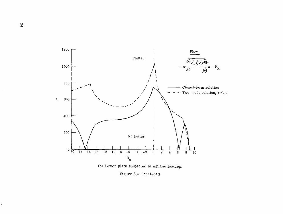
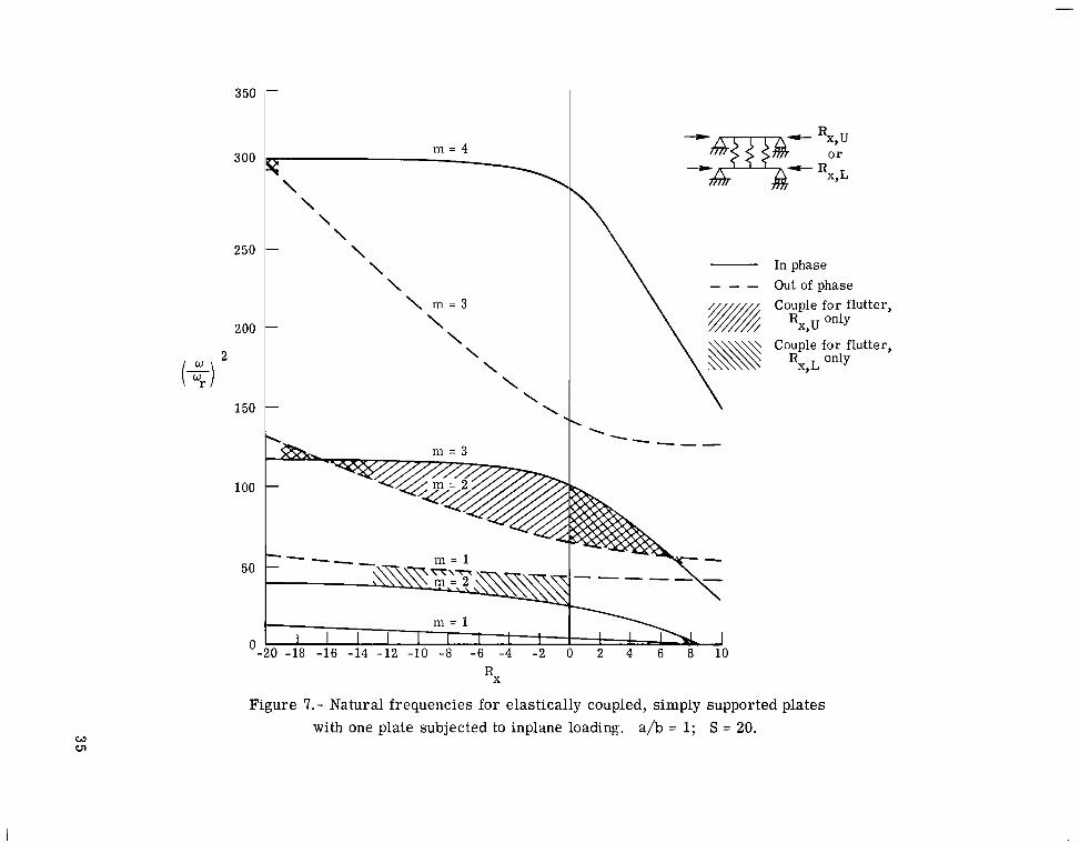
Reference 1 also presents results for two geometrically identical plates with only one plate subjected to inplane loading. These results are compared with closed-form results i n figure 6. Again a/b = 1, S = 20, and both plates are simply supported. Figu r e 6(a) shows flutter boundaries for the upper plate only subjected to inplane loading and figure 6(b) shows similar boundaries for the lower plate subjected to inplane loading. Solid curves denote closed-form results and dashed curves denote two-mode results. In this instance the two-mode solutions are for the most part unconservative and in the region of negative Rx do not exhibit correct trends of the closed-form solution. Examination of figure 7, which shows the natural frequencies of the coupled two-plate system with only one plate subjected to inplane loading, reveals the reason for this behavior.
16

Shaded regions denote that those modes contiguous to the shaded regions coalesce for flutter. Since the two-mode solution is restricted to the first two modes, it can give reliable results only when these modes coalesce for flutter. Thus, the disparity between the exact and two-mode solutions results from the fact that the boundary for the upper plate subjected to inplane loading (fig. 6(a)), except for Rx < -19 and Rx > 6.5 (fig. 7), is governed by a coalescence involving the third natural frequency. When the lower plate is subjected to inplane loading (fig. 6(b)), the flutter boundary from R, = -13 to 0 is governed by a coalescence involving modes 1 and 2, and although the two-mode solution is unconservative, the trend is correct. Outside the region Rx = -13 to 0, mode 3 is again involved and the disparity between the two-mode and closed-form solutions worsens.
Application to Proposed Thermal Protection Systems
Flexible mat system.- In reference 11a thermal protection system (TPS) is proposed which consists of a flexible mat fabricated from fibrous ceramic felt layers covered by a dense ceramic coating bonded to a load carrying primary structure. Since no flutter results for this TPS were presented in reference 11, the present study was undertaken. The TPS was modeled as a system of springs connecting the surface covering to the substructure, and calculations w e r e made to determine the flutter characteristics for such TPS. The system, shown in figure 8, is similar to that considered in figure 6(b) with the exception that the plate exposed to the flow has a much lower flexural stiffness than the unexposed plate and the ends of the exposed plate a r e not necessarily simply supported.
Flutter boundaries which were calculated for this system on the assumption that i t behaves as two spring-connected beams are also shown in figure 8. The solid curves represent flutter boundaries for beams of finite stiffness. The upper boundary results from the assumption that the leading and trailing edges of both beams are simply supported. The lower boundary corresponds to the assumption that the leading and trailing edges of the upper beam a r e supported by deflectional springs with a spring stiffness equal to that of the coupling medium. The two horizontal dashed curves correspond to similar boundary conditions but with the lower beam of infinite bending stiffness.
Figure 9 shows the natural frequencies of the two-beam system as a function of the inplane loading in the lower beam. The solid curves a r e for simple supports and in-phase motion, the dashed curve is the f i rs t out-of-phase mode for simple supports, and the dot-dashed curves a r e for spring supported edges and in-phase motion. Shaded regions between any two curves indicate that those modes contiguous to the shaded regions coalesce for flutter. Again the difference in the two flutter boundaries is related to the modes which coalesce for flutter. Along the boundary for simple supports, in-phase modes 1 and 2 coalesce for flutter up to Rx/Rx,cr = 0.5; between Rx/Rx,cr = 0.5 and approximately 0.67, in-phase modes 2 and 3 coalesce; and beyond Rx/Rx,cr = 0.67, in-phase mode 2 and out-of-phase mode 1 coalesce for flutter. For the boundary corre
17

- - -
sponding to spring supports, in-phase modes 2 and 3 coalesce along the entire boundary to give the flutter condition. For this structure the upper beam has low flexural stiffness and the lower beam has high flexural stiffness (2 orders of magnitude greater than the upper). For both se t s of boundary conditions it is interesting to note that i f the stiffness of the lower beam is considered to be infinite, conservative predictions of X result which are i n good agreement with the corresponding minimum values of X obtained for a lower beam of finite stiffness. This suggests that for configurations in which the lower beam carr ies the inplane loading and is very stiff in relation to the upper beam, use of the simpler solution may be acceptable.
Reusable surface insulation.- Reference 3 presents a modal solution for the flutter~~
behavior of a proposed space shuttle TPS consisting of relatively thick ceramic tiles mounted on a soft viscoelastic foundation which is bonded to a primary load carrying metallic structure. The concept is usually referred to as a reusable surface insulation (RSI) TPS. A Rayleigh-Ritz flutter solution employing 4 free-free beam streamwise modes and 1free-free beam cross-stream mode per tile, and 12 simply supported plate streamwise modes and up to 3 simply supported plate cross-stream modes for the metall ic primary structure was obtained.
The structural model in reference 3 for the viscoelastic foundation neglects viscous effects of the foundation material but is classified as a shear model (in contrast to the Winkler model) in that a point load gives r i se not only to a deflection at that point but to surrounding points as well with an exponential decay of deflection away from the point of application of the force. In reference 3, the Winkler model and shear model were found to give essentially the same results for a single tile and for streamwise multiple tile a r r ays when the viscoelastic foundation was assumed to be cut between tiles. The cut in the foundation is a part of the space shuttle design; hence, the difference in foundation models does not preclude valid comparisons of results from the present analysis with results from reference 3 . Other differences also exist between the two analyses. For instance, the analysis of reference 3 is applicable to multitile a r r ays and assumes the tiles to be free on all edges. The current analysis, however, is restricted to a single two-plate combination which is simply supported along the side edges. Thus, the two analyses can be compared only on a limited basis. One valid comparison is for a/b = 0. Reference 3 gives a flutter value for X of 65 for a two-plate system where the RSI tile has a flexural stiffness of 52 N-m (458 lb-in.), the foundation has coupling-medium spring parameters of Su = 32 and SL = 1971, the lower plate has a flexural stiffness of 0.75 N-m (6.67 lb-in.), the plates a r e 51 cm (20 in.) long, and sea level aerodynamic damping is included. The present analysis gives a value of X of 56 for similar conditions.
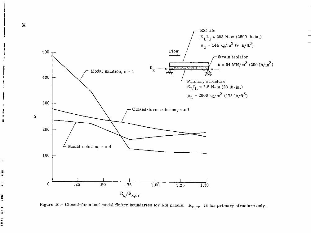
An additional comparison with results from reference 3 is shown in figure 10 in which flutter boundaries a r e given for an a/b = 4 coupled-plate system. Since refer
18

. . -- . . . ., ,. . . . .
ence 3 assumes the tile to be free on all edges, the upper plate was modeled for the current analysis as having stiffness in the streamwise direction only and hence is a beam-type representation of the actual tile. The flutter boundaries shown in figure 10 are presented i n t e rms of h as a function of Rx/Rx,cr where Rx c r is the value of the inplane loading parameter required to buckle the lower plate alone. Structural details of the coupled system are shown in the inset in figure 10. Two boundaries from reference 3 a r e shown; the boundary labeled n = 1 is for a single tile, and the curve labeled n = 4 is for a streamwise a r r ay of four tiles. The boundary labeled closed-form solution is from the present analysis and agrees best with the n = 4 boundary from reference 3. The apparent lack of agreement between the closed-form and modal resul ts for n = 1 may be due to the relatively small number of modes used to describe the motion of the tile. Two rigid-body and two bending modes may not be sufficient to adequately describe the motion of the t i les for n = 1.
Results from the closed-form solution indicate that, although the mass of the upper plate is approximately twice that of the lower plate and the stiffness of the upper plate is two orders of magnitude greater than that of the lower plate, the coupling between the two plates is sufficient to cause the upper plate to respond predominately in bending rather than as a rigid body. The better agreement between the closed-form n = 1 and modal n = 4 flutter boundaries can be attributed to the closeness of the mode shapes for the respective solutions. Figure 11 shows mode shapes for the f i rs t two modes of the coupled system. Since those are the modes which coalesce for flutter, it can be expected that the two solutions might give s imilar flutter results. Reference 3 points out that the salient feature of this coupled system is that although the upper plate has a greater mass and a much higher stiffness than the lower plate, it is the flexibility of the lower plate which governs the response of the system. In fact, the addition of the upper plate and elastic coupling medium actually results in an increase in the dynamic pressure required to flutter the coupled system over that required to flutter the lower plate alone
(9/@coupled = 172 kPa (25 Ps i ) and q/@single -- 26 kPa (4 psi)) . The opposite behavior
occurs for the situation shown in figure 8 in which the upper plate has a much lower flexural stiffness (two orders of magnitude) than the lower plate q Pcoupled = 834 kPa( /(121 psi) and q/psingle = 105 MPa (15 290 psi)). In addition, the presence of the RSI
tiles and viscoelastic foundation increases the buckling load for the coupled system over that for the lower plate alone.
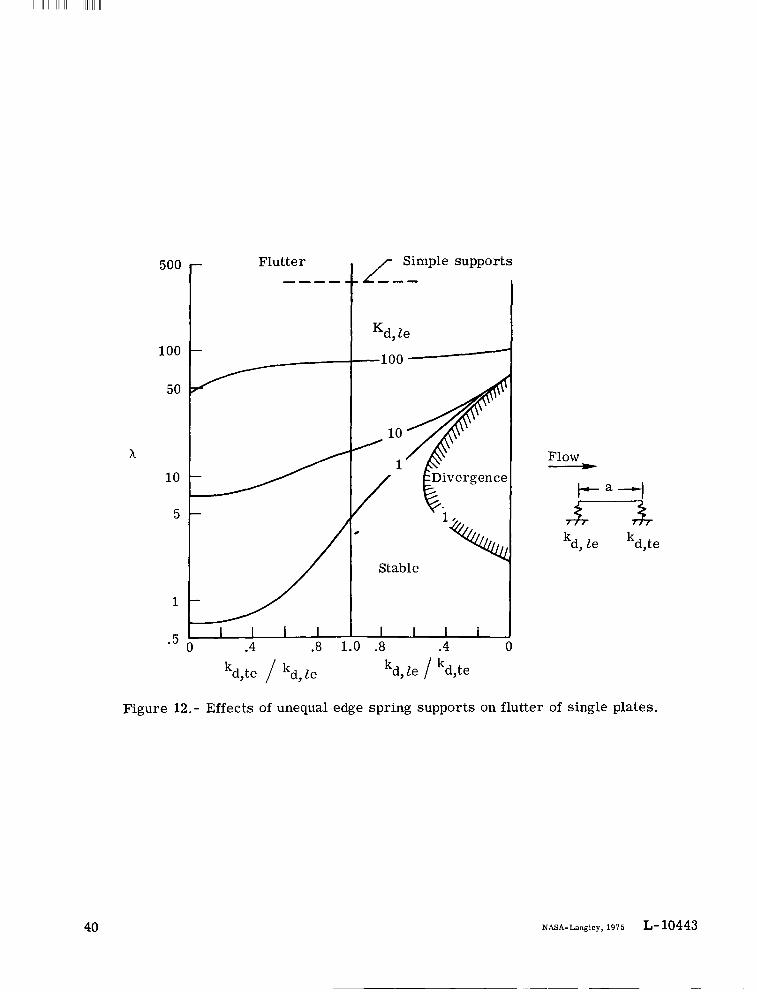
Single plates with unequal supports.- As mentioned i n reference 4, metallic thermal.- .-
protection systems have been proposed which can have rows of continuous supports with widely varying flexibilities normal to the plane of the panel. To i l lustrate the effects on flutter of such unequal deflectional supports, calculations were made using the present analysis for single plates with large streamwise bending stiffness and essentially zero
19

cross-stream bending and twisting stiffnesses. Figure 12 shows stability boundaries in dJze from 0 to 1.0 andte rms of X as a function of spring stiffness ratios kd,te lk
kd,te/kd,Ze from 1.0 to 0. The stability boundaries are for constant values of the spring
stiffness parameter Kd,le of 100, 10, and 1. The dashed curve, shown for comparison, is the value of h for infinite spring stiffness or simple supports.
The curves show large reductions in X from the value associated with simple supports as the edge spring stiffness is decreased. The effect of unequal supports appears to be a function of KdYze. For example, when Kd,le is large (e.g., loo), the effect of reducing the trailing-edge spring stiffness is small as shown for kd,te/kd le < 1. How
ever, when Kd,ze is small (e.g., l ) , a large reduction in the flutter X occurs as the trailing-edge spring stiffness decreases, Additionally, when KdYle is small, large val
ues of the trailing-edge spring stiffness Q le h , t e < 1) may introduce divergence (loss( 9 1 of static stability) which also results i n large reductions in A.
On the basis of the results presented in figure 12, i t appears that in the design of a TPS which employs flexible edge supports to alleviate thermal s t resses , adequate attention must be given to the design of the supports to preclude the drastic reductions of aeroelastic stability margins associated with unequal supports.
CONCLUDING REMARKS
Flutter of two parallel elastically coupled plates was investigated analytically. A closed-form solution including both aerodynamic and hysteretic structural damping was presented for supersonic flutter of flat orthotropic plates coupled by an elastic medium. Both plates were simply supported along the side edges but were supported by deflectional, rotational, and torsional springs of arbitrary stiffness at the leading and trailing edges. Two-dimensional quasi-steady aerodynamics was used i n the analysis.
Because of the large number of variables involved, no attempt was made to conduct extensive parametric studies of the flutter behavior for coupled two-plate systems. However, selected results were presented to illustrate the general flutter nature of such systems. Similar to results for single plates, anomalous zero-dynamic-pressure flutter points were predicted for the two-plate system whenever the frequencies which coalesce for flutter were equal for no airflow. Inclusion of aerodynamic and structural damping i n the calculation removed the computed anomalous zero-dynamic-pressure flutter points for the two-plate system for high length-width ratios (approximately 4) but had little effect for low length-width ratios (approximately 1).
A comparison of flutter results was made for two thermal protection systems proposed for space shuttle. The two systems were similar i n that for each the coupled plates
20
I I I I I I I I I I I I l l I I

differed in flexural stiffness by two orders of magnitude. The two systems differed in that for one the plate of higher flexural stiffness was exposed to the airflow and in the other the plate of lower flexural stiffness was exposed to the airflow. The comparison of flutter results revealed that for coupled two-plate systems with different flexural stiffnesses in the two plates, maximum flutter margins occur when the plate with the higher flexural stiffness is exposed to the flow.
Finally, on the basis of flutter results presented for a single plate with unequal deflectional supports, i t appears that for thermal protection systems which employ flexible edge supports to alleviate thermal s t resses , adequate attention must be given to the design of the supports to preclude the drastic reductions in aeroelastic stability margins associated with unequal supports.
Langley Research Center National Aeronautics and Space Administration Hampton, Va. 23665 November 4, 1975
21
I .


APPENDIX
where
These expressions for the lower plate may be obtained by replacing subscript U with L. Finally,
- kd,te,Ua3 -
Kd,te,U - D1,L
Equations (19) and (21) f rom the main text (repeated here for convenience) are
xu =4 1 (Gx,Lxp+ ALX;: + BLXL) 7T SL
XL = Alep1 x/a + A2eP x a ’ + . . . + A a ep g x/a
With these equations the boundary conditions given by equations (Al) and (A2) may be written as follows:
Upper plate
ffx,uli- K = 0 at x ={} (A34 j = l
23

APPENDIX -
Lower plate
where
1a.=-n4SL (..,L
P ? + XL
P.J 2 +EL1J
For j = 1, 2, 3, . . ., 8. The eight equations given by equations (A3) and (A4) can be combined and written in matrix form as follows:
24
7

kPPENDM
where [ 521 is a 8 X 8 square matrix and {A> is a 8 x 1 column matrix. The elements
L
-+ Gd,te,UKd,te,U(l - "j) + Gt, te ,L%,te ,L(Fr -
for j = l , 2 , 3 , . . . , 8.
25

I I 1 I1 I Ill1
REFERENCES
1. McElman, John A.: Flutter of Two Parallel Flat Plates Connected by an Elastic Medium. AIAA J., vol. 2, no. 2, Feb. 1964, pp. 377-379.
2 . Johns, D. J.; and Taylor P. W.: Vibration and Flutter of Parallel Flat Plates Connected by an Elastic Medium. AIAA/ASME 11th Structures, Structural Dynamics, and Materials Conference, Apr. 1970, pp. 25-35.
3. Dowell, Ear l H.: Vibration and Flutter Analysis of Reusable Surface Insulation Panels. J. Spacecraft & Rockets, vol. 12, no. 1, Jan. 1975, pp. 44-50.
4. Bohon, Herman L.; and Shore, Charles P.: Application of Recent Panel Flutter Research to the Space Shuttle. Part 11 - Influence of Edge Clips and Flow Angularity. NASA Space Shuttle Technology Conference, Volume 111 - Dynamics and Aeroelasticity, NASA TM X-2274, 1971, pp. 247-264.
5. Dixon, Sidney C.: Comparison of Panel Flutter Results From Approximate Aerodynamic Theory With Results From Exact Inviscid Theory and Experiment. NASA TN D-3649, 1966.
6. Shore, Charles P.: Effects of Structural Damping on Flutter of Stressed Panels. NASA TN D-4990, 1969.
7. Libove, Charles; and Batdorf, S. B.: A General Small-Deflection Theory for Flat Sandwich Plates. NACA Rep. 899, 1948. (Supersedes NACA TN 1526.)
8. Hedgepeth, John M.: Flutter of Rectangular Simply Supported Panels at High Supersonic Speeds. J. Aeronaut. Sci., vol. 24, no. 8, Aug. 1957, pp. 563-573, 586.
9. Erickson, Larry L.: Supersonic Flutter of Flat Rectangular Orthotropic Panels Elastically Restrained Against Edge Rotation. NASA TN D-3500, 1966.
10. Hess, Robert W.: Experimental and Analytical Investigation of the Flutter of Flat Built-up Panels Under Streamwise Inplane Load. NASA TR R-330, 1970.
11. Alexander, J. G.: A Non Rigid Reusable Surface Insulation Concept for the Space Shuttle Thermal Protection System. Symposium on Reusable Surface Insulation for Space Shuttle, Volume 111 - Thermal Protection System Design and Optimization, NASA TM X-2721, 1973, pp. 1185-1225.
26
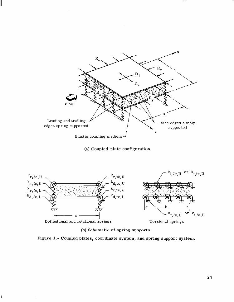
edges spring supported -1 \\Side edges simply
supported Y
Elastic coupling medium
(a) Coupled-plate configuration.
kd, t e, U
kr, te,L
kd, te, L
,-kt, le,U Or kt,te,U
kt,le,L O r kt,te,L
Deflectional and rotational spr ings Torsional spr ings
(b)Schematic of spring supports.
Figure 1.- Coupled plates, coordinate system, and spring support system.
27
I
---- Double plate boundary
Single plate boundary
15 RX WE - Rx x = zqa3 p D1,U
Flutter s=- K a4
4 10
\ RX RX Dl
x1/3
!
5
No flutter
0 3 -5 5 10 15 20
Figure 2.- Flutter boundaries for parallel elastically coupled identical plates and for a single plate; S = 10; no structural and aerodynamic damping.
25

--
I / 0
1 0 -I
50 - Couple f o r flutte
40 30 1
20 I-I
-50 t / / m = 2 "3
m = 4 / , m = 4 .
-60 t / ' I / 1' -70 I I I/ / I I I 1
-10 -5 0 5 - 10 15 20 25 A
Figure 3. - Vibration modes which coalesce for flutter of simply supported identical plates. S = 10.

W 0
i
l6 r = 0.01, ga = 0.00342 X 2 l 3
14
12
10 Flutter
Rx f o r static
No flutter
6
I \ / \ n- / 4 I- 1\ I \I \ I l l \ /
I I \ I ll I I U l I Y I v
2
I I I Y I I I I I I I I I 0 1 2 3 4
Rx
Figure 4.- Flutter boundaries for simply supported identical plates. a/b = 4; S = 10.

--- --
Flow -Flutter 1200
\\ I I1000
\ i I \ \ Closed-form solution, double plate
800 --- Two-mode solution, ref. 1
x \ 0 Two-mode solution, ref. 2
Closed-form solution, single plate 600 -- Aerodynamic damping, ref. 2
400 \\\ No f : t ter
200
0 I 1 -10 -8 -6 -4 -2 0 2 4 6 8 10
(a) S = 20.
Figure 5. - Closed-form and two-mode flutter boundaries for simply supported identical plates. a/b = 1.
w CL
- - -
1200
1000
a oo
600
400
200
0
Flow --L,
Flutter
Closed-form solution, double plate - - - Two-mode solution, ref. 2
Closed-form solution, single plate
Rx
(b) S = 10.
Figure 5. - Concluded.
X

- - -
1600
Flow\ _f
\1400 \
\ Flutter
\ \ -z-Rx
1200 \ \ \
1000
A 800
600
400
200
\ Closed-f or m solution \ Two-mode solution, ref. 1
0 1 1 I I I 1 I
Rx
(a) Upper plate subjected to inplane loading.
Figure 6.- Closed-form and two-mode flutter boundaries with one plate subjected to W inplane loading. S = 20. W
-l 2 O 0 r
I
1000
Flow
Flutter
1
I I \ \
ed-form solution - Two-mode solution, ref. 1
I 2 4 6 8 1 0
(b) Lower plate subjected to inplane loading.
Figure 6. - Concluded.
--- --
350
300
250
200
2
150
100
50
0
r -Rx,Um = 4 $=$-RZfL
\ \ \ \- \
\ In phase
\ - - - Out of phase \ m = 3
- \ \ \ \m \\ Couple for flutter,
\ Rx,L only
\ \- \ \
\
-
-20 -18 -16 -14 -12 -10 -8 -6 -4 -2 0 2 4 6 8 10
Rx
Figure 7. - Natural frequencies for elastically coupled, simply supported plates with one plate subjected to inplane loading. a/b = 1; S = 20.
w cn

--- Schematic of woven mat
Surface fabric Dense ceramic coatings woven from provide moisture ba r r i e r Ceramic surface coating ceramic yarns and high emittance EUIU = 13.6 N-m (120 lb-in.)
Surface felt
Multiple layers of compacted ceramic felts Woven mat
Vertical \ 3 reinforcements
93 to 160 kg/m k = 71 MN/m3 (260 lb/in3) on 0.5-cm centers density range--It--
Vertical Substructure reinforcement ELIL = 2 kN-m (18000 lb-in.)ceramic yarn
1200 Simply supported leadingand trailing edges
Flutter
-800 Spring supported leading
x Simply supported with and trailing edges rigid substructure
Spring supported with rigid substructure
I I I I 0 .2 .4 .6 .8 1.o
Rx/Rx,cr
Figure 8,- Flutter boundaries for proposed TPS.

---
Simply supported, in phase --- Simply supported, out of phase
Spring supported, in phase
VIA Couple for flutter, simply supported
i\\F .Couple for flutter, spring supported
ntical for both boundary conditions)
0 .2 .4 .6 .8 1.0
Rx/ Rx,cr
Figure 9.- Natural frequencies for proposed TPS.
500
400
300
x
200
100
0
RSI tile EUIU = 283 N-m (2500 lb-in.)
pu = 144 kg/m 3 (9 lb/ft 3) Flow
Strain isolator
k = 54 MN/m3 (200 lb/in3)
Modal solution, n = 1
Primary structure ELIL = 2.5 N-m (23 lb-in.)
pL = 2800 kg/m3 (173 lb/ft3)
Closed-form solution, n = 1
L Modal solution, n = 4 1 I I I I I 1
.25 .50 .75 1.00 1.25 1.50
Figure 10.- Closed-form and modal flutter boundaries for RSI panels. %,cr is for primary structure only.
I

0
,-Closed form 1
W
f
Wmax Modal
0 Upper plate
Closed fo rm
Mode - 1
W
Wmax Modal
rl .25 .50 .75 1.oo Lower plate
/Closed fo rm
W
-1 1 -~ I I Upper plate
Closed fo rm
Mode - 2
Lower plate 0 .25 .50 .75 1.00
x/a Figure 11.- Mode shapes from n = 1 closed-form and
n = 4 modal analyses of RSI panels.
39
I I I III I l l I1 I IIIIIIIII
500
100
50
x 10
5
1
. 5
/ Simple supports
Kd, le -100 -
Flow t--a-l75-3
'\ kd, le kd,te
Stable
1111I 0 .4 .8 1 1 .8 .4
kd,te kd,le kd, le / kd,te
Figure 12.- Effects of unequal edge spring supports on flutter of single plates.
40 NASA-Langley, 1975 L-10443

I NATIONAL AERONAUTICS AND SPACE ADMINISTRATION
WASHINGTON, D.C. 20546 POSTAGE A N D FEES P A I D
N A T I O N A L AERONAUTICS A N DOFF1 C I AL BUSI N ESS SPACE A D M I N I S T R A T I O N
PENALTY FOR PRIVATE USE 5300 SPECIAL FOURTH-CLASS RATE 451 U S M A I L
BOOK
1 1 8 001 C 1 IJ - D *7512C4S(d0903DS D E P T OF THE AIR FORCE BF WEAPCNS LABCRATOFY ATTN: T E C H N I C A L L I B B A F Y (SUL) KIRTLANC BFE W M 87117
. .
If Undeliverable (Section 158POSTMASTER : Postal Rlanu:~l)Do Not Return __ .-.
“The aeronautical and space activities o.f the UhZed States shall be conducted so as t o contribute . . . t o the expansion of human knowledge of phenomena +.. the atmosphere and space. T h e Administration shall provide fb? the widest practicable and appropriate dissemination of information concerning its activities and the results thereof.”
-NATIONAL AERONAUTICSAND SPACE ACT OF 1958
NASA SCIENTIFIC AND TECHNICAL PUBLICATIONS TECHNICAL REPORTS: Scientific and ,
technical information considered important, complete, and a lasting contribution to existing knowledge.
TECHNICAL NOTES: Information less broad in sco,pe but nevertheless of importance as a contribution to existing knowledge.
TECHNICAL MEMORANDUMS: Information receiving limited distribution because of preliminary data, security classification, or other reasons. Also includes conference proceedings with either limited or unlimited distribution. -CONTRACTOR REPORTS: Scientific and technical information generated under a NASA contract or grant and considered an important contribution to existing knowledge.
TECHNICAL TRANSLATIONS: Information published in a foreign language considered to merit NASA distribution in English.
SPECIAL PUBLICATIONS: Information derived from or of value to NASA activities. Publications include final reports of major projects, monographs, data compilations, handbooks, sourcebooks, and special bibliographies.
TECHNOLOGY UTILIZATION PUBLICATIONS: information on technology used by NASA that may be of particular interest in commercial and other-non-aerospace applications. Publications include Tech Briefs, Technology Utilization Reports and Technology Surveys.
Details on the availability of these publications may be obtained from:
SCIENTIFIC AND TECHNICAL INFORMATION OFFICE
N A T I O N A L A E R O N A U T I C S A N D SPACE A D M I N I S T R A T I O N Washington, D.C. 20546