TECHNICAL NOTE - NASA NOTE D-991 ... ratio of 5.9, a maximum diameter of 3.2 inches, and a ratio of...
36
Z l-- t_ Z NASA TN D-991 TECHNICAL NOTE D-991 PRELIMINARY INVESTIGATION OF AN UNDERWATER RAMJET POWERED BY COMPRESSED AIR By ElmoJ. Mottard and Charles J. Shoemaker Langley Research Center Langley Air Force Base, Va. NATIONAL AERONAUTICS AND SPACE ADMINISTRATION WASHINGTON December 1961 https://ntrs.nasa.gov/search.jsp?R=19980227735 2018-06-10T15:11:02+00:00Z
Transcript of TECHNICAL NOTE - NASA NOTE D-991 ... ratio of 5.9, a maximum diameter of 3.2 inches, and a ratio of...
Zl--
t_
Z
NASA TN D-991
TECHNICAL NOTE
D-991
PRELIMINARY INVESTIGATION OF AN UNDERWATER RAMJET
POWERED BY COMPRESSED AIR
By ElmoJ. Mottard and Charles J. Shoemaker
Langley Research Center
Langley Air Force Base, Va.
NATIONAL AERONAUTICS AND SPACE ADMINISTRATION
WASHINGTON December 1961
https://ntrs.nasa.gov/search.jsp?R=19980227735 2018-06-10T15:11:02+00:00Z

NATIONAL AERONAUTICS AND SPACE ADMINISTRATION
TECHNICAL NOTE D-991
PRELIMINARY INVESTIGATION OF AN UNDERWATER RAMJET
POWERED BY COMPRESSED AIR
By Elmo J. Mottard and Charles J. Shoemaker
SUMMARY
Part I contains the results of a preliminary experimental investi-
gation of a particular design of an underwater ramjet or hydroduct
powered by compressed air. The hydroduct is a propulsion device in
which the energy of an expanding gas imparts additional momentum to a
stream of water through mixing. The hydroduct model had a fineness
ratio of 5.9, a maximum diameter of 3.2 inches, and a ratio of inlet
area to frontal area of 0.32. The model was towed at a depth of i inch
at forward speeds between 20 and 60 feet per second for airflow rates
from 0.i to 0.3 pound per second. Longitudinal force and pressures at
the inlet and in the mixing chamber were determined.
The hydroduct produced a positive thrust-minus-drag force at every
test speed. The force and pressure coefficients were functions primarily
of the ratio of weight airflow to free-stream velocity. The maximum
propulsive efficiency based on the net internal thrust and an isothermal
expansion of the air was approximately 53 percent at a thrust coefficient
of 0.i0. The performance of the test model may have been influenced by
choking of the exit flow.
Part II is a theoretical development of an underwater ramjet using
air as "fuel." The basic assumption of the theoretical analysis is that
a mixture of water and air can be treated as a compressible gas. More
information on the properties of air-water mixtures is required to con-
firm this assumption or to suggest another approach. A method is sug-
gested from which a more complete theoretical development, with the
effects of choking included, may be obtained. An exploratory computa-
tion, in which this suggested method was used, indicated that the effectof choked flow on the thrust coefficient was minor.
INTRODUCTION
The basic concept of the hydroduct or underwater ramjet consists
of the production of thrust by the transfer of the potential energy of

2
a compressedgas to a flowing liquid through a mixing process. Waterentering the hydroduct inlet is diffused to s high static pressure andmixed with the expanding gas; the mixture is then expandedthrough theduct exit with a resultant increase in total momentum.A theoreticalanalysis of the hydroduct is presented in relerence i; reference 2 con-tains someresults of tests of a hydroduct.
The hydroduct is of potential interest for the propulsion of surfacecraft designed for high speeds because of certain apparent advantagesover conventional propulsion systems. Becauseof the limitations ofplaning craft in rough water, any significant increase in the speed ofpractical surface craft must be accomplished with hydrofoils. It hasbeen proposed that the hydroduct and the ducts to supply air to it couldbe contained within the hydrofoils and supporting struts. Also, it hasbeen conjectured that such a system could have less frontal area, ahigher speed capability_ and lower noise level than supercavitatinggear-driven propellers; however, an evaluation is not possible at thepresent time because of insufficient hydroduct data. Becauseno staticthrust is developed by the hydroduct, the system must include an auxiliarypropulsion device.
Becauseof the apparent advantages of the hydrofoil-hydroduct systemfor propulsion of high-speed surface craft, s preliminary investigationof a simple axisymmetric air-powered hydroduct has been madein Langleytank no. i (this facility has recently been transferred to the DavidTaylor Model Basin) to evaluate the thrust-producing capability of sucha device. The hydroduct was towed at shallow draft at speeds between20 and 60 feet per second with variations in airflow rate from 0.i to0.3 pound per second. Measurementswere madeof the towing force andpressures at the inlet and maximum-areasection. The results of thesetests are described in part I of this report.
As a result of the preliminary experimental investigation it wasapparent that a theory was needed to guide future work. Accordingly_an analysis was madeof the ideal performance of the air-powered hydro-duct. This analysis is presented in part II.
Li24
9
SYMBOLS
A
Af
a
area_ sq ft
frontal area of body, 0.0559 sq ft
speed of sound, ft/sec

CA axial-force coefficient,FA
i OwVoo2Af
Cp pressure coefficient,P - Poo
1 PwV22
CT,c
CT,f
FA
FA,o
FT
M
m
P
Pt
thrust coefficient,T
FTthrust coefficient based on frontal area,
I 2Af2
axial force in forward direction, ib
axial force in forward direction with nose and tail fairings
on model, ib
net Jet thrust, FA - FA,o, ib
Mach number, V/a
mass flow per unit time, slugs/sec
static pressure, ib/sq ft
total pressure, ib/sq ft
q i V 2 ib/sq ftdynamic pressure, _ ,
R
T
t
V
gas constant for air, 53.3
internal thrust, ib
water temperature, 505 ° R
velocity, ft/sec
ft-lb
ib-°F

p
4
W
7
7
_exp
weight flow, ib/sec
adiabatic exponent (assumed to be _.4 for air)
average adiabatic exponent
efficiency
experimental efficiency,
Pw
FTV_
Rtw a log P dP_
density, slugs/cu ft
mass density of water, 1.970 slugsjcu ft
Subscripts:
a
c
d
e
f
i
m
W
wa
oo
air
capture station
diffuser exit
exit station
frontal
inlet
mixing chamber
water
mixture of water and air
free stream
L
i
2
a
9
I. EXPERIMENTAL INVESTIGATION OF HYDRODUCT
By Elmo J. Mottard
HYDRO/_JCT MODEL AND TEST APPARATUS
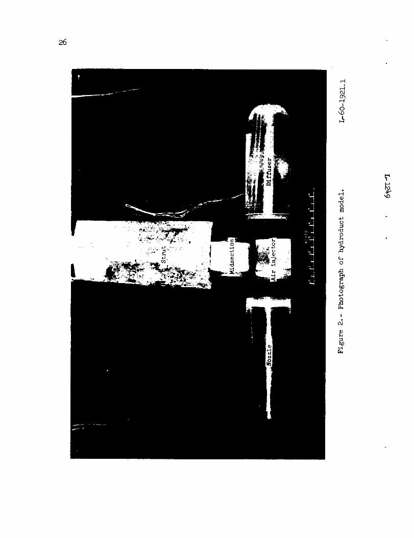
The hydroduct model and towing apparatus are shown in figures i
and 2. The model was supplied by the manufacturer. The diffuser and
nozzle sections were made of clear plastic to facilitate flow observa-
tion. These two pieces were screwed onto a brass midsection which was
welded to a strut. The strut had a duct which connected a compressed-
air supply to the interior of the brass midsection. Metered air was
injected into the stream of water through a cylindrical screen with
openings of 0.001 inch in diameter. The space between the screen and
the outer shell of the midsection constituted an annular settling
chamber.
Pressure-measurement orifices were provided at the maximum-diameter
section of the diffuser and at three points around the inlet_ located
so that an axial asymmetry due to yaw, angle of attack_ or distortion
of the water surface could be detected. Provisions were made for keeping
all lines to pressure taps completely filled with either air or water.
Dynamometer measurements were made of the axial force on the model. Nose
and tail fairings shaped as shown in figure i were used for tare meas-
urements. The towing tank in which the tests were made is described in
reference 3.
PROCEDURE
The speed and airflow rate were held constant during the tests.
In order to minimize strut tares_ the tests were made at a depth of
only i inch to the top of the hydroduct body, with the exception of a
few tests at a 7-inch depth to investigate surface effects. Speeds
of 20, 30, 40, _0, and 60 feet per second and airflow rates of approxi-
mately O.1, 0.2_ and 0.3 pound per second were used. A reference drag of
the strut and hydroduct was obtained with the nose and tail fairings in
place.
RESULTS AND DISCUSSION
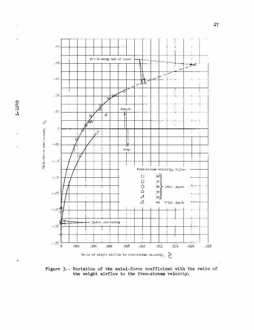
The axial-force coefficient is plotted as a function of the ratio
of weight airflow to free-stream velocity in figure 3. It is evident
6
that the hydroduct is capable of producing thrust since positive values
of the axial-force coefficient were obtained. The increase in draft
from i inch to 7 inches produced a constant decrement in positive axial-
force coefficient of 0.073 which is attribuled to the increased strut
drag. It is believed, therefore, that no surface effect, such as a
reduction in ram pressure or change in flow at the exit due to proximity
of the free surface, occurred.
The thrust coefficient, obtained by subtracting the drag coefficient
of the body with the openings faired over from the axial-force coefficient_
is presented in figure 4. It is apparent from figures 3 and 4 that the
force coefficients are functions primarily cf the ratio of weight air-
flow to free-stream velocity.
The variation of the pressure coefficient at the inlet with the
ratio of weight airflow to free-stream velocity is presented in figure 5.
The variation of pressure around the inlet was small, an indication
that the flow was nearly symmetrical radially despite the proximity of
the free surface. The pressure coefficient at the diffuser exit is pre-
sented in figure 6. In a manner similar to the force coefficients, the
pressure coefficients (figs. 5 and 6) are functions primarily of the ratio
of weight airflow to free-stream velocity. The inlet velocity ratios
were computed from the measured inlet pressures and are presented in
figure 7. That the maximum inlet velocity ratio without airflow (1.53)
approached the ratio of exit area to inlet area (1.65) indicates that
the system total-pressure losses were small for these conditions. For
free-stream velocities greater than 40 feet per second, cavitation
occurred at the inner lip sections of the inlet which precluded deter-
mination of the correct inlet velocity ratio from inlet static-pressure
measurements. The inlet velocity decreases with increasing airflow
until air starts to "puff" out of the inlet; this occurs with a ratio
of weight airflow to free-stream velocity greater than about 0.008.
The inlet velocity can no longer be determined when air leaks out theinlet.
In figure 8 is presented the variation of propulsive efficiency
with thrust coefficient. The propulsive efficiency is defined by
L
i
2
49
Efficiency =Forward speed x Net jet thrust
Power available from expanding air
where the denominator is the power ideally available from an isothermal
expansion of the existing airflow from the pressure measured in the
diffuser to the free-stream pressure. An isothermal expansion was
selected as a criterion approachable by the actual expansion because

L12
4
9
of the great heat capacity of the water (relative to that of air) and
the rapid heat-transfer rate attainable due to the mixing. Use of an
adiabatic expansion as a criterion, for example, could result in effi-
cieneies exceeding i00 percent. The maximum efficiency obtained in
these tests was approximately 53 percent at a thrust coefficient of 0.i0
and speed of 60 feet per second. The range of test variables, however,
was insufficient to determine the maximum attainable efficiency as a
function of thrust coefficient or free-stream velocity. The data indi-
cated that the maximum efficiency probably occurs at a free-stream veloc-
ity greater than 60 feet per second (fig. 8). The hydroduct is compar-
able to a supercavitating propeller for application to a high-speed
hydrofoil configuration; however, the thrust coefficient of 0.i0 was
small compared with that of 1.07 for a supercavitating propeller (com-
puted from ref. 4).
Consideration has been given to the possibility that exit choking
has an effect on thrust production and efficiency. Examination of ref-
erence 5 indicated that air-water mixtures of the range of the investi-
gation could have sonic velocities as low as 70 feet per second. In
the absence of exit static-pressure measurements, exit velocities were
calculated by assuming that the exit pressure was equal to the free-
stream static pressure; most of the resultant values were equal to or
greater than 70 feet per second, indicating the possibility of exit
choking. If the exit flow was indeed choked, the exit pressures might
be greater than the ambient pressure so that some additional expansion
of the flow through the use of a larger exit area may produce greater
thrust.
II. THEORETICAL INVESTIGATION OF AN
AIR-POWEREDUNDERWATER RAM/ET
By Charles J. Shoemaker
ANALYSIS
This theoretical development is for an underwater ramjet that uses
air as a "fuel." The ramjet cycle is as follows: the water captured by
the inlet passes through a diffuser into a mixing chamber; here, com-
pressed air is injected at the mlxing-chamber pressure and water tem-
perature; the resulting water-air mixture is discharged through an exit
nozzle. Because the water-air mixture is less dense than pure water,
the exit velocity exceeds the forward speed and a thrust results.

8
The procedure to be used in the theoretical development of an
underwater ramjet cycle is as follows: A basic equation for thrust
coefficient is presented and this basic equation is then evaluated by
use of simplifying assumptions concerning the fluid properties. Two
assumptions are made concerning the type of flow through the exit nozzle:
(1) that the flow is incompressible and (2) that the flow is compressible.
Basic Thrust-Coefficlent E_uation
A simple underwater ramjet configuration is shown in sketch l, asfollows:
Vco
Pe
Mixing - - - ..... V_
chamber -
I P_
Water
Ae Ai A c
Sketch i
L
l
2
4
9
The internal thrust of a ramjet cycle fo_ steady flow is determined
by the rate of change of momentum of the fluid passing through the ramjet.
If the free-streampressures of the air and w_ter are assumed to be equal,then the internal thrust of the configuration shown in sketch 1 is
where mw and ma are, respectively, the mass flow per unit time of
water and of air entering the ramjet. By rea_ranging terms and using
the equality mw = PwV_Ac, the internal thrus!_ becomes
_ (po-p4Ac+
9
The thrust coefficient based on capture area is defined as
CT,cT
I PwV2Ac
L
i
2
4
9
Upon substituting the thrust relation into the preceding equation and
canceling terms, the following basic equation for internal thrust coef-
ficient is obtained:
(I --_IVI_-_ I) (Pe - P_)AeCT, c = 2 + - + (I)
! wV 2Ac2
Subsonic Discharge
A basic assumption of this analysis is that the ramjet operates
with a subsonic exit. For a subsonic exit, it can be demonstrated that
the exit and free-stream pressures are equal - that is_ Pe = P_. Then
examination of equation (i) shows that the term containing the pressure
and areas becomes zero.
To evaluate the thrust coefficient requires the determination of
the velocity ratio Ve/V _. This ratio is most easily evaluated by
studying, in succession_ the processes of induction, mixing, and dis-
charge. The assumptions for the induction and mixing processes remain
the same regardless of whether the exit nozzle flow is treated as incom-
pressible or compressible.
Inlet and diffuser.- In the induction process it is assumed that
the water acts as an incompressible inviscid fluid. Also, the diffuser
is assumed to deliver the water to the mixing chamber at a negligible
velocity. With the use of these assumptions and Bernoulli's equation,
the total pressure in the mixing chamber can be expressed as
i PwV2Pt,m = p_ +(2)
Mixin_ of air with water.- The assumptions of the mixing processare: the air is injected at the total pressure and total temperature
of the water_ the air and water mix homogeneously without loss in total

i0
pressure, the air does not dissolve in the water nor does the water forma vapor, and the air and water componentsalways have the samevelocity.
Incompressible flow in exit nozzle.- One method of analyzing the
flow through the exit nozzle is to treat the zdxture of air and water
as an incompressible fluid. The nozzle total pressure is assumed to be
a constant and to be equal to the mixing-cham_,er pressure.
Velocity in relation to density: Bernou_li's equation for incom-
pressible flow evaluated at the nozzle exit i_
i 2Pt,m = Pe + _ Pwa,e ve
Substituting the mixing-chamber total pressure (eq. (2)) into this equa-
tion and using the relation P_ = Pe results in
L
I
2
49
i PwV 2 = p_ + i 2P_ + _ _ Pwa,eVe
Solving now for the velocity ratio Ve/V_ gives
Ve _ _ Pw (5)
V_ _ Pwa,e
Density ratio: The following developmenn gives a general expres-
sion for the density ratio. The volume flow of the water-air mixture
at a given station is
Volume flow = mw-_a= (row + ma)
Pwa Pwa
Solving for I/Pwa gives

ii
iP_ra
If both sides of the equation are multiplied by Pw and then simplified,
the following general expression is obtained for the density ratio:
ll ma Pw)= + -- (4)
Note that the air and the mixture densities are associated values and
must be evaluated at a common point.
Velocity ratio: The complete expression for the velocity ratio in
an incompressible mixture of air and water is obtained from equations (3)
and (4) and is
Ve
V_
l+ma PP_,e_mw (5)
Compressible flow in exit nozzle.- Another method of analyzing the
flow through the exit nozzle is to treat the water-air mixture as a com-
pressible fluid. This method is preferred because the actual mixture
is compressible.
For this development, the nozzle total pressure is again assumed
to be a constant and equal to the mixing-chamber pressure and the mixture
of air and water is assumed to act as a compressible gas. By this
approach, the velocity ratio is obtained as a function of an appropriate
adiabatic exponent 7. The estimation of 7 is discussed in detail in
a subsequent section.
Velocity in relation to density: In order to obtain the velocity
ratio Ve/V_, the following compressible-flow relation is used:
12
Pt,wa _ (1 + 7 - 1 )p_ _ _2 7-.l
Subtracting i from each side of this equation _Lnd inserting
7
Ii - 1 Pwa,eVe217-I- 1
with the assumption that Pt,m = Pt,wa, the mixing-chamber total pres-
sure obtained from equation (2) can be rearranged to give
q_ _ Pt,wa _ 1. Using this relation in the preceding equation andP_ P_
solving for V e produces
L
1
2
4
9
i i:?:-:i-Pe Z qoo
Ve = l 7 1 _ + -
Pwa,e
both sides of this equation by V_ and inserting Pw/Pw underDividing
the radical gives
Ve
V_
_ PC/Y: + _
: Pw w
I is usedWhen Pe = P_ is substituted and the identity' q_ = _ pwV_ 2
in the preceding equation, rearranging the resulting equation produces
the following expression for the velocity ratio:

13
V e
V_
7-1
7
(6)
L
i
2
4
9
This velocity ratio (eq. (6)) is the incompressible-flow relation
(eq. (3)) multiplied by a function to compensate for compressibility.
The term under the radical which is enclosed by the braces is referred
to herein as a compressibility function and is designated f(7) because
it contains an unknown 7.
Velocity ratio: The substitution of equation (4) into equation (6)
gives the complete velocity ratio for compressible flow_ which is
i d)7-____1
(maPw) 7 q_+ 7
(7)
Estimation of adiabatic exponent: To obtain the adiabatic
exponent 7 needed in equation (7), the following relation is used:
d (loge P)
d(log e p) =7
(8)
Equation (8) can be obtained from the speed-of-sound equation or from
the relation p = Constant x pT. The latter relation is used in this
development. Differentiation of this relation yields
dp = Constant x 7(_)dp
Substituting p for the quantity Constant x p7 and rearranging gives

14
Using the relations d(log e p) _ dp and d(icg e D) = dp producesP P
d(logep)- 7
d(1oge0)
The evaluation of 7 is begun by differentiating equation (4)
with Pwa and Pa as the variables. When e(_ation (4) is inverted
and differentiated, the result is
d_owa
Pw
_ _) \"_-_a _ 7
Multiply both sides by Ow/Pwa to obtain
Pw (i ma_fma_fPw f dpp__)dOwa Ow--_ + _}\ g/\'_a)\
Replacing pw/Pwa by equation (4) and canceling like terms gives
L
i
2
9
However,
dlOwa
,Owama Pw \
dp = d(log e p) and thereforeP
_'b.b.d(l°ge Pwa) = d(l°ge Pa) + ma pw t
i mw Pa/
15
Invert this relation and multiply by d(log e p) to obtain
d(logep) d(log_p)
(logo0a) ma_jmwPa /
L
i
2
4
9
By use of equation (8) and rearranging terms, the following general
relation for 7 is found:
7 = 7a +mma
(9)
As the mixture travels through the nozzle, 7 is continually
changing. Therefore, the 7 used to evaluate equation (7) was an aver-
age of the mixing-chamber and exit values. The average value of 7 is
-- 7wa,e + 7m7 =
2
Substituting for
terms produces
7wa,e and 7m by using equation (9) and rearranging
7 : 7a
2 ma Pw Pa,e/J
If it is assumed that the air expands isothermally, the relation
= p/RT shows that p is proportional to p. Then, noting thatP
Pm : Pt = P_ + q_ yields
16
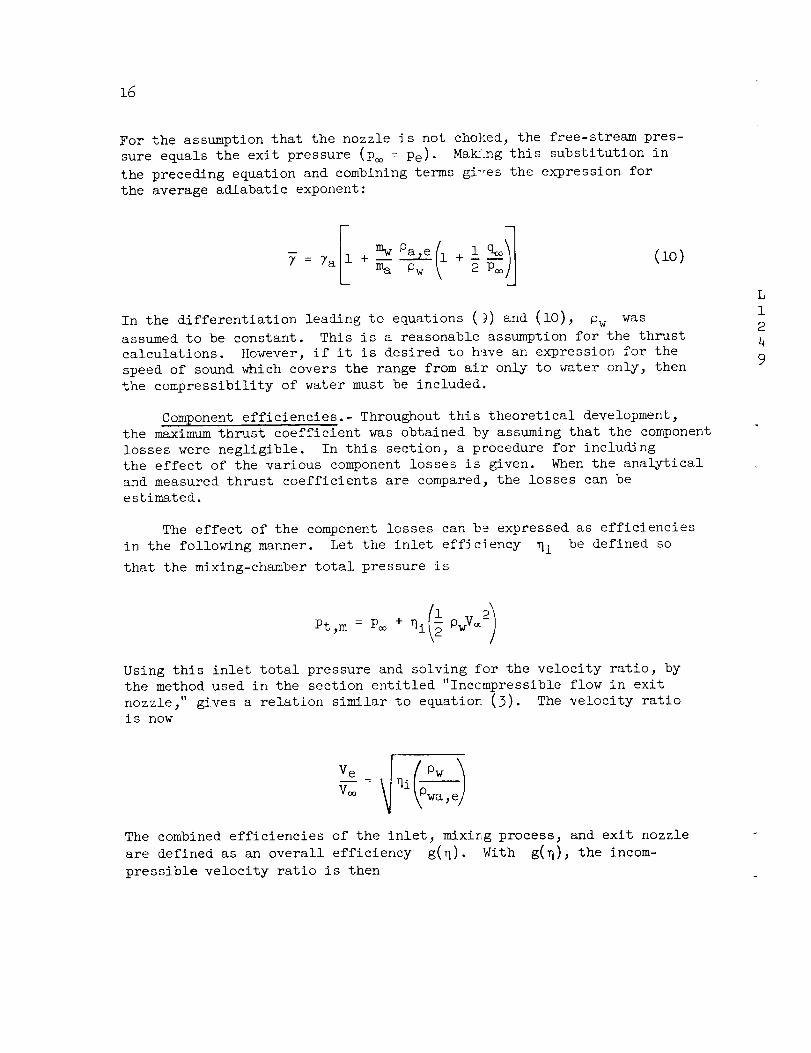
For the assumption that the nozzle is not chohed, the free-stream pres-
sure equals the exit pressure (p_ = Pe)- Ma_!ng this substitution in
the preceding equation and combining terms gi'res the expression for
the average adiabatic exponent:
In the differentiation leading to equations (!7) and (i0), Ow was
assumed to be constant. This is a reasonable assumption for the thrust
calculations. However, if it is desired to have an expression for the
speed of sound which covers the range from air only to water only, then
the compressibility of water must be included.
Component efficiencies.- Throughout this theoretical development,
the maximum thrust coefficient was obtained by assuming that the component
losses were negligible. In this section, a procedure for including
the effect of the various component losses is given. When the analytical
and measured thrust coefficients are compared, the losses can be
estimated.
The effect of the component losses can b9 expressed as efficiencies
in the following manner. Let the inlet efficiency qi be defined so
that the mixing-chamber total pressure is
Pt,m = P_ + _i OwV_-
Using this inlet total pressure and solving for the velocity ratio, by
the method used in the section entitled "Incompressible flow in exit
nozzle," gives a relation similar to equation (3). The velocity ratio
is now
The combined efficiencies of the inlet, mixing process, and exit nozzle
are defined as an overall efficiency g(N). With g(N), the incom-
pressible velocity ratio is then

ZL
17
i q) Pw
By analogy, equation (6) which is for compressible nozzle flow becomes
L
i
2
4
9
(ll)
Working Form of Thrust-Coefficient Equation
The assumptions made to obtain the working form of the thrust-
coefficient equation which was used to study the experimental data are
again stated.
Throughout the ramjet cycle, the component losses were neglected.
The water was considered to be an incompressible fluid. In the mixing
chamber the water velocity was negligible. The injection of air
resulted im a uniform mixture that did not separate. This mixture was
discharged through a nozzle with a subsonic velocity. The nozzle total
pressure was constant and equal to the mixing-chamber pressure. Static
pressure at the nozzle exit was equal to the free-stream static pressure.
The mixture behaved as a compressible gas. An evaluation of the average
synthetic 7, based on an isothermal expansion, was made for this gas.
The internal thrust
flow obtained from equations (i) and (7) is
CT,c = 2(l +
me Pw + imwp
coefficient for subsonic compressible nozzle
/An average value of 7, given by equation (i0), was used.

18
Sonic Discharge Considerations
As mentioned previously for subsonic di:_charge, the nozzle exit
pressure and free-stream pressure are equal. If the exit velocity is
equal to sonic velocity_ the exit and free-s bream pressures are not
necessarily equal and a different procedure _!s necessary to evaluate
the thrust coefficient. Herein are given two ways of estimating the
sonic velocity of a water-air mixture. Then, a suggested procedure to
determine the thrust for a sonic discharge i:_ presented.
Estimation of sonic velocity.- The spee[ of sound of the mixture
is a function of the component densities which are determined by their
respective temperatures. There are two expansion processes which
bracket the temperature range. One is an isentropic expansion and the
second is an isothermal expansion. The speed of sound obtained from
each of these expansions is presented and co_ared.
Isentropic expansion: If the water-air mixture is assumed to pass
through the nozzle so quickly that there is _ittle time for he:_t trans-
fer, the expansion process is essentially ad abatic. Also, the losses
in a nozzle are assumed to be negligible sin:e they are usually small.
With these assumptions, the expansion proces_ is isentropic.
A relation for the speed of sound is ob-_ained by use of the fol-
lowing equation for the velocity of sound:
L
i
2
4
9
i _p
a2(l))
The right-hand side of equation (15) is eval_ated by the use of themixture density obtained from equation (4) _lich is
= Pw + ma i + _Pwa mw
Here the water is to be treated as a compressible fluid; then Pw' Pwa'
and Oa are associated variables and must b_) evaluated at a common
point. When both sides of the equation are _Hvided by a common pressure
and differentiated with respect to this pres_ure_ the following relation
is obtained by rearranging terms:

dPwa _ +
ap
2Pa _Pw ma
_p mw _p
Oa + mal2< m<_]
Using equation (13) in the preceding equation yields
awa 2
Pa _2 i ma I
<h-_j aw---2+ mw aa
19
Solving for awa produces the following general relation for the speed
of sound in the mixture:
awa = a a
+ Im___wlIU)] _ m_/mwima/\PwiJ i + maim w
,,I-1 lm,<'k/Pa\,2 laa'k-2+
(i_)
For mass-flow ratios of the data which were sufficient to produce
thrust_ the denominator of equation (14) is essentially unity.
If the water had been assumled to be incompressible, the speed-of-
sound equation would be
: + (it)awa aa m w + mz _ _w
Equation (15) can be reduced to the numerator of equation (14).
Isothermal expansion: Another method to obtain the speed-of-sound
equation is given by Prandtl in reference 5. Prandtl assumed the air
temperature to be equal to the practically constant water temperature.
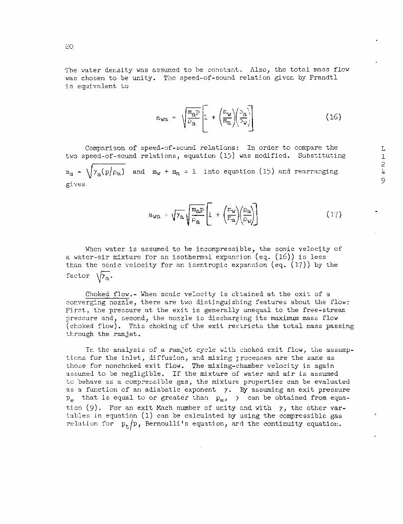
2O
The water density was assumed to be constant. Also_ the total mass flow
was chosen to be unity. The speed-of-sound relation given by Prandtl
is equivalent to
awa = + _aa 5_w (16)
Comparison of speed-of-sound relations: In order to compare the
two speed-of-sound relations, equation (15) was modified. Substituting
aa = _Ta(p/pa ) and m w + ma = i into equation (15) and rearranging
gives
L
i
2
4
9
Y_a m_ I mw Oaawa = + (_)(_)I(17)
When water is assumed to be incompressible, the sonic velocity of
a water-air mixture for an isothermal expansion (eq. (16)) is less
than the sonic velocity for an isentropic expansion (eq. (17)) by the
factor _a"
Choked flow.- When sonic velocity is obtained at the exit of a
converging nozzle, there are two distinguishing features about the flow:
First, the pressure at the exit is generally unequal to the free-stream.
pressure and, second, the nozzle is dischar_iing its maximum mass flow
(choked flow). This choking of the exit restricts the total mass passing
through the ramjet.
In the analysis of a ramjet cycle with choked exit flow, the assump-
tions for the inlet, diffusion, and mixing _rocesses are the same as
those for nonchoked exit flow. The mixing-chamber velocity is again
assumed to be negligible. If the mixture of water and air is assumed
to behave as a compressible gas, the mixture properties can be evaluated
as a function of an adiabatic exponent 7. By assuming an exit pressure
Pe that is equal to or greater than p_, 7 can be obtained from equa-
tion (9). For an exit Mach number of unity and with 7, the other var-
iables in equation (i) can be calculated by using the compressible gas
relation for pt]p, Bernoulli's equation, ard the continuity equation.!
21
L
i
2
4
9
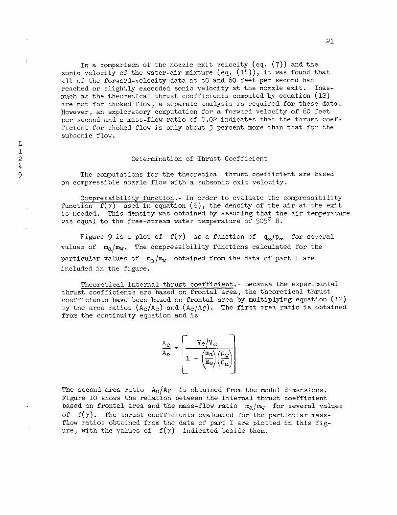
In a comparison of the nozzle exit velocity (eq. (7)) and the
sonic velocity of the water-air mixture (eq. (14)), it was found that
all of the forward-velocity data at 50 and 60 feet per second had
reached or slightly exceeded sonic velocity at the nozzle exit. Inas-
much as the theoretical thrust coefficients computed by equation (12)
are not for choked flow, a separate analysis is required for these data.
However, an exploratory computation for a forward velocity of 60 feet
per second and a mass-flow ratio of 0.02 indicates that the thrust coef-
ficient for choked flow is only about 3 percent more than that for the
subsonic flow.
Determination of Thrust Coefficient
The computations for the theoretical thrust coefficient are based
on compressible nozzle flow with a subsonic exit velocity.
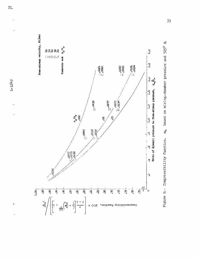
Compressibility function.- In order to evaluate the compressibility
function f(7) used in equation (6), the density of the air at the exit
is needed. This density was obtained by assuming that the air temperature
was equal to the free-stream water temperature of 505 ° R.
Figure 9 is a plot of f(7) as a function of q_/p_ for several
values of ma/m w. The compressibility functions calculated for the
particular values of ma/m w obtained from the data of part I are
included in the figure.
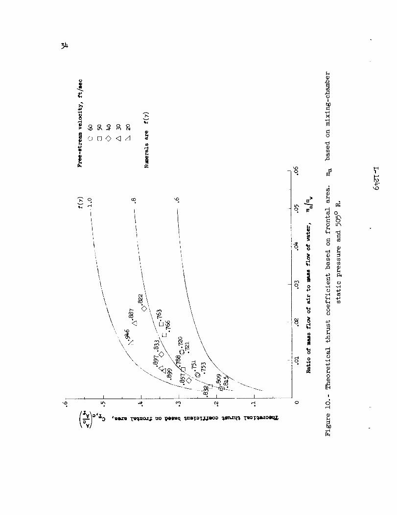
Theoretical internal thrust coefficient.- Because the experimental
thrust coefficients are based on frontal area_ the theoretical thrust
coefficients have been based on frontal area by multiplying equation (12)
by the area ratios (Ac/Ae) and (Ae/Af). The first area ratio is obtained
from the continuity equation and is
Ac
Ae
kmwJ \Pa d
The second area ratio Ae/Af is obtained from the model dimensions.
Figure i0 shows the relation between the internal thrust coefficient
based on frontal area and the mass-flow ratio ma/m w for several values
of f(7). The thrust coefficients evaluated for the particular mass-
flow ratios obtained from the data of part I are plotted in this fig-
ure, with the values of f(7) indicated beside them.

22
Figure 9 can be used in conjunction with figure 10 to provide anestimation of the theoretical thrust coefficient. By choosing a for-ward velocity of the ramjet, the ratio q_/p.o can be calculated. Then,for an assumedmass-flow ratio ma/mw,fig ur_-_9 gives the theoretical
[
compressibility function f(7). With f(7) and the assumed ma/mw,
from figure lO the corresponding theoretical thrust coefficient can beestimated.
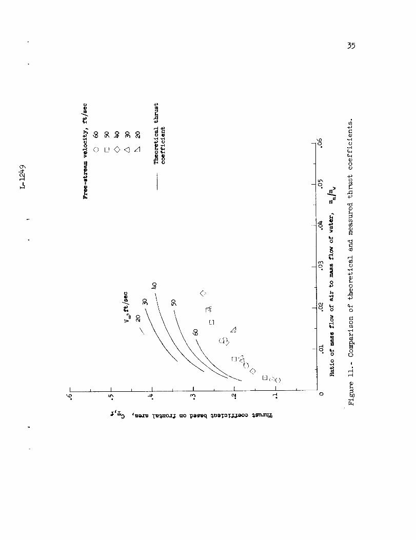
COMPARISON OF THEORY WITH E(PERIMENT
Thrust Coefficient
The theoretical and measured thrust coefficients are presented in
figure ll. The theoretical values have been computed by using the mass
flow obtained from the data of part I and h_le been faired according to
values of constant forward velocity. The differences in the measured
and theoretical thrust coefficients are due to three factors: (1) The
experimental method of obtaining the measured thrust coefficient does
not give the exact internal thrust coefficier_. (2) There are internal
losses associated with the inlet, the mixing process, and the exhaust
nozzle. (3) The theory depends on the validity of the assumptions used
to describe the mixture properties. With the viewpoint that the effect
of factor (i) is negligible and the assumptions of factor (3) are valid,
the internal losses become responsible for the differences in the theo-
retical and measured thrust coefficients.
Efficiency
When the efficiencies of the ramjet components are taken into
consideration, the curves of figure lO represent the product _(7_Eg(_
as indicated by equation (ll). The value of this product is obtained
by transferring the data points of figure ll to figure lO. It is seen
that most of the data lie close to a value o_ _(7_(_ = 0.6. An
estimation of the overall efficiency is obtaLned by dividing the pre-
vious relation by the _(7_ of the data whi:h is given in figure lO.
Then, by using an attainable inlet efficienclT, the mixing and exit
nozzle efficiencies can be estimated.

23
L
1
2
4
9
In the estimation of the inlet efficiency, it is assumed there is
isentropic compression between the capture and inlet stations. For the
remaining compression, regular subsonic diffuser losses are used. From
subsonic diffuser data, these regular subsonic diffuser losses are
known to depend on the diffuser wall angle and to be a certain percent
of the losses for a sudden expansion to the same area ratio. For the
inlet configuration used in the experiment, the efficiency is estimated
to be
_i =
The solid curves of figure 12 give the overall efficiency as a
function of ma/m w. The dashed curves in figure 12 are the results of
dividing the overall efficiency by the estimated inlet efficiency; this
gives an estimation of the mixing and nozzle efficiency. Inasmuch as
the nozzle efficiency is usually very close to unity, these dashed
curves could be assumed to be the mixing efficiency.
CONCLUDING REMARKS
It has been found from a preliminary experimental investigation of
an underwater ramjet that a positive thrust-minus-drag force was pro-
duced at every test speed. The force and pressure coefficients were
functions primarily of the ratio of weight airflow to free-stream veloc-
ity for the conditions of the investigation. The maximum propulsive
efficiency based on the net internal thrust and an isothermal expansion
of the air was approximately 23 percent at a thrust coefficient of O.lO.
The performance of the test model may have been influenced by choking
of the exit flow. A more complete study is required to determine the
applicability of the hydroduct.
The basic assumption of the theoretical analysis is that a mixture
of air and water can be treated as a compressible gas. However, more
information on the properties of air-water mixtures is required to
confirm this assumption or to suggest another approach. A method is
suggested from which a more complete theoretical development, with the
24
effects of choking included, may be obtained. An exploratory computa-
tion, in which this suggested method was useci, indicated that theeffect of choked flow on the thrust coefficient was minor.
Langley Research Center,
National Aeronautics and Space Administration,
Langley Air Force Base, Va., Septer_er 28, 1961.
REFERENCES
i. Staffs of GALCIT and Jet Propulsion Lab.: Jet Propulsion. Air
Tech. Service Command, 1946, pp. 492-52!.
2. Dodge, C. H., and Zwell, Leo: Towing Cha_mel Tests of Two Hydro-bombs and Static Tests of a Hydroduct. Rep. No. 2-3 (Contract
No. W-33-O38-ac-4441), Jet Propulsion L_b., C.I.T., Apr. 22, 1947.
3. Truscott, Starr: The Enlarged N.A.C.A. T_nk, and Some of Its Work.
NACA TM 918, 1939.
4. TachmindJi, A. J., Morgan, W. B., Miller, M. L., and Hecker, R.:
The Design and Performance of Supercavi_ating Propellers.
Rep. C-807, David Taylor Model Basin, Navy Dept., Feb. 1957.
5. Prandtl, Ludwig: Essentials of Fluid Dyn:_mics. Hafner Pub. Co.
(New York), 1952, pp. 330-331.
L
i
2
4
9

2B
\\\
\\
\\
\
i1)
o
.r-t
{1/
ffl
o
I1)
-o
4._
-0
+_e_
o
o
o
ffl
o
@
o
I
26
I
,-I
,4edO_,-4
I0
,4,¢1
,-d0
0
0+._
2.
!
d
°r-I
.g-
27
Oh
o<
r_
.25
.2o
.15
.io
o5
(
oJ
5
-.05 f
/ J
-.LO
-.15 ,' /
0//-.25{ [I
-.50
Air blowing out of inlet ,_-________
_/
J
/
/
Ii
Th] st
!
II
Eag
/
L! / -_
/
/
Free-stream velocity_ ft/sec
[]
i-in. depth
A _j]zJ 2
/3 40 7-2n. depth
Inlet cavltsting
-.350 .002 .004 .006 .008 .010 .012 .014 .016 .018
w a
Ratio of weight airflow to free-stream velocity, V--_
Figure 3.- Variation of the axial-force coefficient with the ratio of
the weight airflow to the free-streamvelocity.

28
J
C
o
D
°.L_
.2O
.]2
• 0,_
• 04
0
-.OL
-.08
-. 12 Y
I
/ iii
!4
/
Air
. I/
J
' kx
,k
blowing ou_ of inlet--
f
Eree-stre_
Q
[]
0
lJ
veloci _y, ft/sec
6o
5o
4o
3o
2o
r- -- Inlet cavitating
0 .002 .004 .006 .008 ,010 .012 .014 .016 .01.5
W a
Ratio of weight airflow to free-stream veLucity, --V_
kO
Figure 4.- Variation of the thrust coefficient based on frontal area
with the ratio of weight airflow to free-streamvelocity.

29
O_
-4
4
t
i
S
o
D_
.8
.6
.4
.2
0
-.2
-.4
-.6
-.8
-1 .o
I
I
/
\
Free-stream
velocity,
ft/sec
© 60
[] 50
<> 40 1-in.
A 3o2o
40 7-in.
\"_--- Inlet cavitating
depth
depth
-- Air
/,/,
blowin@ out or iLnlet
Orifice
location
-1.2
-1.4
-1.60 .002 .004 .006 .008 .010 .012 .014 .016 .018
w a
Ratio of weight airflow to free-stream velocity,
Figure 5.- Variation of the pressure coefficient at the inlet with the
ratio of weight airflow to free-streamvelocity.
Figure 7-- Variation of the inlet velocity ratio with the ratio of
weight airflow to free-streamvelocity.

3o
32
lO0
9O
80
©.- 70
_ 6o
,)
_ 5o
.,4
0
m
_ 30
_ 20
10
0
0
city,
6o
5o
4o
3o
20
ft/sec--
•04 .08 .12 .16 .20 .24 .28 •32
Thrust coefficient based on fronta_ area_ CT, f
Figure 8.- Variation of efficiency with thrust coefficient.
.36
kO
3L
33
O_
0
,-I O,l
I _ ] l r I I 1 l 1 J .... I.... L_ __ .... J ---i-A_-
o
0
IbO
°_
o
03
o._
o
tH
°_
o,-It_U_
orJ
!
&
go,-'t
o
Ip
iii
_ M3
_D0
m
q o4:'
0
1o
o
o
i
_0
o
_o
0 _h
@
_ m
_ 4-__ m
0
ul
@
!
d,-t
%
35
C_
m
(J0
0
I
___oo
m
o
oO_ \_
I i I i I ,
• • • • •
I I I ,,-I
$_&O r_e.z_ _o_3 Izo l_etreq _.ae1:OTJ.Jeoo _.sm.n_
o;
_)"43 "_
-o o
0
El
(1)
UI
0 _
• _ "_g0 %_ 0
• 0
_ 0_-0 m
-r-t
o0
,"4
%
o _,,r--t

56
IV
+J-,-4
0,-I
13
m
i
I
l + t ..... L ....... • ..... L.... + iC cO kO
• • •+-+
oe/0
0e
0JC,
e
r-{o
J J G
_J C
0
rH0
4.+ "r'-Ie N_: .,-I
0
ed _
o -,--t
._ (1)
r'-4
o _
_ g_ ,_ cd
o _
o %
t,++A-t+_,,_e,tev, +o,+t L-12_49
4:-_D