Technical Note: MS8608A/MS8609A Digital Mobile Radio Transmitter Tester · · 2016-03-18Slide 1...
40
Technical Note MS8608A/MS8609A Digital Mobile Radio Transmitter Tester
Transcript of Technical Note: MS8608A/MS8609A Digital Mobile Radio Transmitter Tester · · 2016-03-18Slide 1...

Technical Note
MS8608A/MS8609ADigital Mobile Radio Transmitter Tester

Slide 1
MS8609A-E-E-2
MS8608A/MS8609A Digital Mobile Radio Transmitter Tester
Technical Note
November 2012
Anritsu Corporation
Version 2.0

Slide 2
MS8609A-E-E-2
Contents
1. Wireless communication systems
1.1 Using transmitter tester
1.2 Wireless communications
1.3 Analog modulation
1.4 Digital modulation
2. MS860xA Transmitter Tester
2.1 MS860xA Product outline
2.2 Features
2.3 Parts
2.4 Screens
2.5 Installing measurement software
3. Measurement meaning and
principle
3.1 Base Station Tx test items
3.2 Power meter measurements
3.3 Spectrum analyzer measurements
3.3 Modulation analysis measurements

Slide 3
MS8609A-E-E-2
1.1 Using transmitter tester
1.2 Wireless communications
1.3 Analog modulation
1.4 Digital modulation
1. Wireless communication systems

Slide 4
MS8609A-E-E-2
Wireless communication systems include radio, TV, mobile phones,
wireless LANs, etc. Radio and TV uses analog modulation, while
mobile phones and wireless LANs use digital modulation.
Developing, manufacturing, inspecting, and maintaining these
communications systems requires various measuring instruments,
such as power meters, frequency counters, spectrum analyzers,
modulation analyzers, signal generators, and signaling testers. The
transmitter tester combines the functions of a spectrum analyzer,
modulation analyzer, and power meter to measure the transmission
characteristics of these wireless equipment.
1.1 Using transmitter tester

Slide 5
MS8609A-E-E-2
Method name Name of a country Access Modulation method
AMPS USA
1G TACS UK, Japan FDMA Analog FM modulation
NTT method Japan
NMT Northern Europe
GSM Europe, China GMSK
2G PDC Japan TDMA pi/4 DQPSK
IS-136 USA pi/4 DQPSK
IS-95 USA, Japan, etc. CDMA QPSK
EDGE(GSM) Europe TDMA GMSK/8PSK
3G W-CDMA Japan, Europe, etc. QPSK
CDMA 2000 1x USA, Korea, Japan CDMA QPSK
TD-SCDMA China QPSK
3.5G CDMA2k 1xEVDO USA, Korea, Japan TDMA QPSK/8PSK/16QAM
HSDPA Japan, Europe, etc. CDMA QPSK/16QAM
W-LAN Each country CSMA DS, OFDM
(IEEE802.a,b,g) BPSK/QPSK/16QAM/64QAM
WiMAX Each country OFDM
(IEEE802.16) BPSK/QPSK/16QAM/64QAM
1.2 Wireless communications

Slide 6
MS8609A-E-E-2
1.3 Analog modulation
• What is a carrier?
The signal carrier is a high-frequency sine wave for carrying the
the baseband signal.
• What are the three elements of the sine wave?
A0cos ( 0 t + ) A0: Amplitude, 0 = 2f: Frequency, : Phase
• The modulation of the signal carrier changes the baseband signal.
Amplitude Modulation: The amplitude is changed by the signal.
A0 ( 1 + K cos pt ) cos 0 t K: Modulation ratio
Frequency Modulation: The frequency is changed by the signal.
A0cos ( 0 t + mf sin pt ) mf: Frequency deviation
Phase Modulation: The phase is changed by the signal.
A0cos ( 0 t + mp sin pt ) mp: Phase deviation

Slide 7
MS8609A-E-E-2
Data is sent by using 4 wave shapes that
change phase.
Two bits of information are carried in one wave.
Send data
00011110
00 01 11 10
Divide by
every two bits
00 01 11 10
QPSK (Quadrature Phase Shift Keying)
10 10 11 01
1.4 Digital modulation (QPSK)
00
01
10
11
Q
I

Slide 8
MS8609A-E-E-2
Send data
00011111
Divide by every
four bits
0001 1111
Data is sent by using 16 wave shapes with 4
phases and 4 amplitudes.
16QAM (16-position Quadrature Amplitude Modulation)
1.4 Digital modulation (16QAM)
Four bits of information are carried in one wave.
Q
I
0111
0110
0101
0100
1101 1111
1100 1110
1011 0011 1001
1000 1010
0001
0000 0010
1111 1011
1110
1101
1100
1010
1001
1000
0011 0111
0010 0010
0001 0101
0000 0100

Slide 9
MS8609A-E-E-2
2. MS860xA Transmitter Tester
2.1 MS860xA Product outline
2.2 Features
2.3 Parts
2.4 Screens
2.5 Installing measurement software

Slide 10
MS8609A-E-E-2
The MS8608A/MS8609A Digital Mobile Radio Transmitter
Tester is a measuring instrument with functions for testing
various equipment used in digital mobile communications.
It efficiently evaluates the performance of digital mobile
communication equipment supporting various digital
modulation methods.
It can also be used as a spectrum analyzer without any
measuring software.
2.1 MS860xA Product outline

Slide 11
MS8609A-E-E-2
• Single instrument for evaluating all transmission test
items of wireless communication systems
Measurement software:
W-CDMA, HSDPA, W-CDMA Release 5 uplink, PDC, PHS,
IS-95, cdma2000 1x, 1xEV-DO, GSM, EDGE, TD-SCDMA,
ARIB STD-39, T61, T79, W-LAN, etc.
DSP
Power Meter
(Built-in power sensor)
W-CDMA
software
+
+
Spectrum Analyzer
GSM
software
PDC/PHS
software
Up to three software applications can
be installed simultaneously.
2.2 Features

Slide 12
MS8609A-E-E-2
• Built-in power sensor
High-level accuracy from 8 to 50
• Dedicated measurement software for each wireless
communications method
Easy and fast measurement
• Broad analytical bandwidth (up to 20 MHz)
2.2 Features

Slide 13
MS8609A-E-E-2
Tx Tester
key Spectrum
key
Config key
System key
Function
keys
High Power Input +40 dBm Max. Low Power Input +20 dBm Max. I/Q Input
Memory card
2.3 Parts

Slide 14
MS8609A-E-E-2
2.3 Parts
RF Input: MS8608A Frequency: 9 kHz to 7.8 GHz
Max. input level: High (+40 dBm), Low (+20 dBm)
MS8609A Frequency: 9 kHz to 13.2 GHz,
Max. input level: +20 dBm
I/Q Input: Balance and unbalance inputs
Spectrum key: Switches to spectrum analyzer mode
Tx Tester key: Switches to transmitter tester mode
Config key: Switches to configuration mode
System key: Changes measurement software on Tx tester
Function keys: Panel keys linked to screen soft keys
Memory card: For saving waveform data
(ATA flash card or compact flash card)

Slide 15
MS8609A-E-E-2
2.4 Screens (spectrum analyzer)
Press the [Spectrum] key to display the spectrum analyzer screen.
Press the [More] key to
display more soft keys.
Soft keys for
setting items F1 key
F2 key
F3 key
F4 key
F5 key
F6 key
More key
Slide 16
MS8609A-E-E-2
F1 key
F2 key
F3 key
F4 key
F5 key
F6 key
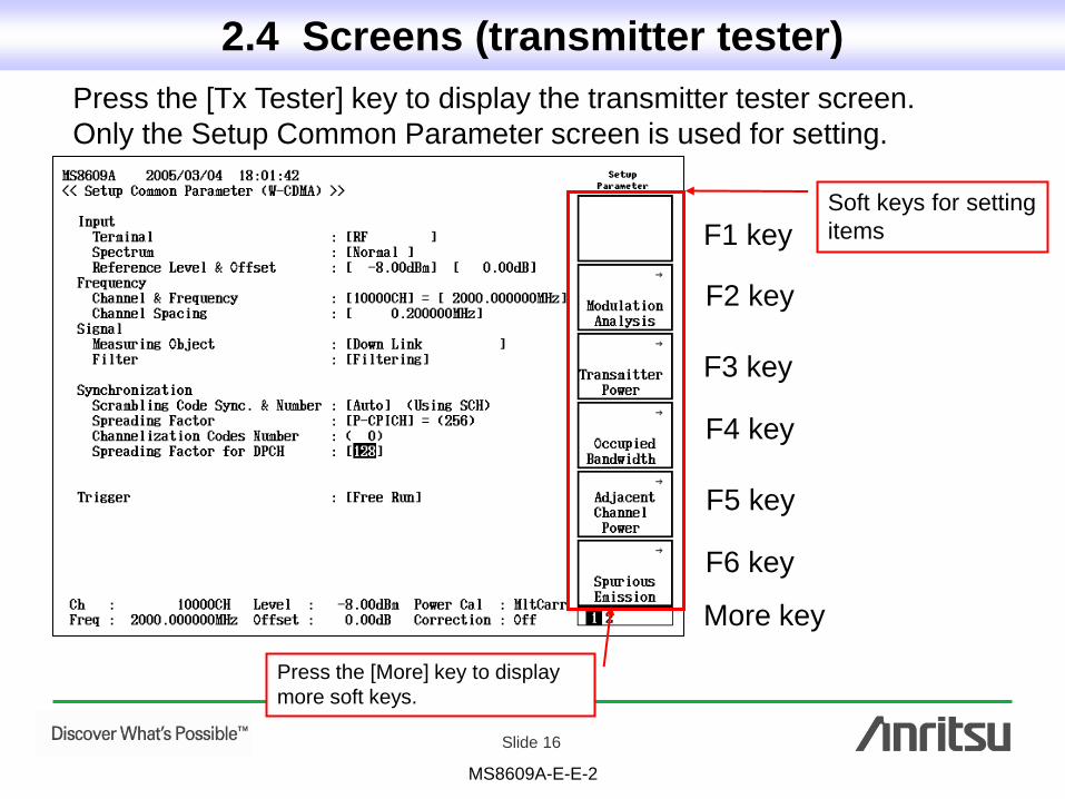
2.4 Screens (transmitter tester)
Press the [Tx Tester] key to display the transmitter tester screen.
Only the Setup Common Parameter screen is used for setting.
Soft keys for setting
items
More key
Press the [More] key to display
more soft keys.

Slide 17
MS8609A-E-E-2
2.4 Screens (change system)
F1 key
F2 key
F3 key
Press the [System] key to display the soft key menu.
When a function
key is pressed, the
system is switched
in a few seconds.

Slide 18
MS8609A-E-E-2
2.5 Installing measurement software
To install other measurement software
(TD-SCDMA GSM)
TD-SCDMA
GSM
Up to three systems can be
installed simultaneously.

Slide 19
MS8609A-E-E-2
2.5 Installing measurement software
1. Insert a PC card with the
measurement software into the
memory card slot.
2. Press the [Config] key.
3. Press the [F4] System Install key.
4. Scroll to Install System using the
rotary knob.
5. Move the the cursor with the [F3]
Choose Memory Card key. When
control of the cursor is returned, press
the [F2 ] Change Installed System key.
6. Use the rotary knob to move the
cursor to the memory card.
7. Press the [F1] System Install key.
The system is installed in about 30 s.
F1
F2
F3
F4
F1
F2
F3
F4
F5
F6

Slide 20
MS8609A-E-E-2
3. Measurement meanings and principles
3.1 Base station transmitter tests
3.2 Power meter measurements
3.3 Spectrum analyzer measurements
3.3 Modulation analysis measurements

Slide 21
MS8609A-E-E-2
3.1 Base station transmitter test items
W-CDMA Tests
Maximum output power
CPICH Power accuracy
Frequency error
Power control steps
Power control dynamic range
Total power dynamic range
Occupied bandwidth
Spurious emission mask
Adjacent channel leakage power ratio
Spurious emissions
Transmit intermodulation
EVM
Peak code domain error
GSM Tests
Output power
Output RF spectrum (modulation)
Output RF spectrum
(switching transient)
Spurious emissions
Radio frequency tolerance
Output level dynamic operation
Modulation accuracy
Intermodulation attenuation

Slide 22
MS8609A-E-E-2
(1) Maximum output power
3.2 Power meter measurements

Slide 23
MS8609A-E-E-2
RF In
Power Meter
DSP RF
Transmitter power With power meter correction function
Power meter Built-in thermal power sensor
(1) Maximum output power
The maximum power of the radio wave (total power) is measured to check
that the value satisfies the standard.
e.g. W-CDMA Standard
Max. power: +43 dBm 2 dB
MS8608A/09A Level accuracy: 0.4 dB

Slide 24
MS8609A-E-E-2
(1) Maximum output power
Transmitter power
Calibration: Corrects difference between result of power meter and result of DSP
Adjust range: Optimizes level in measuring instrument
Transmitter power Power meter
(Single carrier) (Multi-carrier and Burst wave)

Slide 25
MS8609A-E-E-2
(1) Occupied bandwidth (2) Adjacent channel leakage power ratio (3) Spurious
3.3 Spectrum analyzer measurement items
Slide 26
MS8609A-E-E-2
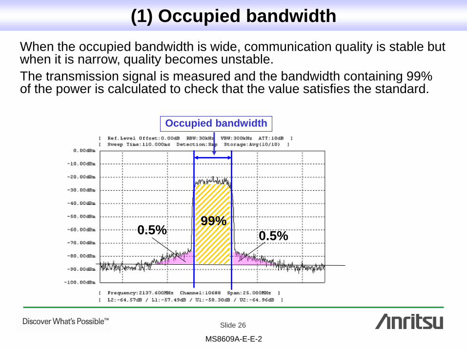
When the occupied bandwidth is wide, communication quality is stable but when it is narrow, quality becomes unstable.
The transmission signal is measured and the bandwidth containing 99% of the power is calculated to check that the value satisfies the standard.
0.5% 0.5% 99%
Occupied bandwidth
(1) Occupied bandwidth

Slide 27
MS8609A-E-E-2
Adjacent channel
Leakage power
Leakage power interferes with the adjacent channel.
Therefore, leakage power into the next channel is measured to check
that the value satisfies the standard.
(2) Adjacent channel leakage power ratio

Slide 28
MS8609A-E-E-2
A lot of wireless communications equipment uses oscillators.
The standard limits power (called spurious) outside the intended radio wave.
Spurious
(3) Spurious
Signal

Slide 29
MS8609A-E-E-2
(1) RF Power
(2) Modulation analysis
(3) Frequency tolerance
(4) EVM and phase error
(5) Constellation
(6) Code domain
3.3 Modulation analysis measurements

Slide 30
MS8609A-E-E-2
(1) RF Power
In a burst wave like GSM and PHS, the rise time, fall time, slot
term, flatness, etc., are measured to confirm that the value
satisfies the standard.
e.g GSM Signal
Rise time Fall time Slot term, Flatness

Slide 31
MS8609A-E-E-2
The received signal that is digital modulation measures the error
margin for the ideal signal. The measurement items are EVM,
magnitude error, phase error, origin offset, etc.
(2) Modulation analysis
<Modulation>
• The signal quality can be evaluated immediately.
• Measurement is fast.
(1.0, 0.0)
(1.1, 0.05)
Ideal signal: R
Error vector: V

Slide 32
MS8609A-E-E-2
Block diagram
The received signal is demodulated, creating the data bits of the received
signal. The data bits are modulated again by the same modulation
method to generate the ideal signal.
Regeneration Demodulation
QPSK
Encoder
OVSF
Spread
Root Nyquist Filter
I/Q Root
Nyquist Filter
OVSF
Dispread
QPSK
Decoder
QPSK
Encoder
OVSF
Spread
Root Nyquist Filter
Root Nyquist Filter
Ideal
signal
Measured signal
Co
mp
ariso
n
Transmitter
(2) Modulation analysis

Slide 33
MS8609A-E-E-2
The phase-locus method is used to calculate the frequency tolerance of
the modulation signal. This method plots the phase difference between
the ideal signal vector and the measured signal vector as data on a time
axis and the time change of the phase difference (angle) is measured.
• When there is frequency tolerance, the line has some angle.
• When there is no frequency tolerance, the line is straight.
(2) Modulation analysis
Ideal signal
Measured signal
Symbol time
Frequency tolerance Phase difference data
This angle is the
frequency tolerance.

Slide 34
MS8609A-E-E-2
• The frequency tolerance of each slot is obtained by using the
phase-locus method. Even if the frequency changes momentarily,
the operating base station can be measured accurately.
• To average the change at the moment continuously, a steady
frequency tolerance is obtained.
(3) Frequency tolerance
e.g. W-CDMA Signal

Slide 35
MS8609A-E-E-2
e.g W-CDMA (Base station)
Frequency error: 0.05 ppm
EVM: <17.5%
For Base Station
Standard 2 10-8/day
Opt-01 5 10-10/day
(4) EVM and phase error
The EVM, phase error and power of each slot can be measured.

Slide 36
MS8609A-E-E-2
Amplitude change
• AGC Oscillation
Phase rotation
• Difference in carrier
frequency
• Difference in
symbol clock
Point extension
• S/N Deterioration
Constellation display is useful for troubleshooting.
(5) Constellation
e.g. W-LAN Signal

Slide 37
MS8609A-E-E-2
(6) Code domain
W-CDMA Code domain
W-CDMA and CDMA2000 use an orthogonal code called spreading code. One of
the spreading codes becomes one channel and a lot of codes are multiple. When
a large amount of information is sent in the spreading factor (SF), the SF is small.
When a small amount of information is sent, the SF is large.
The spread code diverges and
created from left to right as shown
in the figure.
…SF = 256
1
1 1
1-1
1 1 1 1
1 1-1-1
1 1 1 1 1 1 1 1
1 1 1 1 -1-1-1-1
1 1 1 1 1 1 1 1 1 1 1 1 1 1 1 1
1 1 1 1 1 1 1 1 -1-1-1-1-1-1-1-1
1 1 1 1-1-1-1-1 1 1 1 1-1-1-1-1
1 1 1 1-1-1-1-1 -1-1-1-1 1 1 1 1
1 1-1-1 1 1-1-1
1 1-1-1 -1-1 1 1
1-1 1-1
1-1-11
1-1 1-1 1-1 1-1
1-1 1-1 -1 1-1 1
1-1-1 1 1-1-1 1
1-1-1 1-1 1 1-1 1-1-1 1-1 1 1-1
1 1-1-1 1 1-1-1 1 1-1-1 1 1-1-1
1 1-1-1 1 1-1-1 -1-1 1 1-1-1 1 1
1 1-1-1-1-1 1 1 1 1-1-1-1-1 1 1
1 1-1-1-1-1 1 1 -1-1 1 1 1 1-1-1
1-1 1-1 1-1 1-1 1-1 1-1 1-1 1-1
1-1 1-1 1-1 1-1 -1 1-1 1-1 1-1 1
1-1 1-1-1 1-1 1 1-1 1-1-1 1-1 1
1-1 1-1-1 1-1 1 -1 1-1 1 1-1 1-1
1-1-1 1 1-1-1 1 1-1-1 1 1-1-1 1
1-1-1 1 1-1-1 1 -1 1 1-1-1 1 1-1
1-1-1 1 -1 1 1-1 1-1-1 1-1 1 1-1 -1 1 1-1 1-1-1 1
SF = 4 SF = 2 SF = 8 SF =16

Slide 38
MS8609A-E-E-2
(6) Code domain
• The spreading code, spreading factor, and power level of
a multiple signal are measured.
• The received signal de-spreads by each spreading code and the
channel power of each spreading code is calculated.
e.g. Code domain
screen of W-CDMA
Inactive channels
Each channel power

• United StatesAnritsu Company1155 East Collins Blvd., Suite 100, Richardson, TX 75081, U.S.A.Toll Free: 1-800-267-4878Phone: +1-972-644-1777Fax: +1-972-671-1877
• CanadaAnritsu Electronics Ltd.700 Silver Seven Road, Suite 120, Kanata, Ontario K2V 1C3, CanadaPhone: +1-613-591-2003 Fax: +1-613-591-1006
• Brazil Anritsu Eletrônica Ltda.Praça Amadeu Amaral, 27 - 1 Andar01327-010 - Bela Vista - São Paulo - SP - BrazilPhone: +55-11-3283-2511Fax: +55-11-3288-6940
• MexicoAnritsu Company, S.A. de C.V.Av. Ejército Nacional No. 579 Piso 9, Col. Granada11520 México, D.F., MéxicoPhone: +52-55-1101-2370Fax: +52-55-5254-3147
• United KingdomAnritsu EMEA Ltd.200 Capability Green, Luton, Bedfordshire, LU1 3LU, U.K.Phone: +44-1582-433200 Fax: +44-1582-731303
• FranceAnritsu S.A.12 avenue du Québec, Bâtiment Iris 1- Silic 612,91140 VILLEBON SUR YVETTE, FrancePhone: +33-1-60-92-15-50Fax: +33-1-64-46-10-65
• GermanyAnritsu GmbHNemetschek Haus, Konrad-Zuse-Platz 1 81829 München, Germany Phone: +49-89-442308-0 Fax: +49-89-442308-55
• ItalyAnritsu S.r.l.Via Elio Vittorini 129, 00144 Roma, ItalyPhone: +39-6-509-9711 Fax: +39-6-502-2425
• SwedenAnritsu ABBorgarfjordsgatan 13A, 164 40 KISTA, SwedenPhone: +46-8-534-707-00 Fax: +46-8-534-707-30
• FinlandAnritsu ABTeknobulevardi 3-5, FI-01530 VANTAA, FinlandPhone: +358-20-741-8100Fax: +358-20-741-8111
• DenmarkAnritsu A/S (Service Assurance)Anritsu AB (Test & Measurement)Kay Fiskers Plads 9, 2300 Copenhagen S, DenmarkPhone: +45-7211-2200Fax: +45-7211-2210
• RussiaAnritsu EMEA Ltd. Representation Office in RussiaTverskaya str. 16/2, bld. 1, 7th floor.Russia, 125009, MoscowPhone: +7-495-363-1694Fax: +7-495-935-8962
• United Arab EmiratesAnritsu EMEA Ltd.Dubai Liaison OfficeP O Box 500413 - Dubai Internet CityAl Thuraya Building, Tower 1, Suit 701, 7th FloorDubai, United Arab EmiratesPhone: +971-4-3670352Fax: +971-4-3688460
• IndiaAnritsu India Private Limited2nd & 3rd Floor, #837/1, Binnamangla 1st Stage, Indiranagar, 100ft Road, Bangalore - 560038, IndiaPhone: +91-80-4058-1300Fax: +91-80-4058-1301
• SingaporeAnritsu Pte. Ltd.60 Alexandra Terrace, #02-08, The Comtech (Lobby A)Singapore 118502Phone: +65-6282-2400Fax: +65-6282-2533
• P.R. China (Shanghai)Anritsu (China) Co., Ltd.Room 1715, Tower A CITY CENTER of Shanghai, No.100 Zunyi Road, Chang Ning District, Shanghai 200051, P.R. ChinaPhone: +86-21-6237-0898Fax: +86-21-6237-0899
• P.R. China (Hong Kong)Anritsu Company Ltd.Unit 1006-7, 10/F., Greenfield Tower, Concordia Plaza,No. 1 Science Museum Road, Tsim Sha Tsui East, Kowloon, Hong Kong, P.R. ChinaPhone: +852-2301-4980Fax: +852-2301-3545
• JapanAnritsu Corporation8-5, Tamura-cho, Atsugi-shi, Kanagawa, 243-0016 JapanPhone: +81-46-296-1221Fax: +81-46-296-1238
• KoreaAnritsu Corporation, Ltd.502, 5FL H-Square N B/D, 681Sampyeong-dong, Bundang-gu, Seongnam-si, Gyeonggi-do, 463-400 KoreaPhone: +82-31-696-7750Fax: +82-31-696-7751
• AustraliaAnritsu Pty. Ltd.Unit 21/270 Ferntree Gully Road, Notting Hill, Victoria 3168, AustraliaPhone: +61-3-9558-8177Fax: +61-3-9558-8255
• TaiwanAnritsu Company Inc.7F, No. 316, Sec. 1, NeiHu Rd., Taipei 114, TaiwanPhone: +886-2-8751-1816Fax: +886-2-8751-1817
Specifications are subject to change without notice.
1209
Printed on Recycled Paper
Please Contact:
No. MS8609A-E-E-2-(2.00) Printed in Japan 2012-11 MG