Technical Note: Best Practices for Power and Transient Protection ...
16
Technical Note 00840-2700-4811, Rev AB Power and Transient Protection July 2015 Best Practices for Power and Transient Protection on Rosemount ® Radar Transmitters 1 Introduction This document describes best practices for power and transient protection on Rosemount Radar Level Transmitters. Various natural events produce excess transient energy that can enter transmitters via multiple paths. It is critical to practice good grounding techniques in order to optimize the transmitters built-in transient protection. Improper practices can lead to field failures such as erratic mA readings, spiking, difficulty communicating, and possible incorrect levels. This document outlines these best practices and can be used as a guideline during radar installation and start-up. Important Always ground in accordance with Hazardous Location Certifications, national, and local electrical codes.
Transcript of Technical Note: Best Practices for Power and Transient Protection ...
Technical Note00840-2700-4811, Rev AB
Power and Transient ProtectionJuly 2015
Best Practices for Power and Transient Protection on Rosemount® Radar Transmitters
1 Introduction
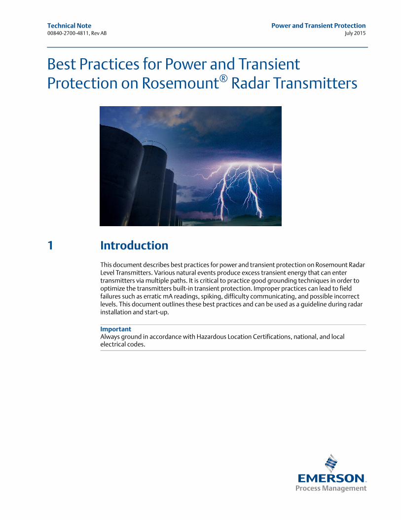
This document describes best practices for power and transient protection on Rosemount Radar Level Transmitters. Various natural events produce excess transient energy that can enter transmitters via multiple paths. It is critical to practice good grounding techniques in order to optimize the transmitters built-in transient protection. Improper practices can lead to field failures such as erratic mA readings, spiking, difficulty communicating, and possible incorrect levels. This document outlines these best practices and can be used as a guideline during radar installation and start-up.
ImportantAlways ground in accordance with Hazardous Location Certifications, national, and local electrical codes.
Technical Note00840-2700-4811, Rev AB
Power and Transient ProtectionJuly 2015
2 Power and Transient Protection
2 Sources of transients
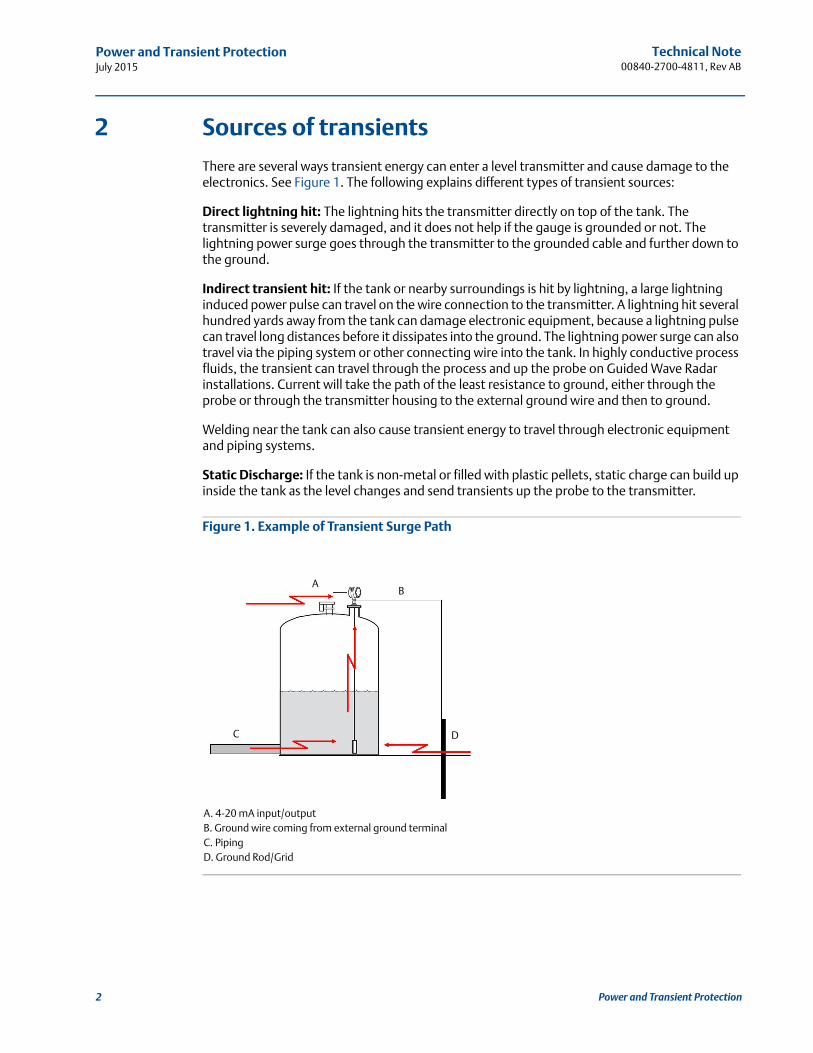
There are several ways transient energy can enter a level transmitter and cause damage to the electronics. See Figure 1. The following explains different types of transient sources:
Direct lightning hit: The lightning hits the transmitter directly on top of the tank. The transmitter is severely damaged, and it does not help if the gauge is grounded or not. The lightning power surge goes through the transmitter to the grounded cable and further down to the ground.
Indirect transient hit: If the tank or nearby surroundings is hit by lightning, a large lightning induced power pulse can travel on the wire connection to the transmitter. A lightning hit several hundred yards away from the tank can damage electronic equipment, because a lightning pulse can travel long distances before it dissipates into the ground. The lightning power surge can also travel via the piping system or other connecting wire into the tank. In highly conductive process fluids, the transient can travel through the process and up the probe on Guided Wave Radar installations. Current will take the path of the least resistance to ground, either through the probe or through the transmitter housing to the external ground wire and then to ground.
Welding near the tank can also cause transient energy to travel through electronic equipment and piping systems.
Static Discharge: If the tank is non-metal or filled with plastic pellets, static charge can build up inside the tank as the level changes and send transients up the probe to the transmitter.
Figure 1. Example of Transient Surge Path
A. 4-20 mA input/outputB. Ground wire coming from external ground terminalC. PipingD. Ground Rod/Grid
AB
C D
Technical Note 00840-2700-4811, Rev AB
Power and Transient ProtectionJuly 2015
3 Proper grounding and transient protection
3.1 Loop power requirements
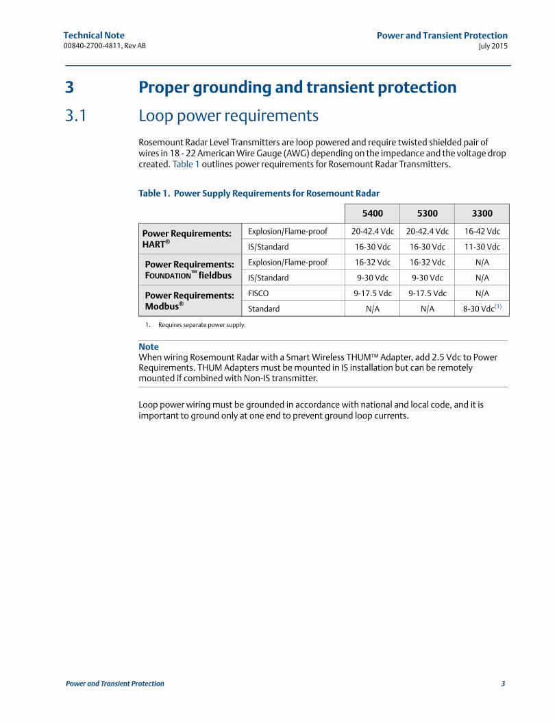
Rosemount Radar Level Transmitters are loop powered and require twisted shielded pair of wires in 18 - 22 American Wire Gauge (AWG) depending on the impedance and the voltage drop created. Table 1 outlines power requirements for Rosemount Radar Transmitters.
Table 1. Power Supply Requirements for Rosemount Radar
NoteWhen wiring Rosemount Radar with a Smart Wireless THUM™ Adapter, add 2.5 Vdc to Power Requirements. THUM Adapters must be mounted in IS installation but can be remotely mounted if combined with Non-IS transmitter.
Loop power wiring must be grounded in accordance with national and local code, and it is important to ground only at one end to prevent ground loop currents.
5400 5300 3300
Power Requirements: HART®
Explosion/Flame-proof 20-42.4 Vdc 20-42.4 Vdc 16-42 Vdc
IS/Standard 16-30 Vdc 16-30 Vdc 11-30 Vdc
Power Requirements: FOUNDATION™ fieldbus
Explosion/Flame-proof 16-32 Vdc 16-32 Vdc N/A
IS/Standard 9-30 Vdc 9-30 Vdc N/A
Power Requirements: Modbus®
FISCO 9-17.5 Vdc 9-17.5 Vdc N/A
Standard N/A N/A 8-30 Vdc(1)
1. Requires separate power supply.
3Power and Transient Protection

Technical Note00840-2700-4811, Rev AB
Power and Transient ProtectionJuly 2015
4 Power and Transient Protection
Figure 2. Possible Field Connections of Rosemount 3300, 5400, or 5300 Transmitters
A. Minimize distanceB. Insulate shieldC. Trim shield and insulateD. Terminals for signalE. Connect shield back to the powerF. Insulate shield and connect to internal ground screw
NoteDo not run the transient protection ground wire with signal wiring as the ground wire may carry excessive current if a lightning strike occurs.
When directly mounting a Smart Wireless THUM Adapter to Rosemount Radar, the loop grounding principles remain the same. The ground wire should be grounded at the power supply and left floating at the THUM Adapter/Radar.
A
DA
BF
CB
E
D
A
A
C
Technical Note 00840-2700-4811, Rev AB
Power and Transient ProtectionJuly 2015
3.2 Housing ground
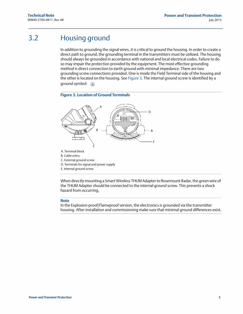
In addition to grounding the signal wires, it is critical to ground the housing. In order to create a direct path to ground, the grounding terminal in the transmitters must be utilized. The housing should always be grounded in accordance with national and local electrical codes. Failure to do so may impair the protection provided by the equipment. The most effective grounding method is direct connection to earth ground with minimal impedance. There are two grounding screw connections provided. One is inside the Field Terminal side of the housing and the other is located on the housing. See Figure 3. The internal ground screw is identified by a ground symbol:
Figure 3. Location of Ground Terminals
A. Terminal blockB. Cable entryC. External ground screwD. Terminals for signal and power supplyE. Internal ground screw
When directly mounting a Smart Wireless THUM Adapter to Rosemount Radar, the green wire of the THUM Adapter should be connected to the internal ground screw. This prevents a shock hazard from occurring.
NoteIn the Explosion-proof/Flameproof version, the electronics is grounded via the transmitter housing. After installation and commissioning make sure that minimal ground differences exist.
A
B
C
D
B
E
5Power and Transient Protection
Technical Note00840-2700-4811, Rev AB
Power and Transient ProtectionJuly 2015
6 Power and Transient Protection
3.3 Transmitter transient protection design
To protect against transient energy, Rosemount Radars utilize the transmitter housing as reference ground. The function of the transmitter transient protection is to lead any excessive surge energy directly to ground. To accomplish this, a separate chassis ground wire is required. This wire should go directly to a ground rod or other ground connection. The transmitter transient protection design is only as good as the grounding. Without proper grounding there is no place for the energy to be redirected.
To achieve optimum transient protection, a transient terminal block is required. The transient terminal block is an optional feature on the Rosemount 5300 and 5400 Series Transmitters, and it is standard in the Rosemount 3300 Series. It is designed to provide a higher degree of protection against transients. In Explosion/Flame-proof transmitters, an internal barrier is added. These diodes limit the energy that is dispatched into the electronics and must be connected to a safety ground.
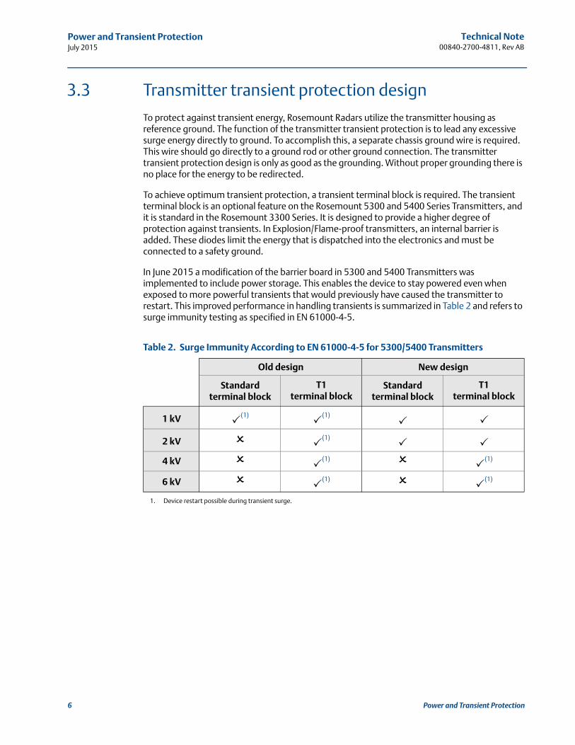
In June 2015 a modification of the barrier board in 5300 and 5400 Transmitters was implemented to include power storage. This enables the device to stay powered even when exposed to more powerful transients that would previously have caused the transmitter to restart. This improved performance in handling transients is summarized in Table 2 and refers to surge immunity testing as specified in EN 61000-4-5.
Table 2. Surge Immunity According to EN 61000-4-5 for 5300/5400 Transmitters
Old design New design
Standard terminal block
T1terminal block
Standard terminal block
T1terminal block
1 kV (1)
1. Device restart possible during transient surge.
(1)
2 kV
(1)
4 kV (1)
(1)
6 kV (1)
(1)
Technical Note 00840-2700-4811, Rev AB
Power and Transient ProtectionJuly 2015
In 5300 and 5400 Transmitters manufactured before June 2015 where device restarts are possible, the following actions can be taken to mitigate the potential for restarts:
Correct grounding
Isolators
Alarm delay
Correct grounding
Correct grounding will substantially reduce the effect caused by transients, but may not fully resolve a recurring problem. Refer to the Wiring section of the Rosemount Series Quick Start Guide (document number 00825-0100-4530) for a detailed explanation on how to properly ground the gauge.
Isolators
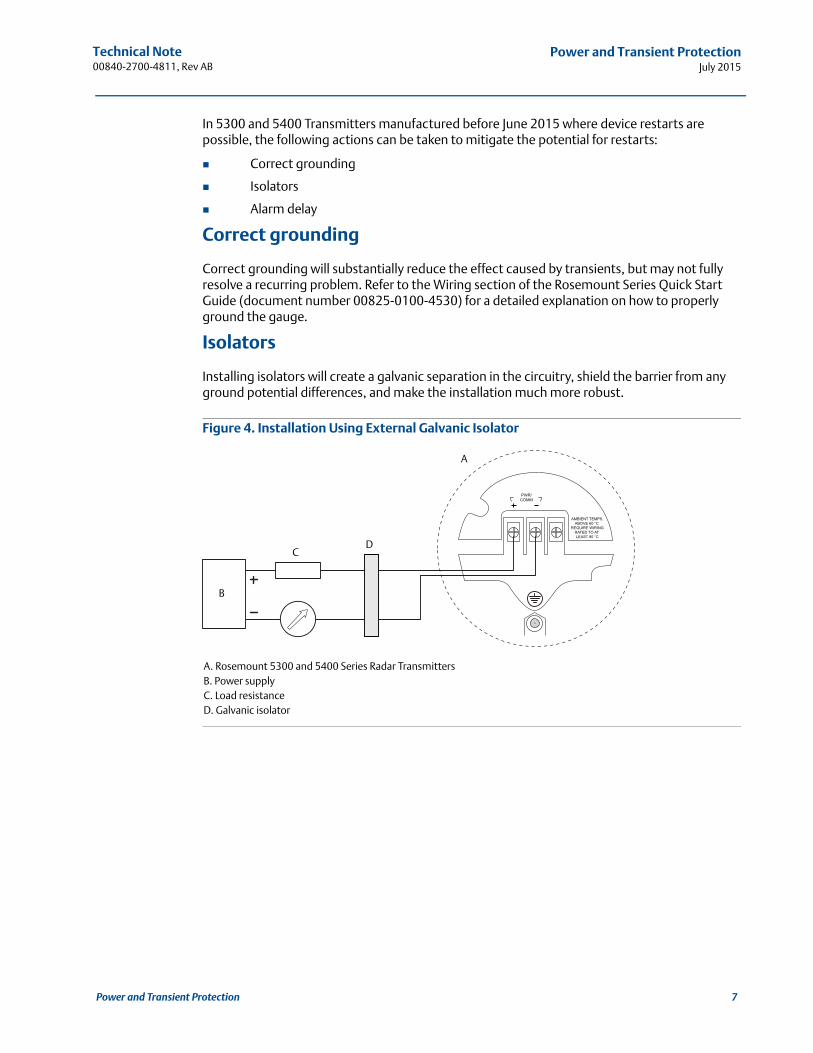
Installing isolators will create a galvanic separation in the circuitry, shield the barrier from any ground potential differences, and make the installation much more robust.
Figure 4. Installation Using External Galvanic Isolator
A. Rosemount 5300 and 5400 Series Radar TransmittersB. Power supplyC. Load resistanceD. Galvanic isolator
B
CD
A
7Power and Transient Protection
Technical Note00840-2700-4811, Rev AB
Power and Transient ProtectionJuly 2015
8 Power and Transient Protection
Alarm delay
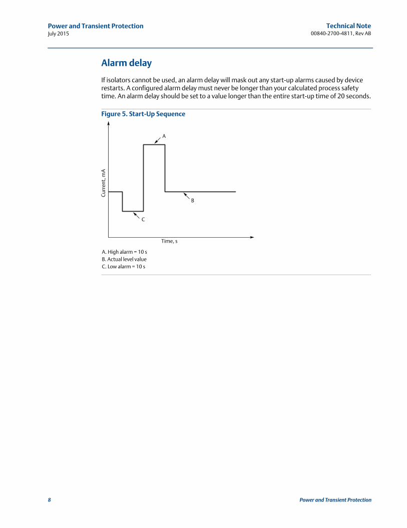
If isolators cannot be used, an alarm delay will mask out any start-up alarms caused by device restarts. A configured alarm delay must never be longer than your calculated process safety time. An alarm delay should be set to a value longer than the entire start-up time of 20 seconds.
Figure 5. Start-Up Sequence
A. High alarm = 10 sB. Actual level valueC. Low alarm = 10 s
Time, s
C
B
A
Cur
rent
, mA
Technical Note 00840-2700-4811, Rev AB
Power and Transient ProtectionJuly 2015
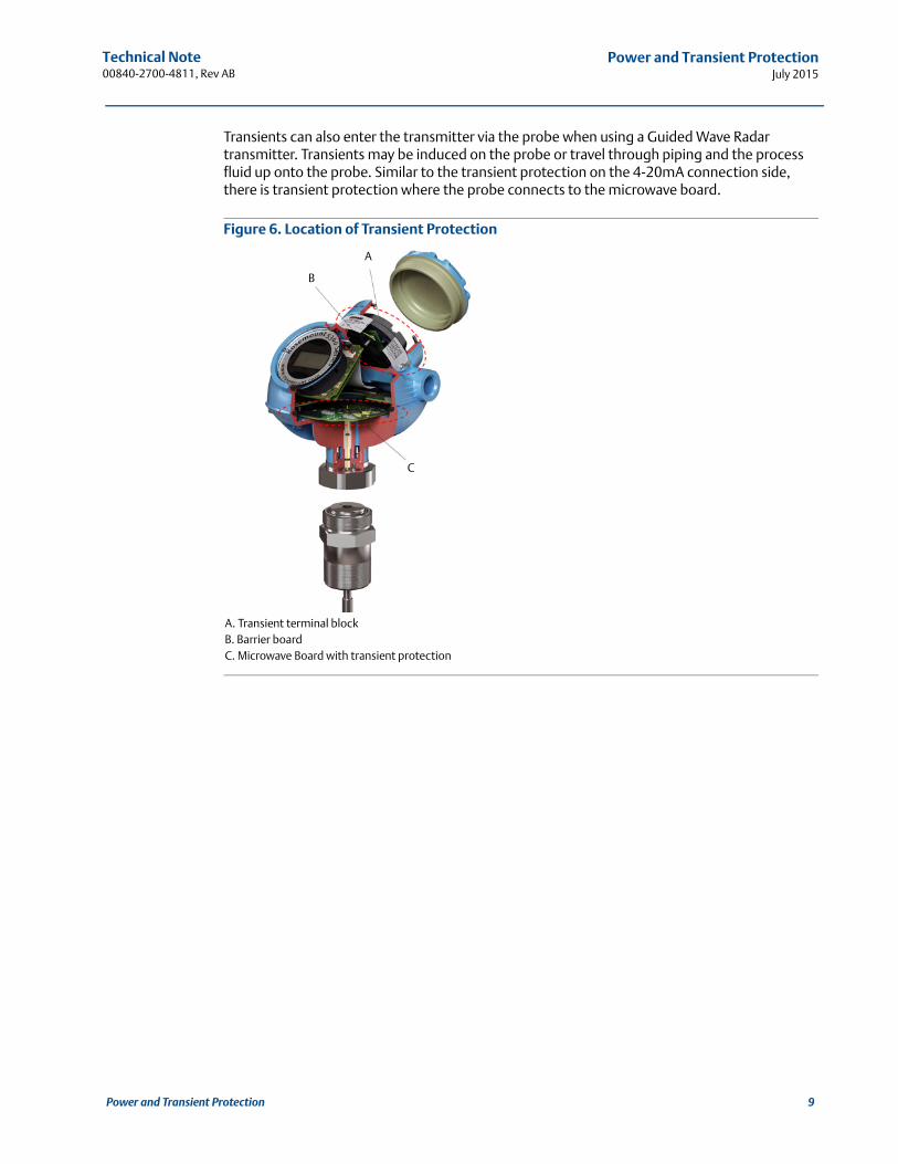
Transients can also enter the transmitter via the probe when using a Guided Wave Radar transmitter. Transients may be induced on the probe or travel through piping and the process fluid up onto the probe. Similar to the transient protection on the 4-20mA connection side, there is transient protection where the probe connects to the microwave board.
Figure 6. Location of Transient Protection
A. Transient terminal blockB. Barrier boardC. Microwave Board with transient protection
A
C
B
9Power and Transient Protection
Technical Note00840-2700-4811, Rev AB
Power and Transient ProtectionJuly 2015
10 Power and Transient Protection
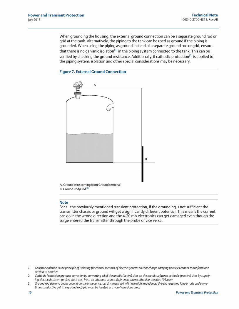
When grounding the housing, the external ground connection can be a separate ground rod or grid at the tank. Alternatively, the piping to the tank can be used as ground if the piping is grounded. When using the piping as ground instead of a separate ground rod or grid, ensure that there is no galvanic isolation(1) in the piping system connected to the tank. This can be verified by checking the ground resistance. Additionally, if cathodic protection(2) is applied to the piping system, isolation and other special considerations may be necessary.
Figure 7. External Ground Connection
A. Ground wire coming from Ground terminalB. Ground Rod/Grid(3)
NoteFor all the previously mentioned transient protection, if the grounding is not sufficient the transmitter chassis or ground will get a significantly different potential. This means the current can go in the wrong direction and the 4-20 mA electronics can get damaged even though the surge entered the transmitter through the probe or vice versa.
1. Galvanic Isolation is the principle of isolating functional sections of electric systems so that charge-carrying particles cannot move from one section to another.
2. Cathodic Protection prevents corrosion by converting all of the anodic (active) sites on the metal surface to cathodic (passive) sites by supply-ing electrical current (or free electrons) from an alternate source. Reference: www.cathodicprotection101.com
3. Ground rod size and depth depend on the impedance. I.e. dry, rocky soil will have high impedance, thereby requiring longer rods and some-times conductive gel. The ground rod/grid must be located in a non-hazardous area.
A
B
Technical Note 00840-2700-4811, Rev AB
Power and Transient ProtectionJuly 2015
3.4 Grounding wire
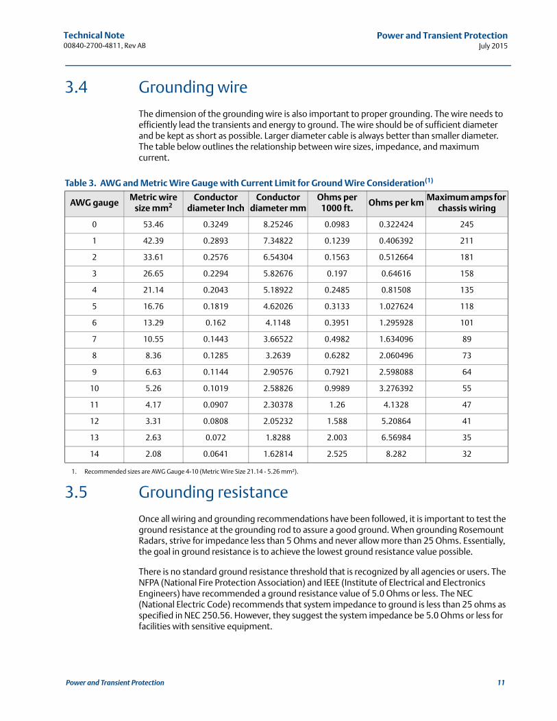
The dimension of the grounding wire is also important to proper grounding. The wire needs to efficiently lead the transients and energy to ground. The wire should be of sufficient diameter and be kept as short as possible. Larger diameter cable is always better than smaller diameter. The table below outlines the relationship between wire sizes, impedance, and maximum current.
3.5 Grounding resistance
Once all wiring and grounding recommendations have been followed, it is important to test the ground resistance at the grounding rod to assure a good ground. When grounding Rosemount Radars, strive for impedance less than 5 Ohms and never allow more than 25 Ohms. Essentially, the goal in ground resistance is to achieve the lowest ground resistance value possible.
There is no standard ground resistance threshold that is recognized by all agencies or users. The NFPA (National Fire Protection Association) and IEEE (Institute of Electrical and Electronics Engineers) have recommended a ground resistance value of 5.0 Ohms or less. The NEC (National Electric Code) recommends that system impedance to ground is less than 25 ohms as specified in NEC 250.56. However, they suggest the system impedance be 5.0 Ohms or less for facilities with sensitive equipment.
Table 3. AWG and Metric Wire Gauge with Current Limit for Ground Wire Consideration(1)
1. Recommended sizes are AWG Gauge 4-10 (Metric Wire Size 21.14 - 5.26 mm²).
AWG gaugeMetric wire
size mm2Conductor
diameter InchConductor
diameter mmOhms per
1000 ft.Ohms per km
Maximum amps for chassis wiring
0 53.46 0.3249 8.25246 0.0983 0.322424 245
1 42.39 0.2893 7.34822 0.1239 0.406392 211
2 33.61 0.2576 6.54304 0.1563 0.512664 181
3 26.65 0.2294 5.82676 0.197 0.64616 158
4 21.14 0.2043 5.18922 0.2485 0.81508 135
5 16.76 0.1819 4.62026 0.3133 1.027624 118
6 13.29 0.162 4.1148 0.3951 1.295928 101
7 10.55 0.1443 3.66522 0.4982 1.634096 89
8 8.36 0.1285 3.2639 0.6282 2.060496 73
9 6.63 0.1144 2.90576 0.7921 2.598088 64
10 5.26 0.1019 2.58826 0.9989 3.276392 55
11 4.17 0.0907 2.30378 1.26 4.1328 47
12 3.31 0.0808 2.05232 1.588 5.20864 41
13 2.63 0.072 1.8288 2.003 6.56984 35
14 2.08 0.0641 1.62814 2.525 8.282 32
11Power and Transient Protection

Technical Note00840-2700-4811, Rev AB
Power and Transient ProtectionJuly 2015
12 Power and Transient Protection
4 Guided wave radar special considerations
When installing Rosemount Guided Wave Radars in non-metal tanks or plastic pellets silos, the Rosemount 5300 is required for additional EMI performance. A ground plane between the electronics, microwave components, and housing results in a more stable microwave performance and minimizes unwanted disturbances. To enhance performance, the following grounding considerations should be practiced in order to ground the tank contents.
4.1 Non-metal tanks
On non-metal tanks, surges can enter the transmitter through the Guided Wave Radar probe, so it is important to ground the fluid content in the tank. If the tank is filled from the bottom, the fluid is usually grounded through the piping. However, in situations where the tank is filled from the top, the fluid may not be properly grounded. In these cases, the grounding can be done by inserting a conductive rod or wire into the tank and connecting it to ground. This rod or wire should be more than 12 inches (30 cm) away from the probe so it does not contact the probe. Also, it should cover the entire height of the tank so the fluid is grounded at all times.
Figure 8. Non-Metal Tank with Connection to Ground
A. Ground wire to ground rodB. Ground Rod/GridC. Min distance between probe and conductive rod/wire = 12-in. (30 cm)D. Ground the fluid via the outlet pipe(1) or conductive rod/wire in tankE. Rod/wire extends to bottom of tank
1. Assuming that piping is grounded through the well and no galvanic isolation is between tank and well.
C
D
A
B
E
D
Technical Note 00840-2700-4811, Rev AB
Power and Transient ProtectionJuly 2015
4.2 Plastic pellets
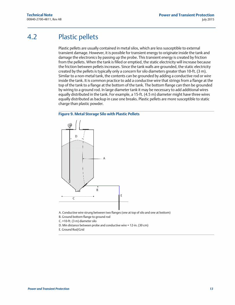
Plastic pellets are usually contained in metal silos, which are less susceptible to external transient damage. However, it is possible for transient energy to originate inside the tank and damage the electronics by passing up the probe. This transient energy is created by friction from the pellets. When the tank is filled or emptied, the static electricity will increase because the friction between pellets increases. Since the tank walls are grounded, the static electricity created by the pellets is typically only a concern for silo diameters greater than 10-ft. (3 m). Similar to a non-metal tank, the contents can be grounded by adding a conductive rod or wire inside the tank. It is common practice to add a conductive wire that strings from a flange at the top of the tank to a flange at the bottom of the tank. The bottom flange can then be grounded by wiring to a ground rod. In large diameter tank it may be necessary to add additional wires equally distributed in the tank. For example, a 15-ft. (4.5 m) diameter might have three wires equally distributed as backup in case one breaks. Plastic pellets are more susceptible to static charge than plastic powder.
Figure 9. Metal Storage Silo with Plastic Pellets
A. Conductive wire strung between two flanges (one at top of silo and one at bottom)B. Ground bottom flange to ground rodC. >10-ft. (3 m) diameter siloD. Min distance between probe and conductive wire = 12-in. (30 cm)E. Ground Rod/Grid
A
C
B
E
D
13Power and Transient Protection
Technical Note00840-2700-4811, Rev AB
Power and Transient ProtectionJuly 2015
14 Power and Transient Protection
5 Wiring best practices
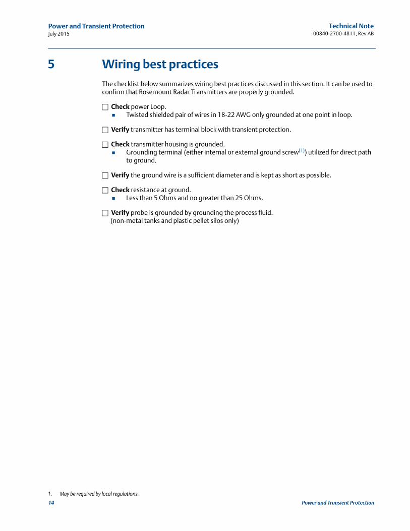
The checklist below summarizes wiring best practices discussed in this section. It can be used to confirm that Rosemount Radar Transmitters are properly grounded.
Check power Loop. Twisted shielded pair of wires in 18-22 AWG only grounded at one point in loop.
Verify transmitter has terminal block with transient protection.
Check transmitter housing is grounded. Grounding terminal (either internal or external ground screw(1)) utilized for direct path
to ground.
Verify the ground wire is a sufficient diameter and is kept as short as possible.
Check resistance at ground. Less than 5 Ohms and no greater than 25 Ohms.
Verify probe is grounded by grounding the process fluid.(non-metal tanks and plastic pellet silos only)
1. May be required by local regulations.
Technical Note 00840-2700-4811, Rev AB
Power and Transient ProtectionJuly 2015
6 Troubleshooting
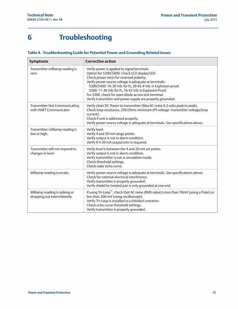
Table 4. Troubleshooting Guide for Potential Power and Grounding Related Issues
Symptoms Corrective action
Transmitter milliamp reading is zero.
Verify power is applied to signal terminals. Option for 5300/5400: Check LCD display/LED.Check power wires for reversed polarity.Verify power source voltage is adequate at terminals: 5300/5400: 16-30 Vdc for IS, 20-42.4 Vdc in Explosion-proof. 3300: 11-30 Vdc for IS, 16-42 Vdc in Explosion Proof.For 3300, check for open diode across test terminal. Verify transmitter and power supply are properly grounded.
Transmitter Not Communicating with HART Communicator.
Verify clean DC Power to transmitter (Max AC noise 0.2 volts peak to peak).Check loop resistance, 250 Ohms minimum (PS voltage -transmitter voltage/loop current).Check if unit is addressed properly. Verify power source voltage is adequate at terminals. See specifications above.
Transmitter milliamp reading is low or high.
Verify level.Verify 4 and 20 mA range points.Verify output is not in alarm condition.Verify if 4-20 mA output trim is required.
Transmitter will not respond to changes in level.
Verify level is between the 4 and 20 mA set points.Verify output is not in alarm condition.Verify transmitter is not in simulation mode.Check threshold settings.Check radar echo curve.
Milliamp reading is erratic. Verify power source voltage is adequate at terminals. See specifications above.Check for external electrical interference.Verify transmitter is properly grounded.Verify shield for twisted pair is only grounded at one end.
Milliamp reading is spiking or dropping out intermittently.
If using Tri-Loop™, check that AC noise (RMS value) is less than 70mV (using a Fluke) or less than 200 mV (using oscilloscope).Verify Tri-Loop is installed in a shielded container.Check echo curve threshold settings.Verify transmitter is properly grounded.
15Power and Transient Protection

Technical Note00840-2700-4811, Rev AB
July 2015
Global HeadquartersEmerson Process Management 6021 Innovation Blvd.Shakopee, MN 55379, USA
+1 800 999 9307 or +1 952 906 8888+1 952 949 7001 [email protected]
North America Regional OfficeEmerson Process Management 8200 Market Blvd.Chanhassen, MN 55317, USA
+1 800 999 9307 or +1 952 906 8888+1 952 949 7001 [email protected]
Latin America Regional OfficeEmerson Process Management 1300 Concord Terrace, Suite 400Sunrise, Florida, 33323, USA
+1 954 846 5030+1 954 846 [email protected]
Europe Regional OfficeEmerson Process Management Europe GmbHNeuhofstrasse 19a P.O. Box 1046CH 6340 BaarSwitzerland
+41 (0) 41 768 6111+41 (0) 41 768 6300 [email protected]
Asia Pacific Regional OfficeEmerson Process Management Asia Pacific Pte Ltd1 Pandan CrescentSingapore 128461
+65 6777 8211+65 6777 0947 [email protected]
Middle East and Africa Regional OfficeEmerson Process Management Emerson FZE P.O. Box 17033,Jebel Ali Free Zone - South 2Dubai, United Arab Emirates
+971 4 8118100+971 4 8865465 [email protected]
Standard Terms and Conditions of Sale can be found at: www.rosemount.com\terms_of_sale.The Emerson logo is a trademark and service mark of Emerson Electric Co.Rosemount and Rosemount logotype are registered trademarks of Rosemount Inc.THUM and Tri-Loop are trademarks of Rosemount Inc.HART is a registered trademark of the FieldComm Group.FOUNDATION fieldbus is a trademark of the FieldComm Group.Modbus is a registered trademark of Modicon, Inc.All other marks are the property of their respective owners.© 2015 Rosemount Inc. All rights reserved.