TECHNICAL NOTE 4085 Cornell University - NASA · TECHNICAL NOTE 4085 ... By P. P. Bijlaard Cornell...
98
I ., TECHNICAL NOTE 4085 METHOD OF SPLIT RIGIDITIES AND ITS APPLICATION TO VARtOUS BUCKLING PROBLEMS By P. P. Bijlaard Cornell University Washington Jtiy 1958 ~ r AFM!X mtx’c,m.i. I.’E:Afiy z EC https://ntrs.nasa.gov/search.jsp?R=19930085123 2018-07-16T13:18:09+00:00Z
Transcript of TECHNICAL NOTE 4085 Cornell University - NASA · TECHNICAL NOTE 4085 ... By P. P. Bijlaard Cornell...

I.,
TECHNICAL NOTE 4085
METHOD OF SPLIT RIGIDITIES AND ITS APPLICATION TO
VARtOUS BUCKLING PROBLEMS
By P. P. Bijlaard
Cornell University
Washington
Jtiy 1958
~
r AFM!Xmtx’c,m.i.I.’E:Afiy
zEC
https://ntrs.nasa.gov/search.jsp?R=19930085123 2018-07-16T13:18:09+00:00Z

TECH LIBRARY KAFB, NM
D NATIONAL ADVISORY COMMITTEE FoR AERONAUTC( 111111111111UDhL+5b
TECHNUU m!m 4085
METHOD OF SPIZT RIGIDITIES AND ITS APPLICATION TO
VARIOUS BU~ PROBLEMS
A comprehendive treatisesented. First the principles
P. P. Bijlasrd
SUMMARY
on the method of split rigidities is pre-upon which the method is based sre discussed.
It is shown on new examples how these principles are applied. Theseapplications sxe divided into problems where all component modes intowhich the actual behavior of a Gomposite structure is split have thessme boundary conditions and into those where these boundary conditionsdiffer. Examples of the first type include sandwich columns tith variousboundary conditions, columns with batten plates, and latticed columns;exsmples of elastic and plastic buckling of sandwich plates with ortho-tropic core and of corrugated-core sandwich plates are also given. Thistype includes problems based on the same principles where only one modehas to be considered. As an example, the buckling stress of homogeneous
4 plates under nonhomogeneous stresses in the@ plane is expressed in termsof their critical stress under homogeneous compression. TO this grOUp
A also belongs the determination of the ultimate load of plates undercompression. An -licit formula is derived for the buckling stress ofstringer psmels which is a new example of the second type of problem.The problems were chosen so that the correctness of the method, whichis basically an approximate one, canbe shownby comparison with exactcalculations or tests.
INTRODUCTION
In several papers a method has been used for calculating the bucklingstresses of structures that buckle in coqosite modes which is called the“method of split rigidities.’* The method consists of splitting thebuckling deflection into two or more component modes and expressing thebuckling stress in terms of the critical loads for these coqonent modes.References 1 to 19 are based partly or completely on this method.
* For example, in a sandwich plate (refs. 5, 9, 11, 12, and 14) thereare three different buckling modes: (1) That of the single faces,
.

2 N4CA TN 4085
●
(2) that of the complete sandwich pbte, assuming the faces to have zeroflexural rigitity but assum3.ngthe core to have infinite shear rigidity,and (3) that of the complete sandwich platej assuming the faces to have
.
zero flexural rigidity and assuming the faces to be infinitely rigidagainst extension. In the case of a T-section (ref. 13) the thee modesare: (1) Bending about the Y-axis situated in the plane of the web,(2) twisting about the sheer center axis, and (3) plate buckling. Inthe case of buckling by general instability of a long cylindrical shell
—
tith stiffening rings under external pressure (ret. 19) the componentmodes are buckling as an orthotropic shell~ assuming the rigidity of therings to be uniformly distributed along the length of the shell, andbuckling of the shell betwee~ the rings. In the case of stringer panels(ref. I-8)practically exact solutions are obtained ~y this method forconventional panel buckling as well as for forced crippling (refs. 16,18, and20).
Formulas for buckling loads or stresses have been derived in earlierpapers and new ones will be presented herein by establishing equationsbetween external and internal actions. In references 1, 2, 3, and 6 theexternal atidinternal actions considered were the external and internalbending moments. In references 7 and 13 bending as well as torsionalmoments were considered. Bending moments in a cross section as well asdeflecting and restraining transverse forces acting on an element wereconsidered in references 4, 9, 11, 13, mcl I-6. The actions and reactionsconsidered in references 14, 15, 17, and 19 were the amounts of work doneby deflecting and restraining forces. Columns and plates with initialdeflections were considered in a footnote of reference 1 and in
““ “i!
reference 15.._-<“s
The method of split rigidities was also applied in the postbucklingrange (refs. 13 ad 17). It is very powerful.and leads to stile resultsin cases where a solution by existing methods is practically impossible.It was successfully used in two other projects (refs. 13 and 17). Untilthe present only a few other investigators have used this method (refs. 21,22, and 23) probably because no general comprehensive treatise on it hasyet been made avaiMble. Therefore the purpose of the present report isto give such a general explanation, with examples of the”rnethodof appli-cation in various special cases.
The present investigation was carried out at Cornell Universityunder the sponsorship and with the financial assistance of the NationalAdvisory Committee for Aeronautics. The e.xmples dealing with theultimate load of plates under compression and with buckling of stringerpanels are part of earlier work done for the Bell Aircraft Corporation.The author tishes to express his a~reciation for the valuable coopera-tion of all concerned md to the BeXL Aircraft Corporation for its per-mission to publish the abovementioned examples.

NACA TN JIa85 3
.
.
A
A,B,D,F
‘d
A~t
%
s.
b
be
c
c
=0
D
D~D~
E
Ec
Es
Et
%c
G=
snm301s
total cross section of column
plastic reduction coefficients
cross section of diagonal
cross section of stiffener
cross section of vertical
for pl&stic buckling of plates
half wave length of buckling for plate
width of plate; also, width of hay of stringer panel
effective width of plate
constant; also spring constant (foundation modulm)
center-to-center spacing of batten plates in built-up column;also, free length of single struts in latticed column
effective free length of single stiuts between batten phtes
deflecting force
ratios of shear
elastic modulus
elastic modulus
elastic modulus
to shear @e
of corrugation
of faces (skin) in sandwich _platejalso,secant nmdulus in section “Ultimate Ioad of Plates UnderCompression”
tangent
tangent
modulus
modulus
modulus of corrugation
of rigidity of sandwich core

4 NACA TN 4085
.
Gx)Gy moduli of rigidity in X- and Y-directions of sandwich core
E total thickness of sandwich column or sandwich plate, t + 2h.
h center-to-center distance of single struts of built-up column;also, thickness.of single face of ss.udwichcolumn or sandwichplate
I moment of inertia
Ic moment of inertia of single strut.of built-up column
If moment of inertia of single face of sandwich plate
L? moment of inertia of reduced built--upcolumn, M12/4
Is moment of inertia of reduced sandwich column or sandwich —
plate, (1/2)h(t+ h)2
K constant
k buckling stress coefficient definedby equation (142)
~,kljk2 buckling stress coefficients referring to cases O, 1, and 2,respectively
ks buckling stress coefficient definedby equation (145)
kb,~,. . . coefficients in equation (104)
II effective length of column
z length of colurm; also, length of stringer panel
Zr/r effective slenderness ratio for reduced case of built-upcolumn
‘eq~ effective slenderness ratio of built-up column
A
M moment
‘+ bending moments
Mw) Mw torsional moments
5
.
.N
xi~
n= Z/c
n’
P
P?q
Q
Q’
R
r
rc
‘x’‘Y
. .‘X9%
s
S,SII,SIV
t
%
v
w
flexural rigidity of homogeneous plate; also, flexural rigidityof face of sandwich plate
flexural rigidity of reduced sandtich plate, given byequation (59)
mxiber of bays
buckling load
of stringer panel
coefficients in equations (108) and (203)
she= force; also, transverse shear force in plate
trsmsverse shear force that would cause a unit angulardistortion in latticed column
restraining force
radius of ~ation of reduced built-up Colummj h/2;r ~ if rx=ry=rx=r
radius of ~ation of single strut of built-up column
ratios defined by equations (78) and (81)
ratios defined by equations (W) and (123)
spring
quarter spring constants for plates
core thickness of sandwich column or sandwich plate; also,thickness of homogeneous plate
normal fiction
translation of single struts per unit shear force inbatten plates
deflection

NACA TN 4085
coordinates
directions
function of y only
angle .-
coefficients defined by equation (A6)
coefficient in equation (102)
factor in equation (35)
aspect ratio of buckle in
angular distortion; also,
elongation
strain
membrane strain
buckled plate, a/b
ratio ‘definedby eqyation (221)
value <<I in equation (228)
reduction factor for plasticity forplates
reduction factor for plasticity for
angle; e = ex = ‘Y H ‘x=eY
ratios definedby equation (73)
ratio defined by equation (226) for
ratio definedby equation (95,)
concentric buckling of
-.
finite deflection of plates
stringer parlel
n-.
Poisson’s ratio
slope of column
normal stress
in case 2 of latticed column
.
.
7NACA TN 4085
‘e normal stress at edge
‘m membrane normal stress
az normal stress in plane parallel to middle plane of sandwichplate
T coefficient in equations (151) and (154)
Q(x,y) function of x and y
9 ratio defined by equation (21.1)
@ defined by equation (212)
n ratio defined by equation (225) for stringer panels
Subscripts:
a
b
cr
e
-w-*.
eq
h
i
m
mid
P
r
s
St.
u
.l.llt
actual (fig. 10(b))
bending
critical
external
equivalent
homogeneous
internal
maximum
center (middle)
postbuckl.~j also, refers to fictitious end deflections asshown in figure 10(b)
reduced case
skin (face) for sdndwich plate; also, secant in section“Ultimate Load of Plates Under Compression”
stiffener
uniform.
ultimate
r

8 NACA TN b85
x,y refer to X- and Y-directions, respectively; also, refer to X-and Y-strips, respectively, for orthotropic sandwich plate
ys yield stress
0,1,2,...n refer to cases O, 1, 2, . . . n, respectively
be
DESCRIPTION OF MZ’I!EOD
The method of split rigidities as applied to buckling problems maydescribed as follows:
.
.
(1) Splitting into two or more component cases: The elastic orelastoplastic behavior.of a composite structure is split into two ormore component cases for which the individual buckling stresses can beeasily determined. For example, the deflection w of a sandwich platewith membrane faces is split into its deflections
‘1 from bending alone
(case 1) and W2 from shear deformation alone (case 2). It is assumed
that in the composite structure the component buckling deflections WI
and W2 have the same shape as in cases 1 and 2 where they occur alone.The accuracy of the method will be greater the better this assumptionis fub?illed. If it is exactly fulfilled, which as explained in thisreport is only possible if WI and W2 have the same shape, the method b.@ exact.
,“~..
(2) External actions and internal reactions: With the shapes of*
the component deflections for the conibinedcase thus determined, it isalways possible to establish equations between the external actions andthe internal reactions. These actions and reactions may be the externaland internal moments acting in a cross section, the deflecting aydrestraining forces acting upon a small elemegt, or the work done bydeflecting and restraining forces. —
(3) Werml action: If the actual combined case is split into twoor more, say n, component cases with deflections Wl, W2> 3w) m . ● Wn,
the external action is proportional to the actual buckling load Pm for
the combined case and maybe expressed in terms of Per and the indi-
vidual deflections w , w , w , . . . Wn.123 For example, splitting the.
deflection w of a sandwich column with membrane faces into the deflec-tion WI from bending and the deflection W2. from shear deformation,the external moment Me for the combined case is equal to Pcr (Wl + J@. -
.●
D.
../.
.
.
NACA TN 40&5
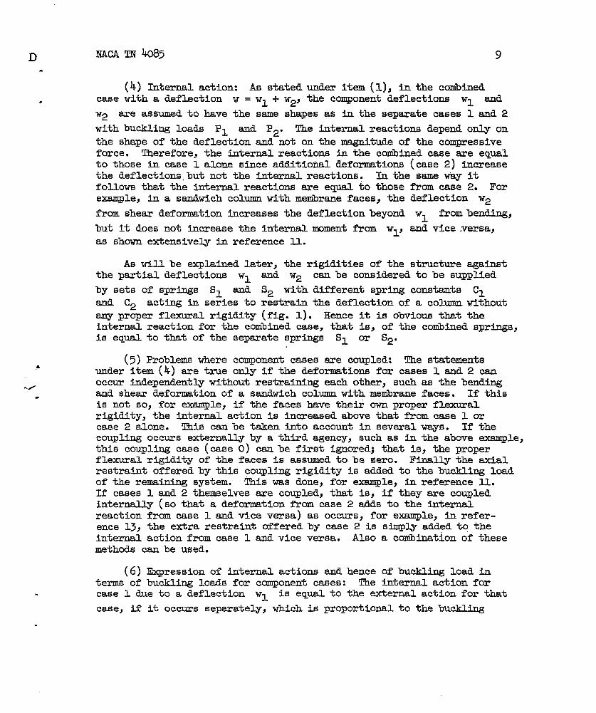
(4) Internal action: As statedcase with a deflection w = wl + w2j
9
under item (1), in the conibinedthe component deflections W1 and
W2 are assumed to have the seineshapes as in the seperate cases 1 and 2
with buckling loads P1 end P2. The internal reactions depend only on
the shape of the deflection and not on the magnitude of the compressiveforce. Therefore, the internal reactions in the conibinedcase ere eq,,lto those in case 1 alone since additional deformations (case 2) increasethe deflections,but not the internal reactions. In the ssme way itfollows that the internal reactions sre equal to those frcm case 2. Forexample, in a sandwich colm with membrane faces, the deflection W2
from shear deformation increases the deflection beyond wl from bending,
but it does not increase the internal nxxnentfrom Wl, and vice versa,
as shown extensively in reference 11.
As will be explained later, the rigidities of the structure againstthe partial deflections WI and W2 canbe considerd to be supplied
by sets of springs S1 and S2 with different spring constants cland C2 acting in series to restrain the deflection of a column without
~prqer flexural rigidity (fig. 1). Eence it is obvious that theinternal reaction for the conibinedcase, that is, of the cdbined springs,is equal to that of the separate springs s~ or s~.
(5) Problems where component cases are coupled: The statementsunder item (4) are true only if the deformations for cases 1 and 2 canoccur independently without restraining each other, such as the bendingand shear deformation of a sandwich column with metirane faces. If thisis not so, for example, if the faces have their own proper fl.exuralrigidity, the internal action is increased above that from case 1 orcase 2 alone. This can be tsken into account in several ~s. If thecoupling occurs externally by a third agency, such as in the above exemple,this coupling case (case O) can be first i~~edj that is, the properflexural rigidity of the faces is assumed to be !zero. Finally the axialrestraint offered by this coupling rigidity is added to the buckling loadof the rermining system. This was done, for exsmple, in reference 11.If cases 1 and 2 themselves sre coupled, that is, if they are coupledinternally (so that a deformation from case 2 adds to the internalreaction from case 1 and vice versa) as occurs, for exemple, in refer-ence 13, the extra restraint offered by case 2 is simply added to theinternal action from case 1 and vice versa. Also a cofiination of thesemethods = be used.
(6) Expression of titernal actions and hence of buckling load interms of buckling loads for component cases: The internal action forcase 1 due to a deflection wl is eqqal to the external action for that
case, if it occurs separately, which is proportional to the buckling

10
load’ P1 for that case
For example, for case 1
NACA TN b85
.
and can be expressed in terms of P1 and W1.
of the sandwich column considered in the section .
“Introduction,” the internal moment %1 from case 1 is eqpal to the
external moment Plwl. According to item (4) this is also the internal
moment Mi for the combined case. Hence from item (3) the equation of
external and internal moment for the combined case leads to the equa-tion Pcr
(W1+W2) ‘PIW1* Similarly, the internal moment for the com-
bined case is equal to that for case 2, which is again equal to theexternal moment for that case, giving Mi = P2W2. Equating this internal
moment to the external moment gives pcr(wl+ w2) = p2w2” E~tionof WI and W2 gives Pcr in terms of Pl and P2. If the component
cases are coupled and the latter method under item (5) is used, as willusually be done in problems where cases 1 and 2 have different boundaryconditions, the internal action will contain both psrtial deflections
‘1amd W2. Further, in such ptiohlemsthe external action is usually
expressed as ‘cr(wl + ~2) or Pm(w2 + 7W1) where T and 7 differ
from 1, so that after elimination of ‘1and W2 a more complicated
formula for Pcr in terms of PI and P2 results than for problems
where cases 1 and 2 have the same boun~y conditions.
If splitting into three different cases is necesssry the same method Pis used, equting the external actions to the internal reactions due tocases 1, 2} and 31 respectively. This leads to three homogeneous :inear \-
equations in wl~ W2, and W5. Only when cases 1, 2, and 3 have the ?
same boun~ conditions and &e not coupled or are coupled by a fourthrestraint that can be split off} as mentioned in the firs% case initem (5), does this lead to s~le formulas for Pm as expressed in
terms of PI, P2j and P3, such as those for composite columns coupled
by elastic couplings with equal spacings (ref. 6). In other problemsthis method leads to a cubic eqpation for the buckling load Per. How-
ever, by combining the first two cases and then combining them with thethird case (in ref. 13 such a case is presented, namely, the bucklingof columns witliT-sections), rather siqple end formulas could be obtainedcontaining sqgare roots only.
(7) Accuracy of method: The method leads to exact results when thedeflections Wn have the same shape, but sufficiently accurate results
can be obtained if they differ in shape, as will be shown in this report.
As shown in reference 14, if Wlj W2Z . . . Wn Uffer ~ shapej
the method remains exact if PI, P2, . . . Pn sxe considered as the

mm TN 4085
buckling loads
cases, as they
belonging to
occur in the
IL
the shapes of W1 sad W2 in the component
ccmibinedcase. Since, in general, theseare not the optimum shapes that lead to the min& bu~kling loads P1
and P2 as they occur in sepsrate cases 1 and 2, by considering PI
and P2 as the minimum buckling loads conservative results will be
obtained. However, if the structure is externally redundant, such asin the case of sandwich plates, there is another influence that may tendto make the method mconservative. This is the fact that in the compositecase the boundary and continuity conditions have to be satisfied by thetotal deflection w ordy and not by the component deflectionsWlj W2Y . . ● Wn separately. This causes a relaxation of restraints
.that tends to tie Pl and P2 smaller for the composite case than for
the sepsrate cases and thus to make the result uncon.servative. Hence insuch a case the method m.y slightly overest~te the buckling load Pa
for the coribinedcase.
(8) Problems where buckling deflection in one i.ndividuslcase isarbitrary: Let the case in which the bucklhg deflection is sr?bitrarybe case 2. Then in the composite case the deflection W2 for that case ,
s;
will have the same shape as wl for case-l. This maybe understood asfollows: If during the deformation for case 2 the shape of wl and
hence the internal reaction for case 1 does not change, the internalreaction for the combined case will also be determined by the shape ofwl (from items (4) and (6)). Hence, in order to tie the externalaction eqml the internal one at each point, the total deflec-
:
tion WI + w2~ and therefore W2j ~st also have the same shape as W1*
In some cases, such as that of a sandwich column with asymmetric boundsryconditions which will be considered in this report, the shape of wl for
the combined case will differ from that for the individual case 1. How-ever, also then, in order to obtain eqti external and internal moments, inthe combined case W2 will have the same shape as Wl> but the shapes of
WI and W2 will differ from that of WI in the separate case 1. Exact
results can be obtained by calculating P1 ~d P2 for the bu~li~
deflections as they occur in the composite case.
(9) COIMS or plates with initial deflections: The method may alsobe applied to columns or plates with initial deflections. Here one ofthe cases is the initial deflection with an individual buckling loadequal to zero (refs. 1 and 15).
(10) Reduction to case of columns or plates on elastic foundation:In several problems it is convenient to reduce the restraint offered in

12 NACA TN 4083
.the component cases to that given by an equivalent elastic foundation.The structure then can be considered to be without any flexural orshearing rigidity but to be laterally supported by springs arranged in .
series with as msmy component springs as the number of cases into whichits behavior is split. For”example, if there are two cases, the springsconsist of individual
PROBLEMS WHERE ALL
If all component
springs S1 and S2 (fig. 1).
C@Il?ONENTCASES HAVE SAME 10JNDARY CONDITIONS
General Formulas
cases have the same boundary conditions theresulting formula expressing the critic~ 10ad h terms of the criticalloads of the separate cases usually acquires the general form
P(
-1 -l+P-l)-1
cr =Po+Pr=Po+ P~ + P2 3 +... (1)’
where Pl, P2j . . . Pn) are the critical loads of the separate cases
and P. is the critical load that is due to the rigidity from the coupling
case. For example, for a sandwich plate P. is the critical load from
the proper flexural rigidity of the faces alone. Of course, this does Rnot apply if only one mode is considered, such as in the case of homo-geneous plates under nonhomogeneous stress distributiw and that of theultimate load of compressed plates, which is dealt with subsequently.
.
For plates where the rigidities in the X- and Y-directions differa great deal, such as corrugated-core sandwich plates, it is yossibleand often necessary to allow for ratios ‘2pl- of the component deflec-
tions which differ for the imaginery strips running in the X- andY-directions of which the sandwich plate can be thought to.be composed.This leads to a formula of the form
P(
cr=Po + Pr=Po + P#+ Pa-l +..0)(-l+p -l+p -1
)
-1W2Y+”””
(2)
Here the subscripts x and y refer to the buckling loads of the platedue to the rigidity of the X- and Y-strips, respectively, also takingaccount of the influence of the torsional moments acting on those strips.
.
.

NACA m 4085 13
.
This formula leads to accurate results for orthotropic sandwich platesand also to more accurate results than equation.(l) for isotropic sand-
. with plates with ~fferent boundsry conditions in the X- and Y-directions,such as long plates that sre clamped at the unloaded edges.
Discussion and Deri.vationof I@ation (1)
Equation (1), where in some cases PO is zerb, was derived in refer-
ences 3, 4, 6, and 11 for columns as well as for plates by applyingitems (I) to (6) ad (8). h the case of columns the actions and reac-tions considered were the external and internal moments, and in the caseof plates the transverse deflecting and restraining forces acting uponan element were compared. As stated in reference 1.1,this fornd.a leadsto accurate results if Wl, W2, . . . Wn and w have the ssme shape.
However, even if WI, W2, . . . Wn and w sme of different shapes
sufficiently =.curate results sxe obtatied. In reference 14 the sameformula was derived for the case in which WI and W2 sre different in
shape by comparing the work done by deflecting and restraining forces.It was found that equation (1) is act if in the ccmibtiedcase wland W2 have the same shape as they have in the component cases 1 and 2.
But this is obviously so only if, in both the component and the ccxibinedcases, wl~= w2j and w all have the sane shape, since then, from
items (3), (4), and (6), in the conibinedcase the distribution of thedeflecting and restraining forces will be similar. That is, if in the
. cabined case the restraining forces from case 1 are given by P1wb@(xjy)j
where @(x,y) is a definite function of x and y, for case 2 they willbe P2w~O(x,y) while the total deflecting forces willbe Pcrwm@(x,y).
Here x and y are the coordinates in the plane of the plate, Wb
and W~ are the maximum deflections from cases 1 and 2, and Wm = w + wlm2mis the total deflection.
Perhaps a better insight into the plqmical meaning of the method ofsplit rigidities may be obtained by deriving eqyation (1) by usingitem (10). Consider a long rectangular sandwich plate compressed inthe X-direction with arbitrary boundary conditions at the loaded andunloaded edges (fig. 2). According to item (1) the buckling deflection wis split into case 1, from bending, with deflections ‘1 and case 2,
from shear deformation, tith deflections W2. However, as shown in the
longitudinal section in figure 3, the shear deflection cannot occur

14 NACA TN 4085
without bending of the faces (the bending rigidity of the core isneglected). This means that in the combined structure case 2 c~otoccur without inducing a partial deformation according to case lj inother words, cases 1 and 2 sre coupled. According to item (5) one wayto deal with this situation is to split off the coupling action. Thismeans that in cases 1 and 2 the faces are assumed to have no properflexural rigidity. Since, however, the buckling deflection of the twosingle faces requires a load equal to theti,proper buckling load Poj
from item (6) their deflection in the combined case will generate emextra load P. on the plate. Hence, this load po has to be added to
that from the combined cases 1 and 2. The combination of cases 1 and 2is denoted as the reduced case. This procedure is exact if the bucklingdeflection of the single faces (case O) is similar to the total bucklingdeflection w in the combined case.
.
.
—
.—
In case 1 (deformationby bending only) the deflecting force actingon a small element H dx dy, where H is the total plate thickness(fig. 3), is
where ‘1 is the buckling load per unit width for case 1, neglecting
the proper flexural rigidity of the faces.A“
-Hence from item (6) therestraining force is
(4)
.
—
If the plate was supported by an elastic foundation with a foundation ._modulus cl the trem.sverserestraining force acting upon an ele-
ment H dx dy would be Clwl dx dy. Hence the restraint offered by the
plate in case 1 is equivalent to that of an elastic foundation with afoundation modulus (spring constant)
(5)
In general, this spring constant may be a function of x and y.
.
.

NACA TN 4085
L
similarly,by the plate in.
15
the equivalent spring constant for the restraint offeredcase 2 (shesr deformation of the core only) is
IazlC2 =-P—
2 &2 ‘2(6)
where P2 is the buckling load per unit width for case 2. Hence, ifwith the actual buckling deflection w the partial deflections WI
and W2 have the ssme shape as in the individualcases 1 and 2, the
reduced plate (without proper flexural rigidity of the faces) offers arestraint against buckling that is equivalent to the lateral restraintfrom two spring systems built in series with spring constants cl
and C2 (fig. 4(a)). Therefore, a unit latersl load per unit surface
causes a deflection
111w=%+%=% (7)
so that the equivalent spring constant for the reduced plate is
8
*
The equivalentbuckling load
Cr ‘ C1C2(
= c1-1 + C2)
-1 -1
cl + C2(8)
spring constant for case O (the single faces), with totalPos is in the ssme way
Ia2wo
co = -Po &2 ‘o (9)
Hence, if the actual buckling deflection w has the ssme shape as W.
(for case O alone), the equivalent spring constant for the actual.plateis
C=co+cr=co+ C1C2(
-1=Co+ cl + C2
)
-1 -1
c1 + C2(lo)
.
that is, the spring in figure k(b), with spring constant C, is equivalentto the spring system in figure h(a).

16 NACA TN 4085
.
A plate with a spring constant C will.buckle if for any element
a2wthe deflecting force -P — is equal to the restraining force Cwj so
.
&#that the buckling load is
PI
.-cwbcrbx2
(11).
or, from equations (5)} (6]) (9)) (lo)j and (U}>
[
a2wo/ax2 2 I 2)(’2d’3x2)WA‘cr=*pO ‘o ‘p$.j3&J+p2(34i3q}
b2wo/ax2 w ‘1P2‘Po 2 —+
a w/ax2 ‘-yo a2w/ax2 ~+p2 a2w/ax25‘1 2aw2/ax2w a2wJax2w
(rZ?).-
With the aforementioned assumption that w = Wo, the first tera to the
right becomes The spring forces in t~~ springs with constants (!1w
Po.
and C2 built in series sre
Clwi = C2W2 . (13)
so that from equations (5) and (6)
a2wJh2 P2---
a2w.lih2=5(14)
Further,
w= W+w12
(15)
.
.

NAC!ATN !@ 17
Using equations (14) and (15), in equation (12) the denominator of thesecond term to the right becomes
.
b2w/ax2 ~ + ~2 a2w/ax2 ‘1 . p‘1 2aw2/ax2w a2wJax2w
,$j+.)%+p2(+~):
( )W+w
= P2+P1 2W 1
.
.
.
=Pl+P2
Hence equation (12) transforms to
which is
The moreeqmt ion
P =Po+ ‘1P2cr PI + Pa
(16)
(17)
identical.to equation (1) with PX and so forth equal to zero.
general equation (1) can be deriv~d h the same way. Hence(1) is exact if wl and W2 differ in shape, but if in the
corposite case w. = w, wl and W2 have the ssme shape as in the
sepsrate cases 0, 1, and 2, respectively. This confirms tliederivationin reference 14. However, as stated previously, this condition can bemet only if WOJ WI, md W2 have the same sfiape.
equation (1) is exact within the limitations of thesuch as neglect of the deformations from transverseand from normal stresses Cz in planes parallel to
the sandwich plate.
In the latter case
usual assumptions,shesr in the facesthe middle plane of
Sandwich Columns With Various Boundsry Conditions
C!alc@ations of buckling loads of sandwich plates with severalboundary conditions were given in references 11, 12, and 14. In sand-wich columns or wide plates compressed in the short direction, the authorconsidered until now only the simply supported case (fig. 5(a)). Herethe deflection W1 for case 1, deformation from bending only, is a half
sine wave. The buckling deflection W2 from shear deformation alone
(case 2) is arbitrary. Hence, from item (8), in the combined case W1and W2 will both have the shape of a half sine wave. The single faces

m NACA TN 4085
(case O) will also buckle in a half sine wave, so that, from item (6),in the combined case the internal moment is increased by a sinusoidalmoment Pow, where P. is the buckling load of the faces. By adding a
load P. to the buckling load Pr of the reduced case an externalmoment Pow of the ssme smount is added, so that with a sinusoidaldeflection w equilibrium is maintained in all cross sections. Henceequation (1) is exact for this case.
In reference 23, the author’s method was extrapolated for calcu-lating the buckling load of sandwich columns that are clamped at bothends or at one end (figs. 5(b) and 5(c)). It was tound that for a strutthat is clamped at both ends equation (1) yields exact results, but thatfor the simply supported clamped case (fig. 5(c)) equation (1) gives
results that for two exsmples were unconservative by 5 and @ percent.2
This is understandable from the foregoing discussion. In theclsmped-clsmped case (fig. 5(b)) the buckling deflections W. and WI
for the individual cases O and 1 are both full sine waves and the shapeof W2 is srbitrary. Hence, from item (8) and the above discussion,
in the composite case w, W1 and W2 will also form full sine waves
so that from item (1) the present method leads to exact results. Anotherway to see that equation (1) is exact for a clamped-clamped strut is toobserve that the inflection potits B and C are (1/4)1 and (5/4)2 fromthe left end. The line of action of the compressive force Pcr passes
through these inflection points. The center part BC is in exactly thessme condition as a simply supported strut with length L = (1/2)1 andthe left and right parts AH and CD canbe considered as the right andleft psrts of such a column, respectively (fig. 5(b)). Since pcrj po>
Pl, and P2 in equation (1) also apply to this simply supparted column
with length L, this equation is also exact for the clamped-clampedCohlmn●
Consider now the clamped simply supported column of figure 5(c).For case 1 the buckling deflection is part of a sine wave, with the lineof action of the compressive force as the sxis. If the external andinternal moments ~ and Ml are expressed in terms of the distance of
the column to that axis, the equation ~ = Mi becomes (fig. 6(a))
P~wl ‘ -EsIsd2wl/dx2
This equation and the boundsry conditions are
(18)
satisfied by
P
.

W1 =Wmsiqx
19
(19)
where L is the effective length ABl of the column (fig. 6(a)). Thesame applies to WO for case O. Since for case 2 the deflection W2
is arbitrary, from item (8) in the composite case it would have the sameshape as WI and w. However, it may be easily seen that In the com-
posite case WI has not the same shape as in the separate case 1. It
is well known that in asymmetrically restrained, transversely loadedspans the distribution of the bending moments is changed by shear deflec-tions as, for example, occurs in thin tubes or shells supported”at threeor more points. The effect of cleqing a support diminishes. From fig-ure 6(b)j presenting the composite casej it is seen that the ltie ofaction AC2 of the compressive force enibracesan engle u with the originalaxis AC of the sandwich CO-. Hence at the clsmped end C the trans-verse shesr and the shear deformation is not zero, so that, although incase 1 (fig. 6(a)) the slope at C is zero, in the composite case theslope angle f3 at C is not zero. Now, considering first the reduced
(case PO = O), from the seinereasoning as given in item (8), Wl> W2)and w till have similar shapes tith respect to the line of action ofthe conqxressiveforce but different shapes with respect to WI in case 1.Hence, from items (1) and (7) and the foregoing discussion, eqution (1)is not exact if PI and P2 are considered as the buckling loads for
the sepsrate cases 1 and 2. On the other hand it willbe exact if Pl
sad P2 me the buckling loads for cases 1 and 2 as they occur in thereduced case of figure 6(b).
In the same wayas shown for case 1 in figure 6(a), in figure 6(b)the deflections WI for case 1 sre givenby eqmtion (19), so that W2
and w till also vary sinusoidally with respect to the line of actionABC2 of the compressive force Per. Since at C the elastic line of thestrut as shown by the solid curve emibracesan angle with its originalaxis AC, the effective length L for the reduced case (fig. 6(b)) isgreater, with respect to Z, thm in the separate case 1 (fig. 6(a)),where, as is well known, L = 0.72. Thereforej in the actual case PI
is smaller than it is for case 1 in figure 6(a). Since P2 is inde-pendent of shape or length, it is the ssme as in the individual case 2.In reference 23, PI from the separate case 1 (fig. 6(a)) was used inequation (1), which explains why Per was found to be higher than the
(exact value P.
)was assumed to be zero .
The effective length in figure 6(b) maybe found in a similar way,as was shown on pages 70 to 78 of reference 6 for various problems,using the Haarman method. The deflections Wlj W2, and w me measured
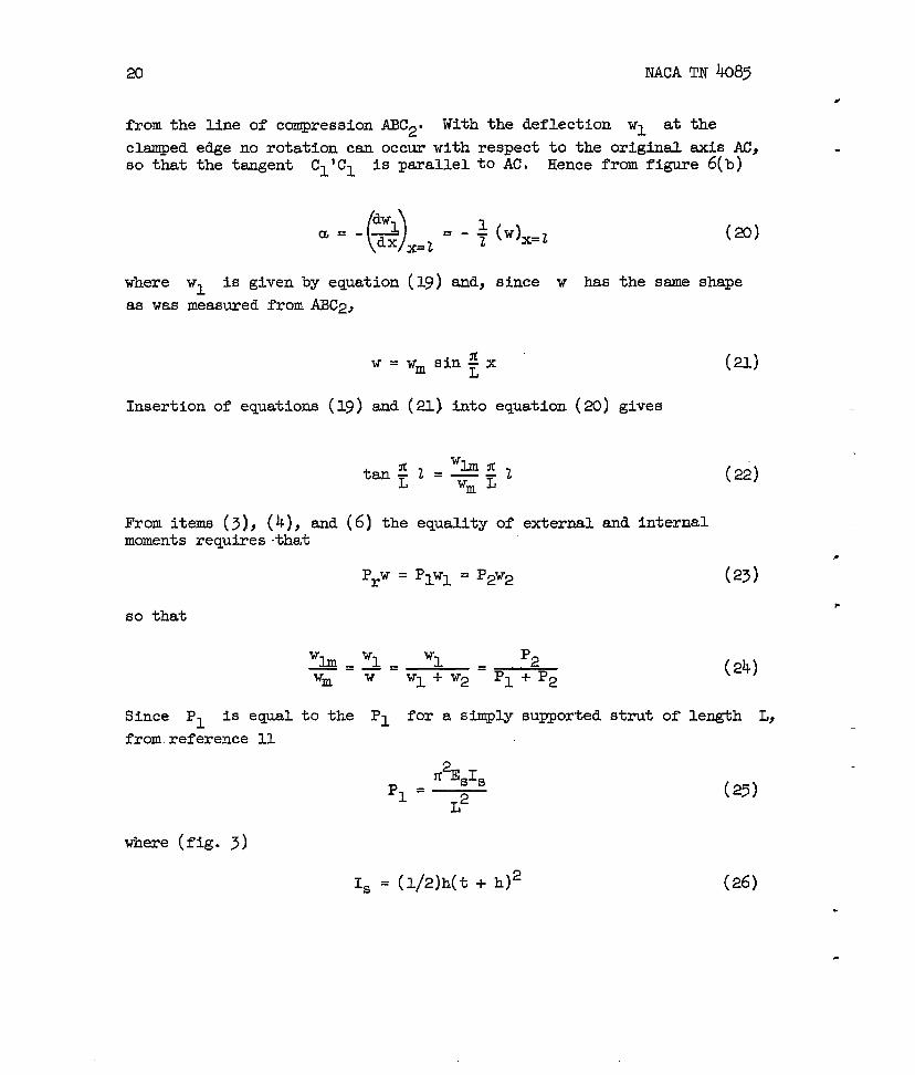
20 NACA
from the Une of compression ABC2. With the deflection WI at
clamped edge no rotation can occur with respect to the original
TN 4085
the
axis Acjso that the tangent Cl’Cl is parallelto AC~ Hence from fi~e 6(b)
u=- ()$= - + (+=~x=z
(20)
where
as was‘1 is given by equation
measured from ABC2,
w=
Insertion of equations (19) and
(19) and, since w has the same shape
WmsidxL
(21)
(21) into equation (20) gives
‘L?l3’Ctar+ ‘—d‘m
From items (3), (k), and (6) the equality of external and internalmoments requiresthat
so that
‘lm_wl= ‘1 ‘2=—Wm w WI + W2 P~ + P2
(22)
(23)
(24)
—
Since P1 is eqyal to the P1 for a simply supported strut of length L,
frcnmreference 11
.%s1s
‘1=— L2(25)
where (fig. 3)
Is = (1/2)h(t + h)2 (26)

NACA m 4085
w
and
21
(27)
where Gc is the modulus of rigidity of the core. Hence, from equa-tions (22), (24), and (25), L has to be calculated from the followingequation:
/Y&2Z L
tan Yc4= . -L
()#EsI~ z z—— +
~2 L
Then Pl and P2 follow from actuations(5)
equation (1), with PO = O and P5, . . . Pn
‘2
(28)
d (27) ad Pcr =Pr fr~
= o. with the dimensions
used in an example in reference 23, EsI~ = 43,2CKlkg-cm2, P2 = 360 kilo-
grsms, and 22=800 cm2, equation yields Z/L= 1.276, so that
L2 = 22/1.628 = 4gl cm2. Hence equation (25) gives PI = 870 kilogrsns,
so that from equation (1), with P. = 0, Pcr = 254 kilogrsms. This is. in accordance with the result obtained in reference 23 from an exact
calculation, which shows that also for columms with asymmetric edge condi-tions equation (1) is exact M applied to the correct effective length of
a the column. However, for such cases, it loses the advantage of itssimplicity.
Figure 6(b) illustrates what was said in reference 14 and underitem (7). The deflections W1 and W2 satisfy the boundary conditions
together and, as seen clesrly from this figure, ‘1does not satisfy
the boundary conditions. This relaxation of restraints causes PL to
be smaller than Pl from the separate case lalone (fig. 6(a)).
usually P. is negligible, but if the bending rigidity of the faces
is tsken into account, one simply can calculate PO in equation (1) for
the effective length L frcm equation (28),
~~sh3
P. =6(1 - V2)L2
so that from reference 11
(2?)

22 NACA TN k085
Actually this makes equation (1) s~ghtly consenative, since from fig-ure 6(b) the deflection w has a sharp break at the clamped edgel sothat PO actually will be slight~ higher than would follow from
equation (29).
Columns With Batten Plates and Latticed Columns
An application of eqyation (l).’thatshows some other features isthe calculation of the critical stress of metal columns connectedlybatten plates with equal spacings (fig. ~(a)) or of timber columns thatare coupled at equal distances (refs. 3 sad 6). In many applicationsthe deformation of the batten plates can be neglected. Then the bucklingdeflection can be split into two cases. Case 1 is caused by bending withrespect to the cormnonaxis (fig. 7(b}). Case 2 is the deformationbyshear, which bends the 8ingle coluuinsbetween the batten plates in S-curves(fig. 7(c)). These deformations can occur independently of each other, sothat
Pcr = ( -1 + P2)
-1 -1‘1
Including the plastic range, ‘1 is sufficientlyby
11% IPl=—
22
where
1 = 21C +
Here Et is the tangent modulus, h
inertia of the single columns> A iS
.-
Ah2( /4)
(30)
accurately given
(32)
is the spacing of the axes ofthe total cross section of the
composite column, ad Ip is”the moment of inertia of theIn ~ase 2 the batten pla~es translate withrotation (fig. 7(c)), so that
2#EtIcp2 =
2co
where co is the effective free length oftwo batten plates.
respect to each
(31)
8
single columns.other without
(33)
the single columns between

NACA TN k085 23
b
If also the deformation by shear and bending of the batten platesor wooden connections has to be taken into account, case 3 is added.(fig. 7(d)). However, now cases 1 and 3 cannot occur independently,since the deflection w~ for case 3 bends the single columns h a single
half wave with respect to their original axes, which is part of the defor-mation in case 1. Therefore, according to item (5), the proper rigidityof the single columnsinfluence is added in
the moment of inertia
since Ie is assumed
is first assumed to be zero and subsequently itsthe form of PO. Hence, in equation
I is that of the reduced column,
q = Ah2/4
tobe zero; P2 remains as given by
[31) for P~
(34)
equation (33).
From reference 6, assuming only the batten plates (or wooden connections)to deform, the individual buckling load for case 3 is
p3 = Ph2/cv (35)
where c is the center-to-center spacing of the batten plates and v isthe translation of the single struts with respe@ to each other per unitsheer force Q (fig. 7(d)). b reference 6 the factor p was calcu-lated for several cases. If the rigidity of the end batten plates is
. half that of the intermediate ones, p=l.
In the present problem PO is not eqpal to the buckling load of.
the single struts (in contrast to the case of a ssadwich column, whereit was eqpal to the buckling load of the faces), because during thedeflection W2 from case 2 (fig. 7(c)) no deflection in a single halfwave occurs. The bending in S-curves between batten plates causes manyinflection points to occur in the single struts, so that the internalmoment in them is not increased. If the half-wave bending of the singlestruts occurred stiltaneous3y with its total deflection w, from item (5)it would add a resistance in the longitudinal direction OZ the strut of
2~E@c/Z2. However, since this half-wave bending occurs during the
deflection w - W2 only, its curvature reduces in the ratio (W2 - w)/w,so that the added sxial resistsace is
w - W2 ti2E#cpo=——
w 22(36)

24 NACA TN 4085
similarly to equation (23)
P2W2 = Prw
so that
w- W2 P
w=1-4
‘2
and
()P 2*2%1C‘o =1-~—
P2 22
Since with a sufficiently large number of batten
(37)
(38)
(,39)
plates w, iS distrib-
uted sinusoidally and since for W2 3 the buckling’deflectionand W
at the batten plates is arbitrary, by the same reasoning as ~iven initem (8) for one arbitrary component deflection in the composite case w,W2) 3 wilJ also have a generally sinusoidal half-wave distributionand W
(actually, from ref. 24, if co = c, the centers of the batten plates sxe
situated on a half sine wave).
From item (10) the column canbe imagined as being without flexuralrigidity smd being laterally supported by a spring system as shown infigure 8. The equivalent spring constants are givenby equations (.5),(6), and (9) and by a similar equation for C3. In the same way as shown
for a spring system with spring constants Co, Cl, and C2, this leads
to an equation like equation (1) which now contains a term with P3. The
requirements of items-‘(l)and (7) for equation (1) to be exact me notentirely fulfilled here, since between the batten plates the elasticlines in the various cases sre not exactly similar, although their over-all shapes are those of half sine waves. They will be closer to thatshape, the larger the number of batten plates. Equation (1) for thisproblem is
P( )
=Po+Pcr=Po+ P1-1+P2-l+P-1-1
cr 3(40)

9
NACATN h085
where PO} Ply
replaced by Ir
25
P2, and P3 we given by eqmtio~ (39)J (31) ~~h 1
from equation (34), (33)J ad (35)= Divid@ by ‘he
cross section A gives
*2%‘m .I_Jo+cr=uo+ —.UO+
(/)Zrl?2
where Zr/r is the effective slenderness
fi2Et
%=-(/)zr2
*2%
.-.
. and
(q-1 + U2 )-l+U-l-l3
(41)
of the reduced case,
7
r2 = Ir/A = h2/k
mm eqmtions (39), (41)j ad (42)J
(42)
h shown more expensively in reference 6, equation (41) may be writtenas
fi2%“Cr=-
(45)
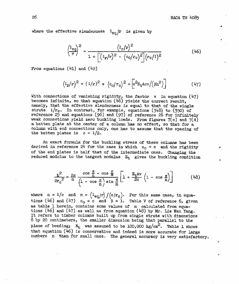
26
where the effective slenderness Zeq r is given by/
()12eq (1),2rr2—=r
[1+ (Zr/r)2 - (’olr.)q~cl’)z
From equations (41) and (42)
(zr/r)2= (z/r)2 + (.o/rc)2 +~2EtAcv/(ph2)]
NACA TN 4085
(46)
(47)
With connections of vanishing rigidity, the factorbecomes infinite, so that equation (~) yields thensmely, that the effective slenderness is equal tostruts 2/r=. In contrast, for example, eauations
v in eqmtion (47)correct result,thqt of the single(348) tO (350) of
referencem25 and equations” and {97) o: reference 26 for infinitelyweak connections yield zero buckling loads. From figures 7(c) and7(d)a batten plate at the center of a column has no effect, so that for acolumn tith end connections only, one has to assume that the spacing ofthe batten plates is c = 2/2.
An exact formula for the buckling stress of these columns has beenderived in reference 24 for the case in which co = c and the rigidity
of the end plates is half that of the intermediate ones. Changing thereduced modulus to the tangent modulus ~ gives the buckling condition
where n =
tions (46)
as table 1tions (46)
-c
l/c ma
sm.d(47)
(48)
Ill= (zq/r)/~/r.)* For this same case, in equa-
Co=c and ~ = 1. Table V of reference 6, givenherein, contains some values of m calculated from equa-and (47) as well as from equation (48) by Mr. Lie Han Yang.
.*
It refers to timber columns built up from single stfits with dimensi&s8by 20 ceritimeters,the smaller dimensi.onbehg that parallel to the
plane of bending; ~ was assumed to be 100,000 kg/cm2. Table 1 showsthat equation (~) is conservative and indeed is more accurate for largenumbers n than for small ones. The general accuracy is very satisfactory.
.

NAC.ATN 4083
Similar formulas were derived in
27
reference 6 for latticed columns.coupled by diagonals only (fig. 9(a)) or by diagonals and verticals
,
(fig. 9(b)}, using
I is replacedbyP* represents the
equation (1) with P~, . ..Pn eqyal to zero. If
Ir from eqyation (34), pl is givenby equation (Sl)j
axial resistance of the single columns, so that
(49)
In order to find P2 it is observed that for case 2, where the single
columns are assumed to be infinitely rigid against axial strain, aslope B of the column with respect to its original axis causes a trans-verse shesr force Q =P2@ that has to be resistedby the ~cing. Denoting
as Q’ the fictitious trsmsverse shear force that would cause a unitanF@ar distortion, the equation Q = Q’~
P2 = Q’
Inserting PO, PI, and P2 into equation
is obtained, so that
(50)
(1) gives
1-
As may be easily checked, for a column with diagonals
Q’ ‘~d 6in2a cos a
(50
,
only (fig. 9(a))
(52)
where Ad is the cross section of the diagonals. For the arrangementshown in figure 9(b)
l/Q’ = [/(1 E& sin2a cos a)]+ (t~ c@’%) (53)
where ~ is the cross section of the verticals. For both these casessm upper limit for Pcr is that of the single struts with a free
length c and slendernesss clrs. With diagonal cross sections ~ = 0,
equations (52) and (53) yield Q‘ = O and equation (51) reduces correctly
20 NACA TN 4085
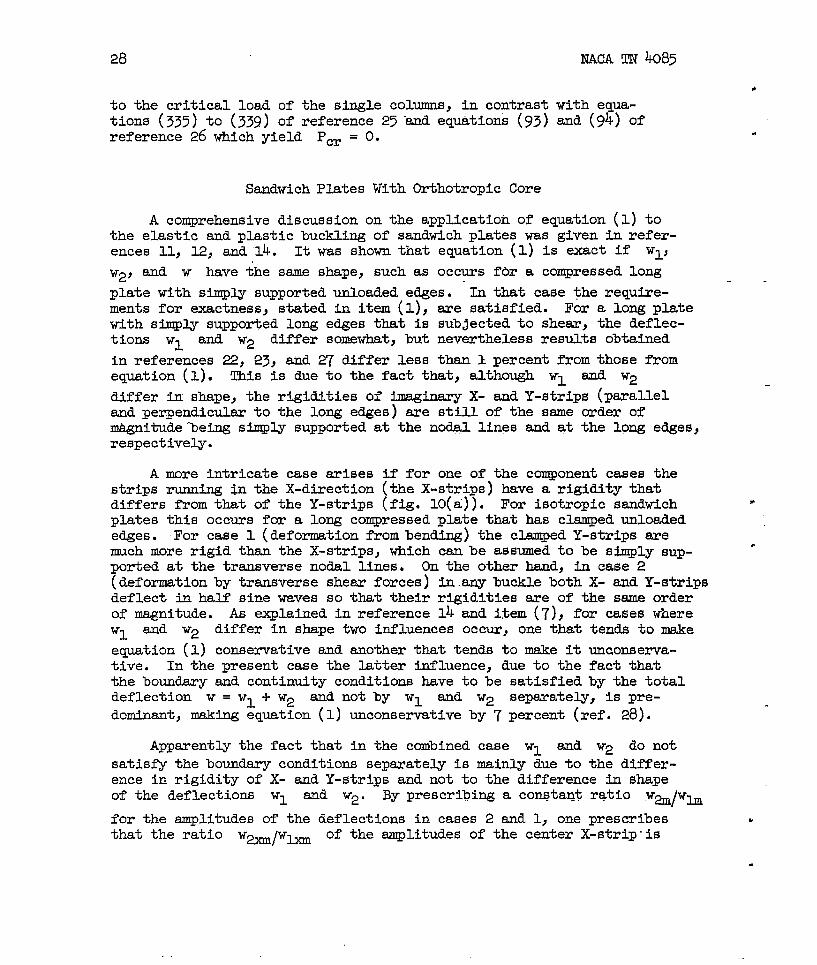
to the critical load of the single columns, in contrast with eqpa-tions (335) to (339) of reference 25-and equations (93) and (94) ofreference 26 which yield Pm = O.
Sandwich Plates With Orthotropic Core
A comprehensive discussion on the application of eqpation (1) tothe elastic and plastic buckling of sandwich plates was given in refer-ences 11, 12, and 14. It was shown that equation (1) is exact if wlj
W2, end w have the sane shape, such as occurs fbr a compressed long
plate with simply supported unloaded edges. In that case the require-ments for exactness, stated in item (1), sre satisfied. For a long platewith simply supported long edges that is sub~ected to shear, the deflec-tions w~ W W2 differ somewhat, but nevertheless results obtained
in references 22, 23, and 27 differ less than 1 percent from those fromequation (1). This is due to the fact that, although W1 aud W2
differ in shape, the rigidities of imaginary X- and Y-strips (Taralleland perpendicular to the long edges) me still of the same order ofnuignitudeleing simply supported at the nodal lines and at the long edges,respectively.
A more intricate case arises if for one of the component cases thestrips running $n the X-direction (the X-strips) have a rigidity thatdiffers from that of the Y-strips (fig. 10(a)). For isotropic ssndwichplates this occurs for a long compressed plate that has clamped unloadededges. For case 1 (deformation from bending) the clamped Y-strips arewch more rigid than the X-strips, which can be assumed to be simply sup-ported at the transverse nodal lines. On the other hand, in case 2(deformationby transverse shear forces) in any buckle both X- and Y-stripsdeflect in half sine waves so that their rigidities are of the sane orderof magnitude. As explained in reference 14 sad item (7), for cases whereWI and W2 differ in shape two influences occur, one that tends to m&e
eqution (1) conservative and another that tends to make it umconserva-tive. In the present case the latter influence, due to the fact thatthe boundary snd continuity conditions have to be satisfied by the totaldeflection w = WI + W2 and not by W1 and W2 separately, is pre-
dominant, making equation (1) unconservative by 7 percent (ref. 28).
Apparently the fact that in the combined case W1 and W2 do notsatisfy the boundary conditions separately is mainly due to the differ-ence in rigidity of X- and Y-strips and not to the difference in shapeof the deflections wl and W2. By prescribing a con&tant ratio wa/wti
for the amplitudes of the deflections in cases 2 and 1, one prescribesthat the ratio Walww of the amplitudes of the center X-strip”is

NACA TN 4085 —29
.
equal to the ratio Wmlwh of the amplitudes of the center Y-strip.
Actually in the composite case this cannot be true. If w~/w~ is.
eqti to a, w~lwm willbe much more than a because of the
clmping of the ~-strips since‘m
is slld w~ is not affected by
the clamping, as explained-previously. Hence, with a prescribed ratio
w~/w~ = W@w~ = w@w@, one could imagine that for the center
Y-strip w~ has negative end deflections -w@ md WV has positive
end deflections Wlp = w~ (fig. 10(b)). Then the boundary conditions
at y =Oandy = b are satisfiedby w = wl+wa=wlp-lr~ = o,
*ile ‘he ‘atio ‘2yal‘lya of the amplitudes of the actual deflections
‘s ‘re ‘k ‘he ‘atio ‘@#wm’ as “ ‘homd be” ‘s ‘hews ‘herelaxation of restraints for the component cases 1 and 2, which makesthe actual buckling load smaller than that obtained from equation (l).
Although for isotropic plates with different rigidities of X- andY-strips eqpation (1) is still sufficiently accurate, for sandwich plateswith anisotropic core, where the ratio
/Gy Gx differs too much from 1,
as stated in reference 14, eqyation (1) becomes too inaccurate. Fromthe preceding discussion, the obvious way to improve this situation isto admit a ratio w~w~ for the Y-strips that differs from the ratio
4w ‘b
for the X-strips. This leads to eqyation (2) that willbe. shown to give accurate results for anisotropic sandwich plates and also
more accurate results than equation (1) for isotropic sandwich plates.Equation (2) will nowbe derived..
Derivation of Equation (2)
Consider a long sandwich plate with isotropic faces, an orthotropiccore compressed in the long (X) direction, and arbitrary boundary condi-tions at the unloaded edges (fig. n). After splitting off the properrigidity of the faces (item (5)) the plate is considered as a gridconsisting of X- and Y-strips, but due account is taken of-the restraintsexerted upon these strips by the twisting moments along their long edges.This same method was applied by the author in reference ~ and in esrlierpapers for deriving simple formulas for the bending moments in rectangularplates ~der several loading and boundary conditions. From item (1) thedeflections of these strips are split tito those from %ending about thecormon middle plane (case 1) and from trsmsverse shesr (case 2).
L& the lateral restraint offeredby the X-strips in cases 1 and 2. (cases lx and 2x) and that of the Y-strips in cases 1 =d 2 (cases ly
and 2y) be equivalent to that of elastic foundations with foundationmoduli of Cws ~a~ C~~ ~d. C*Y respective~” Hence~ if in the
.

30 JWCA m 4085
composite case the deflections from cases 1 and 2 have the same shape asin the individual cases, from equation (8) the equivalent spring constantof the reduced plate is
Cr (=Cx+ Cy = C*-1 + c~ )( )q-l+ ~ -l+c -1-1
we (54)
because the resistances of X- and Y-stri.psjust act additively. Theequivalent spring constant of the actual plate which is similsr toequation (10) is
(C=co+cr=co+ Ch-l + c~ )( )-1-1+ ~ -l+c -1-1U@ (55)
where co is the equivalent spring constant-for the proper rigidity of
the faces (case 0). The equivalent spring system is shown schematicallyin figure 12. Using equations shilarto equations (5), (6), (9), (13),and (14), where the subscripts 1 or 2 are replaced by lx and ly or 2xand 2y, in a way similar to that in which equation (10) reduced to equa-tion (l), equation (55) reduces to equation (2). In equation (2) Po,
p~} p~} ‘w’and P
*tie the buckling loads for the individual
cases 0, lx, 2x, lyj and 2y, respectively. Similarly to equtrtion(1),equation (2) is exact if the component deflections Wo? w~> W2X> WQ>and w~ for these cases have the sane shape and if these shapes are
the same in the composite case as in the separate cases. Since forcase 2, for simply supported as well as for clamped edges, the X- andY-strips deflect in half sine waves (refs. 5 and 12), eqyation (2) willbe exact for simply supported isotropic or orthotropic sandwich plates,where for case 1 the deflections have this ssme shape. However, as willbe shown, for other bounwy conditions also equation (2) is very accurate(maximum discrepancy about 3 percent).
Ap@ication of Equation (2) to Orthotropic Sandwich Plates
With Simply Supported Edges
Equation (2) can be applied to orthotropic sandwich plates withsimply supported edges as follows. The restraining force exerted by anX-strip per unit plate surface canbe written as (fig. 13)
%Rx=-— ax (56)
.
—
.
.
.
.

NACA TN 4085
where Qx is theequation (102) ofsubscript 1,
31
transverse shesr per unit width of the strip. IYom
reference 30, for case 1 (bending only)l by adding the
and in the same way from equation (37) of reference 30
(57)
(58)
where N~ is the flexural rigidity of the reduced sandwich plate, and v
is Poisson’s ratio. As explained previously for the reduced case theproper flexural rigidity of the faces is neglected. The bending rigidityof the core is always negligible, so that (fig. 3)
Esh(t + h)2Ns =
2(1- VP)(59)
where Es
equationssubscript
The shear
is the modulus of elasticity of the faces (skin). From the
on page 11 of reference 31 it follows that, using again the1 for case 1,
(2
MW = -Mb _-L&Us‘-DJ-W a;; )
-$%2 by
aagles 7x and 7Y csnbe expressed in terms of the deflec-tions W* ad w~ for case 2 occurring frcm shear alone, since
obviously
(63)
——- ,,
32 NACA TN ~85
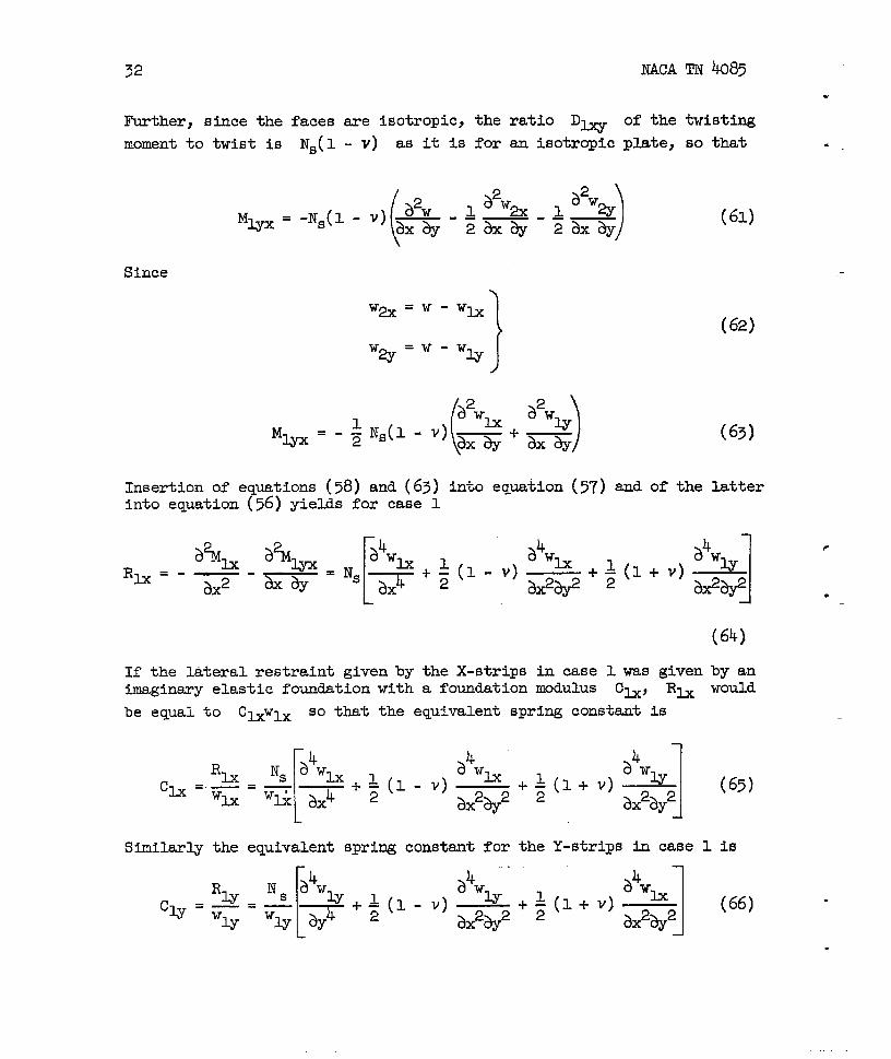
Further, since the faces sre isotropic, the ratio D= of the twisting
moment to twist is Ns(l - v) as it is for an isotropic plate, so that
(a2w )~$wa ~ a2waM-=-NS(l-V)=-–— -–—
2axay 2axay
Since
(61)
(62)
(631
Insertion of equations (58) and (63) into equation (57) and of the latterinto equation (56) yields for case 1
a%h a%wRb.-—-
ax2 &ny=Ns;4W
lx+l a4wh+:(l+V)
$wu— ~(l-v)—axh ai%# 13X2*
(64)
If the lateral restraint given by the X-strips in case 1 was given by animaginary elastic foundation with a foundation modulus Ch, Rh
be equal to Cwwlx so that the equivalent spring constant is
‘lx
[
Ns 84WU a4wh a4wuch=._=— _ ql-v) 1 l+V)w~ wfi 8X4 ‘2
—+#ax2ay2 1
ax2ay2
Similarly the equivalent spring constant for the Y-strips in case
[
4
‘1-yakww akwh
CQ.= ‘sawu 1
l-y 1
=G-+Z(l-V)=+*(l+VI —ax2ay2
would
(65)
1 is
(66)
r’
.
.
.

D WCA TN 4085 33
%
The modul.iof rigidity of the core against transverse shesz’forces~ and ~ me denoted as Gx and Gy, respectively. Rrom equa-
.tions (6) and (7) of part 1 of reference 5, ~ and ~ for case 2
.
.
can be expressed as
%x=
%=
so that, using equation (56)
‘2x 1c&=—=-—
W* Wa
Ca . % 1-—“w= ‘ZY
For aconditions
~+ 1 (67)
&&y~t
imdana.mgous to equations (65) and (66),
ah (t+h)2 % a2w2x—= - ——ax t w= &2
a%= (t+h)2 Gya2w& t
‘* *1
(68)
long ylate with simply supported unloaded edges the boundarysre satisfied i.f
Inserting this into equations (65), (66), and (68) gives
1l+; (l-v) ~+g(l+v)k
P2 e+2— ‘J
(70)

34 NACA TN 4085
~&_#(t+h)2
b2 t
~a_#(t+h)2
b2 t
where a is the half wave length in the
From figure U, since theto csrry the same load,
SO that
ex =
Similarly
ey =
Inserting Ch and C~gives
G1x-zP
‘Y
w
.
(7U
X-direction,
(72)
(73)
‘I+m C2Xw~ + w~ ‘c~+c~
w.++
‘m + ‘m Cu w
from equations (70) and
C~ and C& have
(74)
ex = L
( l+vql+rx-$+~. +~ex
)
(75)
(76)
(71) into eqyation (75)
(77)

M(!A TN 4085
●
where
.
.
.
Equation (77) can be
[
1+
FYom eqyations (70),
‘Y =
where
35
lh=t
‘x =b%x(t + h)2
written as
(>+~)r~’x+~rxey=z
(71), and (76)
1
(
l+ryl+~ J-+*&~2 ~yp2
(78)
(79)
(80)
(81)FNst
‘Y =b%@ + h)2
Equation (80) is written as
&ryeX+~2+@2+~r;ey =~2 (82)
Solving equations (79) and (82) for 13x and ey,
[( )]J32+ $2++ry - ~ ~2rx
6X =
:( )][ ( )]i1+ ~+~rx J32+ J32+~ry - (1 + v)%~y
B1 (83)

36 NACA TN 4085
●
In equation (2) p. iS the bucklti load of the faces M bu~li~ alOne
occurs, so that, from equation
‘o =
(g) on page 329 of reference 26 .
(84)
where N is the flexural rigidity of each of the faces. Furtherz inequation (2), in connection with eq..tiom (5)) (6)} (69)s and (75)>
(P* )
-1 -1 = ‘1.xp2x %x-1 + PA ‘lx = e~h (85)
PM + P= ‘cm+c*
Similsrl.y
(P~ -’)-’ = ‘Y%-1 + P2Y
mom eqmtions (5) and (69)
2Ph. >cb
a2PU=2CU
1
Hence equation (2) can be written as
Pcr = ~ (~ + $)2 ‘$ ~titi+ ‘Sly)(88)
which result could also have been obtained from equation (55) in combinationwith equations (9), (u), (69), (75)$ (76); and(~)” Using equatfon(70)Seqwtion (88) yields
(P )+7[($+1)’.+F+P2)%] (o)
23?N ~ + ~ 2 f12%Pm=- b2
—
(86)
(87)
.
*
.
.

NACA TN ko85
.
where f3x and
. this result isson of a moreFor isotropic
ex .
37
~ are given by equation (83). As stated prmiousl.y,
exact. This will be shown in the next section by comPari-~eneral formula with the results obtained in reference-32.core Gx = Gy =Gandrx=ry= r, so that tiom equation (83)
~2+l;v
ey=e= (9)~2+3j~
() ()l+~2r+M&+J3~2
2 B
and equation (@) becomes
‘m ‘$ (~+‘~(m+‘Ns) (91)
This result.cenbe shown to be identical to that given by equation (31)of reference 11 for q = 1 (elastic range).
Plastic Buckling of Corrugated Core Sandwich
or Clamped at Unloaded Edges*
—
Plates, Hinged
A cross section of the plate is given in figure 14. Consideringftist case 1 (bending only), from equation (n) of reference 33 or
< equation (22) of reference 34 the bending moment ~ from bending aboutthe middle plane of the sandwich and carried by the faces, consideredas membranes only, is
( )a2wh a2wwMu = -EsIs B —+D—
82 e
where (fig. 3)
Is =~h(t + h)2
(92)
(93)
For obtaining Mh the mament -EtcIc(~2wlJ@ taken by the corruga-
tion cross section, where *tc is the ‘tangentmddulus of the corrugation. riterial, must be added to the moment carried by the faces. Hence, using
again the ssme eqwtions from references 33 or 34,
.

38 NACA TN 40@
where
w=
and Ec is the elastic modulus of
ECIC
~
the corrugation material.
ssme references the ratio Ns(l - v) of
in the plastic rsnge changes to 2EsI~Fequation (63),
the twisting momentso that, instead of
(94)
(95)
From the
to twistthe present
(96)
The plastic pemmeters A, B, D, and F sme givenby equations (22)to (24) of reference 33 and equations (21.)or (21.a)of reference 34.using equations (94) ad (96) gives, instead of eqpation (64),
a%h $%Rb=-—-
3X2 *
from which, instead of equation (65),
(98)
.
.

NACA TN k085 39
.
In the same way,
.
using equations (92) ad (96) gives
(99).
IS the deflections now be, as was done for lateralJy loaded slabs inreference 35 and for a stability problem in reference 36>
‘3X= Yx sin :x I
where
}
‘u = Yy sin :X
J
(100)
(101)
J
Here w= and WW ace constants and the ~ are the normal functions
that automatically satisfy the boundary conditions at the unloaded edges,since they represent the modes of vibration of a Y-strip. These functionshave the general form (ref. 37)
~=+S~+ cosha#)+C2(cosa#- cosh~y+

40
so that
WCA ~ ko85
.
= %114%1
=%%mi
sxe orthogonal, %#%n Canbe
.
(103)
However, since the functions ~developed in a series of ~:
—
% = khul + kMu2 + k3mu3 + . . . (104)
It appesm sufficientlytions (101) and (104).
accurate to use only the first terms of equa-Eence
d2ul
@2(105)
—
Insertionof equations (100), (101), (103), and (105) into eqyation (98)gives
.
b
EsIs
Yx [) ‘tcA+HY
c
d%x-dY2
-(B+F)~
(106)
Similarly one obtains from equation (%)
(107)

NACA TN h085 41~Db
Instead of calculating al and k~ for various boundary conditions, it
“ msy be observed that, if one or two of the unloaded edges are eithersimply supported or clsmped, from equation (41) of reference 12, thebuckling load of a homogeneous plate is
2
[
Ph=~EI-#+P(B~2
where p and q are given in table 1
w =Ysin
1
+ 2F) + qD~2 (108)
of reference I-1. Hence, with
3X (log)a
where Y is a function of y alone, the equivalent spring constant isyanalogous to equation (5),
4aaww. 3’(2 4c = ‘ph—
[
Z EI~‘~ph=~ $41
+P(B+ 2F)%+ qD (ILO)a $
From equations (1o6) and (107) for a homogeneous plate, where ey/ex = 1-.
andw=O,.
. 4
[
~ EsIs ~ -2b~2kD
c .cb+cly=b4~4 fippa
~omparing equtions (l_l.0)and (ill) gives
1
.1%4
(B+2F)+—
1~4 D
(U)
(Ix2)

42
so that equations (106) and (107) become
NACA TN 4085
For exsmple, for clmped edges, from table 1 of referenceand q=5. From references 35 and 36 for these boundaryal = 2.365/c, where c = b/2 so that alb =“4.73. Further)kn = -o.54g84. With these values
which is in excellent agreement with the more accurateand q = 5 from equation (112).
Defining, as in reference 31, the shem_ stiffnessof shear to shear angle or
D% = Q#x
In case 2
u P = 2.5conditions~
(114)
.
values -p = -2.5 .*
‘Q%as the ratio
(115)
(116) .
.

w
.
where DQx
and D%
are given in reference 38. !I%isgives, analogous
to eqution (68),
‘QYa2%ca=-_—
‘a *
Using equation (@) this becomes
SFea.—D~z Qx
C* =~Db2 %
:
J(117)
(u8)
Insertion of the first equations in equations (113) and (D8) into equa-tion (75) yields
where
‘x =
J?EsI~
b2DQx
from which
(X20)
(X21)

44NACA TN 4Q85
“
From equation (76) and the second equatio~ in equatiom (113) and (118)
1‘Y =
{ [’l+FY qD+ ~
1; ‘
F+(B+ F)%2132 ‘Y
where
fi2E&
‘Y=—b2DQy
From equation (122)
Equations (121) and (121t)yield
(122)
.
(lz?h)
.
.
In connection tith equation (100),here as well, so that equation (2)
Pa2
cr =Po +-#
equations (85)) (86)> ad (87) app~become~, analogous to equation (88),
(Q$~ + efl~) (u6)
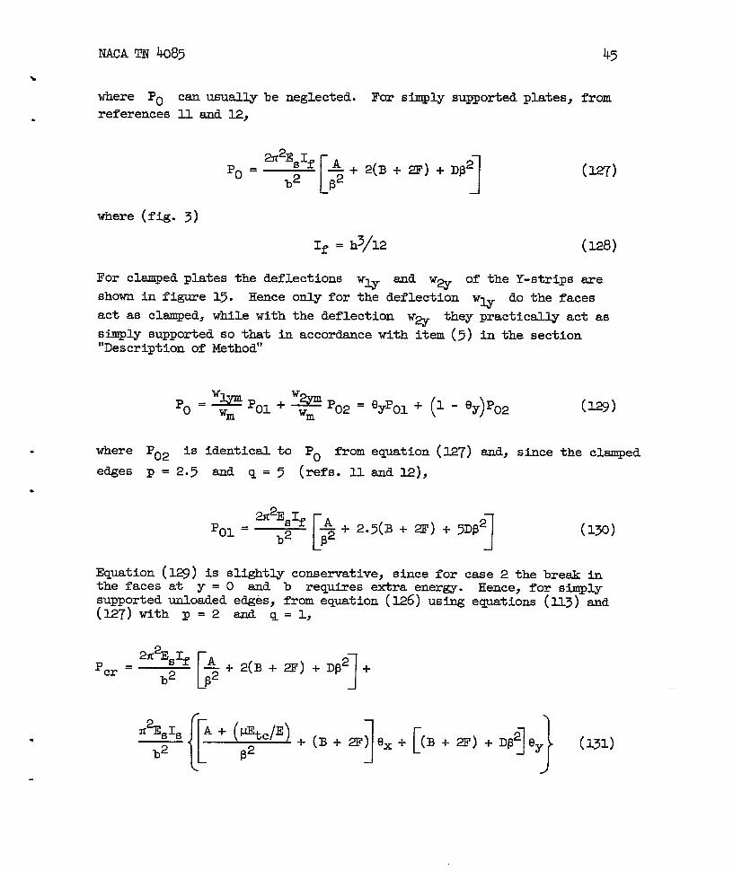
NACA TN ho85 45
where PO can usually be neglected. F& simply supported plates, from
references Xl.and 1.2,
~2EsIfp. .
[ 1
*+2( B+2F)+Dp*~2 ~ (w’)
where (fig. 3)
If . &/~ (E8)
For clsmped plates the deflections‘w
and Wa
of the Y-strips are
shown in figure 15. Hence only for the deflection w~ do the faces
act as clsmped, while with the deflection w~ they practically act as
simply supported so that in accordance with item (5) in the section“Description of Method”
zY!&02= fJypol+ (p ~y)po2Po=~Pol+ Wm (w)
‘ere ’02 is identical to P. from equation (12.7)and, since the clsmped
edges p = 2.5 and q=5 (refs. hand 12),
Equation (I..@)is slightly conservative, since for case 2 the break inthe faces at y = O and b requires extra energy. Hence, for simplysupported unloaded edges, from eqmtion (1.26)using egpations (113) and(127) with p=2andq=l,
2#Es~ *Pcr =
[~ I+2(B+2F)+Dp* +
b2
[[
#E& A + (@tc/E)
b2 p2 ][ 1}+(B+2F)ex+ (B+2F)+Dp2ey (131)

46
For clamped saudwichand (130), tith p =
NACA TN 4085
plates, from equations (~3), (126), (12’j’),(~),2.5 and q=5>
[
12E3ED_@dQ - r 1}+1.25(B + 2F) ex+ 1.25(B + 2F)+5DP2 ey~2 p2
(132)
where ex and Ely are givenhy equation (~). Besides from the
formulas in references 33 and 34 A, B, D, andF canbe read directlyfrom chwts in reference 39 as functions of the secant and tangent moduli
—
for the actual buckling s~ress Cw = Per/%.
In the elastic range, from references 33
A=I
B+2F=D=l (l-
so that for a simply supported plate equation
T
—
or 34,
~2)
—(133)
(131) reduces to..
\
(134)
where ex and ey from equation (125) with p = 2 and q = 1 reduceto
●
—

NACA TN 4085 47
.
#+*(l-v)-
‘=7++’‘x=L+ti+l-:-:( [ P2 T]p}[2+(~2++)%]-h(1— I
(135)
If the proper flexural rigidity of the faces is neglected (~ = O) andP~r is written in the form
(136)
k~ from equation (136) can be shown to be identical to k~ from refer-ence 32. With v = O, since in eqution (135) =x = 1 -
Y(( v2)rx and
F =1- v2)ryj these equations for e~, 6YJ ~d Pcr reduce to
equations (83)-and (@), so that slso these equations me exact.
For a clsmped sandwich plate in the elastic range equation (132)reduces to
21r2E#f ~Pcr =
(1- [v2)b2 ~
+2+*ey+
n2EsIs ( 1+1-V 2)
(1-2\ 2
V lb {[ (P2,
1(I+ key)~2 +
1 1
+ 1.25 ex+ (1.25 + 5p2)ey (137)
.

48
where, with p = 2.5 and q = 5, from equation (I-25)
NACA TN 4085
# + .%2 + O.*(1-v)~y -o.627&2x0==
1-V2
1+ Mb!% + ().62=j(,-‘vA B2+ 5f#+ O.*(1 - v)~
LP2 1-V2
}{ [ 1.-.$]’s
B2+[~+o.6~, +2vZx-o:@~-+ l-vry1-+
“={l+[+p+o:-q+qJ
[ 1}
6.z5iyj92+ 5p2+ 0.625(1- v)* -
l-v’ 16(1- V2)
(m)
.—
( )For isotropic core) Fx = ~Y = 1 - V2 r where r iS given bY equa-
tion (78) or (81) with Gx ~ ~’= Gc or
YT2E&
r = (1 - ~2)b2Gc(t‘+h)2
(139)
Here Gc--is the modulus of rigidity of the core. Further v = O. Thus
equations (137) and (138) reduce to
2#E&+ 2+* ey-+ (1+ 4ey)132 +
‘Cr = (1 - ,2)b2[;1
(140),
.
.
—
.
.

)NACA TN @5
.where
“
.~P2+ 0.6~(1- v)(1+ B2 r
[[ (
‘x”#+ l+s~E+o.6~(1-~)(l+p2~r+ z.kzT~+O.~l-V)~)
+ 2.5+ 5P2 #
: ~1
(141)~2- 0:25- 0.625(1- V) 1 + p2) r
( )+ 5$2+ 0.625(1- v)(l+p2)r+ 3.437’5+ 0.625(1 - v) .$ -I-2.5+ 5p2 $
It se- that the maximum discrep~cy between the simple formulasfor isotropic-ccme sandwich plates derived in reference I.1and the exactcalculation occurs for the present case of clsmped edges. lkom refer-ence 28both lead to the same buckkn loads for r = O and r= 1 andthe maximum discrepancy of 7 percent occ&rs if r is about 0.25. Fromtable 1 of reference 28 where, as usually canbe done, the proper rigidi-ties of the faces have beenstress coefficient
k=
occurs with r = 0.25 for
neglected, a minimum vslue of the buckling
b%pcr (l-#)#Fcr—=YC2NS #Es Is
(lk?)
$ = 0.6 where k= 2.88, while from refer-.ence 11 for the ssme case k = 3.08. AlSO eqyations-(lk) and (141)with If =Oforr = O and ??Z 1 lead to the same values of” k asthese given in reference 28. For the case of greatest discrepancybetween references 11 and 28, with r = 0.25, B = 0.6, and v = 0.333,they yield f3x= 0.s24, ey = 0.274, and k = 2.94, or only 2 percentmore th the exact k value from reference 28. On the other hand,“though more ac~ate, equations (lb) ad (141) me more intricate thamthe eqqations derived in reference 11. Their advsntage with respect tothose h reference 28 is that an explicit formula is obtained for Paor k. .-
For smdwich plates with orthotropic core, where as stated in refer-ence lk.the method of references 11 and E cannot be used if theratiQ Gy/Gx differs too much from 1, the present formulas lead to very
accurate results. It was shown in the foregoing discussion that forsimply supported plates they are exact. For clamped plates, in thelimiting case where rx = O and with I-L= O and ~ = O, eqmtions
.and (138) reduce to
( 137}
.

50 NACA TN ko85
‘“=(’:;”[($+‘“3”+‘1”25+“2)%-ex s
‘Y =
,2- [0.6’5~y/(1 - v)]
{p’ + [m’ + 0.625(1 - II ‘Y/(~ - ~’)]
.
(143) -
(144)
From these formulas, for example, with ~ = 1, fiy= 0.25, 1, and m,and V = 0.33, one finds that
(145)
is equal to 4.67, 2.59, and 1.45, respective. l?romfigure 4(a} ofreference 32 for p s 1 and the same values of ~y, ks is 4.55, 2.51,
.
and l.ko, respectively, so that the discrepancies ~e not more than3 percent.
●
This shows that also for sandwich plates with orthotropic core themethod of split rigidities leads to accurate results. If necessary,similar formulas can be derived for other boundary conditions.
Buckling of Homogeneous Plates Under
Stress Distribution
Nonhomogeneous
Item (6) in the section “Description of Method” can be used to calcu-late deflections of columns and plates with initial crookedness, as wasdone in footnote 2 of reference 1 and in reference 15, respectively. Itcan also be used to find the axial resistance of initially flat platesunder nonhomogeneous stress distribution, as was done in references 15and 17 for plates in the postbuckling stage. The seinemethod can beapplied for calculating the critical load for incipient buckkhg of plates,,under initially nonhomogeneous stresses. In all cases the restraining .or internal action of the plate is derived from the case of uniformly

NACA TN 4085 al
distributed stress. Hence the condition for the accuracy of this methodis that the shape of the deflection surface for the nonhomogeneous stressdistribution considered is practically similar to that under uniformstress.
Such a case occurs, for example, with buckling of a long simplysupported flange under linearly distributed stresses ax (fig. 16). ba similar way as under uniform stresses ax the bending moments ~(and Mx) will be relatively very small so that
to remain straight in the
For uniformly distributedto 0.3, from reference 40
lateral.direction or
w= Ky sin~x
the plate canbe as;umed
(146)
compressive stress with Poisson’s ratio equal
%=k~= %‘cr 0.425 = (147)
b% b%
me external and internal actions that sre compared (item (2)) are therncmentsof the deflecting and restraining forces with respect to thehinged edge. For wiform compression the deflecting forces acting upon
a small element t dx dy are -tacr(#w/i3x2) dx dy, so that frmnequation (146) they can be expressed as
D= Clacrw dx dy = Cuwy dy (148)
where C is independent of y. Hence the external moment exerted bythe forces D acting upon a cross strip b dx about the hinged edgey=o is
(149)
Then, from item (6), the moment exerted about therestraining forces acting upon the strip must be
hinged edge by the
Mi = % = * cacrb3

52
Since under nonunifomremains valid, also incompressive stresses
NACA TN 4085
compressive stresses (fig. 16) equation (146)that case Ml is givenby equation (150). With
(151)
the deflecting forces =e, analogous to equation (148), D = CUxy dy,
so that they exert a moment about the hinged edge of
% ‘JobQY dY=c Jobaxy2W II=Cue (1 - 7) obY%f+; by3wJ1o
4-T= ~ Caeb3
Since Me should be
the critical maximum
1- J
(152)
equal to Ml, from equations (147), (150), and (152)
edge stress U. is
() 4 = 1.70 f12N‘e cr ‘ ~ acr 4-T~
For T = 1 and 2 this yields k values of 0.568 andin accordanceoccurs at the
with valu=s given in referencehinged edge (fig. 17), so that
.
(153) .
0.850? respectively,46. If the maximum stress ge
‘X=a+’oand T varies between O and 1, the external
(154)
moment is
Jb b
J@J
bMe =-C 4 -37 ~aeb3
ax? Q = Cae dy-: Y3 W ‘uo 0 0

NACA TN 4085
so that ~frm eqpations (147), (lx), and (155)
() 4._. m= ML&ae cr
4.3T 4 -37 b2t
For T = 1 one obtains k = l.~0, in accordance with
53
(156)
reference 40.
Ultimate Load of Plates Under Compression
In reference 15 item (6) (section “Description of Method”) was usedfor determining the postbuckling behavior of a simply supported plate,the unloaded edges of which exe held straight in the plane of the plate,assuming the plate to remain elastic. This method wi12 here be extendedto the plastic range in order to find the ultimate load of such a plate(ref. 41).
It was shown in reference 15 that up to deflections of the orderof the plate thichess t practical exact results can be obtained byassuming the shape of the deflection surface of the p~ate to remainsimilar to that at incipient buckling, that is,
(157)
. where a = b. Considering the deflection to be developed in a Fourierseries, the distribution of the total direct stress ax in the post-
buckling range, as sketched in figure 18, will tend to superimpose on the
deflection from equation (157) partial deflections Aw = W13 sin~x sin% y,
for which the individual equally distributed buting stress Cx is
25 times that for the mode of equation (157). The stresses ay (fig. 18)
superimpose deflections sin~xsin~y snd w33sin~xsin #y,’31
with individual equally distributed budding stresses *Y that are 25
and 9 times, respectively, those connected with equation (157). Hencethe required deflect- forces for bending in these modes are much higherthan for bending in the mode of equation (157), which makes the contri-bution of these modes relatively small. In the elastic range the mem-brane stresses %x ~ in figure 18 are (ref. 15)and a

NACA TN ku85
CTm = cr-
ab = ‘W
In reference 41 it was shown that itthe same distribution in the plasticsomewhat from that used in reference
is sufficiently accurate to assumerange. Using a method that differs15 the uniform stress distribution
‘
.
Mu that is equivalent to the metirane stresses am can be calcu-.— —
latedasfO1lOws: H ‘X=(”x)u does not vary with y the work doneby these compressive stresses per buckle with deflections w is from
—
equation (157)
On the other hand the tensile stresses am from equation (158) wouldexert a work
(160)
From equations (159) and (16o) the membrane stresses tsm are equivalent
to equal~ distributed compressive stresses
()aXu= -;am (161)
The work done by uniform compressive stresses()~y u is
.
-.
.
.

NACA TN k185 55
so that from equations (15g) and (162) an equa~ distributed stiessis equivalent to a stress ‘Y
()ax u = $ FY)U = ~2(ay)u
Hence, from equations (161) and (163)shown in figure 18 is equivalent to a
() 2=axu= axe-k mxln+
the total load on the plate asuniform load
The membrane stresses a= sre caused by
~ddle strips GE due to the deflection w
so that the differenceand GH iS
Assuming, as proved to
does not vary with xstress distribution sostress
(163)
)aw-i%wn (164)
the increase in length of the
which amounts to
(165)
between the aversge direct strains in the strips AD
(166)
be true in the elastic range (ref. 15), that ax
and that Poisson~s ratio does not influence thethat it can be assumed to be zero, this gives a
o2= Esx~= = ~ E ‘m
%um 4 Sxy
where Esx is the secant modulus to be applied. Similsrly
(167)
( 168)

56
so that
NACA TN 4085
At incipient buckling therigidity of the plate srecaused by the compressive
(16g)
restraining forces offered by the bendingjust in equilibrium with the deflecting forcesstresses ax = qacrY where acr is the elastic
buckling stress of a simply supported plate (ref. 26, p. 329)
(170)
and ~ is the plastic reduction factor. The deflecting forces sre pro-portional to the center deflection Wm of the plate. Stice the restrainiWforces sre due only to the bending stresses in the plate (the menibraneforces are included in the loadings ax and ay) in the elastic range
they are also proportional to the deflecting. wm” ~erefore~ ~th finitedeflections the plate will be able to resist stresses ax snd ay
(including the menibranestresses) that sre equivalent to uniform stresses.
()ax u = ~acr (171) .
●
where fi is the plastic reduction factor of the plate flexural rigidity .at the actual finite deflection wm. Since the actual loading of the
.-
(Jplate is equivalent to u u from equation (164), combination of equa-
tions (164), (169), and (171) gives
or
a$
1 h%amxe - 4P
am--E
= ~ucrSx
k(axe - fiacr)
ahxm = 3 + (P4ESy/ESX)
(172)
(173)

)NACA TN 4083 57
““-
.
Hence from figure 18 and equation (158) the average stress, that is, $hepostbuckling stress CW, is
(174)
Apparently the postbmkling stress %depends on ~ = a/b. In general,
the value of ~ corresponding to a mini?mxnvalue of %wiIl decrease
as the deflection Wm ticreases. Howev=, as explained in reference 41,
the plate will not be free to change its wave len@h continuously becauseat a certain wave length the buckles till ~tfreeze.’lThis process can beillustratedby considering a very long plate for which any wave lengthwould satisfy the boundary conditions. For such a plate the plasticdeformation due to compressive and bending stresses will cause permanentbuckles so that after a certain stress has been reached the wave lengthbecomes fixed. IYom available test results it appesrs that the wavelength that establishes itseM at incipient buckling is =intained in thepostbuckling range. !l?heonly plates that exhibit a postbuckling stressare those that buckle in the elastic range, where at incipient bucklingP a/b = 1. Hence in eqzation (173) 13 may be assumed to be 1= ~t& case Esy/Esx ~ also be assumed to be 1.
From references 25 and 42 for simply supported plates with edgesthat sre not held straight the ultimate load is a function of the yieldstress ~ys and the critical stress am. The (average) ultimate stress
was found experimentally as
IJflt= (/)be b Cys = W-0-25”cr (175)
Assuming that in the present case, where the edges are held straight,the ulttite load is reached when the edge stresses axe reach the yield
stress, from equation (173) tith P = %y/%x = 1 and axe = Uys,
‘mm = Uys - ijucr (176)
so that the ulthte stress is, from eqyation (174)with U= = atit and
cxe = ~ys~
(177)

58 NACAm 4085
In reference 41 it was shown how for a given case ~ can be calculatedfrom the plastic deformations of the plate. Since this calculation isvery involved a direct formula was derived for ~, which for the caseconsidered was shown to be in excellent agreement with the more exactcalculation. From reference 17 for edges that sre not held straight inthe plsme of the plate, to which equation (175) refers, the mnibranestresses G& and aw are equivalent to a uniform stress
()ax u = -o.@@am (178)
Also in that case the equivalent loading of ,theplate should be equalto lam. With edge stresses ays this gives
~ys - 0.84%== ~acr
or
annml= 1.18crys - 1.18~acr (183)
Equation (174) also applies here so that, with aq = out and axe = ays,using eqmtion (180) gives
and
atit = 1ays -~%mll = 0.41aYs + 0.5gijacr (181) -
.
‘Ulti =l.7—-
aer
Insertion of a~t from equation (175)
1
0.7 ~
yields
(182)
()$
t= 1.7P - 0.423 - ().7~ (183)cr
Since ~ thus is based on test results for relatively l.mge deflections,it automatically also contains a correction on the use of equation (257)in that rsmge. In order to apply this result to the present case withedges that are held straight, it should first be determined on whichvsriables ~ depends. It is dependent on the direct stresses ax and c “
Y
.
NACA TN k085
that vary with % (fig. 18) and on the bending strains
the strain difference between both faces of the plate. Atthe buckle this dtiference is
On the other hand, from equation (166),
()l/2
2a(%)
1/2 2a %un‘m=~
=——z Esx
so that from eqyation (18k), with a = b,
From equation (170), with jl= a/b = 1,
()L11/2
t- = 0.525 ~b
so that equation (186) becomes
Hence, since ~ depends on % and A~b, it obviously
59
measured b~the center of
(184)
(185)
(186)
(187)
(188)
can be con-sidered as a function of ~ and Ucr. From equation (179)
~=o.848 h+; (189)CC??
Inserting this tito eqpation (183) gives ~ as a function of a-
and acr

60 MM TN 4085
%Xm am 1/2i = 0.25 - 0.35()
—+ o.71—cm acr
With this value of ~ for the present case, from eqpation (176),
am ays0.25 + 0.35 = -
%nRn ‘~’—= —-
()
0.71 —acr acr acr
fiOm which
(lgo)
(191)
.
“
a-—=ccr
After calculating am
tion (177).
[( )]l!’ 2-o.5k5 + 1.54%- 0.0865 (192)
acr
from equation (192), tit follows from equa-
In figure 19 ault/acr
function of aer/ay~ as thenent test results for simplyheld straight in their plane
from equation (175) has been plotted as a
dashed curve @. In the same figure perti-supported plates with edges that are not
-.
are indicated .bysquares, as plotted from ●
reference 43. The squares refer to square-tube tests by Needham (ref. 44)and the diamonds refer to V-groove tests by Anderson and Anderson(ref. 45) which are also shown in reference 43. This shows that formula ‘-(175), determined by Winter from tests with light-gage steel (ref. 42)involving plates that are not held straight In their plane, leads toexcellent results. Hence,~e formula for ~, derived from it and pre- ‘“ “sented herein as equation (190), can be considered as well based. There-fore the combination of equtions (177) and (1$2) can be ewected toyield satisfactory results for plates with simply supported edges thatare held straight in the plane of the platee In figure 19 ~~t/acr
from these equations has been plotted against/
acr ays as the solid
curve @; the test results from Botman (ref. 46), as given in refer-
ence 43, are indicated by triangles. These tests were done with three-bay plates between knife edges so that the edges were not held completelystraight. The test results should therefore be located between the
—.—
curves @ and @, which indeed occurs. The theoretical results from
reference 43 for plates with edges held straight are indicated by circles.These are a little above curve @. This maybe because inreference~3 - - —
Poisson’s ratio was assumed to be 0.5 for plastic as well as elastic .
deformations which increase the plate rigidity above its actwl value.Hence eqmtions (177) and (lgp) yield reliable results.
-.

NACA
ence
TN 4085 61
Formulas based on the same principles have been derived in refer-41 for the ultimate load of stmply supported and clamped plates
under the additional influence of thermal stresses. Also formulas werederived for the equally distributed stresses ()ax u and
()ffyu ‘itare equivalent to arbitrarily distributed thermal stresses ax and Cy
as fer as critical as well as ultimate loads are concerned.
PROBLEMS WHIRE COMPONENT CASES HAWE DIFFEMNT BOUNDARY CONDITIONS
Problems where the component cases have different boundexy condi-tions have been dealt with in references 13, 16, 17, 18, and 19. Aspointed out under item (6) these problems lead to more intricate relationsbetween Pa and Pl, P2, . . . Pn than those where the boundsry condi-
tions for all cases are the ssme. A simple example is’the ~roblem ofdetermining the buckkn stress of an I-section about its minor axis.The buckling deflection of the cross section is shown in figure 20(a) andis split into case 1, a deflection as a column without distortion of thecross section (fig. 20(b)) and case 2, a distortion of the cross section(fig. 20(C)). This poblem was dealt with extensively in reference 13where the deflecting and restraining forces were chosen as the externaland internal actions. This method was sufficiently accurate becawe thedecrease of the colunm buckling stress U1 (case 1) or plate buckling
. stress ff2 (case 2) from the interaction of cases 1 and 2 was only a
small fraction of the actual buckling stress.
.Somewhat more accuracy can be obtained by comparing the work done
by deflecting and that done by restraining forces. This”method was usedin references 17, 18, and 19. It will be demonstrated here in derivingthe buckling stress of stringer panels.
The stringer panels considered are supportedby stiffeners of eqyalcross section and located at eqml distances b (fig. 21). The half’wave length of buckling in the X-direction is denoted as a (fig. 22(b)).If no stiffeners were present, the buckling deflection of the plate wouldvsry sinusoidally in the X- and Y-directions. If stiffeners are presentand the deflection WI (fig. 22(a)) which determines the deflection of
the stiffeners vsxies in the same way,
-tux(a%lax2)per unit plate surface,
sive stresses ax which the panel can
will as a whole vsry sinusoidally too.
if the restraining forces EI(d4w/dx4)
the additional deflecting forces
caused by the additional compres-
sustain due to the stiffeners,
Hence, equilibria is possible
per unit length suppliedby the

62 NACA ‘IN4085
stiffeners also vary sinusoidally in both directions. This is indeedthe case if WI vmies sinusoidally. Hence, it may obviously be assumedthat
W1 =whsin~ %in*=Y1 sin Ax (193)
where
A = 7t/a (194)
In a similar way, as was done in reference 13 (fig. 20) for deter-mining the interactionbetween column and plate buckling, the bucklingdeflection of the panel (fig. 22(a)) could nowbe split into two cases,and the buckling stress Ucr expressed in terms of the individualbuckling stresses for these cases. In the present case a slightlydifferent approach is used by first splitting off the.buckling stress aOof the unstiffened sheet, caused by its buckling into the shaye WI from
equation (193) and denoted as case O, as indicated by the first methodunder item
where
and ~ iSdeflection
(5). From page 329 of reference 26,
(195)
P = a/b (196)
the flexural rigidity of the sheet. The resulting bucklingof the reduced structure with buckling stress crr= Ucr - Uo,
.
.
where consequently the partial buckling stress U. caused by the rigidity
of the sheet against bending into the shape W1 is neglected, is then
split into two individual cases. Case 1 is the deflection wl~ shown
separately in figure 22(c). Case 2 is the extra deflection W2, shown -.
separately in figure 22(d), which is caused by the deflecting forces acti~”—
on the sheet and created by the partial buckling stresses ar = acr - U.
that cannot be t&en by the unstiffened sheet. These deflecting forcessme consequently resisted.by the stiffeners,which cause the bending ofthe sheet into shape W2 like a laterally loaded continuousplate onseveral supports.
.
●
NACA TN @35
Hence, the actual buckling stress of the panel is
63
where crr has
the individual
Since the
~cr=(Jo+ar (197)
to be expressed in the buckling stresses cl and U2 for
cases 1 and-2, respectively.
flemral rigidity of the sheet has to be neglected here.in case 1 the buckling str=ss i~ is due to the flexural rigidity ~f-~hestiffeners alone. The critical thrust of the single sttifeners, witheffective moment of inertia 1, is
/% = fi2EIa2 = h2EI (198)
Hence, the restraining force RI acting on em element of length dx of
a stiffener if bent into a ha~ sine-wave is equal to the deflecting
force D1 = (J-PI ~2w &#) dx or, from equation (193),
Rl=Dl= A+lwl
At incipient buckling of the complete panel
dx (199)
the compression Astcm in. the stiffener itself, with cross section Ast, causes a deflecting force
so that the restraining
RI! =
Therefore, by comparing
(200)
force exertedby a stiffener on the sheet is only
RI - Dst = X2(P1 -)‘fitUcr‘1 a (201)
equations (199) and (201), the restraining forceexerted by a-stiffener on the sheet is equal to that exerted by a stiffenerwith a zero cross
,The buckling. nay be written in
.
section and a critical thrust
PI ‘ = pl - Astuw = 1% - A#cr (202)
stress for buckling in a sha2e like that in figure 22(d)general as (ref. 25)

64 NACA TN M85
where the computation for p and q is given in the appendix. However,since only the reduced case is considered, where the part aO from eq..-
tion (195) for buckling in a shape like W1 must be ignored, the criticalstress for the present case 2 is
CL21= ap - 00 -=~-:+(.-j)+p (2O4). k,, ~
In order to express the reduced critical stress ar of the coribinedstructure in terms of P1’ and U2’ from equations (202) and (204), the
work done by the deflecting and restraining forces will be compared. !Ihedeflections W1 and W2 in figure 22 both--varysinusoidall.yin the
X-direction (fig. 22(b)) so that, simih to equation (193),—
= Y2 sin Ax (205) -W2
where Y2 is a function of y alone. Hence, at the reduced buckling—stress the deflecting force in the Z-direction (fig. 22(a)) exerted on .a sheet element t b dy as a consequence of the deflection w =W1+W2
,is -tar(~2w/~x2) dx dy or, from equations (193) and (205), s
D .&r@1+w2) tidy (206)
Since from figure 22(a) the deflection W2 does not involve wdeflection of the stiffeners, it is evident that the work done by thedeflecting forces for the deflection W2 is taken entirely by bending
of the sheet in the shape w2. Furthermore, since the reduced case is
considered, where the flexural rigidity of the sheet is ignored for theshape WI, the work done by the deflecting forces for the deflection WI
is tsken by bending of the stiffeners alone.
The deflection wl win be considered first. Denoting the deflec-
tions of the stiffeners as
Wst = wstm sin ~ (207)

)
.
.
mm m? Lu85 65
where Wst = Wl, from equations (201) and (202) the restraining force
exerted by a stiffener per length
R1’ =
From the foregoing discussion the
a
dx is
Aywst dx (208)
work done by the deflecting forces Dfrom eqyation (~6) for the deflection W1 has to be eqti to the totil
negative work done by the restraining forces RI’ from eqyation (208)furnished by the stiffeners. Hence,
or, using equations (.206)and (~8) and dropping the terms %/2,
where the double inte~als have to be extended over the entire sheet withdimensions a times
. stiffeners. Eqyation
and, since Wst =W 1
“rib and the summation sign refers to the (n - 1)(209) my be written in the form
we indicated in figure 22(a) snd where
(fig. 22( a)), using equation (193) gi~es
i=n-1
(210)
(211)
66 NACA TN k85
.Hence equation (210) transforms to
=0
where, from equation (~2),
P. ‘
K .!ikbt
(213) “
(214)
(215)—
(216)
Replacing al‘ in equation (213) by the last term of equation (214), in
which again Ucr is expressed accordiag to equation (197), equation (213)becomes
[ .( g(1+ 03r- u~- Kcro w~+qarw~=o
●
(217) ‘
L
In order to obtain a second relation between Ww and w~ the workdone for the deflection W2 is considered. In case 2 buckling occurs
at the stress a2’ from equation (204), so that the restraining force
R2 t dx dy is equql to the deflecting
actiWflt~~~q;#) dx dy = h2ta<w2 dX @.force D2 ThifIrestraining
force R2 depends on the deflection W2 alone and not on the compressive ‘–
stress so that, with the assumption that in the combined case the deflec-tion w2 has the same shape as in case 2, also in the combined case the
restraining force is
R2 . 12ta2’w2 * Q
.
.

NACA TN 4085
%
Ecyzatingthe work done for* from eqpation (206) to the
from equation (z18) gives
. PP
the deflection W2 by the deflecting
negative work done by the restraining
nfi
67
forces D
forces R2
& J %~dY=$Jp2w2~dY2
Using equations (206) and (=8) and dropping the terms A2/2, thisbecomes
J J~22 &dy=tc2’tar W1W2 dx dy + tar
JW22 dx dy (~9.)
or
( )7drw~+ Ur - U2’ w~
where
J!!W1W2 ax @
7‘a=—
J‘lm W22 & @
(220)=0
(221)
The buckling condition is obtained from the two homogeneous equa-tions (217) and (220) by equating the denominator determinant to zero,which yields err,so that from equation (197)
acr =Cro+ar
[{ 1)1/2
al -Kcro+(l+K)CQ~ h(l-7q+d(U1-~ao)U2’=a+
o1- 1-
2(1-7P+K)[ 1
2U1- Iwo+ (l+ K)C21
(222)

68
or
NACA TN 4087
where
k =k +1+~(1+~)cr o 2(1 - 7T + ~)
a = kcr ficr b2t
.
(223)
(224)
o‘ %’/(%- %)and from equations (195), (204), (215), and (216)
%K ‘x
(=5)
(226)
●
b
The values of p, w and yg for the cases of 1, 2, 3, and an infinitenumber of stiffeners are determined in the appendix and are assertibledin table 2. If kl = Oand~= O so that no stiffeners are present,
equation (224) reduces to &-r = ~Y as it should be. If %: and
thus S1 are infinite, so that no interaction occurs, equation (2!24)becomes
k [@+~r+.j=lcr =
(1+ K)(=7) “
.

69NACA TN 4Q85
in accordancebe used if ~
with equation (1) of reference 47. Equation (227) may> 8. The lsrgest interaction occurs for small.values of p.
.In table 3 the results from equation (224) for P = 1 axe compared withthose scaled from the graphs of reference 47. The values from refer-ence 47 for kcr > 4 refer to the extension of the EI/(bli) curves.
The only importad discrepancies occur for n = 3, EI/(bN) = 0, and0, where the value from reference 47 is placed within parentheses,
~i;ce here indeed from equations (224) and (226) kcr = ~ = lw/81 = 1.235
so that the graph seems to be inaccurate at that point.
The interaction is the smaller the larger the value of Q is fromequation (225). In a similar way as was done with equation (@) of refer-ence 13, for not-too-small values of O equation (224) maybe simplifiedby observing that the term in the large parentheses maybe written as
1- ((1-.)1/2=1- 1+ -~.a)=~++p) (=’8)
since in that case ction (224) transforms
is small with respect to unity so that equa-to
kU=kO+ Q* l+Q(l+K}
[ 1‘+& : ?::$ (’1 -‘) ‘-)
. For still larger values of 0, the term 1 in the denominator of thefraction within the large brackets may be neglected, so that equation (229)becomes
k
[ 1
=~+Q+l-7q+K‘1-%
cr(1+ K)2 l+ Q(l+IC)
(230)
Equations (~ ) and (230) are sufficientl.yaccurate if Q is largerthan 1 aud 4, respectively.
Values of kcr may be calculated directly from equations (224),(229), or (230). They have to be calculated for half wave lengthsa = 2/m, where Z is the simply su~orted length of the panel in theX-direction (fig. 1) and m is an integer (for only an infinite numberof stiffeners can a be assumed to be equal to 2). The lowest valueof kcr so obtained has to be inserted into eqution (223). The
.effective moment of inertia I of the stiffeners to be used in

To NACA TN 4085
equations (226) for calculating kl has to be determined as shown in
reference 20, where also a formula for the buckling stress coefficientfor forced crippling is derived from equation (22k).
.
This example shows that the method is applicable and gives accurateresults for very intricate problems as is shown also by its applicationin references 13 and 17. The present problem was also worked out forstresses
aYacting simultsmeousl.y in a direction perpendicular to the
stringers as msy be caused by thermal stresses, but it was thought thatomission of the stresses aY
gives a clesrer picture of the method.—
It should be noted that in reference 13, where the deflecting andrestraining forces acting upon an arbitrary small element were chosenas the external and internal actions} these forces were e~ressed interms of the maximum deflections w, Wl, and W2 to which they were
proportional. In the present case, and also in reference 17, where thework done by the deflecting and restraining forces was considered, theforces acting upon all elements must be tsken into account. These forcescannot be expressed in terms of the maximundeflections, since for dif-ferent elements different proportionality factors apply. Therefore theywere expressed in terms of the local deflections W> Wl, and W2 of
the individual elements, which expression in all cases considered wasfacilitated by the sinusoidal variation of the deflections in the X-direction by which the deflecting forces -tax #w/c3x2 are proportional
to w.
Since references 13 and 17, where the method was applied to severalother cases with different boundary conditions of the component modes~are directly available, it is thought unnecessary to give other examples.The reader therefore is requested to consider references 13 and 17 aspart of this section.
Cornell University,Ithaca, N. Y., June 28, 1956.
—
.

NACA TR k085 71
.
.
APPENDIX
COMPUTATION OF p,
computation of p and q
q,myp
in Equation (203)
For n = 2.- For plates with one stiffener (fig. 23(a)) in case 2(fig. 22(d)) each plate of width b can be considered as sim@y supportedat one unloaded side and clsmped at the other one. From reference 48for the clamped simply supported case p = 2.27 and q = 2.45.
For n = 3.- For plates with two stiffeners (fig. 23(b)) plate ABis simply supported at edge Awhile at B it is subjected to a momentthat vsxies sinusohilallyin the X-direction. Plate EC is subjected toequal and opposite sinusoidal moments at edges B and C!. The bucklingcoefficient ~ can be determined by requiring that the spring constant
against rotation of plate AB along B is equal and opposite to that of Walong B. Spring constants for these cases or rather the specific aaglerotations were derived in reference 49, where they are given by equa-tions (~), (52), (53), and (54). The same results were obtained inreference 50 and sre presented in tables in reference 51, where the
stiffnesses Sm and SN are the quarter spring constants referringto the present plates AB and BC in B. Hence, ~ is determined by the
condition S1l = -Sm. It appesrs that the minimum value of k2 occurs
for ~ = a/b = 0.72 and is equalto 6.15. From equation (6.4.1) ofreference 25 this minimum is
(%)min=pInserting the value 6.15 into equation
+2@ (Al)
(Al) and kp = 6.935, obtained forB = 1, into equation (203), one obtatis p = 2.36 ‘and q= 3.58.
For n= 4.- In the case of n = 4, (fig. 23(c)), from symmetryplate BC can be considered as clamped at edge C so that, with the nota-tions of reference 51, the condition at B is S~ = -S, yielding aminimum value of ~ = 6.47 and, for 13= 0.9, k2 = 7.00. From equa-
tions (Al) and (203) this results in values of p = 2.37 and q = 4.20.
For n = m.- For the case of n = m all plates can be assumed tobe clamped at both edges (fig. 23(d)) so that, from reference 25, p = 2.5and q=5. Values of p and q are assembled in table 2.

72 NACA TN 4085
Computation of 79
From equations (211), (193)) and (205))
7‘al=—WM
mom equation (193)I
Y1=Wbsi+
while from ecpation (624) of reference 25 forgeneral,
(A2)
(A3)
(Ak)
the plates considered, b
‘2= c1 cosh aly + C2 sinh ~Y + C3 cos a~ + C4 sin a# (A5)
where
[ 1
l/2
*A2 + x(ta/N)1/2
%’U2 =
while X is given by equation (194).
(A6)
For n = 2.-of simple supportequation (A5)
Considering plate AB in figure 23(a), the conditionsat y = O require that cl = C3 = o so that from
Y2 = C2 sin aly + C4 sin a~ (A7)
At y=b, Y2 = o so that from equation (A7)
(A8)
)D NACA TN 4085 73
From table 26 of reference 25 the buckling coefficient k for plate ABin figure 23(a) (one
. occurring for a half
Hence, from equation
and ~ = 1.165fi/b.
edge, S-&ply support~dj the other, ftxed) % s.k2,wave length a = Bb = 0.8b so that in eqyation (A6)
ta/N =lm2/1)2= 5.@#jb2
(A6), with A = fi/O.8b,one obtains al = 2.12K/b
Inserting this into equations (A7) and
Y2. C2~inh(2.12bqy/b) +790 sin(l.165my/b)]
Denoting the deflection at y = b/2 as w~, this becomes
.- —Y2 = ~~inh (2.12zy/b) + 790 Eti (1.16%ry/b)l
779
From eq-tions (A4) and (A9) one obtains
IbY22 dy = 0.k71bww2
o
Jb
Y1Y2 dy = 0.366bwhw~o
(A8)
(A9)
Hence, from equations (A2) end (A3) q = 0.732, 7 .0.778, ~d7T = 0.57.
For n = ~.- It is sufficiently accurate to calculate ~ ad 7for n = 2andn=w only and to derive from these values the valuesof ~ and 7 for intermediate n values. For infinite values of n(fig. 22(b))
Y~ . Wh = Constsat
Worn symetry (fig. 23(d)) equation (A5) transforms
Y2 ‘ Cl cosh~y+ C3 COS a~
(A1O)
to
(All}

NACA TN h08574
Aty= b/2, Y2 = O so that from equation (All).
C5 = -cl
From table 26 of reference 25 thefor ~ = &/b = 0.668, from which,one obtains
%=
‘2 =
cosh(~b 2)
+ (COS ~b/2
(Au) “
buckling coefficient k = 6.97 occursin a ~ shilsr to that for n = 2“j”
2.488@
1.303Jf/b
= ~~Od2.~b/d + 54D5 COS(103033w/b)]~2 .
Hence, from equations (AIO) and (A13)
(A13)
o.5bwh2
J- Y2~ dy = o.2065bwa2o
Jb/2
J
b/2Y1Y2 dy = w= Y2dy= o.27bwdwa
o 0
so that from equations (A2) and (A3) ~ = 0.54, y = 1.31, and y~ = 0.707.
For n = 3.- It is sufficiently accurate to consider the anglerotations at B and C (fig. 23(b)) to be zero so that the two outerPlates AB and CD for n = 3 are similar to the Plates for n = 2(fig. 23(a) =d the center-plate is similar to those forof n (fig. 23(d)). Hence, as an average value
m =; (0.57+0.707+0.57) =0.616
infinite values
.

NACA TN 4085 75
For n = 4.- Assuming the angle rotations at B, C, and D to be zero(fig.~ne obtains, for n =4,
~=3(0,57+0.707) =0.639
Values of w are assembled in table 2.
.

76 NACA TN 4085
.
REFERENCES
1. Bi,llaard,P. P.: Knikzekerheid van den
.
bovenrand van open wandbruggen(Safety Against Buckling of the Top Chords of Pony TYusses). DeIngenieur (The Hague, Ho~~d), Nr. 4~.1932”
2, Bi~laard, P. P.: Nauwkeurige berekening van de plooispanning vamhoekstalen, zoowd voor bet elastische als voor bet plastischegebied (Accurate Computation of the Buckling Stress of the Legsof Steel Angles in the Elastic as Well as in the Plastic Range).De Ing. in Nederlandsch-Indi~, Nr. 3, 1939, pp. 1.35-1.45.
3. Bijlaard, P. P.: Berekening van de knikspanning van gekoppeldeprofielen volgens een nieuwe methode (Computation of the BucklingStress of Built-Up Sections Connected.With Batten Plates by a NewMethod). De Ing. in Nederlandsch-Indi&, Nr. 3, 1939, pp. 1.4~-l.46.
4. Bijlasrd, P. P.:” On the Elastic Stability of Thin Plates, Supportedby a Continuous Medium. Verb. Koninklijke Nederlandsche Akad.W~tenschap~n,
5. Bijlaard, P. P.:Pts. I and 11.vol. L, nos. 1
6. Bijlaard, P. P.:
vol. XLIX, no. 10, 1946,pp. 1189-1199.
On the Elastic Stability of Sandwich Plates.Verb. Koninklijke Nederlandsche Akad. Wetenschappen,and 2> 1947, ~. 79-87, 186-1930 w
Some Contributions to the Theory of Elastic and
—
Plastic Stability. Pub. Int. Assoc. for Bridge and Structural Eng.(Zlirich),VO1O 8, 1947, pp. 17-80.
*
7. Bijlasrd, P. P.: On the Torsional and Flexural Stability of ThinWalled Open Sections. Verb. Koninklijke Nederlandsche Akad.Wetenscha~en, vol. LI, no. 3, 1948, pp. 314-321.
8. Bijhsrd, P. P.: Stability of Sandwich Plates. Jour. Aero. Sci.(Readers’ Forum), vol. 16, no. 9, Sept. 1949, pp. 573~574.
9. Bijlaard, P. P.: AnalYsis of the Elastic and Plastic StabilityofSandwich Plates by the Method of Split Rigidities. PreprintNo. 259, Inst. Aero. Sci., Jan. 19’30.
10. Bi~laard, P. P.: Stability of Sandwich Plates in Combined Shear andCompression. Jour. Aero. Sci. (Readers’ Forum), vol. 17, no. 1,Jan. 1950, p-:63.
11. Bijlaard, P. P.: Analysis of the Elastic and Plastic Stability of .
Sandwich Plates by the Method of Split Rigidities - I. Jour. Aero.sci., vol. 18, no. 5, May 1951, PP. 339-349*
.

N4CA TN k085 77
.
U. Bijlasrd, P. P. : Analysis ‘ofthe EUstic and Plastic Stability ofSandwich ~lates by the Method of Split Rigidities - II. Jour.Aero. Sci., vol. 18, no. 12, Dec. 1951, pp. 790-796, 829.
13. Bijlaard, P. P., and Fisher, G. P.: Interaction of column andIocal Buckling in Compression Members. NACATN 26k0, 1952.
14. Bijlaard, P. P.: Analysis of the Elastic and Plastic Stability ofSandwich Plates by the Method of Split Rigidities - 111. Jour.Aero. Sci. (Readers’ Forum), vol. 19, no. 7, July 1972, Pp. 502-503.
15. Bijlaard, P. P.: Determination of the Effective Width of PlatesWith Small Deviations From Flatness by the Method of SplitRigidities. Proc. First U. S. Nat. Cong. of Appl. Mech. (June 1951,~iC~O, Ill.), A.S.M.E., 1952, pp. 357-362.
16. Bijlaard, P. P.j and Johnston, G. S.: Compressive Buckling of PlatesDue to Forced Crippling of Stiffeners. Pts. I and II. S.M.F. FundPaper No. FF-8, Inst. Aero. Sci., Jan. 1953.
17. Bijlaard, P. P., and Fisher, G. P.: C!olumuStrength of E-Sectionsand Squsre Tubes in Postbuckling Range of Component Plates. NACAT!N2994, 1953.
18. Bijlaard, P. P.: Analysis of the Buckling of Stiffened Plates,Having Any Number of Stiffeners. Rep. No. 02-98k-013, Bell AircraftCorp., July 1953.
19. Bijlaard, P. P.: Buckling Under Ekternal Pressure of CylindricalShells Evenly Stiffened by Rings Only. Rep. No. 02-941-~2, 13ellAircraft Corp., May 21, 1952.
20. Bijlaard, P. P.: On the Buckling of Stringer Panels ticluding Forcedcrippling. Jour. Aero. Sci., vol. 22, no. 7, July 1955) pp. 491-501.
21. Schmitt, A. F.: The Buckling Effectiveness of IXmbler.ReinforcedSheet. Proc. First Midwestern Conf. on Solid Mech., College ofEng., Univ. of 111., 1953, pp. 11-13.
22. P1.antema,F. J., and DeKoc@ A. C.: The Elastic Overall Instabilityof Sandwich Plates With Simply Supported Edges. Rep. S. 346,Nationaal Luchtvasrtlaboratorimn (Amsterdam), 1949.
23. Plante-, F. J.: Theory and Experiments on the Elastic OverallInstability of Flat Sandwich Plates. Rep. S. 402, Verslagen enVerb., Nationaal Luchtvaartlaboratori~ (Amsterdam), 1952.
.
78
24.
25.
26.
27.
28.
3*
30.
31.
32.
33●
34.
35’*
NACA TN 4085
Bijlaard, P. P.: Khikzekerheid van door koppelplaten verbondenprofielen (Safety Against Buckling of Built-Up Sections Connectedby Batten Plates). De Ingenieur (The “Hague,Feb. 17, 1933, pp. 31-36.
Bleich, l%?iedrich: Bu6kling Strength of MetalMcGraw-Hill Book Co., Inc., 1952.
!l?imoshenko,S.: Theory of Elastic Stability.Hill Book Co., bC., 1936.
Holland), Nr. 7,
Structuresj First cd.,
First cd., McGraw-
Seide, Paul: Shear Buckling of Infinitely Iong Simply SupportedMet.aliteType Sandwich Plates. NACA TN 1910, 1949.
Seide, Paul: Compressive Buckling of Flat Rectsmgular Metalite TypeSandwich Plates With Shply Supported Iaaded Fdges and ClampedUnloaded -es (Revised). NACA TN 2637, 1952.
Bijlaard, P. P.: Approximative Method of Axdysis for RectangularReinforced Concrete Plates Under Uniformly Distributed or Hydro-static Load.Eng. (Li~ge),
Timoshenko, S.:Inc., 1940.
Third Cong., Int. Assoc. for Bridge and Structural1948,-pp.507-517.
Theoryof Plates and Shells. McGraw-Hill Book Co.,
Libovej Charles} and Batdorf} S. B.: A General Small-DeflectionTheory for Flat Sandwich Plates. NACA Rep. 899, 1948. (FormerlyNACATN 1526.)
Seide, Paul: The Stability Under Longitudinal Compression of FlatSymmetric Corrugated-Core Sandwich Plates With Sh@ly SupportedLoaded Edges aad Simply Supported or Clsmped Unloaded Edges.NACA TN 2679, 1952.
.—
Bijlaard, P. P.: A Theory of Plastic Buckling With Its Applicationto Geophysics. Verb. Koninkli,jkeNederlandsche Akad; Wetenschappen,vol. fij no. >, 1938,p~. 468%o.
Bijlaard, P. P.: Theory end Tests onand Shells. Jour. Aero. Sci., vol.PP~ 529-541=
Lartiy, P.: SW une mdthode nouvelledalles rectangdaires encastr4es.Structural Eng. (Ziirich),vol. 15,
“
.
---
the Plastic Stability of Plates16, DO. 9, Sept. 1949,
de resolution du problk desPub. Int. Assoc. for Bridge and1953, pp. 197-220. .
.

NACATN 4085
.
36. Bi~laa,rdjSubject.Dec. 1954,
P.to
37. Strutt,John
79
P .: Buckling Stress of Thin Cylindrical Clamped ShellsHydrostatic Pressure. Jour. Aero. Sci., vol. 21, no. 12,pp. 852-853.
William: The Theory of Sound. Second cd., vol. I,WV= rob., 1945,p. 272.
38. Libove, Charles, and Hubka, Ralph E.: Elastic Constants forCorrugated-Core Sandwich Plates. NAcATN228g, 1951.
39. ltcivetsky,A.: Plasticity Parameters and Coefficients for Platesand Shells. Rep. No. 02-984-019, Bell Aircrsft Corp., Nov. 10,1954.
40. Kollbrunner, C. F.: Presentto Rcperhnents on BucklingFifteenth Int. Cong. SteelOct. 1953.
Situation in Switzerland With Reg~dWith Indication of the Buckkg Values k.Information Centers (Brussels),
41. Bijkd, P. P.: Buckling in the Presence of Thermal Stresses.Rep. no. 9054-18-001, Bell Aircrsft Corp., Dec. 1954.
42. Winter, G.: Performance of Compression Plates as Parts of StructuralMembers. Res. Q. Structures Supp., Academic Press (New York),
PPo 179-185, lgkg.
43. Mayers, J., and Budiansky, Bernsrd: Analysis of Behavimof SimplySupported Flat Plates Compressed Beyond the Buckling bad Intothe Plastic Range. NhcAm 3368, 1955.
44. Needhsm, Robert A.:Structural Shapesno. 4, Apr. 1954,
45. Anderson, Roger A.,Strength of Plate~ 36m, 1956.
The Ultimate Strength of Alminum-All~ Formedin Compression. Jour. Aero. Sci., VO1. 21,pP. 217-229.
and Anderson, Melvin S.: Correlation of CripplingStructures With Material I?roperties. NACA
46. Botman, M.: De experimentele bepaling van de meedragende breedte vanvlakke platen in bet elastische en bet plastische gebied (deel II)(The Experimental Determination of the Effective Width of FlatPlates in the Elastic snd Plastic Range (psrt II)): Rep. S. 438,Nationaal Luchtvasrtlaboratorium (Amsterdam), Jan. 1954.
47. Seide, Paul, and Stein, Manuel: Compressive Buckling of SimplySupported Plates With Longitudinal Stiffeners. NACA TN 1825,1949.

80
48.
49.
50.
51.
NACA TN ho85 —&
.
Kolllmunner, Curt Friedrich: Das Ausbeulen der auf etiseitigen,gleicbm&ssig verteilten Druck beanspriichtenl?~attenim elastischenund plastischen Bereich. Mitt. Inst.”Raustatik(Ziirich),Nr. 17,
*
Ig46.
Bijlaard, P. P.: Theory of the Plastic Stability of Thin Plates.Pub. Int. Assoc. for Bridge and Structural Eng. (Ziirich),vol. 6,1940-41, Pp. 45-69. —
Lundquist, Eugene E., Stowell, Elbridge Z., and Schuette, Evan H.:Principles of Moment Distribution Applied to Stability of StructuresComposed of Bars and Plates. NACA Rep. 809, 1945. (SupersedesNACAARR 3K06.)
Kroll, W. D.: Tables of Stiffness and Carry-Over Factor for FlatRectangular Plates Under Compression. NAC!AARR 3K27, 1943.
.

.
8
●
TABLE 1.- COMPARISON OF RESULTS FRCM EQUATIONS (46) AND (48)
~ = (L!q/r)/(w2, c, ~ h,
cm o -v= 4 x 10-~ ‘l@g v=30xlo- 5 ‘n@cm cm -v=
Eq. (~) Eq. (~) Eq. (46) Eq. (k8) Eq. (~) Eq..(’~)
260 130 2 16 1.11 1.09 1.45 1.37 1.84 1.80390 130 3 16 1.27 1.24 1.70 1.63 2.4T 2.k2520 130 4 16 1.47 1.43 1.90 1.85 2.94 2*89520 130 4 2k 1.24 1.21 1.51 1.46 2.39 2.33780 130 6 16 1.92 1*89 2.30 2.26 3.56 3.!53156 78 2 16 1.12 1.w 1.56 1.48 1.89 1-89390 78 5 16 1.69 1.65 2.30 2;26 3.68 3*6678a 78 10 16 2.94 2.91 3.37 3.34 5-09 5.0’9
TABLE 2.- VALUES p AND q IN EQUATION (203)
AND yq FROM EQUATIONS (211) AND (221)
n P ~ 79
2 2.27 2.45 0.570
3 2.36 3.58 .616
4 2.37 4.20 .639
w 2.5 5 .707

TABLE 3.- COMPARISON OF FW3ULTS FRCM EQUATION (224) WITH THOSE FROM REFERENCE 47
n. . . . .
E1/(bN) . .
6 . . . . .
kw from
eq. (224)
k~r from
ref. 47 .I
.25 (1.28) 4.2> 2.79 1.13 4.25 2.66 3.fm 0.711-
.—I
. ‘

NACA TN 4083 83
g 1. &.— .— .— -—. —-— -
3,z~
d
1//////////////////////////////
Figure l.- Replacement of bending and shearing rigidity of sandwichcolumn by equivalent spring systems.
Figure 2.- Long rectangular sandwich plate ccxupressedin X-direction withvarious boundary conditions at loaded and unloaded edges.
.

84 NACA TN 4085
“
.
Figure 3.- Longitudinaltion in case
section of sandwich plate with buckling deflec-2 (shear deformation of case only).
?
(a)
Figure 4.- Spring
(b)
systems.
.

NACA TN 4085
.
8
.
(a) S@ly supported case.
L
(b) Clamped at both ends.
(c) Clamped simply supported case.
Figure 5.- Sandwich columns.

.
.
——————
‘z-—-—.1
//
-—.—.-
~
L. *
(a) Separate case 1.
,L-.
(b) Composite case.
Figure 6.- Clamped simply supported sandwich column.
.
.

NACA TN 408Y
I
(a) columns (b) Case 1. (c) Case 2. (d) Case 3.connected bybatten plateswith equalspacings.
Figure 7.- Colmms with batten plates.
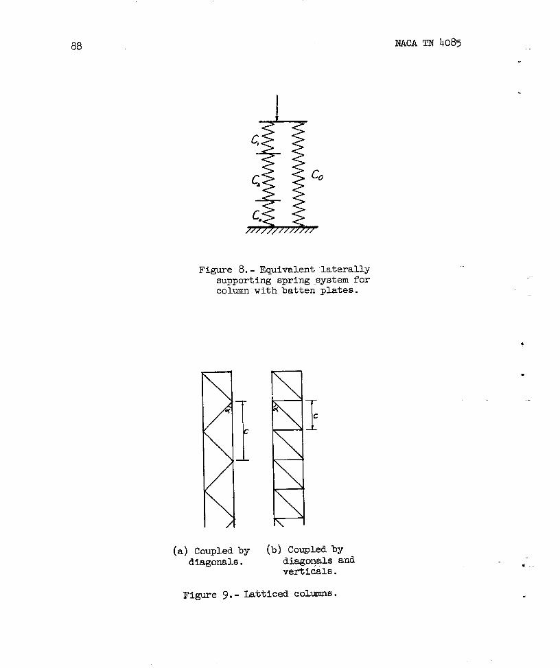
88
I~
c*
c,
////////////7
Figure 8.- Equivalent laterallysupporting spring system forcolumn with batten plates.
(a) Coupled by (b) Coupled bydiagonals. diagoqals and
verticals.
Figure 9.- Latticed colunms.
NACATN 4085
.
.
*
.
w.
.

~DNACA TN 4085
.
.
I I 10s.
I I
89
Plan and cross section.
Figure 10.- Long sandwich plate compressed in X-direction and clampedat unloaded edges.

90 NACA TN 4085
Figure 11.- Long sandwich plate withisotropic faces and an orthotropiccore compressed in X-directionwith arbitrsry boundary conditionsat unloaded edges.
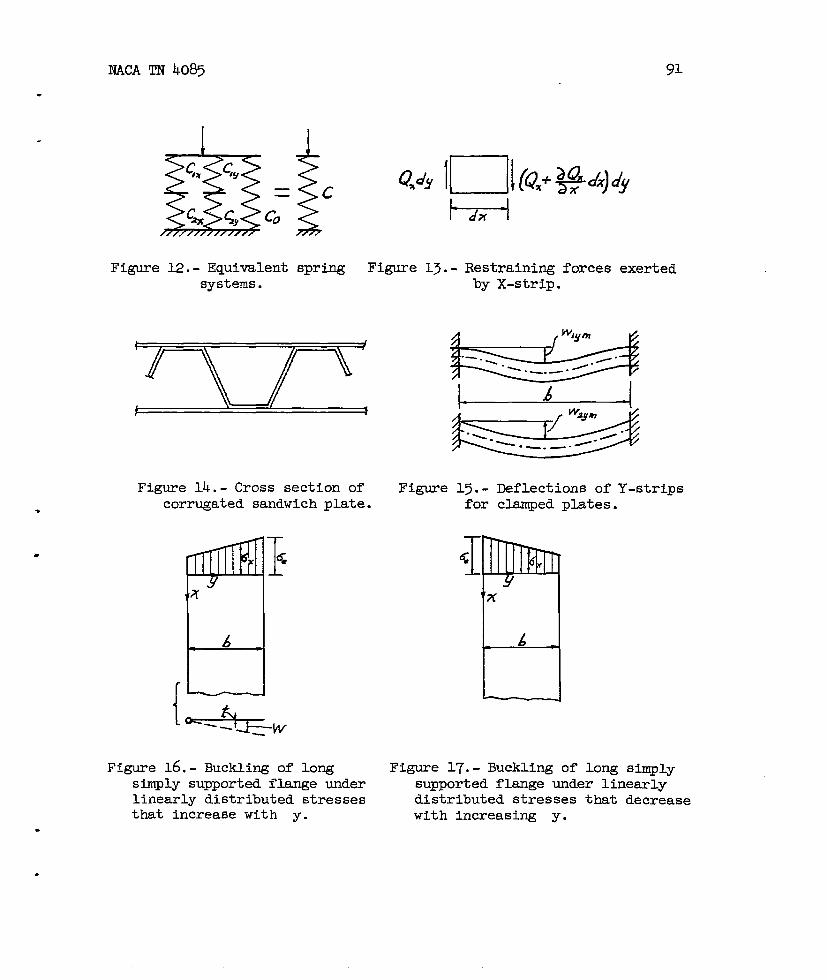
NACA TN 4085 91
——
Figure 12.- Equivalentsystems.
$cspring
@?Y l~lk?x’~d+’’””
!- -1I
Figure 13.-
dx I
Restraining forces exertedby X-strip.
zIzE -wFigure 14.- Cross section of
corrugated sandwich plate.
Figure 16.- Buckling of 10Ilgsimply supported flange underlinearly distributed stressesthat increase with y.
Figure 15.- Deflections of Y-stripsfor clamped plates.
I<1
Figure 17.-
7?( 6
— -1
Buckling of long sirrrplysupported flange under linearlydistributed stresses that decreasewith increasing y.

92
Figure 18.- Distribution of totaldirect stresses ox and ay
in postbuckling range.
NACA TN 4085
.
.
.
—

93
.
.
8
7
6
3
2
Figure 19. - plot Of cultl~cr/
as function of au cry=.

94 NACA TN 4085
(a) Total deflection.
(b) Deflection for case 1.
(c) Deflection for case 2.
Figure 20.- Deflection of cross section of I-section.
*

NACA TN 4085 95
t
wEa
+-’+ ’+’-+-’-+. ~“’ I
●Figure 21. - Stringer panels supported by stiffeners
and located at equal distances.of equal cross section
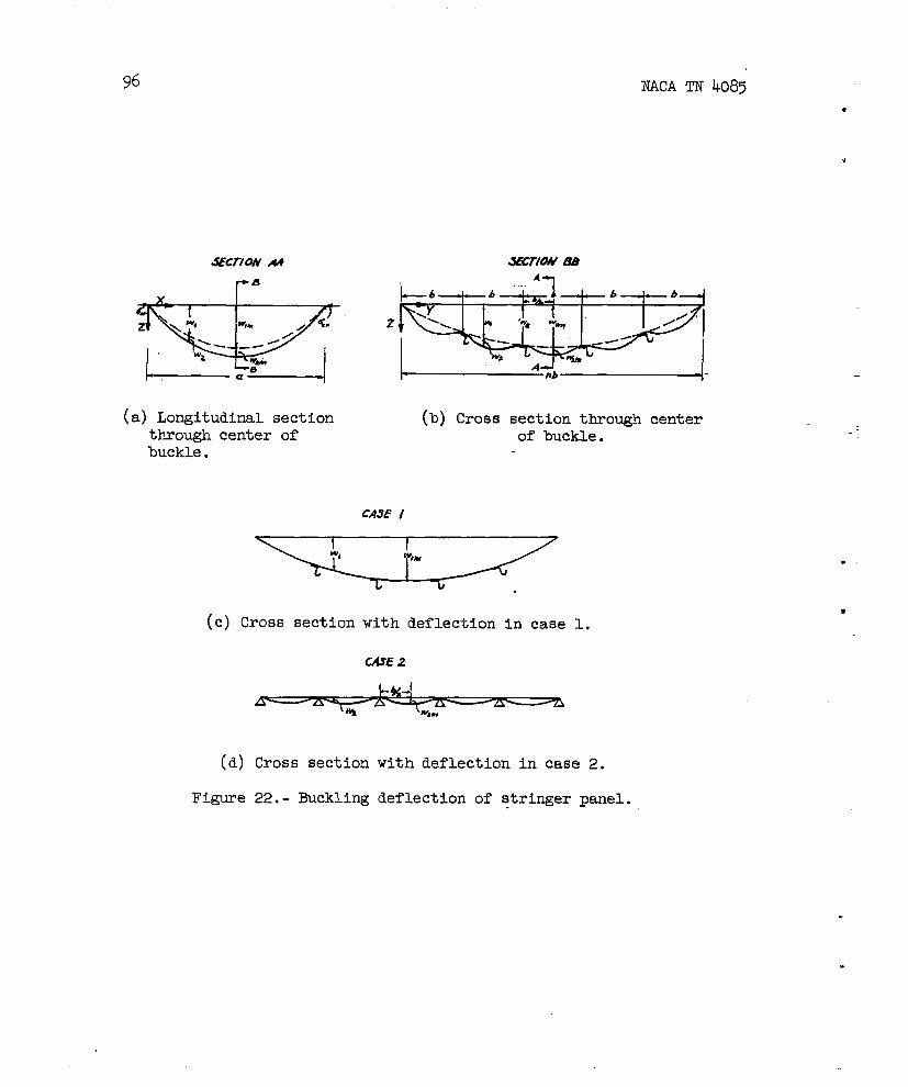
96 NACA TN 4085
●
u
(a) Longitudinal sectionthrough center ofbuckle.
A--l
(b) Cross section through centerof buckle.
CASE 1
(c) Cross section with deflection in case 1.
WE 2
(d)
Figure
Cross section
22.- Buckling
with deflection in case 2.
deflection of stringer panel.
.
.
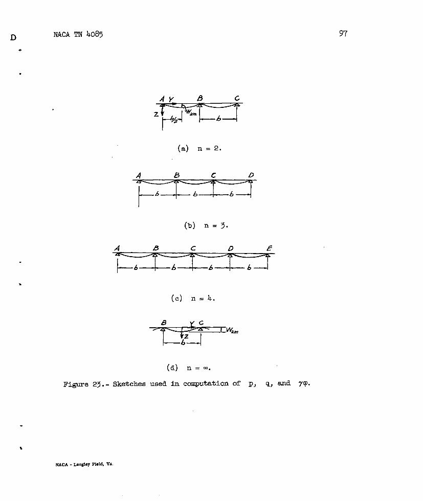
.
.
.
(a) n = 2.
(b) n = 3.
A B c D f?
I
(c) n = 4.
(d) n = M.
Figure 23.- Sketches used in compuwtion of P, q; and 7P.
NACA - Langley NoM, Va.