1.1 Coordinate Plane Geometry. Objectives/Assignment: Plot points on the Coordinate Plane.

TECHNICAL MEMORANDUM
MULTIPLE S C A T T E R I N G CALCULATIONS:
G E O M E T R Y FOR S P H E R I C A L A T M O S P H E R E S
https://ntrs.nasa.gov/search.jsp?R=19710016884 2020-04-22T00:19:52+00:00Z

BELLGOMM. INC. 9 5 5 L'ENFANT PLAZA NORTH, S . W . , WASHINGTON, D . C . 2 0 0 2 4
COVER SHEET FOR TECNNlCAL MEMO
TITLE- Multiple Scattering Calculations : TM-71-1011-5 Geometry for Spherical Atmospheres
DATE- April 16, 1971 F l L l N G CASE NO(S) - 2 3 5
A U T H O R I S ) - E . . N - Shipley FIL ING SUBJECT(S) Planetary Atmosphere ( A S S I G N E D B Y A U T H O R ( S ) ) - ~ ~ l t i ~ l ~ scattering
A B S T R A C T
This memorandum describes the geometric relation- ships that arise in carrying out atmospheric calculations for a spherical planet. These relationships were developed for the specific case of light scattering from a planetary atrnos- phere or haze, as a part of Bellcomm's participation in the Mariner Mars '71 mission. However, the geometrical relation- ships are of general use in a wide range of problems that involve a spherical surface.
In order to obtain the apparent brightness in a scattering atmosphere, one must solve an integro-differential equation (the equation of radiative transfer). This can be accomplished by an iterative process using a digital computer. The brightness in the atmosphere is represented by its value for a set of directions at each one of an array of points in the atmosphere. Cylindrical symmetry about the sun-planet axis reduces significantly the number of points necessary to provide an adequate description of the brightness function.
A point in the atmosphere is described by two variables: its height above the surface of the (spherical) planet, and the angle between the local vertical through the point and the sun-planet axis. The direction of a line of sight from the local point is described by its polar angle to the local vertical and its azimuthal angle measured about the local vertical. Geometric relationships have been developed which give the coordinates of a new
- * local point located a specified distance along the line of
Y sight, as well as the directions of the line of sight at a, - the new point. rl

Part of the atmosphere is shielded from the incident solar radiation by the planet itself. The equation of radia- tive transfer has a discontinuity if the line of sight passes into the shadow region. Geometric relationships that yield the distances, if any, at which the line of sight enters or leaves the shadow region have been developed. A computer subroutine, written in the FORTRAN V language, carries out the necessary shadow calculations.
DISTRIBUTION
COMPLETE MEMORANDUM TO -
O F F I C I A L F I L E C O P Y
plus one wh i te copy for eoch add i t iona l cose referenced
T E C H N I C A L L I B R A R Y ( 4 )
NASA H e a d q u a r t e r s
W. 0. A r m s t r o n g / M T X P . E . C u l b e r t s o n / M T N. W. C u n n i n g h a m / S L E . W. G l a h n / S L E . W. H a l l / M T G H. F . H i p s h e r / S L W. J a k o b o w s k i / S L R. K r a e m e r / S L R. L . Lohman/MF D. R. L o r d / M F A. S . Lyman/MR M. M i t z / S L L . R o b e r t s / M T G ( 2 ) A. D. S c h n y e r / M T E M. G. Waugh/MT-1 J. W. Wild/MTE NASA H e a d q u a r t e r s L i b r a r y
( U S S - 1 0 ) ( 2 )
Ames R e s e a r c h C e n t e r
J. B. P o l l a c k
G o d d a r d Space F l i g h t C e n t e r
I COMPLETE MEMORANDUM TO
I L a n g l e y R e s e a r c h C e n t e r -
M a n n e d Spacecraft C e n t e r
I N . H. H o r o w i t z R. B. L e i g h t o n B. C. M u r r a y G. N e u g e b a u e r R. P . Sharp
C o r n e l l U n i v e r s i t y
C . S a g a n
M a s s a c h u s e t t s I n s t i t u t e of Technology
T . B . M c C o r d I . I. Shapiro
New M e x i c o S ta te U n i v e r s i t y
B. S m i t h
R a n d C o r p o r a t i o n
M. E . D a v i e s
I S t an fo rd U n i v e r s i t y S c h o o l of Medicine
I J. L e d e r b e r g Jet P r o p u l s i o n L a b o r a t o r y E . L e v i n t h a l
U n i v e r s i t y of A r i z o n a
W . K. H a r t m a n n
U n i v e r s i t y of C o l o r a d o
C . A. B a r t h

DISTRIBUTION LIST (CONT ' t. )
U n i v e r s i t y of Texas
G. de Vaucouleurs
U n i v e r s i t y of Washington
C. Leovy
USGS - F l a g s t a f f , Ar izona
R. M. Batson W. T. Borgeson H . Masursky R. L. Wildey
USGS - Menlo Park . C a l i f o r n i a
M. H. C a r r J. F. McCauley
. D . J. Mi l ton D. E . Wilhelms
Bellcomrn, I n c .
G. M. Anderson A. P . Boysen, Jr. D. A. D e Graaf D. R. Hagner N. W. Hinners J . Kranton H. S . London K . E . Mar t e r s t e ck R . K . McFarland J. Z . Menard G. T. Orrok R. V. Spe r ry W. S t r a c k J . W . Timko ( 2 ) J. E . Waldo M. P . Wilson A l l Members, Depts . 1011 & 1013 Department 1024 F i l e
A b s t r a c t Only t o
J. P. Downs D. P . Ling R. L. Wagner
BELLCOMM. I N C . 955 L'ENFANT PLAZA NORTH, S.W. WASHINGTON, 8. C. 20024
SUBJECT: P4ultiple Scattering Calculations : DATE: April 16, 1971 Geometry for Spherical Atmospheres Case 235 FROM: E. N. Skipley
TECHNICAL MEMORANDUM
1. Introduction
A computer program has recently been developed to carry out multiple scattering calculations for a spherical atmosphere illuminated by the sun, (l) The computer progrm and its subsequent modifications, which calculate with high accuracy the intensity of light scattered from Martian hazes and atmosphere, were developed as part of Bellcommk partici- pation in the Mariner Mars '71 mission.
One of the problems that arises in carrying out such calculations is the definition of a convenient coordinate system and the determination of the relationships among the variables, These topics form the subject matter for this memorandum, In addition, the calculations themselves have been described (Section 2) in order to provide a basis for understanding the relevance of the quantities that are studied.
The purpose of this memorandum is twofold. First, it is desired to document the computational procedures that have been developed. Second, the geometric definitions are sufficiently broad that the coordinate systems and the relationships among the variables will find use in other contexts. Thus it was desired to make them readily available, The calculations are somewhat tedious, but they are presented in sufficient detail to make the results accessible for further development. Significant equations have been enclosed in boxes to make them more obvious.
Section 2 of this memorandum contains a description of the multiple scattering problem and the approximation pro- cedure that has been used to solve the problem. Section 3 describes the coordinate system and symmetries that are used, and Section 4 describes the relationships among the variables, Section 5 contains an analysis of the shadow region. A sub- routine for carrying out the shadow calculations is given in Appendix B.

2 . Description of the Multiple Scattering Problem
The apparent brightness due to multiple scattering in an atmosphere obeys the relation
(R,@) w(R,O,$) sin 8dOd$
where w(R,O,$) is the luminous intensity incident on a volume element from a direction whose polar coordinates are €I,$ (see Figure 1). The direction @=0 corresponds to light travelling toward the observer. The quantity R measures distance along the line of sight from the observer to the volume element, TTF is the flux in the incident solar radiation, 0, is the polar angle to the direction of the incident sunlight, and r, is the optical thickness along the path from the volume element to the source of incident radiation. The negative sign on the left- hand side of Equation (1) arises because R increases in a direction opposite to the motion of light toward the observer,
B(R,@) is the fraction of the incident light in a unit solid angle that is scattered into a unit solid angle centered at an angle 8 to the initial direction, per unit length travelled by the light. The function B describes corn.- pletely the scattering properties of the atmosphere or haze, The function a ( & ) represents the extinction coefficient for the atmosphere. Both f3 and a are linearly proportional to the density of the atmosphere, and thus they are functions of height above the surface. Their dependence on R arises from the rela- tionship between R and the height above the surface.
In Equation (I), the first term on the right-hand side accounts for the attenuation of light already travelling along the line of sight toward the observer; the attenuation arises from absorption and scattering in the atmosphere at the point R ,
he second term, f3 (& ,0 s)n~e-Ts (" , represents the contribution of the incident sunlight that is scattered toward the observer,
At the point R the sunlight has an intensity n ~ e - ~ s , its intensity
having been reduced by the factor e-TS due to absorption and scattering in the atmosphere.
The third term on the right-hand side, the integral in Equation (I), gives rise to the multiple scattering effects, At any point in the atmosphere, light that has been previously
scattered and/or reflected from the surface is incident from all directions. At the point R, some of this light is scattered toward the observer. This contribution is represented by the integral, which is just an integration of the product of the scattering coefficient and the incident intensity over the com- plete solid angle surrounding the point.
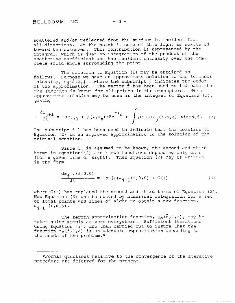
The solution to Equation (1) may be obtained as follows. Suppose we have an approximate solution to the luminous intensity, wj (2, e, 4 ) , where the subscript j indicates the order of the approximation. The vector has been used to indicate that the function is known for all points in the atmosphere. This approximate solution may be used in the integral of Equation (I&, giving
The subscript j+l has been used to indicate that the solution of Equation (2) is an improved approximation to the solution of the original equation.
Since o is assumed to be known, the second and third terms in ~~uationj (2) are known functions depending only on J?, (for a given line of sight). Then Equation (2) may be written in the form
where G (a) has replaced the second and third terms of Equation (2) , Now Equation (3) can be solved by numerical integration for a set of local points and lines of sight to obtain a new function, w j+l (3,e , $ I
-+ The zeroth approximation function, wo(r,Or$)r may be
taken quite simply as zero everywhere. Sufficient iterations, using Equatizn (2), are then carried out to insure that the function wn(r,8,$) is an adequate approximation according to the needs of the problem."
"Formal questions relative to the convergence of the iterative procedure are deferred for the present.
3. Coordinate System
In carrying out the calculations, we must represent the function 0 ( $ , 8 , @ ) by its value at a finite set of points and directions. Such a set of values for w will be referred to as a data base. The number of points that are selected depends -- on the accuracy required of the solution and on the calculation speed and storage capability of the computer that carries out the computations.
The number of points required to define the function o also depends on the symmetry properties of the problem, since symmetry can significantly reduce the number of points necessary to achieve the desired accuracy.
In all of the calculations, the incident sunlight is represented by plane parallel rays. In addition, the following three assumptions are made about the structure of the surface and the atmosphere.
A. The surface of the planet is spherical and homogeneous,
B. The atmosphere has spherical symmetry, that is, the density of the atmosphere is a function only of height above the surface.
C. The scattering law for the surface of the planet is symmetric under reflection in the plane containingr the local vertical and the sun.
It is worth noting that these assumptions are not essential to the technique. However, the coordinate systems and the georrletry that are developed in this and subsequent sections depend, in some circumstances, on the symmetries that arise from these assumptions. Such occasions are pointed out in the text,
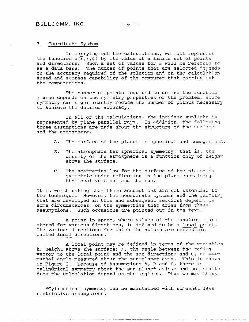
A point in space, where values of the function w are stored for various directions, is defined to be a local point, The various directions for which the values are stored are called local directions.
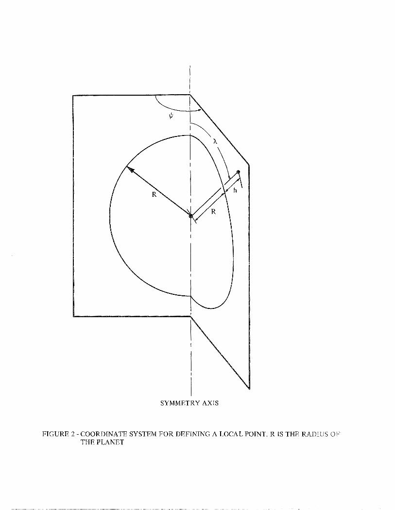
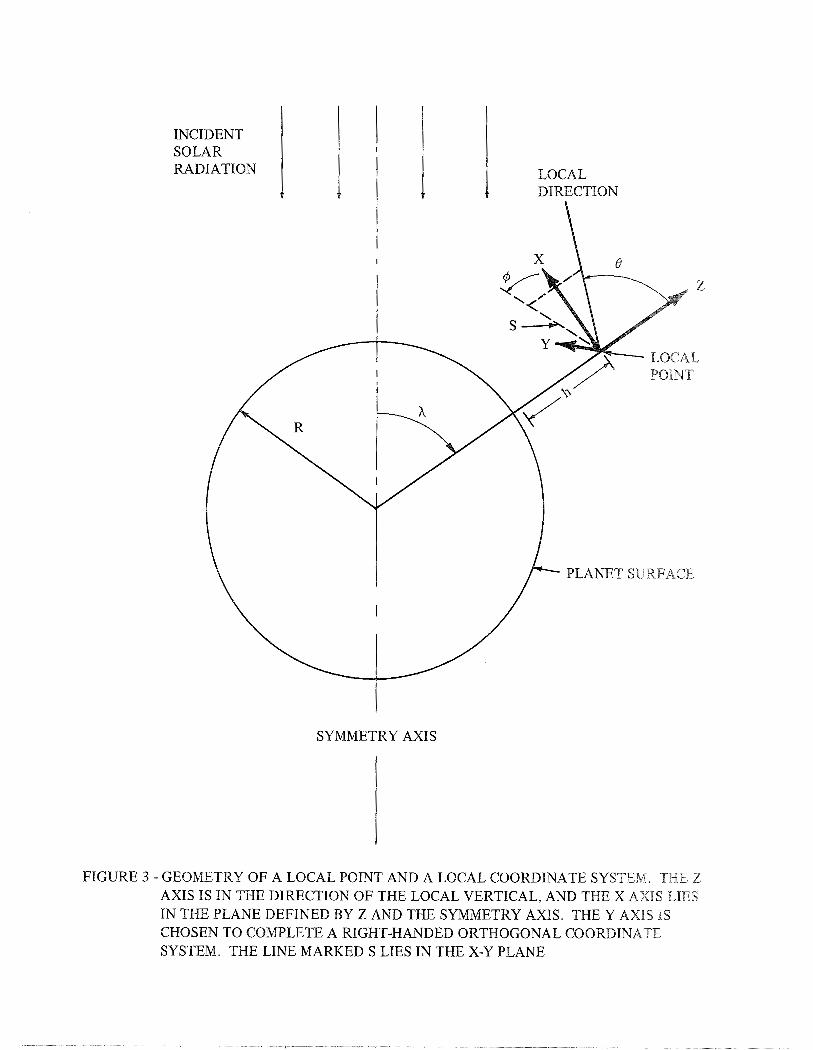
A local point may be defined in terms of the varialbles h, height above the surface; A , the angle between the radius vector to the local point and the sun direction; and $ , an azi- muthal angle measured about the sun-planet axis. This is shown in Figure 2. Because of Assumptions A, B and C, there is cylindrical symmetry about the sun-planet axis,* and no results from the calculation depend on the angle +. Thus we may think
*Cylindrical symmetry can be maintained with somewhat less restrictive assumptions.
of the local points as being confined to a plane; each point is defined by two numbers, h and h (see Figure 3). We will denote the sun-planet axis by the term symmetry axis.
The local directions are defined by the angles 0 and 4 in a local coordinate system as shown in Figure 3. The value of the function w(h,X,B,+) is the intensity of the light incident on the local point h, X from the direction 8, 4 .
There is a further symmetry property. The luminous intensity is invariant to reflection in the plane in which the angle h is measured. This follows from the cylindrical s y m e t r y of the incident light, the atmosphere and the surface and from the fact that light scattering is invariant to such reflections,* Rayleigh scattering is invariant under reflection in any plane containing the incident ray, and Assumption C requires that scattering at the surface of the planet does not violate the symmetry. The reflection invariance is explicitly demonstrated for Equation (1) in Appendix A. In the coordinate system shown in Figure 3, reflection in the X plane corresponds to the transformation
and the symmetry relationship requires
As a consequence, the local directions may be chosen in the hemisphere defined by
Brightness values in the other hemisphere may be obtained by invoking Equation (4) .
*Another way of stating the reflection invariance for light is that for light travelling toward the observer, as much is scattered to the right as to the left, This invariance property holds for all electromagnetic effects, but is violated by certain processes such as beta decay. In order to observe the violation of reflection invariance, it is necessary to use polarized initial states.
B E L L C O M M , INC. - 6 -
In the technique that has been developed to carry out multiple scattering calculations, the local points can be chosen with great generality, so that, for example, the density of local points can be made greater than the average in reg ions where the value of w is changing more rapidly. Similarly, it is possible to choose a different set of local directions for each local point, the directions being chosen to minimize the computational error. However, such stratagems have not been found necessary for achieving adequate computational accuracy, and simpler methods have been used.
The local points have been chosen to be the inter- section of lines of constant height and lines of constant sun angle (A). Further, the same set of local directions is used for each local point. The geometric relations that are developed in subsequent sections do not depend on the choice of local points or directions, but are quite general.
4. Geometric Relationships
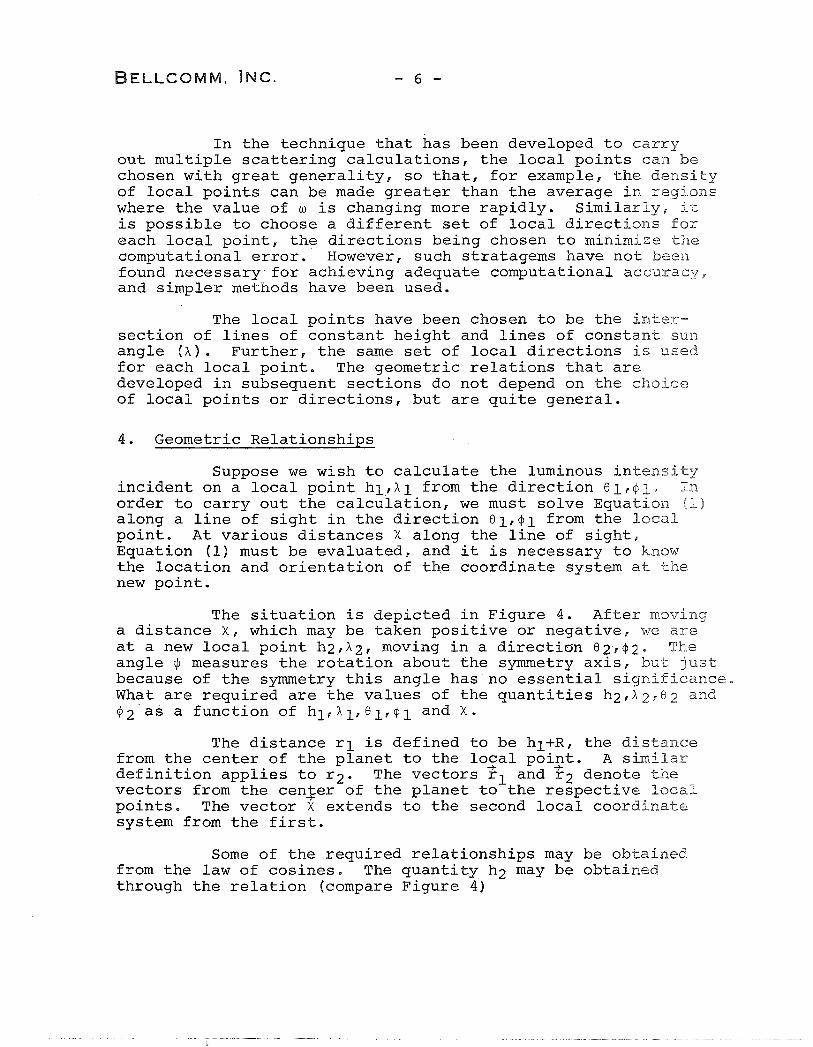
Suppose we wish to calculate the luminous intensity incident on a local point hl,Xl from the direction 81r$1. In order to carry out the calculation, we must solve Equation (1) along a line of sight in the direction 81,@1 from the local point. At various distances X along the line of sight, Equation (1) must be evaluated, and it is necessary to know the location and orientation of the coordinate system at the new point.
The situation is depicted in Figure 4, After moving a distance X, which may be taken positive or negative, we are at a new local point h2,A2, moving in a directian 82r42e The angle I/J measures the rotation about the symmetry axis, but just because of the symmetry this angle has no essential siynificanee, What are required are the values of the quantities h2,X~r02 and +2sas a function of hlrhl,81,+l and X.
The distance rl is defined to be hl+R, the distance from the center of the planet to the lozal poiqt. A similar definition applies to r2. The vectors rl and r2 denote the vectors from the cenler of the planet to the respective local points. The vector X extends to the second local coordinate system from the first.
Some of the required relationships may be obtained from the law of cosines. The quantity h2 may be obtained through the relation (compare Figure 4)
BELLCOMM, INC. - 7 -
whence
Similarly, we have the relationship
and
In order to obtain the remaining quantities, it is convenient to use vector relationships. We need the components,
3 in the E,n,< coordinate system, of the vectors ?l, r2, and 2 . E r n r < is the planet-centered system shown in Figure 4. We have
and similarly
-+ -f
r2 = (h2 + R ) (sinh2cos$) 6 + (sinh sin$): + cosh $ 2 2
3 3 -+ where E r n and are unit vectors along the respective axes,
3
The components of the vector X may be obtained by first obtaining the coordinates in a local coordinate system and then projecting these components onto the cn< coordinate system,
z coordinate system as an intermediary, we Using the xl, ylr find
3
X1 = x (case ls inhl - s ine lcos+lcoshl)
-+ -X ( s ine s i n + l ) II 1
3 +X ( C O S ~ l c o ~ h + s ine cos+ lsinh l ) 5
1
where t h e s u b s c r i p t on 2 i n d i c a t e s t h a t t h e r educ t ion occurred through t h e f i r s t l o c a l coo rd ina t e system. S i m i l a r l y
3
X2 = X ( s inh2cose cos$ - cosh s ine 2cos+2cos$ 2 2
3 + s ine 2 s i n + 2sin$ )
+x (s inh 2cose 2s in$ - cosh s ine 2cos$ 2sin$ 2
3 - s ine 2 s in+ 2cos$ II
Now, w e have t h e v e c t o r r e l a t i o n s h i p
Taking t h e 5 component, w e have
(hl + R) coshl + X (cose cosh + s ine cos+ s inh ) = (h2 + R) cosA 1 1 1 1
Whence w e f i n d

Finally, we have
and by equating the 5 components we obtain
coselcosXl + sine c o ~ ~ ~ s i n X ~ = c0s0~cos X~ + sinQ cos4 sinX 1 2 2 2
giving the result
1 C O S ~ ~ = cos6 cosX +sine cos4 sinh -cos@ cusX (~in@~sinh~) 1 1 1 1 1 2 2
In Equations 8, 14 and 16, angles have been defined by a cosine. In each of the cases, the result is unambiguous, since the angle is restricted to the range between 0 and IT.
In carrying out the multiple scattering calculation, it is also necessary in certain circumstances to calculate the distance from a local point hlrhlr in the direction Oln$i. to another local point having a specified height h2, or a specified sun angle, X2. The distance to a point of height h2 can be obtained from Equation 6.
1/2 2 2 2 x = - (hl+~)cosel (hl+~) cos 8 (hl+~) + (h2+~) 2
Care must be exercised to obtain the desired solution f r o m the two in Equation (17).
It may be seen that in Equation (17), if h2>hlr there is always one positive and one negative solution. The positive answer for the distance is the desired one in our case, For positive x we have
112 x = - 2 2 2 (hl + R) cos8 + h2 + R) - (hl + R) sin e l
for h2 > hl

When h2<hlr there exists the possibility that an answer does not exist. This occurs when the closest approach of the line of sight to the surface is at a height greater than ha. An examination of Equation (17) reveals that, for h2<hl, there are two positive solutions, two negative solutions, or two complex solutions. The complex solutions correspond to the case mentioned above. Our interest is restricted to the smaller positive solution. The requirement that the solutions be positive is that the term -(R + hl)cosel be positive; this necessitates el > r/2. The desired result is
1 / 2 2 2 x = -(hl + ~ ) c o s e ~ - (h2 + R ) ~ - (hl + R) sin
for h2 < hl
Now, suppose A2 is given in addition to the Poeal point hl, A 1 and the local direction 01r41. We can obtain the distance to the second local point by using Equations (7) and (14) simultaneously to eliminate h2. We obtain a quadratic equation with solutions of the form
where
2 a = cos A - (c0s0~cosA + sin0 cosglsinh ) 2
2 1 1 1
- - - (hl + R) 2 2 2 osel (COS A - cos A1) - sin8 c0s4~sinA cosX 2 1 1 621)
2 2 2 c = (hl + R) (cos A 2 - cos "1)
One of the solutions in Equation (20) is extraneous. The correct solution must be determined by seeing which of the distances provides the correct angle A2 in quat ti on 14,

BELLCOMM. INC.
5. Shadow Region
The planet shields a region of space from the sun's rays; this region is called the shadow region. A line of sight may begin in the shadow region, pass through the shadow region, or terminate there by intersecting the surface. For the portion of the path where the line of sight is in the shadow region, the second term on the right-hand side of Equation (1) is zero, Mere important, the boundary of the shadow region represents a dis- continuity in the differential equation because of the change in the term representing the incident sunlight. Consequently, it is essential to the calculations that the distance to the boundaries of the shadow zone be known for a given local direction at a given local point.
The shadow zone is shown in Figure 5. Since the sun is considered to be a source of plane parallel rays, the shadow zone is contained in a cylinder of radius R, situated along the symmetry axis of the problem. The cylinder is divided by the terminator on the planet's surface; the portion of the cylinder away from the sun represents the shadow zone.
Consider a local point h , ~ and a line of sight from that point in the direction 0 , @ . We first ask at what distances, if any, from the local point does the line of sight intersect the surface of the cylinder. Subsequently, we will determine if those points are located in the shadow portion of the cylinder.
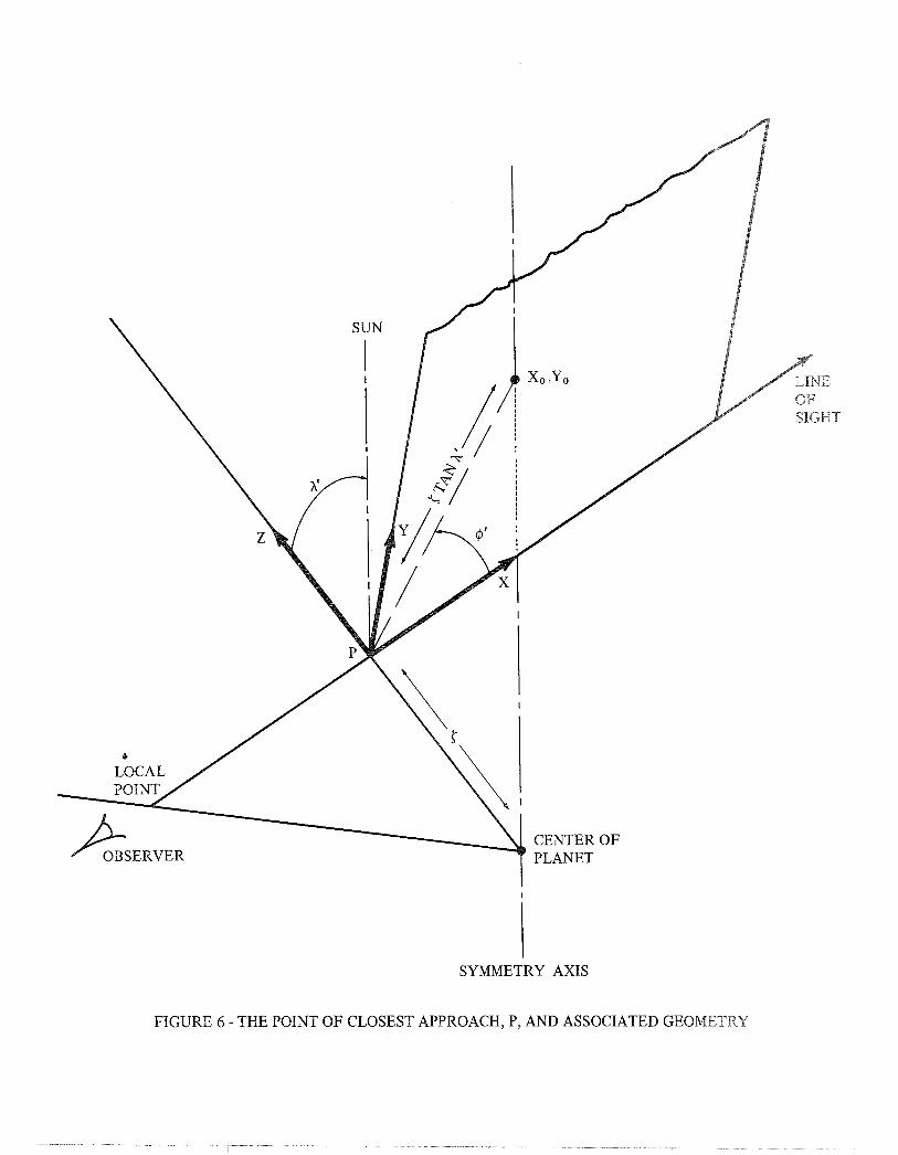
It is convenient to carry out the shadow calculations relative to the point at which the line of sight is closest to the center of the planet. The point of closest approach, which we call P, is a distance Lg from the local point (LC may be positive or negative), and at the point of closest approach the line of sight is a distance 5 from the center of the planet, Straightforward geometric relationships give the results (see Figure 6)
At the point P we establish a coordinate system with the z axis along the local vertical and the x axis along the line of sight (see Figure 6). In this coordinate system,

the angles A' and @ ' , which define the direction of the sun, can be obtained through Equations (14) and (16) respectFveEy,*
The first task is to establish where the axis through the center of the planet toward the sun (the symmetry axis) penetrates the x,y plane. For A' = ~ / 2 , the axis is parallel to the x,y plane; this special situation will be treated separately later in this section.
The point x,,yo, where the symmetry axis penetrates the x,y plane, is a dlstance 5 tan A' from the point P (see Figure 6). Resolving this into components, we find
The Cylinder of radius R cuts the x-y plane in an ellipse centered on the point xQ,yo. To find the equation of the ellipse, we carry out a serles of transformations as illustrated in Figure 7. The xl,yl,zl coordinate system has its origin at xo,yo, the zl axis is parallel to the z axis (at the point P ) , and the xl axis is an extension of the line from P to xo,yo. The yl axis is chosen to complete a right-banded orthogonal coordinate system; the yl axis lies in the x,y p l a n e defined by the coordinate system at the point P. The x2,y2,z2 coordinate system is defined so that its origin is at x,,y,, the 22 axis points parallel to the symmetry axis, and y2 is cornci- dent with yl. The x2 axis is chosen to complete a right-handed orthogonal coordinate system.
The equation for the cylinder about the symmetry axis is
in the x2,y2,z2 coordinate system. In xl,yl,zZ1 coordinate system, Equation (25) is transformed to
*There is a difference between the coordinate system in which A' and @ ' are defined, and the coordinate system used in Section 4. However, a close comparison will reveal that h Y s the same angle as h 2 in Equation (14). $ 2 in Equation ( 1 6 ) is the angle, measured about the local vertical, from the sun direction to the line of sight. In this section, @ ' is the angle, measured about the local vertical, from the line of sight to the sun direction. Hence $ 2 and $ ' differ by a sign, which, however, does not affect the calculation.
2 2 ( X cash' - z s i n h ' ) + yl = R
2 1 1
We a r e i n t e r e s t e d i n t h e e l l i p s e genera ted by t h e i n t e r s e c t i o n of t h e c y l i n d e r and t h e x ,y p l ane , where z l = 0 ; t h e xl and yk axes l i e i n t h e x ,y p lane . The equa t ion of t h e e l l i p s e i s
I n o rde r t o make t h e xl a x i s p a r a l l e l t o t h e x a x i s , t h e xp,yl,zl coord ina t e system must be r o t a t e d by an ang le - + ' about t h e z l a x i s . Remembering t h a t t h e c e n t e r of t h e e l l i p s e i s a t t h e p o i n t xo,y, i n t h e x , y , z coo rd ina t e system, w e have t h e equation of t h e e l l ~ p s e a s
Our i n t e r e s t i s i n t h e p o i n t s A and B where t h e e l l i p s e i n t e r s e c t s t h e l i n e of s i g h t . The l i n e of s i g h t has y=O i n t h e x,y plane (the geometry i s shown i n F igure 8 f o r t h e s p e c i a l c a s e h 1 = v / 2 ) . There- f o r e , t h e p o i n t s of i n t e r s e c t i o n of l i n e of s i g h t w i t h t h e cylinder about t h e symmetrv a x i s a r e t h e s o l u t i o n s t o t h e equa t ion
2 2 2 2 (x-xO) (COS + ' cos h ' + s i n + ' )
2 + 2 (x-xo) yo (cos+ ' s i n + "sin h ' ) 2 2 2
(COS + + s i n + cos A I ) = R 2 + Yo
I n Equation ( 2 9 ) , d i s t a n c e s a r e measured r e l a t i v e t o t h e p o i n t P, The d i s t a n c e LC must be added s o t h a t t h e d i s t a n c e s a r e relative t o t h e l o c a l p o i n t . F i n a l l y , t hen , we f i n d t h e i n t e r s e c t i o n s of t h e l i n e of s i g h t w i th t h e c y l i n d e r t o be
The symbols A and B have been used t o denote bo th t h e points of i n t e r s e c t i o n and t h e d i s t a n c e s from t h e l o c a l p o i n t t o t h e i n t e r s e c t i o n s .
where
2 2 2 a = cos @'cos A' + sin 4 '
b 2 2 2 2 - = yo(cos@'sin@'sin A') - x0(cos @'COS A ' + sin $ 1 ~ 1 2
2 2 2 2 2 c = yo(cos @ ' + sin @'COS A') - 2xoyo(cos@'sin@'sin A')
2 2 2 2 + x (COS $!COS A s + sin 4 ' ) - R 2 0
We note that A and B must both be complex or both be real. If they are complex, it indicates that the line of sight does not intersect the cylinder. If A and B are real and equal, then the line of sight is tangent to the surface of the cylinder, If A and B are real but not equal, then because of the definition in Equation ( 3 0 ) ,
All the following comments refer to the case when A and B are real and distinct.
It must be remembered thatA and B give the points at which the line of sight (taken to mean a line. extending in both positive and negative directions along the local direction from the local point) intersects the cylinder about the s axis. In order to determine if the points refer to the shadow portion of the cylinder (see Figure 5), one may calculate the sun angles h~ and hB at the points A and B , respectively (using Equation 14). The points refer to the shadow zone if their sun angle, AA or AB, is greater than ~ / 2 . However, this requires a relatively long calculation, and a quicker algorithm is available in certain circumstances (see Case I below).
The values of the quantities Lr,<,A and B carry implications about the geometry of the shadow zone relative to the line of sight. This can be organized into three distinct cases.

Case I r; 2 R
The line of sight lies in a plane that is perpendicular to a radius vector at the point of closest approach. For X I = ~ / 2 , a special case to be discussed later, the radius vector is at the terminator (see Figure 5) and the plane does not intersect the cylinder except if 5 5 R. If A ' e 1~12, the plane intersects the cylinder above the terminator, and eon- sequently any intersections between the line of sight and the cylinder occur in the sunlit region. Conversely, if A ' > ~ / 2 , any intersections between the line of sight and the cylinder occur in the shadow zone.
Case I1 r < R , L > 0 5-
The point of closest approach lies inside the planet and hence inside the cylinder. Because of this and Equation (321, there is the relationship
The line of sight penetrates the planet; we may confine our interest to that portion of the line of sight on the near side of the planet, that is, between the local point and the point where the line of sight enters the surface. The point I3 lie; beyond the surface of the planet and is not of interest, The implication of Ly > 0 is that the local direction points toward the planet's surface. If A < 0, then the local point is in t h e shadow zone, as is the entire region between the local point and the surface. If A > 0, then the local point is outside the shadow zone, and the line of sight enters the shadow zone at a distance A from the local point.
Case 111 5 < R, L 5
This case differs from Case I1 in that the line of sight looks away from the planet; and the point B is of concern, If B < 0, then the local point is outside the shadow zone 2nd the line of sight does not enter the shadow zone for positive displacements from the local point. If B > 0, then the IoeaL point is in the shadow, and the line of sight emerges from the shadow zone at a distance B from the local point.

BELLCOMM, I N C . - 16 -
It remains to consider the situation when X q = n n / * The geometry is shown in Figure 8. If 5 > R, then the line of sight does not intersect the cylinder. If 5 = R, the line of sight is either tangent to the cylinder at a point, or, for @ ' = 0 or IT, imbedded in the surface of the cylinder. For bath these cases it is convenient to assign the line of sight to being outside the shadow zone.*
If 5 < R, then the x,y plane intersects the shadow cylinder along two lines, since A ' = ~ / 2 . The perpendicalar distance between the lines is (see Figure 8)
and the line of siqht intersects the lines at distances - + v - 2 sin@' . Thus the points A and B have the values
These equations fail at @ ' = 0 or @ ' = IT. In that circumstance the line of sight is parallel to the symmetry axis and does not intersect the cylinder. For 5 < R, the relevant portion of the line of sight is within the shadow zone if the local point has A > IT/^; for X < ~ / 2 , the relevant portion of the line of sight is in the unshadowed portion of the cylinder. If X = v / 2 , the entire line of sight must lie in the plane of the terminator, since A ' = 1~12. In this case, no portion of the line of sight outside the surface of the planet can be shadowed.
Further development of the equations, including a computer program that caries out the shadow calculations, is given in Appendix B. I-- ' t
.52 ,
Attachments Reference Appendices A and B Figures 1-8
/ E. N. Shipley 2
*Since the cylinder represents a discontinuity, a point on the surface can reasonably be chosen to have either the charac- teristics of the inside or the outside of the cylinder.

BELLCOMM, I N C
1. E. N. Shipley, "Multiple Scattering Calculation for Planetary Atmospheres," Bellcomm TM-70-1014-2, May 15 , 1970.

BELLCOMM, INC.
APPENDIX A
R e f l e c t i o n Symmetry
The purpose of t h i s appendix i s t o g i v e a formal d e r i v a t i o n of t h e r e f l e c t i o n symmetry t h a t has been used i n t h e m u l t i p l e s c a t t e r i n g c a l c u l a t i o n s . While t h e arguments given i n Sec t ion 3.0 a r e adequate , f u r t h e r i n s i g h t (and g r e a t e r conf idence) can be ob ta ined from a more formal d e r i v a t i o n . The appendix i s d iv ided i n t o two p a r t s . Sec t ion A 1 . O con ta ins t h e d e r i v a t i o n of t h e s c a t t e r i n g ang le , which i s r equ i r ed f o r t h e symmetry argument, The symmetry argument i t s e l f i s contained i n Sec t ion A 2 , 0 -
A1.O The S c a t t e r i n g Angle
The s c a t t e r i n g ang le i s t h e ang le between t h e i n c i d e n t l i g h t r a y and t h e s c a t t e r e d l i g h t r a y . I t i s shown i n Figure A-1, I t can be determined e a s i l y by f i r s t 9 o n s t r u c t i n g u n i t v e c t o r s i n t$e d i r e c t i o n of t h e i n c i d e n t l i g h t ( I ) and t h e s c a t t e r e d l i g h t ( S ) . W e have
3 -
s = - s ine cos$ i - s ine s i n ) s j - cases k S S S
A A A
where i, j , k a r e u n i t v e c t o r s a long t h e x ,y , z axes , r e s p e c t i v e l y and 8 $ . and 0 , + a r e t h e p o l a r and azimuthal ang le s for t h e i ' x s s i n c i d e n t and s c a t t e r e d l i g h t r a y s .
Now
s o t h a t
cos 6 = c o ~ e ~ c o s e ~ +
+ ( s ine s s ine 1 . ) (cosm 1 . cos+ + s in4 i s in+ s )

A2.0 Reflection Summarv
It is necessary to express the integro-differsntial equation of transfer (Equation 1) in the coordinate system described in Section 3.
We have
In this equation 6 (8 ir mi; @ S f @ S
) is the scattering coefficient for
for light incident from a direction 0 $ . being scattered in the i' 1
direction Os,+s (see Figure A-1). The minus sign on the left-hand
side arises because distance is measured away from the observer instead of toward him as in Equation (1). The directions A,.@,@ and O f , $ ' are measured in the coordinate system at the local point located a distance X from the observer.
As we noted in Section 3, reflection is accomplished by the transformation ++-$. In carrying out this transformation on Equation (A4), care must be exercised with respect to the integral, The angles 8 \ $ ' are variables of integration. Changing 4 ' to -4)' does not alter the value of the integral, but it does change the sequence in which the directions are summed. In making the trans- formation $ to -$ , it is convenient also to change
w(x,el,$') to w ( x , B 1 , - 4 ' ) and B(0\+',8,$) to B(e\-$'; o r - $ ) ;
then the sequence of integration will remain the same, r e l a t i v e to the direction - 4 , as it was for the untransformed case relative to the direction +$.
The transformed equation is
For Rayleigh scattering, and most other processes, B is a function only of the angle 6, or equivalently cos 6 . First, consider the second term on the right-hand side of Equation A5. It is straightforward, that
since in the two cases the scattering angle is the same. This may be seen from Equation (A3), by substituting the transformed and untransformed directions.
coshcos~ + sinh sine cos$ = coshcos0 + sinhsin0 cos ( - 4 )
It may be noted that this equality depends on the fact that the azimuthal angle for the sun ($i in Equation A3) is zero. This
in turn results since the sun lies in the reflection plane.
Second, consider the integral in Equation (A51 . The scattering angles corresponding to the direction (8 \ $ I ; B,+) and (8 ,-$ ' ; 8 ,-$1 are equal since, from Equation (A3)
cos0 'cose + sine 'sine (cos@ kos$ + sin$sin$) =
cose ' case + sin8 'sin8 cos ( - $ ' ) cos ( -4 ) + sin ( -@ V sin (-0 $
Because of the equality of the scattering angles, we may rewrite Equations (A4) and (A5) in the forms

Comparison of these two equations reveals that w(x,8,+) sa t i s f i e s the same equation as wCx,O,-@). The only remaining question is that of boundary conditions on Equations (A6) and (AT) . If the line of sight does not intersect the surface, the integration of the integro-differential equation may begin a very great distance from the observer, such that the density of the atmosphere is negligible, and the intensity of light travelling along the line of sight toward the observer is zero. This boundary condition is the same for Equations (A6) and (A7).
In cases where the line of sight intersects the surface, Assumption C (Section 3) guarantees that the boundary condition is the same for the transformed and untransformed equations,
Hence we may conclude that the Equation (1) is invariant under reflections in the plane containing the s u n and the local vertical. That is

INCIDENT LIGHT
SCATTERED LIGHT
FIGURE A- I - DEFINITION OF THE SCATTERING ANGLE 6. NOTE THAT THE POLAR AND AZIMUTHAL ANGLES FOR BOTH LIGHT RAYS ARE DEFINED FOR LIGHT MOVING TOWARD THE ORIGIN.

APPENDIX B
Shadow Calculations
A computer program subroutine was written to carry out the shadow calculations described in Section 5. In this appendix, some further development and simplification of the mathematical relations are described;and the computer program itself is presented.
B1.O Detailed Geometry for the Shadow Calculations
Bl.1 Geometry at the Point of Closest Approach
In order to carry out the shadow calculations, it is necessary to have the angles X P and 4 ' at the point of closest approach (compare Section 5 and Figure 6). These may be obtained from Equations (14) and (16), respectively. However, the specific geometry at the point of closest approach permits some sirnplifiea- tion of the equations. Specifically, at the point of closest approach, the line of sight is perpendicular to the l oca l vertical; that is, 8' = n/2.
Let 5 be the distance from the center of the planet: (see Figure 6 ) . Then, since sin (n-8) = sin 8,
where R+h is the height of the local point, and 8 is the polar angle to the line of sight, and
We wish to show that
cosh coshsin8 -sinXcos~cos8
for 8' = n/2
We start with Equation (14) and recognize that
(R+h2) = 5
and x = L 5
and we use Equation (Bl) and (B2) to obtain values of 5 and E c -
We find
COS~' = 1
(R+h) sine (~+hj cosh- (~+h) cose (cosecosh+sin~cos~sin~ )
which immediately simplifies to the desired result (Equation B31.
A simplified equation for + ' can be obtained from Equation (16) by the straightforward substitution.
sin 0 ' = 1
giving
cos 4 ' = (cosh cose + sinh cos+ sine ) /sinh '
It may also be shown, through the straightforward use sf trigonometric relations in Equation ( B 5 ) , that
sin + ' = (sinh sin4 sin^ ' GBQ 1
B1.2 Simplification of the Equations for the Ellipse
2 Consider Equations (30) and (31) . The term (b /4 - sc) can be simplified as follows:
Let
2 2 2 a = a = cos 4 ' cos A' + sin X
2 a = sin h ' sin+ ' cos+' XY
2 2 2 av
= cos A' sin + ' + cos + '
so that

Let Q be the discriminant divided by four
so that
2 ~ = a y:-2aa x y + a x - a a x x y o o X 0
' + 2 a a x y XY x y Yo x x y o o
This yields
B1.3 Shadow Free Conditions
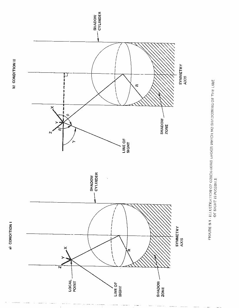
The shadow subroutine is called many times in the course of a single multiple scattering calculation. In order to reduce the computation time as much as possible, it is desirable to recognize as soon as possible in the subroutine geometric conditions for which the line of sight cannot pass through the shadow zone. By this procedure, a great many needless calculations may be avoided. As an ancillary benefit, certain conditions that give rise to inaccurate results, because of rounding errors, are avoided.
Condition I: If the local point is inside the shadow cylinder and has h' 5 112, the line of siqht cannot pass khroush the shadow zone. This is illustrated in Figure ~-l(a),
..
The shadow cylinder is a cylinder of radius R whose axis lies along the symmetry axis, which is the line from the sun through the planet center. The perpendicular distance from the local point to the sun-planet axis is
(R+h) sinh

BELLCOMM. INC. B-4
So the condition that the local point be inside the shadow cylinder is
(R+h) sinh 5 R gB8 1
Condition 11: If the local point is outside the shadow cylinder, and the angle y, defined in Figure B-l(b), is less than or equal to n/2, no shadow is possible. The angle y may be obtained through a simple rotation of the coordinate system, giving
cosy = cos0 sinX -sin0 cos+ cosX (B9,
B2.0 The Com~uter Subroutine
The computer subroutine, SHASCC, is listed in Table B-1, This program has evolved over a period of time, during which the terminology has changed. Consequently, the terminology used in the computer program differs from that used in the derivations given in the text. Table B-2 gives the correspondence between the two sets of variables.
The program.itself follows directly the logic described in Section 5. The following comments, which refer to the speleif'Sc lines in Table B-1, are intended to clarify the procedures employed in the subroutine.
Line 024 This includes a common statement in the subroutine. The common statement is the source of the variable HMX .
Line 030 to 031 The functions CH ( 2 ) and CLP (Y) are used to calculate the angle A ' at points other than the point of closest approach. These correspond to Equation (7) and 6141 , respectively.
Line 053 Rounding errors can create computational difficulties when CSSG is near zero. This statement indicates that there can be no shadow if the point of closest approach is outside of the planet and has a sun angle less than or equal to n/2 (CSSG 2 0). To avoid the rounding errors for CSSG near zero, the calculations are taken as giving no shadow if
CSSG 2- - .003

This corresponds t o A ' I 90.2'.
Line 054 I f CSSG i s near +1 o r -1, s e t CSSG = 1 4 ( A ' = 0 o r 'rr) and 4 ' = 0 . See Lines 119 f f .
Line 084-085 The maximum h e i g h t of t h e atmosphere i s R + HMX. For a l i n e of s i g h t f o r which t h e p o i n t of c l o s e s t approach is a d i s t a n c e 5 from t h e c e n t e r of t h e p l a n e t , one can go a d i s t a n c e XMX, g iven by
i n e i t h e r d i r e c t i o n from t h e p o i n t of c l o s e s t approach and s t i l l remain i n t h e atmosphere. U s e i s made of t h e r e l a t i o n s h i p AA < BB (Equation 3 2 ) . I f BB < -XMX, both AA and BB a r e less t han -XMX, and t h e l i n e of s i g h t w i th in t h e atmosphere i s f r ee of shadow. The same conclusion r e s u l t s i f AA > CXMX. I f AA < -XMX and BB > +XMX, t h e e n t i r e l i n e of s i g h t i s shadowed,
Line 087 t o 090 The d i s t a n c e s AA and BB, h e r e t o f o r e c a l c u l a t e d wi th r e s p e c t t o t h e p o i n t of c l o s e s t approach, a re conver ted s o a s t o be g iven r e l a t i v e t o t h e l o c a l p o i n t .
Line 093 t o 094 Sta tement number 560 is used i f t h e r e
i s no shadow. Sta tement number 550, which sets TL t o .TRUE,, i s used i f some p a r t of t h e shadowed r eg ion of t h e l i n e of sight e x i s t s w i t h i n t h e atmosphere.
Line 109 t o 111 For 5 < R , A ' = 7r /2 and $ " 0 or r r , t h e l i n e of s i g h t i s p a r a l l e l t o t h e symmetry a x i s , and t h e Line of s i g h t does n o t p e n e t r a t e t h e shadow c y l i n d e r . However, t h e e n t i r e l i n e of s i g h t is w i t h i n t h e shadow c y l i n d e r . Two arti-- f i c i a l shadow p o i n t s , chosen t o be w e l l o u t s i d e t h e atmosphere, a r e used t o i n d i c a t e t o t h e c a l l i n g program t h a t t h e l i n e of s i g h t i s shadowed.
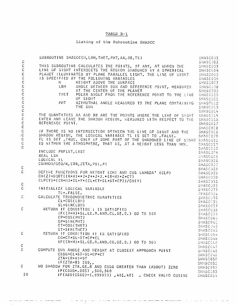
TABLE B-1
L i s t i n g of the S u b r o u t i n e SHASCC
SUBROUTINE SHASCC(I.1, LBM, THET, PHT, AA, BB,TL)
T H I S SUBROUTINE CALCULATES THE POINTS, I F ANY, A T I J l { I CH THE L I N E OF S IGHT INTERSECTS THE REGlON S!iADOWED B Y A SPHERICAL PLAldET l LLUMINATED BY PLANE PARALLEL L IGHT. THE L I N E OF S I G H T I S SPEC1 F I ED G Y THE FOLLOlJl NG VARIABLES
H I I E I G H T ABOVE THE SURFACE LEI4 ANGLE BETP!EEN SUIJ AtJD REFERENCE PO I FIT, E4EASUKED
AT THE CENTER OF THE PLANET THET POLAR ANGLE FROtl THE REFERENCE P O I N T TO THE L I N E
OF SIGI- IT PHT A Z I f4UTHAL ANGLE IblEASURED TO THE PLANE COIJTAI N I N G
THE SUN
TI iE Q U A N T I T I E S AA APJD B B ARE THE PO I PITS Wf-IERE TI4E L l NE OF S l G l l T ENTER AND LEAVE THE SHADOW REGION, i4EASUHED l i l T f i RESPECT TO THE REFERENCE POI NT.
I F THERE I S NO INTERSECTION BETWEEN THE L l N E OF S I G H T AND THE SIiADOl8d REGION, THE LOGICAL VARIABLE T L I S SET TO .FALSE. T L I S SET .TRUE. ONLY I F SOME PART OF THE SHADOWED L l N E OF SBGNT I S k I I T H I N THE ATMOSPHERE, THAT IS, A T A H E I G H T LESS THAN HMX.
l NCLUDE PRFLST, L I S T REAL LBPv1 LOGICAL TL C014MO!.J/GEO/K, ERR, LETA, PS 1, P I
DEFI idE FUIGCTIONS FOR H E I G H T ( C H I AND COS LAMBDA' ( C L P ) C t i ( Z ) = S Q R T ( ( R + H ) * * Z + Z * * 2 + 2 . * ( R + H ) * Z * C T ) CLP(Y)=((R+H)*CL+Y*(CL*CT+SL*ST*CP))/CH(Y)
I N I T I A L I Z E L O G I C A L VARIABLE T L = . FALSE.
CALCULATE T R I GONO~~IETRI C QUANTI T I ES CL=COS ( LBI11 S L=S I N ( LBl4 )
RETURN I F C O N D l T l O N I I S S A T I S F I E D I F ( ( R + H ) * S L . LE.R.ANn.CL.GE. 0.1 GO TO 5 6 0 CP=COS ( PHT) SP=S I N( PHT) CT=COS(THET) S T = S I N ( T H E T )
RETURN I F CONDIT ION I I I S S A T I S F I E D CG=CT*SL-ST*CP*CL IF((R+H)*SL.GE.R.AND.CG.GE.O.) GO TO 5 6 3
COMPUTE SUN ANGLE AND I i E I GHT AT CLOSEST APPROACH P O I N T CSSG=CL*ST-S L*CP*CT Z T A = ( R + H ) * S T I F ( Z T A - R ) 200,,
NO SHADOW FOR ZTA.GE.R AND CSSG GREATER THAN (ABOUT) ZERO I F(CSSG+. 0 0 3 1 ,560 ,560 I F ( A B S ( C S S G 1 - ( . 9 9 9 9 9 ) ) , 4 0 1 , 4 0 1 @ CHECK V A L I D COSINE
S H A S C 0 0 1 S H A S C J 0 2 3 1 i A S C 0 3 3 SHASC ~ 0 4 S H A S C 0 0 5 SHASGOOG S H A S C S 0 7 SI-IASC,'08 S I IASCi209 SWASCJPI) SI - iASCI, ' I l S W A S C 0 1 2 S W A S C 7 1 3 SHASCJQ 4 SWASC3E5 S H A S C 3 1 6 SHASCO17 S t f A S C O l 8 S H A S C O I 9 S H A S C 0 2 0 Sl-IASCii2.S S H A S C 3 2 2 S i f A S C C 2 3 SHASC02cb SPASC1125 Si-iASC3211 S H A S C O 2 7 SE-IASCII2S SE1ASC029 S l i A S C 0 3 0 S M A S C 3 3 1 S H A S C 3 3 2 SWASC533 SiIASC1334 S H A S G I i 7 5 S H A S C r l 3 b S H A S C 3 3 7 SWASC038 SHASCG3'2 SHASCOriO SHASCObE S P A S 6 3 4 2 SEdl\SC3'a3 SIHASC 3 L 4 S H d S C 0 4 5 S H A S C O 4 6 SHASCO 4 7 S H A S C b 4 8 SbiASCu4-3 SHASCO5C S H A S C 3 5 1 Sl iASGOI j .2 3 H A S C 3 5 3 S H A S C d 5 4

CALCULATE TR I GONOt4ETR I C FUNCTl ONS FOR CLOSEST PO l NT CSG2=CSSG**2 SNG?=l . -CSG? SNSG=SQRT(SNG2) TNSG=SNSG/CSSG SNPH=SL*SP/SNSG SNP2=SNPH**2 CSPI i= (CL*CT+SL*CP*ST) / S N S G CSP2=CSPI i * *2
CALULATE THE P O I N T X0,YO ( X P T AND YPT) XPT=ZTA*TNSG*CSPH Y PT=ZTA*TNSG*SNPfl
CALCULATE E L L I P S E C O E F F I C I E N T S CSG2=CSSG**2 AX=CSGZ*CS?2+SNP2 AXY=SNG2*SNPH*CSPH AY=CSG2*S:dP2+CSP2
Q = ( A X Y * * 2 - A X * A Y ) + Y P T * * 2 + A X * R * * 2 I F ( Q ) 560,563, ij RETURN I F Q I S NEGATIVE OR ZERO
CALCULATE I NTERSECTION PO I NTS Q=SQRT ( 4 ) A A = ( - B E T A - Q ) / ( A L P N A ) BB=(-BETA+O,) / (ALPHA)
CHECK THAT SHAD03 POINTS ARE I d l T I i I N THE ATMOSPHERE XMX=SQRT((R+HMX)**2-ZTA**2) 1 F(BB. LT. (-XMX).OR.AA.GT. Xf4X) GO TO 5 6 0
S H I F T TO BOXER COORDINATES XSHFT= ( R + H *CT AA=AA-XSHFT BB=BB-XSHFT I F ( Z T A - R ) 300,,
T L = . TRUE. RETURN

CALCULATIONS FOR ZTA . LT. R I F ( A U S ( C S S G ) - . 0 0 0 0 1 ) ,, 1 0
CONTl NUE FOR LAMBDA' EQUAL P I / 2 OSPH=ABS(CL+CT+SL*ST*CP) IF (ABS(CSPH) .GE. 1 . 0 0 0 0 1 ) W R I T E ( 6 , 7 0 7 ) CSPH
F o R b l A T ( ' 7 0 7 INACCURATE COSINE(PH1) . C s P H = ' F 1 0 . 7 ) IF (ABS(CSPH) .GE. (.99999)) GO TO 2 0 0
USE CSPi i FOR S I N E ( PHI CS PH=SQRT (1. -CS PI4* * 2 ) V=SQRT (R** 2 -ZTA** 2 1 AA=-V/CSPH SB=-AA GO TO 5 0
L A M B D A V W A L P I / ? AND P H I ' EQUAL o O R PI AA=-2. * (R+HMX) BB=-AA GO TO 5 0
LOGIC FOR ZTA .LT. R I F ( X S H F T 1 ,,3?0 CLPA=CLP(AA) I F ( C L P A 1 550 ,560 ,560 CLPB=CLP(BB) I F ( C L P B 1 ,560 ,560 I F ( B B ) 560,560,550
ADJUST TRIGONOMETRIC Q U A N T I T I E S I F S I N ( L A M B D A ' ) = O . SPJPil=O. SI?IP2=0. CSPH= l . CSP2=1. SNSG=0. SNG2=O. TrJSG=O. C S S G = S I G N ( l . ,CSSG) CSG2=1. GO TO 2 0
END
SHASC335 SIIASCG3 6 SHASC03 -7 SHASC093 SHASC399 S H A S C l O ll SHASCPOl SHASCIO2 SI-IASCE0 3 SHASC104 SHASC105 SHASCIOS SHASCl.07 SHASGLOR SHASGlOCE SMASCl.10 S I M A S C ~ I ~ SHASGIL2 SHASGJ.13 SIIASC1lr-b SHASCil5 SHASC11G SHASGP 17 SHASCLP8 SHASG119 SHASC120 SI-EASC12.l SHASC122 SI-BASC.l.23 St(ASC124 SHASClb25 SHRSGJ25 SHASClZB SilASCL28 SI-IASG129 SHASC130
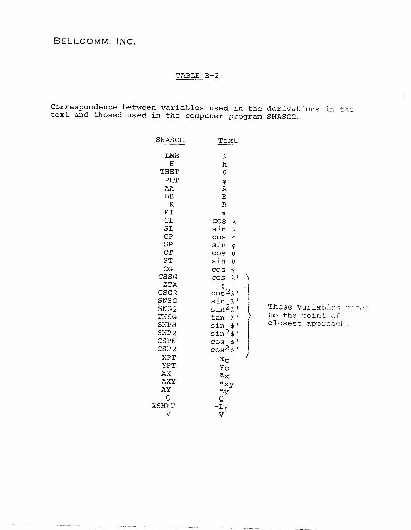
TABLE B-2
Correspondence between variables used in the derivations in the text and thosed used in the computer program SHASCC.
SHASCC
LMB H
THET PHT AA BB
R P I CL S L CP S P CT S T CG
CSSG ZTA
CSG2 SNSG SNG2 TNSG SNPH SNP 2 CSPH C S P 2
XPT YPT AX AXY AY Q
XSHFT v
Text - X h 8
cP A B R 'iT
COs X sin x cos qJ
sin cos 0 sin e cos y cos A ' )
These variables refer
tan A ' to the point of sin + I closest approach, sin2+ ' cos $' COSQ " xo
i Yo ax ax^ a~ Q
-LC v

LINE OF SIGHT
SUN
FIGURE 1 - COORDINATE SYSTEM ALONG THE LINE OF SIGHT. THE X AXIS LIES IN THE PLANE DEFINED BY THE SUN AND THE LINE OF SIGHT
SYMMETRY AXIS
FIGURE 2 - COORDINATE SYSTEM FOR DEFINING A LOCAL POINT. R IS THE RADlUS OF THE PLANET
INCIDENT SOLAR RADIATION
t
LOCAL t DIRECTION
PLANET SURFACE
SYMMETRY AXIS
FIGURE 3 - GEOMETRY OF A LOCAL POINT AND A LOCAL COORDINATE SYSTEM. THE % AXIS IS IN THE DIRECTION OF THE LOCAL VERTICAL, AND THE X AXIS LIES IN THE PLANE DEFINED BY Z AND THE SYMMETRY AXIS. THE Y AXIS IS CHOSEN TO COMPLETE A RIGHT-HANDED ORTHOGONAL COORDINATE SYSTEM. THE LINE MARKED S LIES IN THE X-Y PLANE

LOCAL COORDINATE SYSTEM 1
FIGURE 4 - LOCATION OF ONE LOCAL COORDINATE SYSTEM WITH RESPECT TO ANOTHER THE ORIGIN OF THE tq{ COORDINATE SYSTEM IS AT THE CENTER OF THE PLANET; THE { AXIS POINTS TOWARD THE SUN. BOTH 4, AND 4, ARE S H O W AS NEGATIVE ANGLES. THE LINES MARKED S ARE IN THE RESPECTIVE X-Y PLANES.

PLANET SURFACE
c--
TERMINATOR
SHAD0 ZONE
I SYMMETRY AXIS
FIGURE 5 - THE SHADOW ZONE
CENTER OF PLANET
SYMMETRY AXIS
FIGURE 6 - THE POINT OF CLOSEST APPROACH, P, AND ASSOCIATED GEOMETRY

LINE OF SIGHT
F1GUR.E 7 - COORDINATE TRANSFORMATIONS FOR CALCULATION OF THE EQUATION OF THE ELLIPSE

OBSERVER
SYMMETRY AXIS
FIGURE 8 - SHADOW GEOMETRY FOR A' = n/2.
OF SIGHT
PLANE