Technical Manual Oria Opera Plus ITC -...
26
Global Technical Operations gto.gnresound.com Lautrupbjerg 7-11 • DK-2750 Ballerup • Denmark Phone: + 45 45 75 23 16 • E-mail: [email protected] Technical Manual Oria Opera Plus ITC Beltone Oria O35/ Oria Opera Plus ITC Beltone Oria O35 HPG / Oria Opera Plus HPG ITC
Transcript of Technical Manual Oria Opera Plus ITC -...

Global Technical Operationsgto.gnresound.com
Lautrupbjerg 7-11 • DK-2750 Ballerup • DenmarkPhone: + 45 45 75 23 16 • E-mail: [email protected]
Technical ManualOria Opera Plus ITC
Beltone Oria O35/ Oria Opera Plus ITCBeltone Oria O35 HPG / Oria Opera Plus HPG ITC

Doc. No. 0007580 rev. G
Page 2 of 26
Table of contents
Subject Page
Description ..................................................................................................... 3 Typical performance data ANSI/IEC 118-7 .................................................. 4-9 Part No. lists ............................................................................................ 10-12 Diagram........................................................................................................ 13 Programming cable ...................................................................................... 14 Receiver assembly ....................................................................................... 15 Microphone assembly .................................................................................. 16 Volume Control - Connection ....................................................................... 17 Prepare the faceplate ................................................................................... 18 Hybrid connections.................................................................................. 19-20 Coating ......................................................................................................... 21 Faceplates.................................................................................................... 22 Wiring diagram (CERAMIC) - VC and telecoil (optional).............................. 23 Wiring diagram (FLEX) - VC and telecoil (optional) ..................................... 24 Service tool .................................................................................................. 25 Instrument complete in shell ........................................................................ 26

Doc. No. 0007580 rev. G
Page 3 of 26
Description
Faceplate assembled is delivered in Beige color only. Brown and Tan faceplates are to build locally.
Key features: Clearsound via fully integrated digital class-D Amplifi er. Final assemblies are available in colours Beige, Brown
and Tan. Wax guard.
Programmable via fl ex cable and HI Pro box. Fitting is done through SOLUS 1.2 or higher
(NOAH compatible).
Options: Induction coil (selectable via push-button). Up to 4 acoustical programmes (selectable via
push-button). Digital Volume Control with audible volume change
indication (can be disabled via fi tting software).
Typical Battery life (size 312) 133 hours.

Doc. No. 0007580 rev. G
Page 4 of 26
Typical performance data - IEC 118-7 2cc coupler (Normal power)Data in accordance with IEC 118-7. All sound pressure levels (dB SPL) refer to 20 μPa.Unless otherwise is stated, data are based on a battery voltage of 1.35 V and internal impedance of 5 Ohm.
Tolerance UnitReference test gain at 1600 Hz 33 +/- 5 dB
OSPL90 Max. 115 +3/-5 dB SPL
OSPL90 at 1600 Hz 111 +/- 4 dB SPL
Full-on gain (input 50 dB ) Max. 43 +/- 5 dB
Full-on gain (input 50 dB ) at 1600 Hz 38 +/- 5 dB
Full-on telecoil sensitivity (10 mA/m) 93 +/- 6 dB
Telecoil sensitivity (10 mA/m) at 1600 Hz 88 +/- 6 dB
Typical Harmonic Distortion at 500 Hz 1.8 +3 %
at 800 Hz 1.8 +3 %
at 1600 Hz 1.6 +3 %
Frequency range 200 - 5600 Hz
Typical equivalent input noise 23 Max. 27 dB SPL
Current drain 1.2 20 %
Battery life time Batt. type 312 133 hrs
Full-on gain parameter settingsFrequency : 250 500 1000 2000 4000 6000Max. gain program (FOG) : G50 43 43 43 43 43 35
G80 29 29 29 29 29 29
Doc. No. 0007580 rev. G
Page 5 of 26
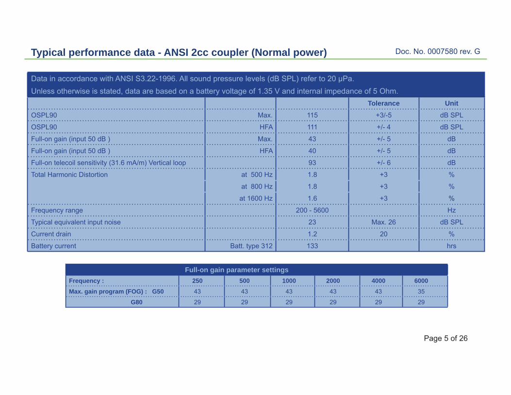
Typical performance data - ANSI 2cc coupler (Normal power)
Full-on gain parameter settingsFrequency : 250 500 1000 2000 4000 6000Max. gain program (FOG) : G50 43 43 43 43 43 35
G80 29 29 29 29 29 29
Data in accordance with ANSI S3.22-1996. All sound pressure levels (dB SPL) refer to 20 μPa.Unless otherwise is stated, data are based on a battery voltage of 1.35 V and internal impedance of 5 Ohm.
Tolerance UnitOSPL90 Max. 115 +3/-5 dB SPL
OSPL90 HFA 111 +/- 4 dB SPL
Full-on gain (input 50 dB ) Max. 43 +/- 5 dB
Full-on gain (input 50 dB ) HFA 40 +/- 5 dB
Full-on telecoil sensitivity (31.6 mA/m) Vertical loop 93 +/- 6 dB
Total Harmonic Distortion at 500 Hz 1.8 +3 %
at 800 Hz 1.8 +3 %
at 1600 Hz 1.6 +3 %
Frequency range 200 - 5600 Hz
Typical equivalent input noise 23 Max. 26 dB SPL
Current drain 1.2 20 %
Battery current Batt. type 312 133 hrs

Doc. No. 0007580 rev. G
Page 6 of 26
Typical performance data 2cc coupler (Normal power)
Max. Output (OSPL90)
120
110
90
80100 1000 10000
Frequency: (Hz)
1302cc Coupler
100
Full on gain and Response gain
100 1000 10000Frequency: (Hz)
10
20
30
40
50
60
Full on Gain 50 dB SPL input
Reference Test Gain 60 dB SPL
2cc Coupler
Doc. No. 0007580 rev. G
Page 7 of 26
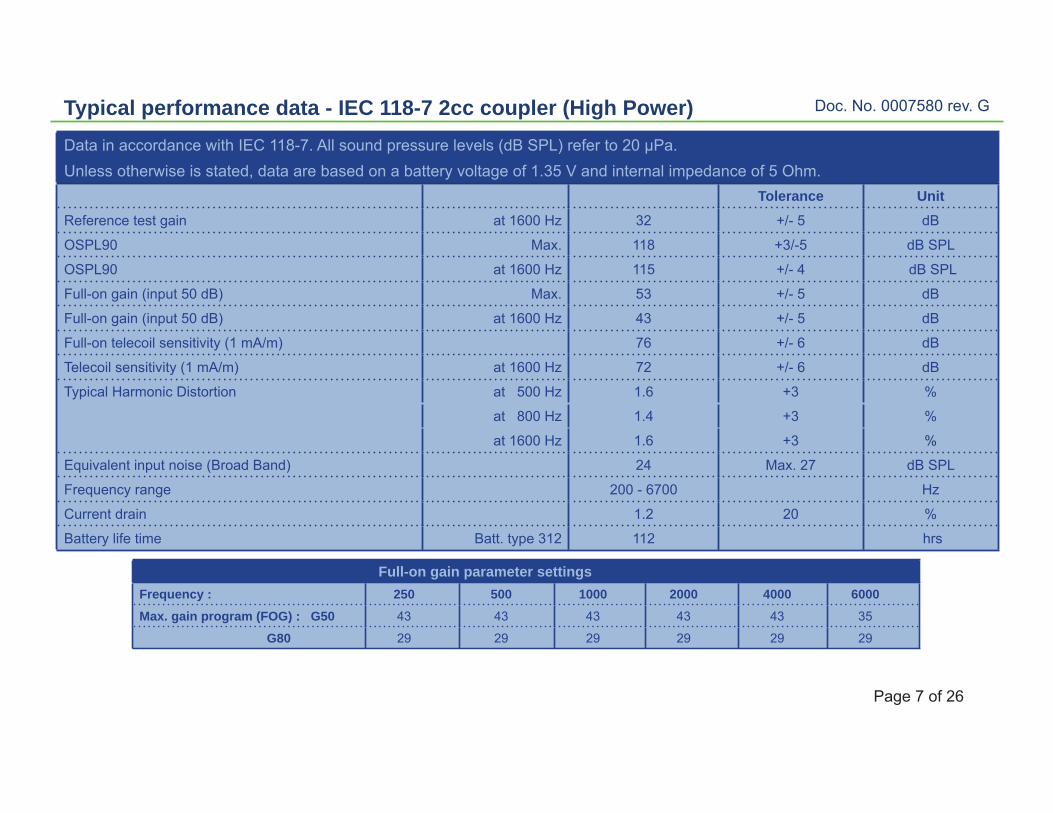
Typical performance data - IEC 118-7 2cc coupler (High Power)Data in accordance with IEC 118-7. All sound pressure levels (dB SPL) refer to 20 μPa.Unless otherwise is stated, data are based on a battery voltage of 1.35 V and internal impedance of 5 Ohm.
Tolerance UnitReference test gain at 1600 Hz 32 +/- 5 dB
OSPL90 Max. 118 +3/-5 dB SPL
OSPL90 at 1600 Hz 115 +/- 4 dB SPL
Full-on gain (input 50 dB) Max. 53 +/- 5 dB
Full-on gain (input 50 dB) at 1600 Hz 43 +/- 5 dB
Full-on telecoil sensitivity (1 mA/m) 76 +/- 6 dB
Telecoil sensitivity (1 mA/m) at 1600 Hz 72 +/- 6 dB
Typical Harmonic Distortion at 500 Hz 1.6 +3 %
at 800 Hz 1.4 +3 %
at 1600 Hz 1.6 +3 %
Equivalent input noise (Broad Band) 24 Max. 27 dB SPL
Frequency range 200 - 6700 Hz
Current drain 1.2 20 %
Battery life time Batt. type 312 112 hrs
Full-on gain parameter settingsFrequency : 250 500 1000 2000 4000 6000Max. gain program (FOG) : G50 43 43 43 43 43 35
G80 29 29 29 29 29 29

Doc. No. 0007580 rev. G
Page 8 of 26
Typical performance data - ANSI 2cc coupler (High Power)
Data in accordance with ANSI S3.22-1996. All sound pressure levels (dB SPL) refer to 20 μPa.Unless otherwise is stated, data are based on a battery voltage of 1.35 V and internal impedance of 5 Ohm.
Tolerance UnitOSPL90 Max. 118 +3/-5 dB SPL
OSPL90 HFA 115 +/- 4 dB SPL
Full-on gain (input 50 dB ) Max. 53 +/- 5 dB
Full-on gain (input 50 dB ) HFA 46 +/- 5 dB
Full-on telecoil sensitivity (1 mA/m) 76 +/- 6 dB
Total Harmonic Distortion at 500 Hz 1.6 +3 %
at 800 Hz 1.4 +3 %
at 1600 Hz 1.6 +3 %
Typical equivalent input noise 24 Max. 26 dB SPL
200 - 6700 Hz
Current drain 1.2 20 %
Battery life time Batt. type 312 112 hrs
Full-on gain parameter settingsFrequency : 250 500 1000 2000 4000 6000Max. gain program (FOG) : G50 43 43 43 43 43 35
G80 29 29 29 29 29 29

Doc. No. 0007580 rev. G
Page 9 of 26
Typical performance data 2cc coupler (High Power)
Frequency: (Hz)10000
Frequency: (Hz)
Max. output (OSPL90)
120
110
90
80100 1000 10000
1302cc Coupler
100
Full on gain and Response gain
100 1000 10
20
30
40
50
60Full on Gain 50 dB SPL input
Reference Test Gain 60 dB SPL
2cc Coupler
Doc. No. 0007580 rev. G
Page 10 of 26
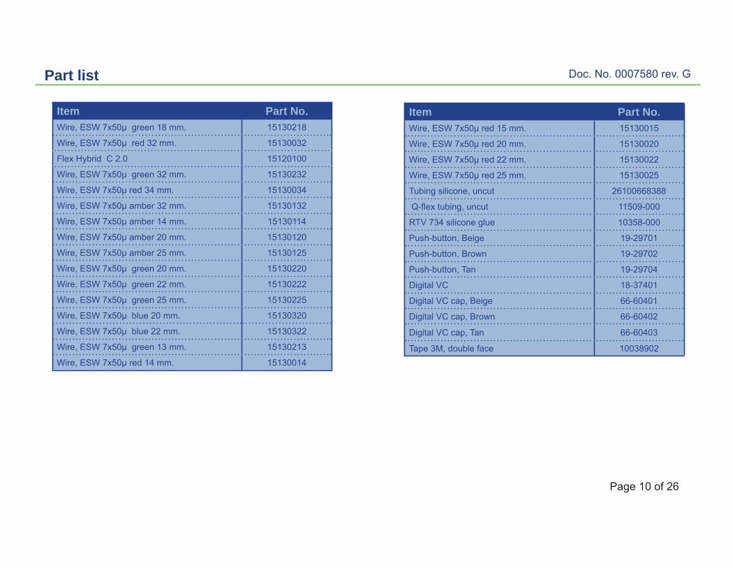
Part list
Item Part No.Wire, ESW 7x50μ green 18 mm. 15130218
Wire, ESW 7x50μ red 32 mm. 15130032
Flex Hybrid C 2.0 15120100
Wire, ESW 7x50μ green 32 mm. 15130232
Wire, ESW 7x50μ red 34 mm. 15130034
Wire, ESW 7x50μ amber 32 mm. 15130132
Wire, ESW 7x50μ amber 14 mm. 15130114
Wire, ESW 7x50μ amber 20 mm. 15130120
Wire, ESW 7x50μ amber 25 mm. 15130125
Wire, ESW 7x50μ green 20 mm. 15130220
Wire, ESW 7x50μ green 22 mm. 15130222
Wire, ESW 7x50μ green 25 mm. 15130225
Wire, ESW 7x50μ blue 20 mm. 15130320
Wire, ESW 7x50μ blue 22 mm. 15130322
Wire, ESW 7x50μ green 13 mm. 15130213
Wire, ESW 7x50μ red 14 mm. 15130014
Item Part No.Wire, ESW 7x50μ red 15 mm. 15130015
Wire, ESW 7x50μ red 20 mm. 15130020
Wire, ESW 7x50μ red 22 mm. 15130022
Wire, ESW 7x50μ red 25 mm. 15130025
Tubing silicone, uncut 26100668388
Q-fl ex tubing, uncut 11509-000
RTV 734 silicone glue 10358-000
Push-button, Beige 19-29701
Push-button, Brown 19-29702
Push-button, Tan 19-29704
Digital VC 18-37401
Digital VC cap, Beige 66-60401
Digital VC cap, Brown 66-60402
Digital VC cap, Tan 66-60403
Tape 3M, double face 10038902
Doc. No. 0007580 rev. G
Page 11 of 26
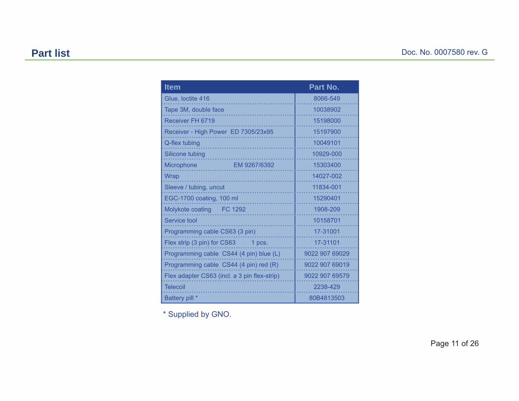
Part list
Item Part No.Glue, loctite 416 8066-549
Tape 3M, double face 10038902
Receiver FH 6719 15198000
Receiver - High Power ED 7305/23x95 15197900
Q-fl ex tubing 10049101
Silicone tubing 10929-000
Microphone EM 9267/6392 15303400
Wrap 14027-002
Sleeve / tubing, uncut 11834-001
EGC-1700 coating, 100 ml 15290401
Molykote coating FC 1292 1908-209
Service tool 10158701
Programming cable CS63 (3 pin) 17-31001
Flex strip (3 pin) for CS63 1 pcs. 17-31101
Programming cable CS44 (4 pin) blue (L) 9022 907 69029
Programming cable CS44 (4 pin) red (R) 9022 907 69019
Flex adapter CS63 (incl. a 3 pin fl ex-strip) 9022 907 69579
Telecoil 2238-429
Battery pill * 80B4813503
* Supplied by GNO.

Doc. No. 0007580 rev. G
Page 12 of 26
Part list
Item Part No.Blank Faceplates-fl oating push-button
Size 312 / Left :
Beige 66-64401
Brown 66-64403
Tan 66-64405
Blank Faceplates-fi xed VC & fl oating push-
button Size 312 / Left :
Beige 66-64421
Brown 66-64423
Tan 66-64425
Battery doors - Size 312 Left :
Beige 66-64551
Brown 66-64553
Tan 66-64555
Faceplates assembled complete - fl oating
push-button, 312 Left :
Beige 15165900
Beige - High Power 15413000
Faceplates assembled complete - fi xed VC
and fl oating push-button, 312 Left :
Beige 15225000
Beige - High Power 15413200
Item Part No.Blank Faceplates-fl oating push-button
Size 312 / Right :
Beige 66-64402
Brown 66-64404
Tan 66-64406
Blank Faceplates-fi xed VC & fl oating push-
button Size 312 / Right :
Beige 66-64422
Brown 66-64424
Tan 66-64426
Battery doors - Size 312 Right :
Beige 66-64552
Brown 66-64554
Tan 66-64556
Faceplates assembled complete - fl oating
push-button, 312 Right :
Beige 15166000
Beige - High Power 15412900
Faceplates assembled complete - fi xed VC
and fl oating push-button, 312 Right :
Beige 15225100
Beige - High Power 15413100

Doc. No. 0007580 rev. G
Page 13 of 26
Diagram
Programming contact pins

Doc. No. 0007580 rev. G
Page 14 of 26
Programming cable
Programming cable CS44: - p/n 9022 907 69029, blue (L.)- p/n 9022 907 69019, red (R.)
Both programming cable sets can be used.
- Programming cable CS63 p/n 17-31001- Flex strip for CS63 p/n 17-31101
Connect the fl ex to the programming cable by using the fl ex end marked with an arrow.
When testing/programming a battery pill must be used. Use e.g. battery pill size 10A (jack plug ø3.5 mm.) p/n 80B4813603.*
- Flex adapter CS63 (incl a fl ex strip) p/n 9022 907 69579

Doc. No. 0007580 rev. G
Page 15 of 26
Receiver assembly
Wire stranded, red, 32 mm p/n 15130032
Wire stranded, green 32 mm p/n 15130232
Place the Qfl ex tubing as shown. Bend the wires. Cut the silicone tubing to 1.3 mm and place it over the wires.
Solder the wires as shown
Silicone tubingp/n 10929-000, uncutCut to 1.3 mm
Qfl ex tubing p/n 10049101, uncut.Cut to approx. 6 mm
BTo Hybrid H13
ATo Hybrid H14

Doc. No. 0007580 rev. G
Page 16 of 26
Microphone assembly
Mic wires:Red wire, 34 mm p/n 15130034Amber wire, 32 mm p/n 15130132Green wire, 32 mm p/n 15130232
Place wrap p/n 14027-002 over the wires as shown.
Silicone tube p/n 11834-001 (uncut).Cut to 3.5 mm.
Place double face tape - p/n 10038902 -as shown and bend the wires towards it .
+ -IN
-IN+
Edge of the mic(marked in red)

Doc. No. 0007580 rev. G
Page 17 of 26
Volume Control - Connection
Volume Control - Connection / Right Volume Control - Connection / Left
Volume Control Cap: Beige 66-60401Brown 66-60402Tan 66-60403 Apply loctite 416 glue to
the base of the Volume Control at the faceplate.
Let air dry for 5 minutes.
Doc. No. 0007580 rev. G
Page 18 of 26
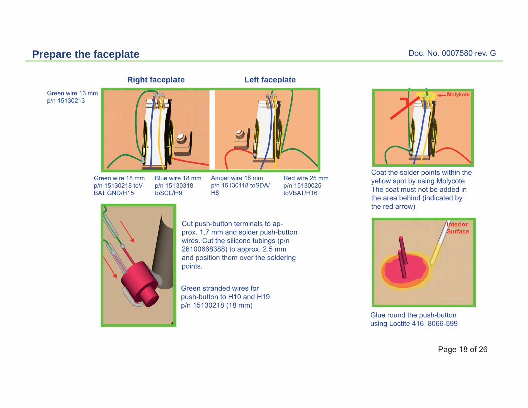
Prepare the faceplate
Green stranded wires for push-button to H10 and H19 p/n 15130218 (18 mm)
Glue round the push-buttonusing Loctite 416 8066-599
Cut push-button terminals to ap-prox. 1.7 mm and solder push-button wires. Cut the silicone tubings (p/n 26100668388) to approx. 2.5 mm and position them over the soldering points.
Left faceplateRight faceplate
Red wire 25 mm p/n 15130025 toVBAT/H16
Amber wire 18 mm p/n 15130118 toSDA/H8
Blue wire 18 mm p/n 15130318 toSCL/H9
Green wire 13 mm p/n 15130213
Green wire 18 mm p/n 15130218 toV-BAT GND/H15
Coat the solder points within the yellow spot by using Molycote. The coat must not be added in the area behind (indicated by the red arrow)

Doc. No. 0007580 rev. G
Page 19 of 26
Hybrid connections (Ceramic)
Pre-tin the soldering points on the hybrid before connecting/soldering the wires.
VREG 2
H17/MIC.+
H1
H9/SCL, 18 mm. 15130318
H14/REC.- (A)
VO
L. U
P
MIC. 2
AUX
MIC. GND 2
H2/MIC. IN H18/MIC.-
H5H6
H7
H3
H4
H10/PS1, push-button
H19/GND, push-button
H8/SDA, 18 mm. 15130118
H13/REC.+ (B)
H16/VBAT, 25 mm. 15130025
VO
L. D
OW
N H15/BAT GND, 18 mm. 15130218
H12H11
Note:All wires must be handled/bent gently in order to avoid any damag-ing to the insulation. When connect-ing/soldering the wires they must be held gently with tweezers to avoid pinching and unraveling.
Coyote 2.0 ceramic
Doc. No. 0007580 rev. G
Page 20 of 26
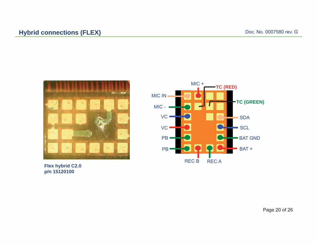
Hybrid connections (FLEX)
Flex hybrid C2.0p/n 15120100
MIC +
MIC IN
MIC -
BAT GND
BAT +
REC A
SCL
PB
REC B
VC
VC
PB
SDA
TC (RED)
TC (GREEN)
Doc. No. 0007580 rev. G
Page 21 of 26
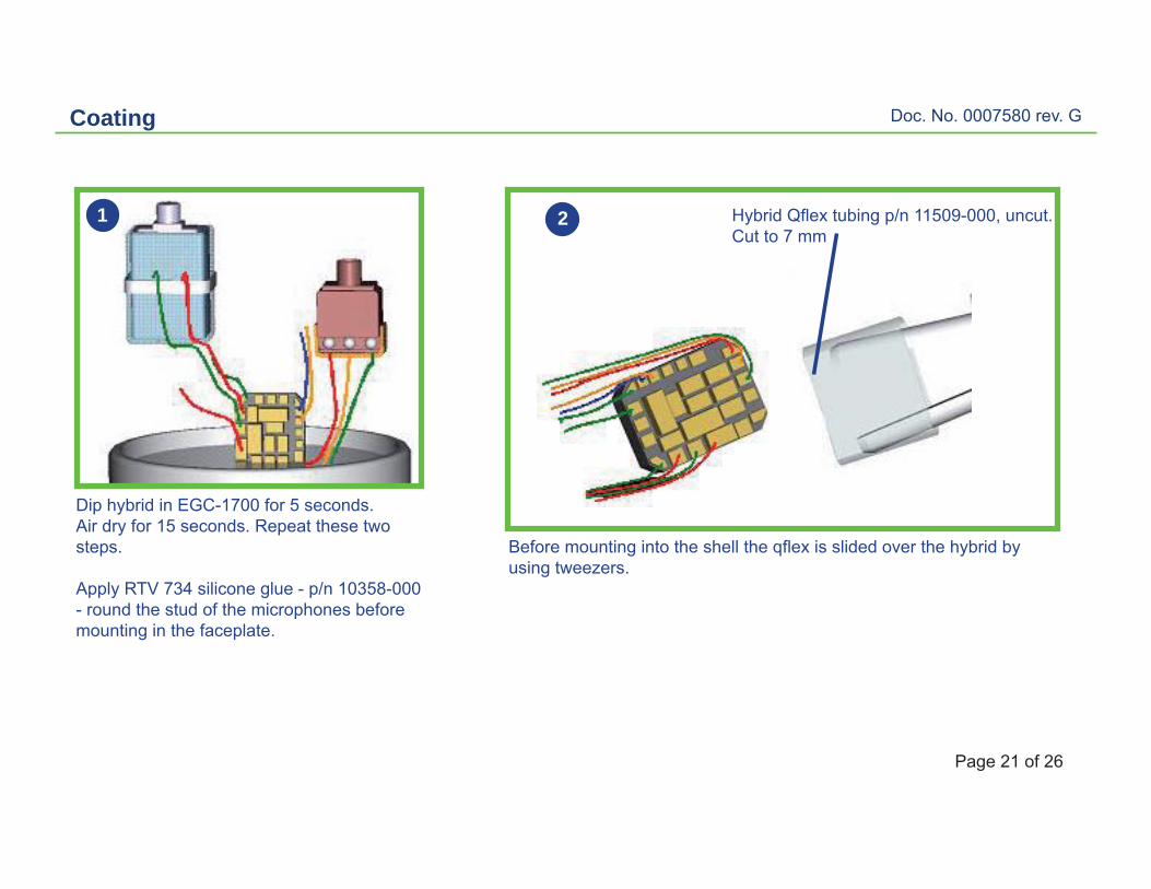
Coating
Hybrid Qfl ex tubing p/n 11509-000, uncut.Cut to 7 mm
2
Before mounting into the shell the qfl ex is slided over the hybrid by using tweezers.
Dip hybrid in EGC-1700 for 5 seconds.Air dry for 15 seconds. Repeat these two steps.
Apply RTV 734 silicone glue - p/n 10358-000 - round the stud of the microphones before mounting in the faceplate.
1

Doc. No. 0007580 rev. G
Page 22 of 26
Faceplates
Leftfl t PB
Left RightLeft Right
Rightfl t PB
Left Right
FP ASM L/R for fxd VC and fl t PBFP ASM L/R for fl t PB
Blank FP L/R for fxd VC and fl t PBBlank FP L/R for fl t PB

Doc. No. 0007580 rev. G
Page 23 of 26
Wiring diagram - (CERAMIC) - VC and telecoil (optional)
H4
Bottom view
Mic, front
(+)
(-)
Left
Push-button
BC
RecH7 H16
H1
H14H15
H11
H19
H10
H12
H13
H8 H9H17
H3
H18
H2
H6
H5
For right side, connect to “C”
For right side, connect to “D”
A
DE
Telecoil option for ITE, ITC models only
Glue the VC with Loctite 416 to fi x it to the faceplate. Add Humiseal round the VC to prevent moisture from seeping the gaps between the VC and faceplate.
Note : Coating EGC-1700 must be added the hybrid after soldering
VC optionVC : ø 4 mm
CERAMIC HYBRID
Doc. No. 0007580 rev. G
Page 24 of 26
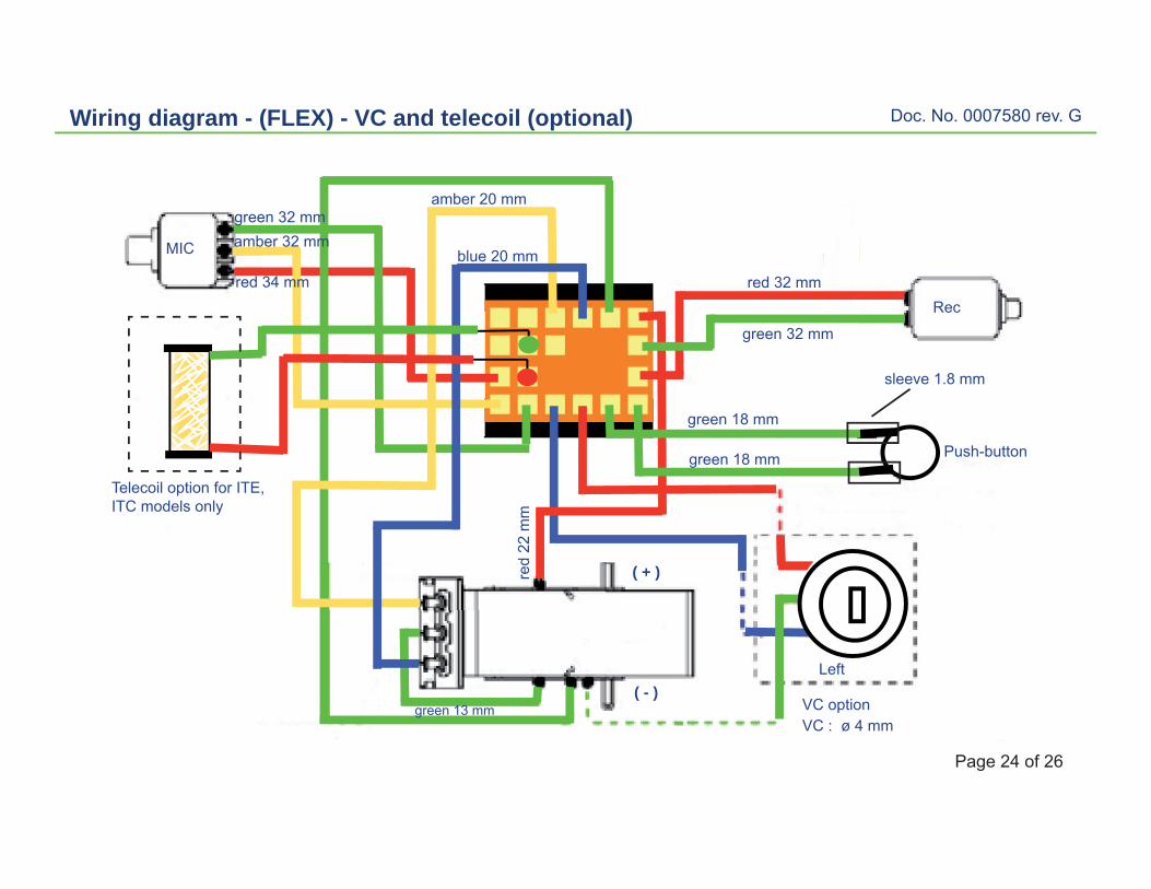
Wiring diagram - (FLEX) - VC and telecoil (optional)
Telecoil option for ITE, ITC models only
Rec
MIC
VC option
Left( - )
( + )
Push-button
VC : ø 4 mm
green 32 mm
green 18 mm
green 18 mm
amber 32 mm
red 34 mm
green 13 mm
red 32 mm
green 32 mm
amber 20 mm
blue 20 mm
red
22 m
m
sleeve 1.8 mm
Doc. No. 0007580 rev. G
Page 25 of 26
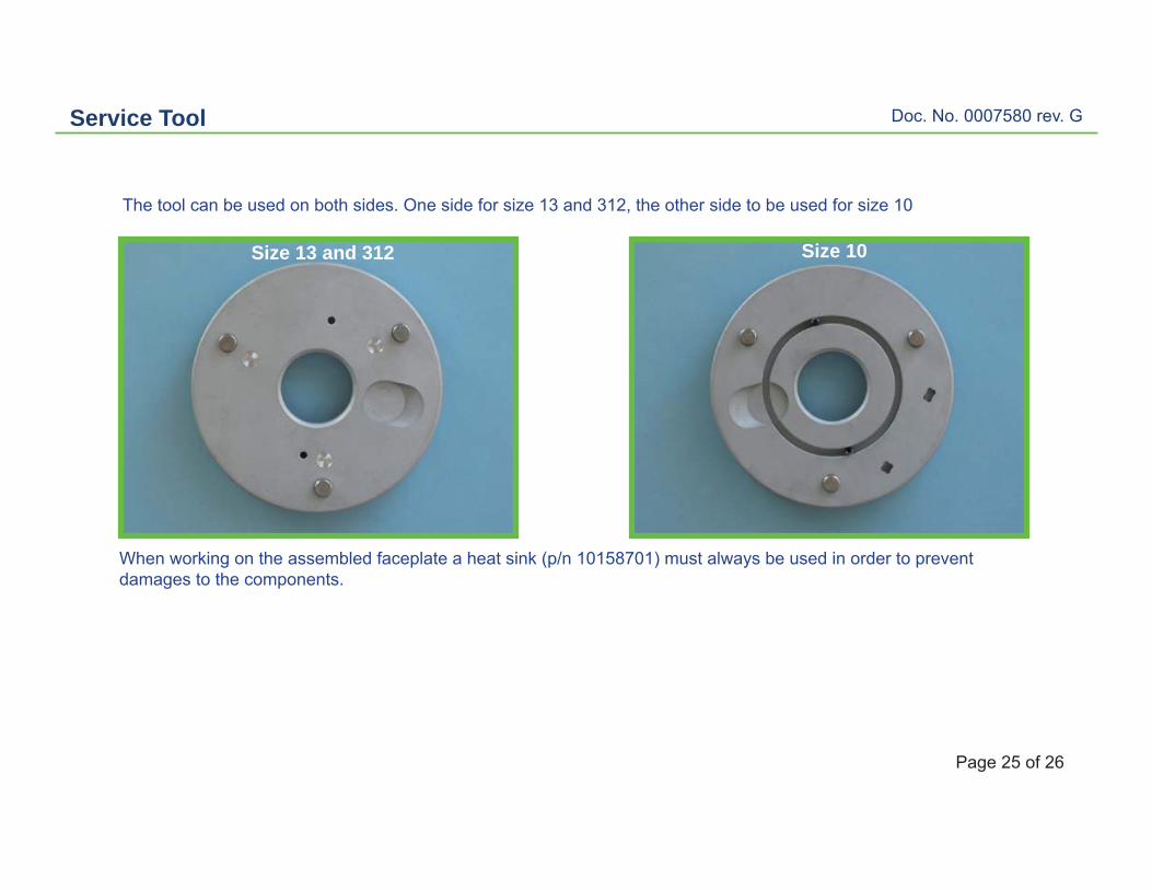
Service Tool
The tool can be used on both sides. One side for size 13 and 312, the other side to be used for size 10
When working on the assembled faceplate a heat sink (p/n 10158701) must always be used in order to prevent damages to the components.
Size 13 and 312 Size 10

Doc. No. 0007580 rev. G
Page 26 of 26
Instrument complete in shell
ITC complete in shell (Image II - Left/Right)Available with or without VC.Push-button to access up to 2 programmes.Telecoil option.
ITC placed in ear