TECHNICAL MANUAL Operator's Manual for WAREHOUSE CRANE … · Technical Manual HEADQUARTERS,...
136
TM 10-3950-672-10 TECHNICAL MANUAL Operator's Manual for WAREHOUSE CRANE 10, 000 LB. CAPACITY, M469 WHEELED, DIESEL POWERED NSN 3950-01-412-5345 (Grove Model AP 308T) Approved for public release: Distribution is unlimited. HEADQUARTERS, DEPARTMENT OF THE ARMY JUNE 1997
Transcript of TECHNICAL MANUAL Operator's Manual for WAREHOUSE CRANE … · Technical Manual HEADQUARTERS,...

TM 10-3950-672-10
TECHNICAL MANUAL
Operator's Manualfor
WAREHOUSE CRANE10, 000 LB. CAPACITY, M469WHEELED, DIESEL POWERED
NSN 3950-01-412-5345(Grove Model AP 308T)
Approved for public release: Distribution is unlimited.
HEADQUARTERS, DEPARTMENT OF THE ARMYJUNE 1997

TM 10-3950-672-10
WARNING
OPERATIONS ADJACENT TO OVERHEAD LINES AREPROHIBITED UNLESS ONE OF THE FOLLOWING
CONDITIONS ARE SATISFIED.
1 POWER HAS BEEN SHUT OFF AND POSITIVEMEANS TAKEN TO PREVENT LINES FROM BEINGENERGIZED.
2 POSITION AND BLOCK VOLTAGE REQD CLEARANCEEQUIPMENT INSURINGNO PARTS, INCLUDING UNDER 50 KV - 10 FEETCABLE, CAN COME 69 KV - 12 FEETWITHIN THE FOLLOWING 115-161 KV - 15 FEET
: CLEARANCES 230-285 KV - 20 FEET345 KV - 25 FEET500 KV - 35 FEET
CHECK WITH YOUR LOCAL POWER SUPPLIER FORCORRECT LINE VOLTAGE
NOTE
READ AND UNDERSTAND ALL OF THE SAFETYWARNINGS AND CAUTIONS CONTAINED INSECTION 2 - SAFETY PRECAUTIONS BEFOREOPERATING THE CRANE, DIRECT ANYQUESTIONS THAT YOU MAY HAVE TO YOURSUPERVISOR FOR CLARIFICATION.

TM 10-3950-672-10
Technical Manual HEADQUARTERS,DEPARTMENT OF THE ARMY
No. 10-3950-672-1 Operator's Manual Washington, DC, 15 June 1997for
WAREHOUSE CRANE10, 000 LB. CAPACITY, M469
WHEELED, DIESEL POWEREDNSN 3950-01-412-5345(Grove Model AP 308T)
REPORTING OF ERRORS
You can improve this manual. If you find any mistakes or if you know of a way to improve the procedures, please let usknow. Mail your letter, DA Form 2028 (Recommended Changes to Publications and Blank Forms) or DA Form 2028-2located in the back of this manual direct to: Commander, US Army Tank-automotive and Armaments Command, ATTN:AMSTA-IMOPIT, Warren MI 48397-5000. A reply will be furnished to you. You may also provide DA Form 2028-2information to TACOM via datafax or e.mail.
TACOM's datafax number for AMSTA-IM-OPIT is: (810) 574-6323 e.mail address is: tacom-tech- [email protected]
Approved for public release: Distribution is unlimited.
TABLE OF CONTENTS Page
HOW TO USE THIS MANUAL .......................... .......................................................................iii
SECTION 1 GENERAL ............................................................................................................................. 1-1
Introduction ...................................... ..................................................................................... 1-1List of Specifications ............................... .............................................................................. 1-1
SECTION 2 SAFETY PRECAUTIONS ............................. ....................................................................... 2-1
General ................................................................................................................................. 2-1Travel Operation.................................. .................................................................................. 2-7Craning Operation.................................................................................................................. 2-8Wire Rope and Sheaves............................ .......................................................................... 2-13Controlled Free-Fall Hoist .................................................................................................... 2-17Electrical Hazards .............................................................................................................. 2-18Personnel Platforms ............................................................................................................ 2-23Cold Weather Operation ...................................................................................................... 2-23Don't Forget ........................................................................................................................ 2-24
SECTION 3 PREPARATION FOR USE .................................................................................................... 3-1
Summary .............................................................................................................................. 3-1Unpacking.............................................................................................................................. 3-1Checking Unpacked Equipment ............................................................................................ 3-1Deprocessing Unpacked Equipment ...................................................................................... 3-1Preliminary Servicing and Adjustment ................................................................................... 3-1
TM 10-3950-672-10
TABLE OF CONTENTS - Continued
SECTION 4 PRINCIPLES OF OPERATION .......................... ................................................................... 4-1
General ................................................................................................................................. 4-1Major Components and Systems ........................................................................................... 4-1
SECTION 5 OPERATING INSTRUCTIONS .......................... ................................................................... 5-1
Controls and Indicators .......................................................................................................... 5-1Preventive Maintenance Checks and Services (PMCS) ......................................................... 5-8Operating Procedures .............................. ........................................................................... 5-23
SECTION 6 MAINTENANCE INSTRUCTIONS ......................................................................................... 6-1
Lubrication Instructions ............................. ........................................................................... 6-1Troubleshooting .................................. ................................................................................ 6-12Installing Cable on the Hoist ................................................................................................ 6-29Cable Reeving ................................... ................................................................................. 6-30Installing Wedge and Socket ............................................................................................... 6-31
APPENDIX A REFERENCES ..................................... ................................................................................A-1
APPENDIX B COMPONENTS OF END ITEM AND BASIC ISSUE ITEMS LIST........................................ B-1
APPENDIX C ADDITIONAL AUTHORIZATION LIST ..................................................................................C-1
APPENDIX D EXPENDABLE/DURABLE SUPPLIES AND MATERIALS LIST ..... ........................................D-1
APPENDIX E LOAD CHART .......................................................................................................................F-1
INDEX ALPHABETICAL INDEX ................................................................................................INDEX-1
ii

TM 10-3950-672-10
HOW TO USE THIS MANUAL
This manual is designed to help you operate and maintain the equipment. All task descriptions will take you step-by-step through the procedure. Don't take shortcuts. Before you begin any task, you should read through the completeprocedure, make sure you know what needs to be done, then go back and follow the steps as written.
Pay particular attention to WARNINGS and CAUTIONS, as they contain information that will prevent injury to personnelor damage to equipment.
Use the alphabetical index at the back of the manual to find a topic not listed in the table of contents.
The definitions of WARNING, CAUTION, and NOTE as used in this manual apply as follows:
WARNING
A WARNING IS USED TO EMPHASIZE THAT IFAN OPERATION, PROCEDURE, OR PRACTICE ISNOT FOLLOWED EXACTLY, DEATH OR INJURYTO PERSONNEL MAY RESULT.
CAUTION
A CAUTION IS USED TO EMPHASIZE THAT IFAN OPERATION, PROCEDURE, OR PRACTICE ISNOT FOLLOWED EXACTLY, EQUIPMENTDAMAGE MAY RESULT.
NOTE
A note is used to emphasize an importantprocedure or condition.
DO NOT OVERLOAD
Weight of load should always be known beforeany attempt is made to lift it.
WARNING
DO NOT OPERATE THIS CRANE WITH A JIB(SWINGAWAY OR EXTENSION) TAKEN FROMANOTHER CRANE OR WITH ONE ORDEREDAND FIELD INSTALLED UNLESS THE PROPERJIB LOAD CHART HAS BEEN INSTALLED IN THECRANE CAB.
iii

TM 10-3950-672-10
WARRANTY
THERE ARE NO WARRANTIES, EXPRESS OR IMPLIED, MADE BY EITHER THE DISTRIBUTOR OR THEMANUFACTURER ON NEW GROVE EQUIPMENT, EXCEPT THE MANUFACTURER'S WARRANTY AGAINSTDEFECTS, MATERIAL AND WORKMANSHIP SET OUT BELOW:
NEW EQUIPMENT WARRANTY
"The Manufacturer warrants each new product made by the Manufacturer to be free from defects in materialand workmanship, its obligation and liability under this warranty being limited to replacing free of charge at itsfactory, any part proving defective under normal use and service within six (6) months from the date of initialsale, lease, or rental, providing the equipment is on record with the Manufacturer as being installed by thedistributor. If the machine is not on record as being installed by the distributor, the Manufacturer will considerthe date of shipment from the factory as the date of initial sale, lease, or rental. This warranty is in lieu of allother warranties, express or implied and the obligation and liability of the Manufacturer under this warrantyshall not include any transportation or other charges or the cost of installation or any liability for direct, indirect,or consequential damages or delay resulting from the defect. Any operation beyond rated capacity or theimproper use or application of the product or the substitution upon it of parts not approved by the Manufacturershall void this warranty. This warranty covers only the products of Grove Manufacturing Company. Theproducts of other Manufacturers are covered only by such warranties as are made by their Manufacturers."
THIS WARRANTY IS EXPRESSLY IN LIEU OF ANY OTHER WARRANTIES, EXPRESS OR IMPLIED, INCLUDINGANY IMPLIED WARRANTY OF MERCHANTABILITY OR FITNESS FOR A PARTICULAR PURPOSE, AND OF ANYOTHER OBLIGATIONS OR LIABILITY ON THE PART OF THE MANUFACTURER, AND GROVE MANUFACTURINGCOMPANY NEITHER ASSUMES NOR AUTHORIZES ANY OTHER PERSON TO ASSUME FOR IT ANY OTHERLIABILITY IN CONNECTION WITH SUCH EQUIPMENT.
NOTE
The Cummins diesel engine is coveredby a separate warranty as described inTM 10-3950-672-24.
iv
TM 10-3950-672-10
SECTION 1
GENERAL
1-1. INTRODUCTION.
This handbook provides information for the operator of the AP308T Grove 10K Warehouse Crane, M469.
The lift capacities are listed on the Load Chart in the cab.
The crane incorporates an all welded steel frame using a single reduction drive axle to provide front wheel drive.Rear axle steering is accomplished utilizing a hydraulic steer cylinder attached to the Grove fabricated rear axle. Theengine is mounted at the rear of the crane and provides motive power through a three speed automatic transmission.The outriggers are oblique telescoping on both the front and rear of the crane.
The superstructure is capable of 360 degrees rotation in either direction. The boom is a 14 to 24 ft (4.2 to 7.3 m)two section full power boom and is trapezoidal in design.
NOTE
Throughout this manual, reference is made to left, right, front, and rear when describinglocations. These reference locations are to be considered as those viewed from the operator's seatwith the superstructure facing forward over the front of the carrier frame.
1-2. LIST OF SPECIFICATIONS.
GENERAL.
Model ..............................................................................................................................................AP308TRated Capacity . ........................................................................................................See Load Chart in cabDrive ........................................................................................................................................2 wheel frontGross Weight ........................................................................... See Lifting and Transportation decal in cab
DIMENSIONS.
NOTE
Dimensions listed are with all components fully retracted.
Overall Crane Length ................... ...........................................................................221.0 in. (561.3 cm)Overall Crane Width ............................... ......................................................................84.0 in. (213.3 cm)Overall Crane Height ............................. .......................................................................92.90 in (235.9 cm)Track Width .................................... .............................................................................72.0 in. (182.8 cm)Tailswing........................................................................................................................42.0 in. (106.6 cm)Tail Sweep.................................................................................................................205.60 in. (522.2 cm)
1-1

TM 10-3950-672-10
DIMENSIONS. (continued)
Turning Radius ................................. ........................................................................183.38 in. (465.7 cm)Wheel Base ..................................................................................................................84.0 in. (213.3 cm)
CAPACITIES.
Fuel Tank(Total Capacity) . ..................................................................................................... 35.0 gal. (132.4 L)(Gauge Level Capacity) .......................................................................................... 30.0 gal. (113.5 L)
Hydraulic Tank(Total Capacity) ....................................................................................................... 35.0 gal. (132.4 L)(Gauge Level Capacity).......................................................................................... 30.0 gal. (1 13.5 L)
Coolant System ................................................................................................................... 24.5 qt (23.1 L)Engine Lubrication System .................................................................................................. 11.5 qt (10.8 L)Hoist
Grove H012........................................................................................................................2.0 qt (1.8 L)Gear Reducer ...........................................................................................................................1 pt (0.47 L)Differential .............................................................................................................................14.0 pt (6.5 L)Transmission (Gearbox)
(Ford) (After partial drain) . .............................................................................5 qt (4.7 L) shallow pan or6 qt (5.6 L) deep pan
(Ford) (After complete drain) ................................................................................... 11.75 qt (11.2 L)
ENGINE.
Make and Model ..............................................................................................................Cummins 4B3.9 LType ...............................................................................4 Cylinder Diesel O.H.V., Naturally-aspiratedBore .................................................................................................................... 4.02 in. (102.1 mm)Stroke ................................................................................................................... 4.72 in. (119.8 mm)Displacement ........................................................................................................ 239 cu in. (3916.4 cm')Horsepower (Net)......................................................................................................................................80Governed RPM .................................................................................................................................... 2400Torque (Net) ........................................................................................... 184 lb ft (25.4 kgm) @ 1500 RPMCombustion System ..............................................................................................................Direct InjectionFuel Injection Pump ...................................................................... Lucas CAV DPA Mechanically-governed
FIRE EXTINGUISHER.
Manufacturer .......................................................................................................................................KiddeType ................................................................................................................................Dry ChemicalRating ........................................................................................................................................... 10 BCWeight ............................................................................................................................2.75 lb (1.25 kg)
TRANSMISSION.
Manufacturer .............................................. ..........................................................................................FordModel ..................................................................................................................................................... C-6Speeds ................................................................................................................3 forward and 1 reverse
1-2

TM 10-3950-672-10TRANSMISSION. (continued)
Gear RatiosLow (1st) ...................................................................................................................................... 2.46:1Int (2nd) ....................................................................................................................................... 1.46:1Direct (3rd) ` ................................................................................................................................. 1.00:1Reverse...................................................................................................................................... 2.175:1Stall Ratio..................................................................................................................................... 1.89:1
Filter ................................................................................................................................................ Internal
REAR (STEER) AXLE.
Manufacturer .....................................................................................................................................GroveType ....................................................................................................................Rigid mounted, wide track
FRONT (DRIVE) AXLE.
Type ................................................................................................................................. Single ReductionRatio.....................................................................................................................................................7.8:1
WHEELS AND TIRES.
Lugs - Front Axle .............................................. .........................................................................................6Rear Axle ...................................................................................................................................................6Torque .......................................................................................................................... 300 lb ft (41.4 kgm)Tire Size ..................................................................................................................................10.00 x 15 HPly ..................................................................................................................................................... 16 PRPressure . ....................................................................Refer to Tire Inflation Table in Appendix E (Sheet 9)
BRAKES.
Service.
Type ....................................................................................Hydraulic w/ Manually-adjustable Brake Shoes
Parking.
Type .............................................................................................. Brake and Shoe Bolted to Transmission
STEERING PUMP.
Manufacturer ...................................................................................................................... Parker-HannifanType .....................................................................................................................................................GearOutput ...............................................................................................................................6 gpm (22.7 Ipm)Displacement ....................................................................................... 0.941 cu in. (15.42 cu cm) per rev.
STEERING CONTROL VALVE.
Manufacturer ............................................................................................................................. Charr-LynnDisplacement ......................................................................................... 14.8 cu in. (242.5 cu cm) per rev.Capacity ...........................................................................................................................6 gpm (22.7 Ipm)
1-3

TM 10-3950-672-10
HYDRAULIC PUMP.
Manufacturer .............................................................................................................Commercial ShearingType ............................................................................................................................................ GearSections ...................................................................................................................................................2GPM .......................................................................................27.4 gpm (103.7 Ipm) @ 2400 RPM and
18.9 gpm (71.5 Ipm) @ 2400 RPM
SWING MOTOR.
Manufacturer ..................................................................................................................................... EatonType .............................................................................................................................................OrbitDisplacement ........................................................................................... 6.2 cu in. (101.5 cu cm) per rev.
SWING GEAR REDUCER.
Manufacturer .....................................................................................................................................GroveType ............................................................................................................................ Gear ReductionReduction Ratio ................................................................................................................................ 27.98:1
BOOM.
Elevation ........................................................................................................................-O to + 70 degreesLength
Two Section .............................................................................................................14-24 ft (4.2-7.3 m)Power ...............................................................................................................................................Full
HOIST.
Manufacturer .....................................................................................................................................GroveDrum Dimension
Diameter ....................................................................................................................9.625 in (24.4 cm)Length .......................................................................................................................... 9.0 in (22.8 cm)
Cable Size ........................................................................................................................ 9/16-inch (14 mm)Maximum Capacity ......................................................................................................................181 ft (55.2 m)Stowage .............................................................................................................................13 5 ft (41.1 m)Permissible Line Pull .................................................................................... Refer to the Line Pull and Reeving
Information Chart in cab
COUNTERWEIGHT.
Type ..................................................................................................................... Welded to turntable
OUTRIGGERS.
Type . ......................................................................................... Oblique telescoping removable beamsLength
Extended..........................................................................................................................5 ft 5 (1.67 m)Retracted ............................................................................................................... 3 ft 5.5 in. (1.08 m)
1-4
TM 10-3950-672-10HYDRAULIC SWIVEL.
Manufacturer .....................................................................................................................................GrovePorts...........................................................................................................................................................6
ELECTRICAL SWIVEL.
Slip Rings ................................................................................................................................................10
ELECTRICAL SYSTEM.
Type ..................................................................................................... Single wire ground return (chassis)System Voltage.................................................................................................... 12 VDC negative - groundBatteries
Number ................................................................................................................................................1Manufacturer .................................. ...............................................................................East Penn Mfg.Model ...................................... ............................................................................................ .......724MFCold Cranking Hours (CCH) ...................................................................................................................Charge Indicator .......................................................................................................Use Voltage Tester
AlternatorManufacturer ........................................................................................................................... PrestoliteRating ................................................................................................................................. 65 amperes
CAB HEATER.
Type .............................................................................................................................................Hot Water
1-5
TM 10-3950-672-10
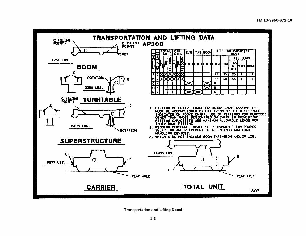
Transportation and Lifting Decal
1-6

TM 10-3950-672-10
SECTION 2
SAFETY PRECAUTIONS
2-1. GENERAL.
It is impossible to compile a list of safety precautions covering all situations. However, there are basic safetyprecautions that MUST be followed during your daily routine. Safety is YOUR PRIME RESPONSIBILITY, since anypiece of equipment is only as safe AS THE PERSON AT THE CONTROLS.
With this thought in mind, this information has been provided to assist you, the operator, in promoting a safe workingatmosphere for yourself and those around you. It is not meant to cover every conceivable circumstance which couldarise. It is intended to present basic safety precautions that should be followed in daily operation.
Because you, the operator, are the only part of the crane that can think and reason, your responsibility is notlessened by the addition of operational aids or warning devices. Indeed, you must guard against acquiring a false senseof security when using them. They are there to assist, NOT direct the operation. Operational aids or warning devicescan be mechanical, electrical, electronic, or a combination thereof. They are subject to failure or misuse.
You, the operator, are the only one who can be relied upon to assure the safety of yourself and those around you. Bea PROFESSIONAL and follow the RULES of safety.
REMEMBER, failure to follow just one safety precaution can cause that accident to people or equipment.
Your are responsible for the safety of yourself and those around you.
Ensure you and those working with you are aware of any special dangers where you are operating the crane. Beespecially careful of dangerous ground and objects; including buildings, near the crane.
Be aware at all times that you are responsible for the safety of yourself, your coworkers, the crane and everythingaround it. Make certain the crane is properly maintained, and then pay attention to winds, boom deflections, rope sway,and any unusual things, which you, as a crane operator, may notice which would not be important to others.
Know and abide by the basic safety rules.
Read and understand the Operator's Manual before entering the cab.
Follow directions on all placards. Know what they mean and follow their instructions.
Be prepared for the work day.
2-1

TM 10-3950-672-10
WARNING
Operators must be thoroughly familiar with safe crane operating practices and have a complete understanding of alloperation and maintenance instructions provided. Operators should be physically fit and thoroughly trained, with relatedexperience, not be easily excitable, not be subject to epileptic seizures, and not be using any drug that could impairphysical, visual, or mental reactions or capabilities.
Wear the proper clothing for the job. Wear personnel protective equipment as required by local or job regulations.
Perform all Preventive Maintenance Services and Checks (PMCS). Refer to Chapter 5. Ensure that routinemaintenance and lubrication are being dutifully performed. Don't' operate a damaged or poorly maintained crane. Yourisk lives when operating faulty machinery, including your own.
Know the area in which you are working. Familiarize yourself with work site obstructions and other potential hazards inthe area.
Use caution when in the vicinity of overhanging banks or edges.
Keep your shoes clean. Before entering the cab, clean any mud or grease from your shoes. This will reduce thepossibility of your foot slipping off a control pedal, possible resulting in an accident.
Since certain shoe sole materials are more slip resistant than others, all operating and service personnel should wearfootwear with high slip resistant sole material.
Avoid a dirty or greasy crane. Keep the cab, deck, and foot and hand holds free of mud and grease for operator safety.Dirty equipment fails rapidly and makes good maintenance difficult.
Observe and heed possible pinch points while performing maintenance or other work.
Check for WARNING tags placed on the crane. If found, refuse to operate the crane until repairs are made andWARNING tags are removed by authorized personnel.
Before performing maintenance, disconnect the battery, remove the ignition key, and place WARNING SIGNS in thecab.
BEFORE performing maintenance on the crane, remove all weight from outrigger jack cylinders, and lower attachmentsto the ground or place them on suitable blocking.
Pressurized air and hydraulic oil can cause serious injury. Be certain all lines, components, and fittings are tight andserviceable. Use a piece of cardboard or wood to search for suspected leaks in hydraulic systems and soapy water tosearch for leaks in pneumatic systems.
Always replace the guards or other safety devices which may have been removed during crane repair or adjustment.
2-2

TM 10-3950-672-10
Have an approved fire extinguisher available and know how to use it. Inspect as required to ensure it is fully chargedand operable.
Remove rings, bracelets, wristwatches, and neck chains before working on any vehicle. Jewelry can catch on equipmentand cause injury, or may short across an electrical circuit and cause severe burns or electrical shock.
Lead-acid battery gases can explode. Do not smoke, have open flames, or make sparks around a battery, especially ifcaps are off. If a battery is gassing, it can explode and cause injury to personnel.
• Ventilate when charging or using in an enclosed space.
• Wear safety goggles and acid-proof gloves when battery cover must be removed or when addingelectrolyte.
• Avoid electrolyte contact with skin, eyes, or clothing. If battery electrolyte spills, take immediate action to stop burning effects:
- External: Immediately flush with cold running water to remove all acid.
- Eyes: Flush with cold water for at least 15 minutes. Seek immediate medical attention.
- Internal: Drink large amounts of water or milk. Follow with milk of magnesia, beaten egg, or vegetable oil. Seek immediate medical attention.
- Clothing or Vehicle: Wash at once with cold water. Neutralize with baking soda or household ammonia solution.
Wear safety glasses or goggles when checking batteries. Always check electrolyte level with engine stopped. Do notsmoke or use exposed flame when checking battery; explosive gases are present and severe injury to personnel canresult.
Disconnect battery negative cable at post prior to performing maintenance in immediate battery area or working onelectrical system. Such disconnections prevent electrical shock to personnel or equipment.
Battery acid (electrolyte) is extremely harmful. Always wear safety goggles and rubber gloves, and do not smoke whenperforming maintenance on batteries. Injury will result if acid contacts skin or eyes. Wear rubber apron to preventclothing being damaged.
Remove all jewelry such as rings, dog tags, bracelets, etc. If jewelry contacts battery terminal, a direct short may resultin instant heating of tools, damage to equipment, and injury or death to personnel.
Check battery condition only with proper test equipment. Batteries shall not be charged except in an open, wellventilated area free of flame, smoking, sparks, and fire.
2-3

TM 10-3950-672-10
Before charging a battery, consult the battery manufacturer's instructions.
Follow standard safety precautions when refueling. FUEL IT SAFELY.
Do not remove the radiator cap when the engine is hot; steam and hot coolant can escape and burn personnel.
Use extreme care when removing the radiator pressure cap. Sudden release of pressure can cause a steam flash whichcould seriously injure personnel. Slowly loosen cap to the first stop to relieve pressure before removing cap completely.After use, securely tighten cap.
Use a clean, thick waste cloth or like material to remove the cap. Avoid using gloves. If hot water soaks through gloves,personnel could be burned.
Do not drain engine oil while engine is hot. Severe injury to personnel may result.
BURN HAZARD
Allow engine to cool before performing maintenance on the muffler, exhaust pipe, exhaust manifold, or turbocharger. Ifnecessary, use insulated pads and gloves.
Do not touch hot exhaust system with bare hands; injury to personnel will result.
EXHAUST GASES CAN KILL
Brain damage or death can result from heavy exposure. Precautions must be followed to ensure crew safety whenpersonnel heater, main, or auxiliary engine of any vehicle is operated for any purpose.
• Do not operate vehicle engine in enclosed areas.
• Do not idle vehicle engine with vehicle windows closed.
• Be alert at all times for exhaust odors.
• Be alert for exhaust poisoning symptoms. They are:
- Headache- Dizziness- Sleepiness- Loss of muscular control
• If you see another person with exhaust poisoning symptoms:
- Remove person from area- Expose to open air
2-4

TM 10-3950-672-10
- Keep person warm
- Do not permit physical exercise
- Administer artificial respiration, if necessary*
- Seek immediate medical attention
* For artificial respiration, refer to FM 21-11.
* BE AWARE, the field protective mask for nuclear-biological-chemical (NBC) protection will not protect you from carbon monoxide poisoning.
THE BEST DEFENSE AGAINST EXHAUST POISONING IS ADEQUATE VENTILATION.
High pressure hydraulics operate this equipment. Refer to TM 10-3950-672-24-1 for hydraulic oil pressure. Neverdisconnect any hydraulic line or fitting without first dropping pressure to zero. A high pressure oil stream can pierce bodyand cause severe injury to personnel.
Diesel or hydraulic fluid under pressure can penetrate skin or damage eyes. Fluid leaks under pressure may not bevisible. Use a piece of cardboard or wood to find leaks, but do not use a bare hand. Wear safety goggles for protection.If fluid enters skin or eye, get immediate medical attention.
Do not move under any hydraulically controlled implement when making adjustment or repairs to hydraulic system.Lower implement and work from above. If implement must be raised for access, always block to support. If implementdrops, injury to personnel can result.
FALLING EQUIPMENT HAZARD
Never crawl under equipment when performing maintenance unless equipment is securely blocked. Equipment may falland cause serious injury or death or personnel.
Keep clear of equipment when equipment is being raised or lowered. Equipment may fall and cause serious injury ordeath to personnel.
Do not work on any item supported only by lift jacks or hoist. Always use blocks or proper stands to support the itemprior to any work. Equipment may fall and cause injury or death to personnel.
Do not allow heavy components to swing while hanging by lifting device. Equipment may strike personnel and causeinjury.
Exercise extreme caution when working near a cable or chain under tension. A snapped cable, shifting or swinging loadmay result in injury or death to personnel.
All personnel must stand clear during lifting operations. A swinging or shifting load may cause injury or death topersonnel.
2-5

TM 10-3950-672-10
Unless authorized and approved by Grove Manufacturing Company, do not make any modifications, alterations, orchanges to a crane which could in any way affect it's original design. Such action invalidates all warranties and capacitycharts, and makes the owner/user liable for any resultant accidents.
Keep your fingers away from potentially hazardous areas.
Use cleaning solutions that are non-flammable and approved for the work being performed.
Always perform a function check after repairs have been made to ensure proper operation.
Load tests should be performed when structural or lifting members are involved.
Do not store flammable materials on the crane at any time.
Never get off or on a moving crane.
When getting on or off a stationary crane, use both hands and use the handrails and steps provided.
Allow No one other than the operator to be on the crane while the crane is functioning or moving.
Check the tire pressure daily. When inflating or adding air to the tires, use a tire cage and clip on inflator. Use anextension hose which will permit standing behind the tire tread when inflating.
When shutting down the crane adhere to the following:
- engage the parking brakes- lower the boom and the load- place the controls in neutral- chock the wheels- ensure the swing lock is engaged.
Don't touch metal surfaces that could freeze you to them.
Dry cleaning solvent (P-D-680) is TOXIC and flammable. Wear protective goggles and gloves; use only in well-ventilated area; avoid contact with skin, eyes, and clothes, and do not breathe vapors. Keep away from heat or flame.Never smoke when using solvent; the flashpoint for type I dry cleaning solvent is 100° F (38°C) and for type II is 138°F(50° C). Failure to do so may result in injury or death to personnel.
If personnel become dizzy while using cleaning solvent, immediately get fresh air and medical help. If solvent contactsskin or clothes, flush with cold water. If solvent contacts eyes, immediately flush eyes with water and get immediatemedical attention.
2-6
TM 10-3950-672-10
CAUTION
Proper lubrication is a requirement in any heavy equipment operation. Follow the factory recommendations regardingthe lubrication time intervals and types of lubricants used. Adjust time intervals accordingly, when working under severeconditions.
When adding oil to the hydraulic system, follow the manufacturer's recommendations. Mixing the wrong fluids coulddestroy seals, causing machine failure.
When performing maintenance, refer to the appropriate manual for instructions. Consult the factory if there are anyquestions regarding procedures or specifications.
Do not attempt repairs you do not understand! Never exceed the manufacturer's recommended relief valve pressuresettings.
Maintain battery electrolyte at the proper level. Check the state of charge indicator with a flashlight.
Keep the crane properly maintained and adjusted at all times. Shut down the crane while making repairs or adjustments.
Keep brakes properly adjusted. Keep brake linings free of oil and grease. Do not over lubricate the bearings or brakeanchor pins. Refer to the Preventive Maintenance Checks and Services (PMCS), Section 5.
Inspect the tires for nicks and cuts, imbedded stones, and abnormal wear. Ensure all lug nuts are properly torqued.
In freezing weather, park the crane in an area where it cannot become frozen to the ground.
The drive line can be damaged when attempting to free a frozen crane.
2-2. TRAVEL OPERATION.
WARNING
Check load limit of bridges. Before traveling across bridges, ensure they will carry a load greater than the crane's weight.
Watch clearances when traveling. Do not take a chance of running into overhead or side obstructions.
Never back up without the aid of a signalman to verify the area behind the crane is clear of obstructions and/orpersonnel.
When traveling, the boom should be completely retracted, lowered, and stowed in its travel position.
Secure the hook block and other items before moving the crane.
2-7

TM 10-3950-672-10
When traveling, keep the lights on, use traffic warning flags and signs, and use front and rear flag vehicles. Check stateand local restrictions and regulations.
Drive carefully and avoid speeding.
Before traveling a crane, check suitability of proposed route with regard to crane height, width, and length.
Secure the turntable before moving crane, use the swing lock.
Stay alert at the wheel.
When parking on a grade, apply the parking brake and chock the wheels.
CAUTION
When moving in tight quarters, post a look-out to help guard against collisions or bumping structures.
2-3. CRANING OPERATION.
WARNING
Check crane stability before lifting loads. Ensure the outriggers (or tires if lifting on rubber) are firmly positioned on solidsurfaces. Ensure the crane is level, brakes are set, and the load is properly rigged and attached to the hook. Lift theload slightly off the ground and recheck the stability before proceeding with the lift. Determine the weight of the loadbefore you attempt the lift. Check the load chart against the weight of the load.
Most accidents involving mobile hydraulic cranes are caused by the following:
- crane out of level- bad surface conditions- outriggers used improperly or not used at all- inadequate blocking under outrigger floats- improper crane operation.
After the crane has been properly set-up, make a dry run before making the first lift. Become familiar with all factorspeculiar to the job site. Know what moves to make BEFORE attaching the first load. Plan ahead.
Unless lifting within On Rubber capacities, the outriggers must be fully extended to provide maximum leveling of thecrane. Remove all weight from tires before lifting on outriggers.
Use adequate cribbing under outrigger floats to distribute weight over a greater area. Check frequently for settling.
Use the sight level bubble indicator to ensure crane leveling.
Use the load line to determine the levelness of the crane. It should always lie in the center of the boom. Check at twopoints 90 degrees apart.
2-8

TM 10-3950-672-10 Be sure the hoist line is vertical before starting the lift. Don't subject the crane to side loadings.
Measure the load radius before making lifts and stay within approved lifting areas. Check your load chart!
The importance of properly leveling a crane cannot be overstressed. A crane only slightly out of-level can quicklyencounter a tipping condition.
Barricade the area around which the crane is working.
Don't interfere with the proper functioning of operational aids or warning devices. Monitor them regularly and see theyget the proper care.
Always refer to the capacity on the load chart in the cab BEFORE making any lift. Position the hoist line to the radiusrequired then lift the load. Stay within the approved work area for the load being lifted.
Remember all rigging equipment must be considered as part of the load. Lifting capacities vary with working area.Permissible working areas are posted in the crane cab. When swinging from one working area to another, ensure loadchart capacities are not exceeded. Know your crane!
Operate the engine at or near governed RPM during performance of all crane operations.
Do not exceed crane rating. Do not rely on the crane tipping stability to determine the maximum lifting capacity. Do notexceed the capacities shown on the load chart in the cab. REMEMBER: ALL LIFTING DEVICES (HEADACHE BALL,BLOCK, JIB, ETC.) ARE PART OF THE LOAD.
Always check the capacity of the crane as shown on the load chart before making any lifts.
Know the weight of all loads before you attempt a lift. Ensure the load to be lifted is within the rated lifting capacity of thecrane.
Always keep the load as near to the crane and as close to the ground as possible.
NEVER exceed the rated lift capacity shown on the load chart. Always check the load chart to ensure the load to belifted at the desired radius is within the rated capacity of the crane.
NEVER use the crane stability to determine capacity. It may be too late when you find out.
Multiple crane lifts are not recommended. The use of more than one crane to make a lift requires the ultimate inequipment, engineering, operating skill, and lift coordination.
BUT, if it is necessary to perform a multi-crane lift, the operator shall be responsible for assuring that the followingminimum safety precautions are taken.
1. Secure the services of a qualified engineer to direct operation.
2. Use one signal person and be sure he is qualified.
2-9

TM 10-3950-672-10
3. Coordinate lifting plans with the operator, engineer, and signal person prior to beginning the lift.
4. Use cranes and rigging of equal capabilities and use the same boom length. Be , , certain cranes are of adequate lifting capacity.
5. Use outriggers on cranes so equipped.
6. Calculate the amount of weight to be lifted by each crane and attach slings at the correct points for proper weightdistribution.
7. Lift only from a stationary position DO NOT TRAVEL.
8. If possible, provide approved radio equipment for voice communication between all parties engaged in the lift.
9. Ensure the load lines are directly over the attach points to avoid side loading the cranes.
Always use enough parts-of-line to accommodate heavy lifts. Provide a safety allowance and reeve more parts of line,rather than fewer parts, than you need. Refer to the values on the load capacity chart for the line weight ratios.
Watch the tail-swing of the revolving superstructure, especially if there are people or obstacles in the area.
Always make daily inspections of the wire rope and replace worn, rusty, or frayed ropes.
Always place the load on the ground when lubricating or adjusting.
A qualified signalman should be available at all times and especially when;
- working in vicinity of power lines- the crane operator cannot clearly see the load at all times- moving the crane in an area or direction in which the operator cannot clearly see
the path of travel.
At all times use standardized hand signals previously agreed on and completely understood by the operator.
If communication with the signalman is lost, crane movement must be stopped until contact is regained.
Watch the load at all times. Watch the signalman and/or load while it is moving. In case you must look in anotherdirection, stop the operation immediately.
Use only one qualified signalman whenever vision is obscured and follow only his directions.
BUT...obey a signal to stop from anyone.
KEEP THE BOOM SHORT. Swinging loads with a long line can create an unstable condition and possible structuralfailure of the boom.
2-10
TM 10-3950-672-10 Sound a warning before moving the crane or when approaching personnel.
Always move toward the load and move slowly. Use a tagline to control the load.
Stay clear of the sheave wheels, holes, and lattice work in telescoping booms and other potentially dangerous areaswhenever the crane is in operation.
Pinch points are impossible to eliminate. Keep all portions of your body away from cable drums, sheaves, pulleys, liftcylinders, and other moving parts of the crane. Be extremely careful when performing maintenance on the crane.
Use extreme caution when lifting with more than one hoist.
Do not strike any obstruction with the boom. If the boom should accidently contact an object; stop immediately. Inspectthe boom. Remove the crane from service if the boom is damaged.
Never push or pull with a crane boom.
Do not add to the counterweight to increase capacity.
When lifting loads, lift slowly and proceed with caution.
Maintaining a steady tension may free the load without shock loading the crane.
Cranes are designed and rated to handle freely suspended loads. Do not pull post, piling, or submerged articles that mayhave a heavy accumulation of mud, silt, or sand.
When lifting loads, the crane will lean toward the boom and the load will swing out, increasing load radius. Ensure theload capacity chart is not exceeded when this happens.
Check the swing brake. Make certain the swing brake operates correctly. Unexpected free swinging of a boom can bedangerous.
Wind and other factors such as boom length, boom angle, size and weight of load being lifted, etc. can affect cranestability and crane structures. Practical working loads for each particular job and lift shall be established by the userdepending upon conditions that exist at the time a lift is being made. Appropriate capacity reductions shall be madewhenever conditions indicate the possibility that a loss of crane stability or structural damage could occur. Be extremelycautious if wind velocity approaches 20 miles per hour.
Exercise caution when swinging loads.
Never swing or lower the boom into the carrier cab.
Stop the hook block from swinging when unhooking a load.
Swinging rapidly can cause the load to swing out and increase the load radius. Swing the load slowly. Swing withcaution and keep the load lines vertical.
Operate the crane only from the crane operator's seat. Operating from any other position, such as reaching in a window,constitutes a safety hazard.
2-11

TM 10-3950-672-10
Never operate the crane with less than two wraps of rope on the hoist drum.
Check the hoist brake by raising the load a few inches and holding it there. Be sure the hoist brake is working correctlybefore continuing the lift. When using a controlled free-fall hoist, slowly return the hoist to normal lowering speed beforestopping the descent of a load. Quick stops could cause the machine to fail. Also refer to CONTROLLED FREE-FALLHOIST information in this section.
Never pull sideways with the boom. Booms and swing systems are not designed to side pull and may be damaged ifsubjected to excessive side loading. Booms are designed for lifting only freely suspended loads.
NEVER permit anyone to ride loads, slings, hooks, etc., for any reason.
Look before swinging your crane. Even though the original set-up may have been checked, situations do change.
Never stand or work on or near the superstructure while the crane is moving or swinging.
Keep everyone away from suspended loads. Allow no one to walk under a load. Ensure that all slings, ties, and hooksare correctly placed and secured before raising or lowering the load.
Use tag lines, as appropriate, for positioning and restraining loads. Check the load slings before lifting.
Be sure everyone is clear of the crane and work area before making any lifts.
Check all braking and holding devices before operation. Perform an operational check of all braking (wheel and swing)and safety holding devices before starting any crane or traveling operations.
Be sure the load is well secured and attached to the hook with rigging of proper size and in good condition.
Allow no one to ride on the crane, carrier deck, engine compartment, etc.
Tag line personnel must guide the load from the ground.
Use only slings or other rigging devices rated for the job and use them properly. Never wrap the hoist cable around aload.
Check all tackle, hardware, and slings before use. Refuse to use faulty equipment.
Never work the crane when darkness, fog, or other visibility restrictions make such operations unsafe.
Exercise extreme caution when picking and carrying a load. Never pick and carry a load with a crane that is notauthorized for such operation.
2-12

TM 10-3950-672-10
When performing pick and carry operations or operating on sloping ground, carry loads much less than the ratedcapacity. Keep the load low, carry the load uphill from the crane, swing only to keep the load uphill, and always place theloads on the high side.
When traveling with a load, the boom should be carried in line with the direction of motion.
Report any crane damage immediately.
Check all pin connections, bolts, latches, locks, braking and restraining devices, and operational aids before operation.Perform a visual inspection and replace/tighten any damaged or loose devices prior to initiating any crane or travelingoperations.
Never leave the crane with a load suspended. Should it become necessary to leave the crane, lower the load to theground and stop the engine before leaving the cab.
Be alert-stay alert.
Long cantilever booms can create a tipping condition when in an extended and lowered position. Retract the boomproportionally with reference to the capacity of the applicable load chart.
Never swing over personnel, regardless of whether load is suspended from or attached to the boom.
2-4. WIRE ROPE AND SHEAVES.
The following information is taken from a National Consensus Standard as referenced by Federal Government Agencies.
WARNING
Wire rope can become frayed or contain broken wires. Wear heavy leather-palmed work gloves when handling wirerope. Frayed or broken wires can injure hands.
Never let moving wire rope slide through hands, even when wearing gloves. A broken wire could cut through glove andcut hand.
All wire rope will eventually deteriorate to a point where it is no longer useable. Wire rope shall be taken out of servicewhen any of the following conditions exist:
1. In running ropes, six randomly distributed broken wires in one lay or three broken wires in one strand in one lay.
2. Wear of one-third the original diameter of outside individual wires. Kinking, crushing, bird caging, or any other damage resulting in distortion of the rope structure.
3. Evidence of any heat damage from any cause.
2-13
TM 10-3950-672-10 4. Reductions from nominal diameter of more than
1/64-inch for diameters up to and including 5/16-inch1/32-inch for diameters 3/8 and 1/2-inch inclusive3/64-inch for diameters 9/16 to 3/4-inch inclusive1/1 6-inch for diameters 7/8 to 1-1/8 inches inclusive3/32-inch for diameters 1-1/4 to 1-1/2 inches inclusive.
5. In standing ropes, more than two broken wires in one lay in sections beyond end connections or more than one broken wire at an end connection.
Refuse to work with worn or damaged wire rope.
Demand to see the rope inspection record required by law and inspect the wire rope yourself.
Don't take another person's word.
Never handle wire rope with bare hands.
Inspect the boom nose and hook block sheaves for wear. Damaged sheaves cause rapid deterioration of wire rope.
Use the wire rope that is specified by the manufacturer.
LIFT ONE LOAD AT A TIME. Do not lift two or more separately rigged loads at one time, even if the loads are within therated crane capacity.
USE ENOUGH PARTS OF LINE FOR HEAVY LIFTS AND CHECK ALL LINES, SLINGS, AND CHAINS FOR CORRECTATTACHMENT. To obtain maximum lifting capacities the hook block must be set up with enough parts of line NO LESSTHAN TWO WRAPS of wire rope should remain on the hoist drum. When slings, ties, hooks, etc., are used, makecertain they are correctly positioned and secured before raising or lowering the loads.
2-14

TM 10-3950-672-10
Ensure hoist cable (wire rope) is properly routed.
2-15

TM 10-3950-672-10 Two-blocking MUST BE AVOIDED, to prevent damage to your crane and to avoid creating a safety hazard. Two-blocking exists whenever the load block, headache ball, rigging, etc. come into physical contact with the boom, boomnose, sheave, jib, etc. Two-blocking can cause hoist lines (wire rope) rigging, reeving, and other components to becomehighly stressed and overloaded in which case the wire rope may fail allowing the load, block, etc. to free fall.
Your crane is equipped with an antitwo-block warning system. If the system has been damaged, removed from thecrane, or a malfunction is suspected, refuse to operate the crane if the warning system is not installed and operatingsatisfactorily.
2-16

TM 10-3950-672-10
Caution must be used when lowering or extending the boom let out cable simultaneously to prevent two-blocking theboom nose and hook block. The closer the load is carried to the boom nose the more important it becomes tosimultaneously let out cable as the boom is lowered. Keep the hook block, etc. at least 12 in. (30.48 cm) away from theboom nose at all times.
2-5. CONTROLLED FREE-FALL HOIST.
When using your crane during controlled free-fall hoisting operations, the following recommendations are offered:
WARNING
Exercise caution when using (optional) controlled free-fall hoists smooth and gradual snubbing of load is necessary toavoid high shock loads.
Use single-part (line) reeving only.
Fully extend and set the outriggers.
Ensure the crane is level and on a firm supporting surface.
Use main boom whenever feasible.
Reduce load values to 30% of the crane's rated load values or 50% of the permissible line pull values as indicated on thecrane load capacity chart or the hoist manufacturer's maximum allowable rating, whichever is less.
2-17

TM 10-3950-672-10
2-6. ELECTRICAL HAZARDS.
Read and abide by this WARNING placard posted on the crane.
WARNING
Crane operation is extremely dangerous when close to an electrical power source. A mobile hydraulic crane is morevulnerable due to the natural maneuverability and versatility of the crane.
Extreme caution must be exercised by all personnel working with and around your crane when in the proximity of anenergized power source or power lines.
All personnel must be adequately warned of safety procedures.
2-18

TM 10-3950-672-10
Assume all power sources are electrically energized ("hot" or "live") until you have absolutely reliable information to thecontrary.
When operating in the vicinity of power lines, have the power company cut off the power and ground the lines. Obey thefollowing rules, at all times whether the power is cut off or not.
Position the crane far enough away from power sources to ensure that no part of the crane or load can reach to within anunsafe zone. This includes the crane boom (fully extended to maximum height, radius, and length) and all attachments(jibs, boom extensions, rigging, tag lines, etc.).
Erect a suitable barricade to physically restrain the crane and all attachments (including the load) from entering into anunsafe distance from the power source.
Obtain positive and absolute assurance that power has been turned OFF.
Anytime there is the possibility of the boom or any part of the crane coming in contact with or close proximity of anyoverhead electrical lines, cables, or other obstructions such as bridges, gantries, pipework, scaffolding, or buildings, thecrane operator must work under the direction of a single person so positioned to have a clear and unobstructed view ofthe work area. The observer must observe for adequate clearances, and stop craning operations anytime adequateclearances are not available.
When working near overhead electrical lines or cables, the crane frame must be positioned no closer (to the verticalplumb line of the nearest cable) than a distance equal to the maximum main boom and jib length plus 20 ft (6 m) asmeasured along the ground. If it should become necessary to work within this area, the electrical power company shouldbe notified before work is begun.
2-19

TM 10-3950-672-10
Precautions must be taken to ensure that the crane is not working or parked over any underground services (gas mains,water mains, electrical lines) or where this is necessary, the services must be adequately protected.
IMPORTANT Always consider the wire rope, hoist cable, pendant cables, tag lines, etc. as conductors of electricity.
EXERCISE EXTREME CAUTION AND PRUDENT JUDGMENT WHENEVER ELECTROCUTION HAZARDS EXISTOPERATE SLOWLY AND CAUTIOUSLY.
Federal law prohibits use of cranes closer than 10 ft (3.048 m) to power sources to be safe, double that (i.e. 20 ft [6.096m]).
Comply with all federal, state, and local laws and regulations.
It is not necessary to touch a power line or power source to become electrocuted. Electricity, depending on magnitude,can jump or become induced into a crane. "Low" voltages can also be dangerous.
Be alert.
Keep all parts of the crane (ropes, lines, hook block, and load) at least 20 ft (6.096 m) from the power line.
Slow down crane operations.
Whenever a load, wire rope, crane boom or any portion of a crane contacts or approaches too closely to an electricalpower source, everyone in, on, and around the crane can be seriously injured or killed!
THE ONLY SAFETY WAY TO OPERATE A CRANE IS TO STAY AWAY FROM ELECTRICAL SOURCES!
Assume that every power line is "hot." Appoint a reliable and qualified signal person, equipped with a loud signal whistleor horn and voice communication equipment, to warn the operator when any part of the crane or load moves near apower source. This person should have no other duties while the crane is working.
Warn all personnel of danger. Allow no unnecessary personnel in the area. Permit no one to lean against or touch thecrane. Permit no one including sling men or load handlers to hold load, lines, or rigging gear.
Even if the crane operator is not affected by an electrical contact, others in the area may become seriously injured orkilled.
The use of boom guards, proximity devices, insulated hooks, links, or mechanical limit stops does not assure safety.Even if codes or regulations require the use of such devices, failure to follow rules listed here may result in serious injuryor death. You should be aware of some of the limitations of the devices.
2-20

TM 10-3950-672-10
Boom Cage/Guards afford limited protection from the electrocution hazards. They are designed to cover only the boom-nose/point, and a portion of the boom. Performance of boom cages/guards is limited by their physical lengths, insulatingcharacteristics, and the operating environment (e.g. dust, dirt, moisture, etc.).
Insulating links installed into the load-line afford limited protection for those handling the load. Links have limited lifting,insulating, and other properties that affect their performance. Moisture, dust, dirt, oils, etc. can cause a link to conductelectricity. Due to their capacity ratings, some links are not effective for large cranes and/or high voltages/currents.
The only protection afforded by a link is that which is obtained below the line electrically downstream, provided the linkhas been kept clean and free of contamination and is periodically (right before use) tested for its dielectric integrity.
Proximity sensing devices are available in different types. Some use boom nose (localized) sensors and others use fullboom length sensors. No warning may be given for components, cables, loads, etc. located outside of the sensing area.Much reliance is placed upon you, the operator, in selecting and properly setting the sensitivity of these devices.
Never rely solely on a device to protect you and your fellow workers from danger! Some variables which you must beaware of with regard to proximity devices, are:
1. Proximity devices are supposed to detect the existence of electricity not it's quantity or magnitude.
2. Some proximity devices will detect only alternating current (AC) not direct current (DC).
3. Some devices detect radio frequency (RF) energy others do not.
4. Most proximity devices simply provide a signal (audible, visual, or both) for the operator the signal must not be ignored.
5. Sometimes the sensing portion of the proximity devices becomes confused by complex or differing arrays of power lines/sources.
Plan ahead and plainly mark a safe route before traveling under power lines. Erect rider poles on each side of thecrossing to assure sufficient clearance is maintained.
Overhead power lines tend to blow with the wind. Allow for this when determining safe operating distances.
DO NOT store material under power lines or close to electrical power sources.
DO NOT depend on grounding!
Grounding of a crane affords little or no protection from electrical hazards. The effectiveness of grounding is limited bythe size of the (wire) conductor used, the condition of the ground, the amount of the voltage and current present, etc.Power source contacts have been known to cause serious arcing due to grounding.
2-21
TM 10-3950-672-10
Tag lines should always be made of non-conductive materials.
Any tag line that is wet or dirty enough can conduct electricity.
Working in the vicinity of radio frequency transmission towers/sources may cause a crane to become electrically"charged." Survey the work site and develop specific safety precautions and operating procedures, prior to commencingoperations.
If contact is made with a power source THINK DON'T PANIC.
1. Warn everyone to stay away from the crane.
2. Attempt to free the crane by operating the crane functions.
3. Stay in the crane until the power source has been deenergized.
Only as a Last Resort should an operator attempt to leave the crane upon contacting a power source.
If it is absolutely necessary to leave the operator station, JUMP COMPLETELY CLEAR OF THE CRANE DO NOT STEPOFF. Hop away with both feet together. DO NOT walk or run.
When operating cranes equipped with electromagnets you must take additional precautions.
- Permit no one to touch the magnet or load.
- Alert personnel by sounding a warning signal when moving a load.
- Do not allow the cover of the electromagnet power supply to be open during operation or at any time the electrical system is activated.
- Shut down the crane completely and open magnet control switch prior to connectingor disconnecting magnet leads.
- Use only a nonconductive device when positioning a load.
- Lower magnet to stowing area and shut off power BEFORE leaving the operator's cab.
Following any contact with an energized electrical source, thoroughly inspect the wire rope and all points of contact withthe crane.
Advise your distributor of the incident and consult the factory for advice and crane inspection instructions prior toresuming operations.
2-22

TM 10-3950-672-102-7. PERSONNEL PLATFORMS
NOTE
Platform as used herein is defined as any attachment made to a crane boom which is intended to elevateor position people and includes work baskets, cages, other devices for handling personnel.
WARNING Handling of personnel from the boom is not authorized except with equipment furnished and installed byGrove Manufacturing Company. Written approval shall be obtained from Grove Manufacturing companyprior to handling personnel.
2-8. COLD OR HOT WEATHER OPERATION CAUTION
Check operating procedures for cold weather starting. Clean the crane, especially the boom, of all ice and snow. Allow ample time for hydraulic oil to warm up. Before lifting ensure load is not frozen to the ground of other surface.
WARNING
Cold weather operation requires additional caution on the part of the operator. Don't touch metalsurfaces that could freeze you to them. Never store flammable materials on the crane.
TOXIC AND FLAMMABLE
Starting fluid is toxic and highly flammable. Container is pressurized. NEVER heat container and NEVER discharge starting fluid in confined areas or near open flame. Sever injury to personnel may result. Use only the cold weather starting aid provided on your crane, use them. The use of aerosol spray or other types of starting fluids containing ether/volatilize can cause explosions or fire.
HEAT AND COLD STRESS
Operating the crane under extremely hot or cold ambient temperatures require special precautions to avoid operatorfatigue, heat stress, frostbite or other health problems.
Refer to Technical Bulletins:
*TB MED 507 Occupational and Environmental Health. Prevent., Treatment, and Control of Heat Energy. (Jul-80)*TB MED 81 Occupational and Environmental Health. Prevent., Treatment, and Control of Cold Energy. (Sept-76)* FM 21-11 First Aid for Soldiers. Chapter 5, (10-88), Change 1. (8-89) and Change 2. (12-91) * FM 21-10. Field Hygiene and Sanitation. Chapter 3, Section 1 and Section 2 (reprinted here). (11-88)
FM 21-10 Field Hygiene and Sanitation Chapter 3SECTION 1 HEAT INJURIES
1. DRINK PLENTY OF WATER. Depending on the heat, you may need to drink from 1/2 quart (78°F to 81.9°F), to 2 quarts (90°F & above) of water per hour or 4 gallons or more per day in hot dry climates. Drink extra water before starting any mission or hard work. Cool water (50°F to 550F) is absorbed faster than cold water. Drink small quantities frequently. Drink water even if you are not thirsty. Refill your canteens at every opportunity. Remember-If your urine is dark yellow, you are not drinking enough water.Thirst is not a good indicator of dehydration.
2. USE WORK/REST CYCLES. Work and rest as your leader directs. General guidelines are:• When the temperature is between 78"F to 81.90F work 50 minutes and rest 10 minutes.• When the temperature is 90"F or above work 20 minutes and rest 40 minutes.• Work and rest in the shade, if possible.
3. EAT ALL MEALS TO REPLACE SALT. Take a salt solution only when directed by the medical personnel.
4. MODIFY YOUR UNIFORM. If directed/authorized by your commander: Unblouse pants from boots. Keep skin covered in the sun, remove shirt when working in the shade. Keep clothing loose at the neck, wrists, and lower legs.If the threat from biting insects in high, leave shirt sleeves down and pants bloused inside boots. SECTION 2 COLD INJURIES
1. WEAR UNIFORM PROPERLY. Wear the clothing your commander directs. Wear clothing in loose layers (Top andBottom). Avoid tight clothing including tight underwear. Keep clothing clean and dry. Remove or loosen excess clothing when working or in heated areas to prevent overheating that causes sweating. Wear headgear to prevent
body heat loss. Avoid spilling fuel or other liquids on clothing (or skin).
2-23
TM 10-3950-672-10 2. KEEP YOUR BODY WARM. Keep moving, if possible. Exercise your big muscles ( arms, shoulders and legs)
frequently to keep warm. If you must remain in a small area, exercise your toes, feet, fingers and hands. Avoid the use of alcohol. Avoid standing directly on cold wet ground, when possible . Avoid tobacco products. The use of tobacco products decreases blood flow to your skin. Eat all meals to maintain energy. Drink plenty of water and/or drink warm nonalcoholic fluids, Dark yellow urine means you are not drinking enough fluids. You can dehydrate in cold climates too.
3. PROTECT YOU FEET. Bring at least five pairs of issue boot socks with you. Keep socks clean and dry. Changewet or damp socks as soon as possible, Beware of wet socks from sweating. Wash your feet daily if possible.Avoid tight socks and boots (lace boots as loosely as possible). Wear overshoes to keep boots dry.
4. PROTECT OUR HANDS. Wear gloves (with inserts) or mittens (with inserts). Warm hands under clothing if they become numb. Avoid skin contact with snow, fuel, and bare metal.
5. PROTECT YOUR FACE AND EARS. Cover your face and ears with a scarf or other material, if available.Wear your insulated cap with flaps down and around your chin. Warm your face and ears by covering them with your hands. Exercise facial muscles.
6. PROTECT YOUR EYES. Wear sunglasses to prevent snow blindness. Improvise sunglasses (slit goggles) if actual glasses are not available.
7. PROTECT YOUR BUDDY. Watch for signs of frostbite on his exposed skin pale /grey/waxy areas. Ask him if his feet, hands, ears, or face are numb and need warming. Do not let him sleep in or near the exhaust of a vehicle with engine running or in an enclosed area where an open fire is burning (carbon monoxide poisoning). Do not let him sleep directly on the ground. SEE FM-21-11, First Aid for Soldiers-for information on cold injury prevention and first aid.
NOISEHearing protection is required by the operator and all personnel within 36 feet of the vehicle while the engine is runningor the crane is in operation. If you must raise your voice to be understood the continuous noise level is high enough to
damage your hearing.
FIRE EXTINGUISHERWhen using fire extinguisher, conduct all extinguishing operations from outside the cab, and ventilate the cab thoroughly
prior to reentry. The fire extinguisher is located inside the cab below the main control panel on the left side.
2-9. DON'T FORGET THESE LOADING AND LIFTING LIMITS.
1. DON'T EXCEED LOAD CHARTS. Load charts represent the absolute maximum allowable loads , which are based on either tipping or structural limitations under specific conditions. Knowing the precise radius of operation, boom length, and angle should be a part of your routine planning and operation including necessary . Actual loads, including necessary allowances, should kept below these capacities.
2. WATCH WORKING AREAS. Working areas must be adhered to when determining allowable load from load charts (s).
3. LEVEL CRANE USING LEVEL GAGE. If the crane is not level, load capacities are reduced when lifting on the load side. Crane may appear to be visually level to you, but, in fact you may be being mislead by optical illusions. Prior to any lifting operation use bubble gage as you level crane.
4. WATCH LEVEL BUBBLE GAGE. Watch gage as load is lifted. If bubble moves off center then the crane is beginning to tip. If you should encounter a tipping condition start lowering the load with the hoist line and retract or elevate the boom to bring the load in. Never lower or extend the boom, this will aggravate the condition.
5. AVOID SUDDEN STOPS. When using the hoist avoid sudden stops, increased loading will result and could cause tipping or a structural failure to occur.
6. HYDRAULIC LINE BREAKAGE. Even if a hydraulic line may be sheared or broken on the lift or crowd cylinders, thecrane will still function sufficiently to get the load down.
7. WATCH LIFTING CAPACITIES. Maximum lifting capacity is available at the shortest radius, minimum boom length and the highest boom angle.
2-24

TM 10-3950-672-10
SECTION 3
PREPARATION FOR USE
3-1. SUMMARY.
The crane is shipped in an "operation-ready" condition requiring no maintenance or operator actions. However, it isrecommended that a visual inspection of each system be made to ensure hydraulic, fuel, and coolant lines or fittingshave not loosened or been damaged during transit from the manufacturer.
3-2. UNPACKING.
The following should be used as a check list while unpacking the crane.
a. Remove the restraining strap on the cab door.
b. The fire extinguisher must be placed in the mounting bracket located in the cab.
3-3. CHECKING UNPACKED EQUIPMENT.
a. Inspect the equipment for damage incurred during shipment. If the equipment has been damaged, report the damage on Form DD Form 6, Packaging Improvement Report.
b. Check the equipment against the packing slip to see if the shipment is complete. Report all discrepancies in accordance with the instructions of DA PAM 738-750.
c. Check to see whether the equipment has been modified.
3-4. DEPROCESSING UNPACKED EQUIPMENT.
The crane should be clean and free of excess grease. However, if during inspection, any excess grease or lubricantis found on the frame or superstructure it should be cleaned immediately.
3-5. PRELIMINARY SERVICING AND ADJUSTMENT.
The crane is shipped completely serviced except for diesel fuel. Perform all B (Before) Preventive MaintenanceChecks and Services (PMCS) prior to operating the crane for the first time. Refer to PMCS in Section 5. Report allfaults to next higher level of maintenance.
A complete walk-around visual inspection of the crane should always be made before operation. Special attentionshould be given to structural damage, loose equipment, leaks, or other conditions that would require immediatecorrection for safe operation. The following checklist items are suggested specifically for the operator's benefit to makecertain the crane is prepared for starting the days work.
3-1

TM 10-3950-672-10
a. Fuel Supply/Fuel-Water Separator. Fill the fuel tank with approved diesel fuel and ensure that the cap is on tight. Then drain water from the fuel water separator. Refer to PMCS in Section 5.
b. Engine Oil. Check oil level in the crankcase; fill the FULL mark on the dipstick. Do not overfill. Refer to PMCS in Section 5.
c. Check coolant level in the radiator by inspecting the coolant recovery bottle level located in the engine compartment; fill to proper level. Do not overfill. Check cap for security. Refer to PMCS in Section 5.
d. Fan Belt and Fan. Inspect fan belt for cracks or fraying. Inspect fan for cracks. Refer to PMCS in Section 5.
e. Transmission. Check transmission oil level; fill if required. Refer to PMCS in Section 5.
f. Air Cleaners. Check the air restriction indicator. Check filters and tubing for security.
g. Muffler and Pipes. Inspect the exhaust system for corrosion, damage, and loose parts.
h. Battery. Ensure the cables and clamps are tight and not corroded. Examine battery case for cracks or leaking electrolyte.
i. Hydraulic Reservoir and Filter. Check hydraulic fluid quantity level gauge and check filter condition indicator. Check breather for cleanliness and security. If necessary, add hydraulic oil until oil appears half-way up in the sight gauge. Refer to PMCS in Section 5.
j. Tires. Check for severe cuts, foreign objects imbedded in treads, and for correct inflation pressures. Refer to Tire Inflation Chart in Appendix E.
k. Wire Rope. Inspect wire rope in accordance with PMCS in Section 5. Sheaves, guards, guides, drums, flanges, and any other surfaces that come in contact with the rope should be inspected for any condition that could cause possible damage to the rope.
l. Hook Block. Visually inspect for nicks, gouges, cracks, and evidence of any other damage. Replace a hook containing cracks or showing evidence of excessive deformation of the hook opening (including twist). Be sure the safety latch is free and aligned.
m. Horns, Signals, and Lights. Check all signal and running lights for proper operation. Replace burned out lamps with those of the same number, or equivalent. Ensure backup alarm and steering wheel horn are operable.
n. Fire Extinguisher. Check the charge indicator dial to ensure the pointer is in the green zone.
3-2

TM 10-3950-672-10
o. Foot and Parking Brake. Check brake fluid level in brake master cylinder. Access to the master cylinder is through a hole in crane deck directly in front of the operator's cab windshield. Check brake foot pedal and parking brake lever for proper operation. Refer to PMCS in Section 5.
p. Windshield Washer Fluid. Check that the windshield washer fluid bottle is full. The bottle is located in the crane directly in front of the operator's cab front windshield. Refer to PMCS in Section 5.
q. Daily Lubrication. Make certain that all components requiring daily lubrication have been serviced. Refer to PMCS ins Section 5.
3-3/(3-4 blank)

TM 10-3950-672-10
SECTION 4
PRINCIPLES OF OPERATION
4-1. GENERAL.
The Model AP308T hydraulic crane is fully self-contained. All crane functions are either electrically orhydraulically controlled, and hydraulically operated. The main functions are raising and lowering the boom, extending orretracting the boom, raising and lowering loads with the hoist, swinging the boom, and extending and retracting theoutriggers. Hydraulic cylinders activate the elevation, telescope, and outrigger systems. The hoist and swing systemsare driven by hydraulic motors.
A diesel engine provides drive power for the main and steering hydraulic pumps and also drives an alternatorwhich supplies electrical power for control, accessory, and lighting systems. The engine also provides power to the frontdrive axle through a transmission, to drive the crane.
Hydraulic flow and electrical power are transferred from the carrier to the superstructure by a hydraulic swivelwith an electrical collector ring located at the center of rotation.
4-2. MAJOR COMPONENTS AND SYSTEMS.
a. Cab Assembly. The fully enclosed cab is all steel with tinted safety glass windows throughout. The cab containsall controls and indicators for traveling and craning operations including outrigger control and level indicator.Access to the enclosed cab is via a hinged left side door which features a keyed lock and lockable sliding glasswindow. The crane is equipped with a door holding device which retains the door in the open position. The cabalso contains the heater and defroster, electric windshield wiper, and a 10 BC-rated 2.75 lb (1.25 kg) fireextinguisher. The operator's seat features a hinged, padded armrest, fore/aft adjustment track, and a three-position height adjustment lever.
b. Carrier Frame Assembly. The frame assembly is of hi-strength steel, all welded reinforced construction withintegral outrigger boxes front and rear and full width decking. A rear pintle hook is provided.
c. Engine. The diesel engine is housed in the engine compartment located to the rear of the crane. The engine isused to provide crane mobility, drive the hydraulic pump, supply electrical power to charge the battery, andprovide power for crane control circuits, accessories, and lighting. All controls for the engine are located in thecab. The on-condition (OC) intervals for changing the engine lubricating oil and filter will be controlled (after thewarranty period), by the Army Oil Analysis Program (AOAP).
d. Fuel Tank. A single 35 gal. (132.4 L) total capacity and 30 gal. (113.5 L) gauge level capacity fuel tank ismounted on the right side of the crane. The tank is equipped with a lock-type filler cap, a fuel level sender unit,and a
4-1

TM 10-3950-672-10
shutoff valve. A Grove-supplied fuel stainer (mounted on the right side frame rail behind the fuel tank) is locatedin the fuel supply line.
e. Drive Train. The drive train consists of an automatic transmission and drive line. The automatic transmission isa three-speed capable of providing automatic upshifts and downshifts through the three forward gear ratios. Thetransmission features an internal filter accessed by removing the fluid sump pan.
The on-condition (OC) intervals for changing the transmission fluid and internal filter will be controlled (after thewarranty period), by the AOAP.
f. Axles. The front drive axle is manufactured by Rockwell. It is a single reduction, solid-mounted drive axle withfloating axle shafts and high traction differential.
The rear steer axle is a rigid-mounted, wide track axle and is manufactured by Grove.
g. Steering System. The crane incorporates a hydraulically controlled steering system, utilizing a hydraulic steercylinder mounted to the rear axle. A steering control valve directs flow from the hydraulic pump to the hydraulicsteer cylinder to provide full power steering of the rear axle.
h. Brake System. The service brakes are the hydraulic drum and floating shoetype and are installed on the frontand rear wheels. The park brake consists of a brake and shoe assembly bolted to the transmission. The parkingbrake shoes are applied by pulling the cab-mounted lever. The lever pulls a cable attached to the brake cam.The cam is rocked as the cable is pulled thus applying the brake shoes.
i. Hydraulic System and Components. The hydraulic system is designed to provide adequate pressure andvolume for simultaneous operation of various crane functions.
(1) Reservoir. The hydraulic reservoir is located on the right side of the crane chassis. The reservoir has atotal capacity of approximately 35 gal. (132.4 L) and a gauge level capacity of approximately 30 gal.(113.5 L). The all-steel reservoir has an internally-mounted, full-flow filter and integral baffles that helpcool the oil and prevent oil foaming.
(2) Hydraulic Oil Cooler. The hydraulic oil cooler is mounted to the front of the crane under a bolt-on cover.The oil cooler fan draws cool air through the cooling fins on the cooler. It cools the oil utilized in the swingand telescope circuits.
(3) Pumps. The crane utilizes a two-section pump mounted on and driven by the engine to supply thehydraulic system and a separate pump also driven by the engine to supply the steering system.
4-2

TM 10-3950-672-10
(4) Directional Control Valves. The directional control valves are four-way, three-position valves with either anopen or closed spool. The valves are grouped into valve banks permitting simultaneous independentcontrol of crane functions. Each bank contains an integral main bypass for system relief and an individualcircuit bypass relief valve.
j. Turntable Assembly and Swing Mechanism. An anti-friction roller bearing supports the superstructure on thecarrier and allows 360 degrees of continuous rotation (swing) in either direction. Swing is accomplished by ahydraulically driven motor driving a gear reducer which in turn drives a pinion that drives the roller bearing. Amulti-disc-type brake that is an integral part of the gear reducer, is provided to stop swing, and hold thesuperstructure in the desired position.
(1) Swing Motor. The hydraulic swing motor is a low-speed, high torque type. The motor provides indirectdrive power for turntable swing through the gear reducer.
(2) Swing Planetary Gear Reducer. The planetary gear reducer is a sun and planetary gear-type, driven bythe swing motor. The gear reducer has a ratio of 27.98: 1.
k. Boom Assembly. The boom is a 14 to 24 ft (4.2 to 7.3 m) two-section, full power boom and is trapezoidal indesign. Boom elevation is from -0 to + 70 degrees.
1. Hoist. The hoist provides power and speed for all load raising and lowering operations. A van-type,hydraulic motor drives the hoist drum by means of a planetary gear reduction system.
A metallic disc hoist brake is an integral part of the hoist assembly in that it is a spring-actuated brakewhich requires hydraulic pressure to release. In the event of a hydraulic system failure or if the load-dropspeed is too fast, the hydraulic pressure in the hoist down line will decrease. This decrease in hydraulicpressure would cause the hoist brake to actuate which would then slow down or stop the hoist.
m. Outrigger System. The outriggers are integral with the carrier frame and are controlled and operated from thecab. The outriggers are the oblique telescoping-type and consist of a removable beam and a cylinder assembly.A level indicator is located in the cab near the F-N-R-transmission lever, to aid in leveling the crane.
n. Swivels. Electrical and hydraulic swivels are used to route electrical and hydraulic circuits from the boom to thecarrier frame. These swivels are mounted as a single assembly, and are installed at the center of rotation.
4-3

TM 10-3950-672-10
o. Electrical System. The electrical system is a 12-vdc operation with 12-vdc starting, consisting of an alternatorand one maintenance-free, 12-volt lead-acid battery. The system is single-wire, ground return-type, utilizing thecrane's structure as ground.
p. Heater/Defroster. The cab heater is located under the operator's seat. Hot water from the engine coolantsystem flows through the coils of the heater.
Heated air is circulated in the cab by an electric motor-driven fan, controlled by heat level and fan speed controlknobs on the left side of the seat.
q. Antitwo-block System. The antitwo-block system provides a warning to the operator of an impending two-blockcondition. The system consists of an antitwo-block switch, a relay, a buzzer, a warning indicator light, and theassociated wiring. The switch is held in the closed position by a weight suspended on a chain from the switch.The closed switch maintains the relay energized, which silences the buzzer and prevents illumination of theindicator light. As the hook block comes closer to the boom tip, it contacts the weight and the switch springsopen. This action deenergizes the relay, which sounds the warning buzzer, and illuminates the WARNINGindicator light on the PAT panel mounted on the main control panel.
4-4

TM 10-3950-672-10
SECTION 5
OPERATING INSTRUCTIONS
5-1. CONTROLS AND INDICATORS.
NOTEThe following paragraphs describe the controls and indicators located in the cab. The numbers inparentheses ( ) represent the index number from Figure 5-1.
5-1.1 Engine Controls and Indicators.
a. Converter Oil Temperature Gauge. The converter oil temperature (OIL TEMP) gauge (34) located on the topleft side of the main control panel.
The gauge indicates the temperature of the transmission oil on a dual scale calibrated from 140° to 320°F (60° to160°C). The gauge receives a signal from a temperature sending unit in the oil line at the converter. The gaugehas a green scaled area indicating acceptable operation temperatures and a red scaled area indicating excessivetemperature.
b. Engine Oil Pressure Gauge. The engine oil pressure (OIL PRESS) gauge (36) is located on the top left side ofthe main control panel. The gauge indicates the engine oil pressure on a dual scale calibrated from 0 to 100 psi(0 to 690 kPa). Normal indication at idle is 10 psi (70 kPa), at high idle is 35 psi (241 kPa), and at maximumgoverned speed is 85 psi (586 kPa). The gauge receives its signal from an oil pressure sending unit.
c. Engine Coolant Temperature Gauge. The engine coolant temperature (WATER TEMP) gauge (35) is locatedon the top left side of the main control panel. The gauge receives a signal from a temperature sending unit inthe engine cooling system. The gauge has a green scaled area indicating acceptable operating temperatures [upto 210°F (99°C)] and a red scaled area indicating excessive temperature.
d. Fuel Quantity Gauge. The FUEL quantity gauge (32) is located on the bottom left side of the main controlpanel. The gauge indicates the quantity of fuel in the tank and has a scale calibrated from 0 to 4/4. The fuelquantity gauge receives a signal from a sending unit in the fuel tank.
e. Ignition Switch. The IGNITION switch (28) is located on the left side of the main control panel. It is a key-operated switch with four positions; ACC, OFF, ON, and START. With the switch in the OFF position, allelectrical power is off. Positioning the switch to ACC energizes all electrical components. Positioning the switchto ON is the same as ACC. Placing the switch to START energizes the starter relay which in turn energizes thecranking motor solenoid and cranks the engine for starting. Releasing the switch will spring return it to ON. Toshut down the engine, place the switch to OFF.
5-1

TM 10-3950-672-10
f. Foot Throttle Pedal. The foot throttle pedal (7) is located on the right side cab floor. The pedal operates theengine speed through a control cable. Depressing the pedal increases engine speed. Releasing the pedalreturns the engine to the idle speed.
g. Voltmeter. The voltmeter (BATTERY) (33) is located on the bottom left side of the main control panel. With theIGNITION switch (28) in the ON position and before starting the engine, the voltmeter shows the condition of thebatteries. With the engine running, the voltmeter indicates output voltage of the alternator. The voltmeterindicates voltage from 10 to 16 volts. Normal indication is from 12 to 14 volts.
h. Hourmeter. The hourmeter (3) is located on the right side of the main control panel. The engine HOURSoperates whenever the diesel engine is running.
i. Low Oil Pressure/High Engine Temperature Indicator. The LO OIL PRESS/HI ENG TEMP indicator (42) islocated on the right side of the main control panel. The system provides a warning for low pressure and/or highwater (coolant) temperature. The activation of either the oil pressure switch or water temperature switch willilluminate the red indicator light and sound the buzzer. The low oil pressure switch activates if oil pressure isbetween 2 to 5 psi (13.7 kPa/0.137 bar to 34.4 kPa/0.34 bar) and the water temperature switch activates if thecoolant temperature exceeds 205° F (96° C).
j. Cold Start Switch. The COLD START switch (6) is located on the lower right side of the main control panel andis placarded with a caution. The switch is the pushbutton-type and is used to inject shots of starting aid into acold engine during starting. The ignition switch must be in the START position for quick start operation.
5-1.2 Accessory Controls and Indicators.
a. Horn Button Switch. The horn button switch (23) is located in the center of the steering wheel. Depressing thehorn sounds a lo-tone horn mounted on the front of the crane.
b. Turn Signal/Four-Way Flasher. The turn signal and four-way flasher switch (25) is located on the steeringcolumn forward of the steering wheel. Positioning the turn signal lever (longer of the two levers on the switch) tothe left causes the left front and left rear turn signals to flash and positioning it to the right causes the right frontand right rear turn signals to flash. Pulling straight out on the short lever located behind the turn signal levercauses all four turn signals to flash. The indicator light on the turn signal switch shows that the turn signals are inoperation by flashing simultaneously with the front and rear signals.
Push the short lever in to turn off the four-way flashers.
5-2

TM 10-3950-672-10
Figure 5-1. Cab Controls and Indicators (Sheet 1 of 2)
5-3
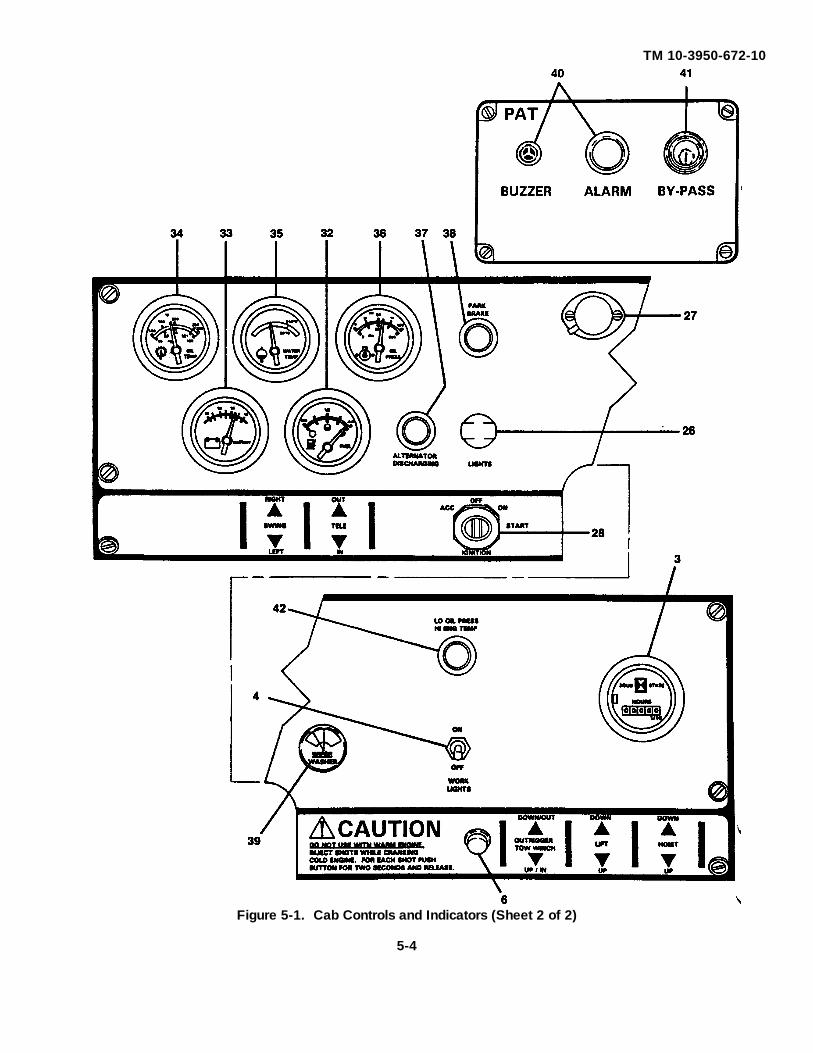
TM 10-3950-672-10
Figure 5-1. Cab Controls and Indicators (Sheet 2 of 2)
5-4

TM 10-3950-672-10
Legend for Figure 5-1.
1. Spotlight 23. Horn Button Switch2. Cab Circulating Fan 24. Fire Extinguisher3. Hourmeter (HOURS) 25. Turn Signal/Four Way Flasher4. Boom (WORK LIGHTS) Switch 26. LIGHTS Switch5. HOIST Control Lever 27. Panel Lamp6. COLD START Switch 28. IGNITION Switch7. Foot Throttle Pedal 29. Door Latch with Lock8. Foot Brake Pedal 30. TELEscope Control Lever9. OUTRIGGER Control Lever 31. SWING Control Lever10. LIFT Control Lever 32. FUEL Quantity Gauge11. 1-2-D-N-R Control Lever 33. Voltmeter (BATTERY)12. Level Indicator 34. Converter OIL TEMPerature Gauge13. Seat Slide Adjustment Lever 35. Engine WATER TEMPerature14. Seat Back Lumbar Support Knob Gauge15. Seat Belt 36. Engine OIL PRESSure Gauge16. Seat Height Adjustment Lever 37. ALTERNATOR DISCHARGING17. Dome Light Indicator18. Park Brake Lever 38. PARK BRAKE Indicator19. Heater/Defroster FAN Switch 39. Windshield WIPER/WASHER Switch20. Heater/Defroster Air TEMPerature 40. Two-block ALARM Indicator
Control 41. Two-block BY-PASS Switch21. OUTRIGGER SELECTOR Switch (R) 42. LOw OIL PRESSure/High ENGine22. OUTRIGGER SELECTOR Switch (L) TEMPerature Indicator
c. Lights Switch. The LIGHTS switch (26) is located on the main control panel to the left of the steering column.The switch is a push-pull-type switch with a rheostat control. The switch must be pulled to the second detent toilluminate the gauge lights on the console, the clearance lights, tail lights, and headlights. Rotating the switchknob controls the brightness of the panel gauge lights.
d. Panel Lamp. The panel lamp (27) is located on the top center of the main control panel. The switch (located atthe base of the lamp), is a two-position, on-off switch. Positioning the switch to ON energizes the lamp.
e. Dome Light. The dome light (17) is located on the left rear side of the cab. The light is illuminated by a switchon the light.
f. Windshield Wiper/Washer Switch. The windshield WIPER/WASHER switch (39) is located to the right of thesteering column on the main control panel. The switch has three positions corresponding to off, low speed, andhigh speed. Rotating the switch knob to the first detent energizes the wiper motor at low speed and rotating it tothe second detent energizes the motor at high speed. Rotating the switch knob to the counterclockwise positionstops the motor and causes the automatic park function of the wiper motor to return the wiper blade to the parkedposition. Pushing the switch knob energizes the motor on the windshield washer pump assembly.
5-5

TM 10-3950-672-10
g. Heater/Defroster Air Temperature Control. The heater/defroster air TEMP control (20) is located on the leftside of the cab beside the seat.
It is a push-pull cable control that positions the temperature control on the heater unit. Pull the control knob forwarm air and push it in for cool air.
h. Heater/Defroster Fan Switch. The heater/defroster FAN switch (19) is located on the left side of the cab besidethe seat to the rear of the heater/defroster air TEMP control. The switch controls the flow of air and has threepositions; OFF, HI, and LO.
i. Cab Circulating Fan. The cab circulating fan (2) is located on the dash on the right side of the cab. It ismounted to a ball joint so it can be directed to different parts of the cab.
j. Fire Extinguisher. The fire extinguisher (24) is retained in a bracket mounted below the main control panel onthe left side.
k. Spotlight. The spotlight (1) is located on the right side of the cab. It can be rotated 360 degrees and isilluminated by an on-off switch located on the spotlight handle.
I. Alternator Discharging Indicator. The ALTERNATOR DISCHARGING indicator (37) is a red flashing lightlocated on the main control panel to the left of the steering wheel. The light flashes whenever there is a failure inthe battery charging system.
m. Boom Light Switch. The boom light (WORK LIGHT) switch (4) is located on the lower right side of the maincontrol panel. The switch is an ON/OFF toggle switch that turns on the two work lights mounted on the boombase section.
n. Level Indicator. A level indicator is (12) installed on the right side of the cab in front of the shift lever. Theindicator provides the operator with a visual indication for determining the levelness of the machine.
o. Operator's Seat Controls. There are three adjustments for the operator's seat. The first is a lever (13) thatenables the seat to slide up and back. The second is a knob (14) which controls the seat back lumbar support.The third is a lever (1 6) to adjust the seat height. The seat features a seat belt (15) and a documentationstorage bag attached to the seat back.
p. Cab Door Latch and Lock. A keyed cab door latch and lock (29) can be used to secure the crane cab. Iflocking the cab door, be sure to slide the cab door window shut until the window locking mechanism latches.
5-1.3 Crane Controls and Indicators.
a. Foot Brake Pedal. The foot brake pedal (8) is located to the right of the steering column next to the acceleratorpedal. Depressing the pedal actuates a master cylinder that applies the hydraulic service brakes.
5-6

TM 10-3950-672-10
b. Park Brake Lever. The park brake lever (18) is located on the left side of the cab beside the seat. The leveroperates the parking brake by a control cable. Pushing down (forward) on the lever moves the control cable toapply the band brake on the transmission tailshaft. Pulling up (back) on the lever moves the cable to release theband brake on the transmission tailshaft. A pushbutton microswitch on the lever controls the PARK BRAKE light(38) on the main control panel.
c. 1-2-D-N-R Transmission Control Lever. The transmission control lever (11 ) is located on the right side of thecab in front of the level indicator. The lever has five positions; 1 (first or low gear), 2 (second gear), D (driveforward), N (neutral), and R (reverse).
d. Swing Control Lever. The swing control lever (31) is the leftmost lever on the left side of the main controlpanel. The lever when positioned to RIGHT or LEFT, actuates a control valve through linkage rods to provideswing in the desired direction.
e. Telescope Control Lever. The TELE control lever (30) is the first control lever to the left of the steering column.The lever when positioned to OUT or IN actuates a control valve through linkage rods to extend or retract theboom.
f. Outrigger Control Lever. The OUTRIGGER lever (9) is the first lever to the right of the steering column. Thelever when positioned to DOWN/OUT or UP/in actuates a control valve through linkage rods to position theoutrigger(s) as selected by the outrigger selection switch.
g. Outrigger Selector Switch. The OUTRIGGER SELECTOR (Right Side Outriggers) switch (21) is located on theleft side of the cab beside the seat. Positioning the lever to RIGHT FRONT or RIGHT REAR while operating theOUTRIGGER control lever chooses which right side outrigger is to be actuated.
h. Outrigger Selector Switch. The OUTRIGGER SELECTOR (Left Side Outriggers) switch (22) is located on theleft side of the cab beside the seat. Positioning the lever to LEFT FRONT or LEFT REAR while operating theOUTRIGGER control lever chooses which left side outrigger is to be actuated.
i. Lift Control Lever. The LIFT control lever (10) is located to the right of the steering column to the left of thehoist control lever. Positioning the lever to UP or DOWN actuates a control valve through linkage rods to raiseand lower the boom.
j. Hoist Control Lever. The HOIST control lever (5) is the right most control lever on the main control panel.Positioning the lever to DOWN or UP actuates a control valve through linkage rods to drive the hoist and raiseand lower the hoist cable.
5-7

TM 10-3950-672-10
k. Two-block Indicator. The two-block (ALARM) indicator (40) is in a panel located above the main control panel.The indicator is a red ALARM light that illuminates when the antitwo-block switch is actuated, indicating a twoblock condition. A BUZZER also sounds when the light illuminates. Refer to paragraph 4-2q for a more detaileddescription of the antitwo-block system operation.
l. Two-block Lockout Override. The two-block lockout override (BY-PASS) switch (41) is a two-position keyedswitch placarded NORMAL and OVERRIDE and is located to the right of the ALARM indicator light. With theswitch in NORMAL, two-block lockout will occur. With the switch in OVERRIDE, the lockout solenoid valve isenergized to open the valve and allow two-block lockout override.
m. Backup Alarm. (Not shown) The backup alarm is an audible alarm used to warn personnel when the crane isbacking up. The backup alarm system is electrical and consists of the backup alarm and associated wiring. Thealarm is connected into the backup light electrical wiring, and is activated when the backup light is used. Thebackup alarm is installed on the right rear side of the frame.
n. Park Brake Indicator. The PARK BRAKE indicator (38) is located on the left side of the main control panel. Apushbutton micro-switch located on the park brake lever lights the indicator if the park brake is engaged.
5-2. PREVENTIVE MAINTENANCE CHECKS AND SERVICES (PMCS).
5-2.1 General.
a. Before you operate. Always keep in mind the CAUTIONS and WARNINGS.Perform your before (B) PMCS.
b. While you operate. Always keep in mind the CAUTIONS and WARNINGS.Perform your during (D) PMCS.
c. After you operate. Be sure to perform your after (A) PMCS.
d. If your equipment fails to operate. Troubleshoot with the proper equipment.Report any deficiencies using the proper forms. See TM 38-750.
5-2.2 Procedure.
PMCS procedures in the table are intended to insure that the crane is ready to be operated safely with minimumcrane wear and tear.
The PMCS table lists the checks and services that need to be performed at various intervals. The intervals weredetermined by crane design and expected use.
a. "Before" or (B) PMCS shall be performed by the operator prior to starting the engine and attempting to operatethe crane.
5-8

TM 10-3950-672-10
b. "During" or (D) PMCS shall be performed while operating the crane both while sitting in the cab manipulating thecontrols and when outside the cab doing other tasks associated with operations.
c. "After" or (A) PMCS shall be performed after crane operation and when it is being shut down for a period of time.
d. "Weekly" or (W) PMCS need not be performed every day or every time the crane is operated, but must be donerelatively frequently, and not delayed or forgotten. A weekly routine must be established to check and servicethese items.
e. "Monthly" or (M) PMCS provides checks and services that need not be done weekly but cannot be ignored morethan a month. A monthly service routine must be established.
f. There are checks and services that must be done on the basis of the number of hours of engine operation, orbased on special environmental conditions. These more frequent checks are marked with an asterisk. Anappropriate footnote explains the special service interval.
5-2.3 Additional Special Checks and Services.
Perform weekly (W) as well as before (B) operations PMCS if:
a. You are the assigned operator and have not operated the crane since the last weekly.
b. You are operating the crane for the first time.
5-2.4 Leakage Definitions.
Leakage definitions for operator/crew PMCS shall be classified as follows:
Class I Seepage of fluid (as indicated by wetness or discoloration) not great enough to form drops.
Class II Leakage of fluid great enough to form drops but not enough to cause drops to drip from item beingchecked/inspected.
Class III Leakage of fluid great enough to form drops that fall from the item being checked/inspected.
CAUTION
Equipment operation is allowable with minor leaks (Class I or II). Of course, you mustconsider the fluid capacity in the item/system being checked/inspected. When in doubt,notify your supervisor.
5-9
TM 10-3950-672-10
When operating with Class I or II leaks, continue to check fluid levels as required in your PMCS.
Class III leaks should be reported to your supervisor or organizational maintenance.
5-2.5 Equipment Not Ready If:
This column provides a clear description of the conditions in which the crane shall not ever, unequivocally, beoperated, due to personnel safety and/or prospect of equipment damage.
Deficiencies in the crane and its performance shall be reported to your supervisor, and/or to your organizationalmaintenance group on Form 2408-X as well as noted in the Equipment Daily Log, Form 2408-1.
PMCS can be performed by the operator without removing any assemblies.
5-2.6 General Safety Precautions.
It is impossible to compile a list of safety precautions covering all situations. However, there are basic safetyprecautions that MUST be followed during your daily routine. Safety is YOUR PRIME RESPONSIBILITY, since anypiece of equipment is only as safe AS THE PERSON AT THE CONTROLS.
With this thought in mind, Section 2 of the operator's manual will assist you, the operator, in promoting safeworking atmosphere for yourself and those around you. It is not meant to cover every conceivable circumstance whichcould arise. It is intended to present basic safety precautions that should be followed in daily operation.
Because you, the operator, are the only part of the crane that can think and reason, your responsibility is notlessened by the addition of operational aids or warning devices. Indeed, you must guard against acquiring a false senseof security when using them. They are there to assist, NOT direct the operation. Operational aids or warning devicescan be mechanical, electrical, electronic, or a combination thereof. They are subject to failure.
You, the operator, are the only one who can be relied upon to assure the safety of yourself and those around you.Be a PROFESSIONAL and follow the RULES of safety.
REMEMBER, failure to follow just one safety precaution can cause an accident to people and equipment.
You are responsible for the safety of yourself and of those around you.
Ensure you and those working with you are aware of any special dangers where you are operating the crane. Beespecially careful of dangerous ground and objects, including buildings, near the crane.
Be aware at all times that you are responsible for the safety of yourself, your coworkers, the crane, andeverything around it. Make certain the crane is properly maintained, and then pay attention to winds, boom deflections,rope sway, and any unusual things, which you, as a crane operator, may notice which would not be important to others.
5-10

TM 10-3950-672-10
Know and abide by the basic safety rules.
Read and understand the Operator's Manual before entering the cab.
Follow directions on all placards. Know what they mean and follow their instructions.
Operators must be thoroughly familiar with safe crane operating practices and have a complete understanding ofall operation and maintenance instructions provided. Operators should be physically fit and thoroughly trained, withrelated experience, not be easily excitable, not be subject to epileptic seizures, and not be using any drug that couldimpair physical, visual, or mental reactions or capabilities.
Wear the proper clothing for the job. Wear personnel protective equipment as required by local or jobregulations.
Inspect the crane every day (before the start of each shift). Ensure that routine maintenance and lubrication arebeing dutifully performed. Do not operate a damaged or poorly maintained crane. You risk lives when operating faultymachinery, including your own.
5-2.7 Diesel Fuel Recommendations/Specifications
WARNING
Do not mix gasoline or alcohol with diesel fuel. This mixture can cause an explosion.
NOTE
Any adjustment to compensate for reduced performance with a fuel system using alternatefuel is not warrantable. Also, wear on any midrange fuel pump component attributed to thelack of lubrication in the fuel is not a warrantable repair.
Use ASTM No. 2-D fuel with a minimum Cetane number of 40. No. 2 diesel fuel gives the best economy andperformance under most operating conditions. Fuels with Cetane numbers higher than 40 may be needed in highaltitudes or extremely low ambient temperatures to prevent misfires and excessive smoke. At operating temperaturesbelow 32°F (0°C), use a blend of No. 1-D and No. 2-D fuels, also known as "winterized" No. 2-D.
Use low sulfur content fuel having a cloud point that is at least 10 degrees below the lowest expected fueltemperature. Cloud point is the temperature at which crystals begin to form in diesel fuel. The viscosity of the fuel mustbe kept above 1.3 centistokes to provide adequate fuel system lubrication at 104°F (40°C).
Acceptable Alternate Fuel Types: No. 1-D Diesel and No. 2 Fuel OilAcceptable Alternate Fuel Types (if 5% new lube oil No. 1-K Kerosene, No. 2-K Kerosene,
is blended with these fuels to increase the lubricity): Jet-A, Jet A-1, JP-5, and JP-8Unacceptable Fuel Types: Jet-B, JP-4, and Cite
5-11
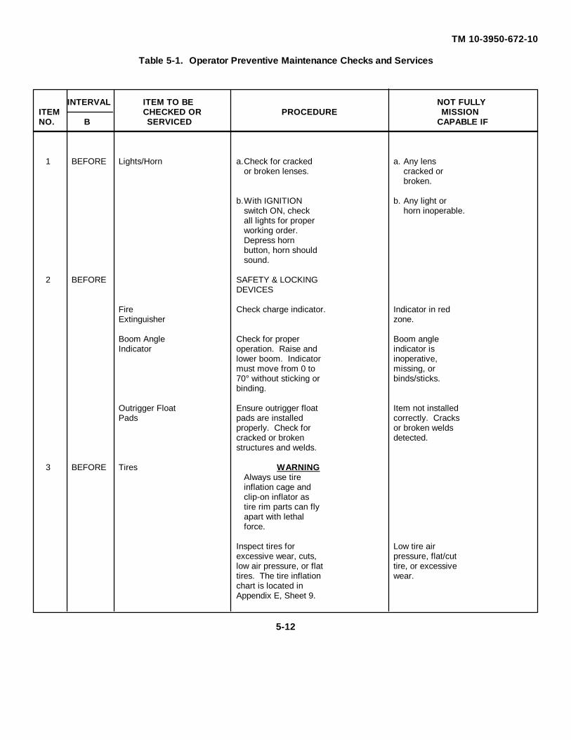
TM 10-3950-672-10
Table 5-1. Operator Preventive Maintenance Checks and Services
INTERVAL ITEM TO BE NOT FULLYITEM CHECKED OR PROCEDURE MISSIONNO. B SERVICED CAPABLE IF
1 BEFORE Lights/Horn a.Check for cracked a. Any lensor broken lenses. cracked or
broken.
b.With IGNITION b. Any light orswitch ON, check horn inoperable.all lights for properworking order.Depress hornbutton, horn shouldsound.
2 BEFORE SAFETY & LOCKINGDEVICES
Fire Check charge indicator. Indicator in redExtinguisher zone.
Boom Angle Check for proper Boom angleIndicator operation. Raise and indicator is
lower boom. Indicator inoperative,must move from 0 to missing, or70° without sticking or binds/sticks.binding.
Outrigger Float Ensure outrigger float Item not installedPads pads are installed correctly. Cracks
properly. Check for or broken weldscracked or broken detected.structures and welds.
3 BEFORE Tires WARNINGAlways use tireinflation cage andclip-on inflator astire rim parts can flyapart with lethalforce.
Inspect tires for Low tire airexcessive wear, cuts, pressure, flat/cutlow air pressure, or flat tire, or excessivetires. The tire inflation wear.chart is located inAppendix E, Sheet 9.
5-12

TM 10-3950-672-10
Table 5-1. Operator Preventive Maintenance Checks and Services Continued
INTERVAL ITEM TO BE NOT FULLYITEM CHECKED OR PROCEDURE MISSIONNO. B SERVICED CAPABLE IF
4 BEFORE Antifreeze & WARNINGCoolant The cooling system is
pressurized. Personalinjury may result whenremoving the radiatorcap after operatingtemperature is reached.Do not remove radiatorcap when radiator ishot to touch.
a.Check for proper a. Coolant levelcoolant level (HOT low; Class IIIor COLD) on coolant leaks exist.recovery tank giventhe enginetemperature.
b.Inspect radiator b. Hoses/clampshoses and clamps damaged, loose,for damage, or missing;security, and Class III leaksevidence of leaks. exist.
5-13

TM 10-3950-672-10
Table 5-1. Operator Preventive Maintenance Checks and Services Continued
INTERVAL ITEM TO BE NOT FULLYITEM CHECKED OR PROCEDURE MISSIONNO. B SERVICED CAPABLE IF
5 BEFORE Transmission Check for correct fluid Transmission fluidlevel on transmission level low; Class IIIfluid dipstick with leaks exist.engine running atnormal operatingtemperature. The"Hot" reading shouldhave the fluid level inthe cross-hatched area.The "Cold" readingshould have the fluidlevel between the twoholes punched in thedipstick.
6 BEFORE Engine Check engine Engine oil levelCrankcasecrankcase oil level. low; Class III leaksMaintain oil level within exist.cross-hatched area ondipstick (betweenarrows).
5-14

TM 10-3950-672-10
Table 5-1. Operator Preventive Maintenance Checks and Services Continued
INTERVAL ITEM TO BE NOT FULLYITEM CHECKED OR PROCEDURE MISSIONNO. B SERVICED CAPABLE IF
7 BEFORE Hydraulic CAUTIONReservoir & Ensure all hydraulicFilter cylinders are fully
retracted whenchecking hydraulic fluidlevel.
a.Check sight gage Hydraulic oil level(on front o f low; Class III leakshydraulic tank) for exist.proper oil level.Ensure that oil isvisible half-way upsight gage.Reservoir capacity is35 gallons; gagelevel is 30 gallons.
b.Check condition of b. Red flaghydraulic oil filter appears.indicator located onthe filter head. Redflag indicates fouledfilter element.
c.Inspect hydraulic c. Hydraulic tanktank breather for breather iscleanliness and fouled or loose.security.
8 BEFORE Air Cleaner a.Check condition of a. Red flagair filter indicator appears.located in air intakepiping. Red flagindicates fouledfilter element.
b.Inspect filter b. Filter housing,housing, air intake air intakepiping, and all piping, and/orclamps for damage clampsand security. damaged, loose,
or missing.
5-15

TM 10-3950-672-10
Table 5-1. Operator Preventive Maintenance Checks and Services Continued
INTERVAL ITEM TO BE NOT FULLYITEM CHECKED OR PROCEDURE MISSIONNO. B SERVICED CAPABLE IF
9 BEFORE Hydraulic Oil Inspect hydraulic oil Hydraulic oil coolerCooler cooler for evidence of contaminated or
leaks and dirt leaks.restricting air flowthrough cooler.
10 BEFORE Wire Rope a.Inspect wire rope, a. Refer torope sockets, and paragraph 2-4fittings for damage, for wire ropewear, corrosion, safety criteria.heat damage, andlack of lubrication.Ensure that allcomponents areproperly installedand secure.
b.Inspect sheave b. Any componentguards, guides, damaged and/ordrums, flanges, and corroded.other surfaces thatcome in contactwith wire rope forsharp edges, burrs,and corrosion thatcould damage wirerope.
11 BEFORE Boom Sheaves a.Inspect boom a. Any component& Hook Block sheaves and hook loose, damaged,
block to ensure all or not installedcomponents are properly.properly installedand secure.
b.Inspect hook block b. Hook blockfor cracks, damage, cracked,and deformed hook. damaged, ordeformed.
c.Inspect boom and c. Excessive dirt,boom nose sheaves grease, orfor excessive dirt, foreign matter.grease, and foreignmatter.
5-16

TM 10-3950-672-10
Table 5-1. Operator Preventive Maintenance Checks and Services Continued
INTERVAL ITEM TO BE NOT FULLYITEM CHECKED OR PROCEDURE MISSIONNO. B SERVICED CAPABLE IF
12 BEFORE Hoist Drum and a.Check for proper a. ChatteringMotor operation while detected.
operating machineby attaching a testweight to the hookblock. Then raiseand lower loadseveral times.Ensure hoist motorand brake operatesmoothly.
b.Inspect hoist b. Any damage,hydraulic lines for loose, or leakingdamage, security, component;and evidence of Class III leakleaks. exists.
13 BEFORE Windshield a.Check for proper a. Wiper motorWipers & operation. inoperable.Washer Bottle
b.Check fluid level inwindshield washerbottle.
14 BEFORE Seat Belt Check seat belt for Seat belt worn,wear, tears, and damaged, orcondition of locking inoperable.device.
5-17

TM 10-3950-672-10
Table 5-1. Operator Preventive Maintenance Checks and Services Continued
INTERVAL ITEM TO BE NOT FULLYITEM CHECKED OR PROCEDURE MISSIONNO. B SERVICED CAPABLE IF
15 BEFORE Fuel Tank and Inspect fuel tank and Any fuel systemLines lines for damage, component
security and evidence damaged, loose, orof leaks. leaking; Class II
leak exists.
16 BEFORE Fuel Water Drain water andSeparator sediment from fuel-
water separator asfollows:
a.Open fuel filter/fuel-water separatoraccess panellocated in right rearwheel well.
b.Loosen valve onfuel-water separatorfour complete turnsuntil valve dropsdown one inch.Drain water andsediment until clearfuel is visible.
CAUTIONDo not overtightenvalve as it may bedamaged.
c.Tighten to closedrain valve. Thenclose access panelunder wheelwell.
5-18

TM 10-3950-672-10
Table 5-1. Operator Preventive Maintenance Checks and Services Continued
INTERVAL ITEM TO BE NOT FULLYITEM CHECKED OR PROCEDURE MISSIONNO. B SERVICED CAPABLE IF
17 DURING Backup Alarm Check for proper Backup alarmoperation. inoperable.
18 DURING Main Control Check all main controlPanel Gages panel gages for
operation and properreadings as follows:
a.OIL PRESS gage. a. Oil pressureNormal gage reading lower than 10is 10 psi at idle. (35 psi.psi at high idle and85 psi at maximumgoverned speed)
b.WATER TEMP gage. b. Gage reads inNormal gage reading red area.is in green area.
c.Converter OIL TEMP c. Gage reads ingage. Normal gage red area.reading is in greenarea.
d.Voltmeter d. Gage reads(BATTERY) gage. outside ofNormal reading is acceptable12 to 14 volts.limits.
19 DURING Brakes, Service NOTE& Parking Ensure outriggers
are retracted.
a.Park brake. With a. Any vehiclepark brake lever movement withapplied, check for park brakeforward and reverse applied.motion of vehicle.
b.Service brakes. b. Chattering,Check/listen for grinding, ornoise and stopping inability to stop.ability with cranemoving slowly (ineither direction)when depressingservice brake pedal.
5-19

TM 10-3950-672-10
Table 5-1. Operator Preventive Maintenance Checks and Services Continued
INTERVAL ITEM TO BE NOT FULLYITEM CHECKED OR PROCEDURE MISSIONNO. B SERVICED CAPABLE IF
SAFETY & LOCKINGDEVICES
20 DURING Control Levers Check for proper Any control lever& Linkage operation of all control or pedal fails to
levers and pedals. operate.Verify that all controlsoperate withoutbinding.
21 DURING Swing Brake Check for proper Superstructureoperation of automatic continues to moveswing brake. with swing lever in
neutral position.Chattering,grinding, orinability to stop.
22 DURING Antitwo-Block CAUTIONSystem Do not allow the
hook block tocontact the lowerboom nose sheave.
Check for proper Antitwo-blockoperation of the system inoperableantitwo-block systemby slowly raising theempty hook block untilit contacts weightsuspended from boomnose. Verify that hoist'cannot be raised.
23 DURING Steering Check steering for Steering wheelsmooth and proper binds or turnsoperation. rough.
24 WEEKLY Battery WARNINGDo not smoke orallow flame or sparkin the vicinity whilechecking thebattery. Thebattery generateshydrogen, a highlyexplosive gas.
5-20
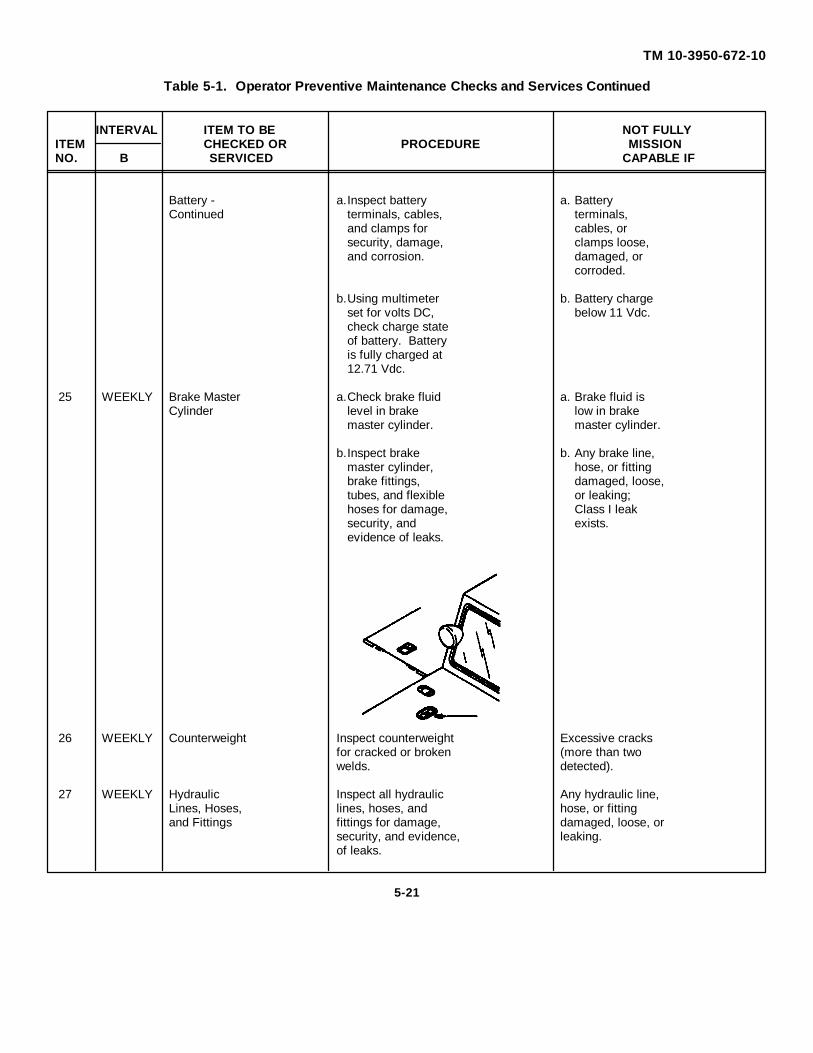
TM 10-3950-672-10
Table 5-1. Operator Preventive Maintenance Checks and Services Continued
INTERVAL ITEM TO BE NOT FULLYITEM CHECKED OR PROCEDURE MISSIONNO. B SERVICED CAPABLE IF
Battery - a.Inspect battery a. BatteryContinued terminals, cables, terminals,
and clamps for cables, orsecurity, damage, clamps loose,and corrosion. damaged, or
corroded.
b.Using multimeter b. Battery chargeset for volts DC, below 11 Vdc.check charge stateof battery. Batteryis fully charged at12.71 Vdc.
25 WEEKLY Brake Master a.Check brake fluid a. Brake fluid isCylinder level in brake low in brake
master cylinder. master cylinder.
b.Inspect brake b. Any brake line,master cylinder, hose, or fittingbrake fittings, damaged, loose,tubes, and flexible or leaking;hoses for damage, Class I leaksecurity, and exists.evidence of leaks.
26 WEEKLY Counterweight Inspect counterweight Excessive cracksfor cracked or broken (more than twowelds. detected).
27 WEEKLY Hydraulic Inspect all hydraulic Any hydraulic line,Lines, Hoses, lines, hoses, and hose, or fittingand Fittings fittings for damage, damaged, loose, or
security, and evidence, leaking.of leaks.
5-21

TM 10-3950-672-10
Table 5-1. Operator Preventive Maintenance Checks and Services Continued
INTERVAL ITEM TO BE NOT FULLYITEM CHECKED OR PROCEDURE MISSIONNO. B SERVICED CAPABLE IF
28 WEEKLY Fan Belts Inspect fan belt for Damaged or loose.loose, broken, cracked,or frayed condition.Belt should deflectapproximately 1/2 in. atmidspan betweenpulleys.
29 MONTHLY Hydraulic Inspect all hydraulic Cracks or brokenCylinders and cylinders for damage, components; looseValves security, and evidence or missing
of leaks. Check for attachingcracked or broken hardware; Class IIIvalve/cylinder bodies leaks exist.and mountingstructures includingworn, loose, or missingpivot pins and otherattaching hardware.
30 MONTHLY Boom a.Inspect boom for a. Cracked orcracked or broken broken welds orwelds and bends/ distortiondistortion of boom noted.sections.
b.Inspect boom wear b. Worn,pads for damage, damaged, loose,wear, security, and or unlubricatedlack of lubrication. boom wearpads.
31 MONTHLY Exhaust Inspect muffler, Any exhaustSystem exhaust pipes, and system component
clamps for damage, damaged, loose, orsecurity, and corrosion. corroded.
5-22
TM 10-3950-672-10
5-3. OPERATING PROCEDURES.
5-3.1 Normal Engine Starting.
WARNING
Before starting the engine, ensure the parking brake is applied.
CAUTION
Never crank the engine for more than 30 seconds during an attempted start. If the enginefails to start after 30 seconds, allow the starter motor to cool for approximately two minutesbefore attempting another start.
NOTE
The engine will not crank unless the 1-2-D-N-R lever (11, Figure 5-1) is in the neutral (N)position.
(a) Turn the IGNITION switch (28) to START and release immediately when the engine starts.
(b) Check engine instruments for proper indications.
CAUTION
If oil pressure and/or temperature indicator(s) do not display proper readings, shut down theengine and correct the malfunction before resuming operation.
(c) Allow the engine and hydraulic oil to warm up at least five minutes before applying a load.
NOTE
Gauge readings are given as a guide only. Readings may be slightly higher or lowerdepending on the individual engine condition. If in doubt, refer to the applicable engineservice or operation manual.
5-23

TM 10-3950-672-10
5-3.2 Cold Weather Starting.
CAUTION
Avoid overloading the air intake manifold with highly volatile starting fluid while attempting tostart the engine using the COLD START button (6, Figure 5-1). Do not attempt more thatthree consecutive cold weather starts without first allowing the starting fluid in the air intakemanifold to dissipate. Failure to follow this caution could result in overloading the air intakemanifold with starting fluid which could result in a minor explosion and damage to the engine.
NOTE
The correct grade of oil for the prevailing temperature should be used in the crankcase toprevent hard cranking.
NOTE
Diesel fuel should have a pour point of 10°F (-12°C) less than the lowest expectedtemperature. In case of emergency, white kerosene may be added to the fuel to bring thepour point down to the required temperature to prevent clogging of filters and small passagesby wax crystals. The addition of kerosene is NOT recommended for general use. If lowtemperatures are ONLY expected at startup, it is advisable to use starting aids such aspreheating, starting fluid metering equipment, or starting fluid spray application into the aircleaner intake.
a. To start the engine, place the IGNITION switch (28, Figure 5-1) to the START position and push the COLDSTART button (6) for two seconds and release.
b. If the engine does not start within 30 seconds, allow the starter to cool for approximately two minutes andrepeat the procedure.
5-3.3 Shutdown Procedure.
a. Allow the engine to operate at fast idle speed for approximately five minutes to avoid high internal heatrise and allow for heat dissipation.
5-24

TM 10-3950-672-10
NOTE
If the IGNITION switch (28, Figure 5-1) does not shut down the engine, turn the fuel off at thefuel supply shutoff valve located at the fuel tank.
b. Position the IGNITION switch (28) to the OFF position.
5-3.4 Crane Travel Operation. The crane is primarily designed for yard and close proximity areas. Design andapplication intent precludes operation on public highways; however, many jurisdictions permit limited travel undercontrolled conditions. Consult local vehicular codes and regulations in your area.
WARNING
Do not travel with an empty hook in a position where it can swing freely. Always secure anempty hook to the tiedown provided on the front of the crane (see cover illustration).
WARNINGAvoid holes, rocks, extremely soft surfaces, and any other obstacles which might subject thecrane to undue stresses or possible overturn.
WARNINGOn open ground, tow or pull only on the pintle hooks or lift/tow lugs.
CAUTION
For extended travel, check the cold tire pressure prior to start. (Refer to tire inflation chart inAppendix E, sheet 9.) Regardless of ambient temperature, after every two hours of traveltime, stop and allow the tires to cool off for at least a 30 minute period. At destination, thetires must be allowed to cool to ambient temperature before crane lifting on rubber.
CAUTION
Do not drive the crane with the lift cylinder bottomed. Position the boom to just abovehorizontal.
5-25

TM 10-3950-672-10
CAUTION
Should the crane become mired down, use a tow truck or tractor to free the vehicle. Severedamage to the transmission or axles may occur if the operator attempts to free the craneunassisted.
CAUTION
If the crane is mired down, use the lugs to pull or tow. There are two lift/tow lugs available oneach end of the crane. When using these lugs, always tow or pull using both lugs.
5-3.5 Driving the Crane. The following operating conditions should be strictly adhered to before moving the crane.Procedures for accomplishing the following can be found in the various Sections of this manual.
a. Ensure the boom is fully retracted. Refer to paragraph 5-3.15.
b. Swing the boom over-the-front and lower the boom to just above horizontal. Refer to paragraph 5-3.11.
c. Remove the hook block and stow securely before traveling or ensure the hook block is properly secured tothe tie down provided for that purpose. Refer to illustration of crane on front cover.
d. Ensure the outriggers are fully retracted. Refer to paragraph 5-3.10.
e. Apply foot brake pedal (8, Figure 5-1) then release parking brake by pulling up on lever (18).
f. Using 1-2-D-N-R lever (11, Figure 5-1), select D (Drive forward) or R (reverse).
g. Release foot brake pedal (8, Figure 5-1) and depress foot throttle pedal (7).
h. Steer crane in a manner similar to that of an automobile.
i. To stop, release foot throttle pedal (7, Figure 5-1) and depress foot brake pedal (8).
5-26

TM 10-3950-672-10
NOTE
If there is a hydraulic power failure, the crane can still be steered, because the steeringcontrol valve acts as a pump when the steering wheel is turned. However, steering in thismanner is very difficult. If this failure should occur, immediately bring the crane to a safestop and proceed with immediate repairs or replacement.
5-3.6 General Crane Operation. The control lever operation for crane functions is standard, i.e., the closer the leveris to neutral (center), the slower the system responds. This applies to both forward and rear movement of the applicablelever. The control lever should be returned to neutral to hold the load.
CAUTION
Never feather the hoist control to hold the load.
NOTE
Always operate the control lever with slow, even pressure.
5-3.7 Functional Check. After the crane has been readied for service, a functional check of all craning functions (withno load applied) should be performed.
WARNING
Carefully read and become familiar with all crane operating instructions before attempting tooperate the crane.
a. Operate the engine at or near the governed RPM during performance of all crane functions.
b. Extend and set the outriggers. Refer to paragraph 5-3.9.
c. Raise, lower, and swing the boom right and left a minimum of 45 degrees. Refer to paragraphs 5-3.11, 5-3-12, and 5-3-13.
d. Telescope the boom in and out. Refer to paragraphs 5-3.14 and 5-3-15.
e. Raise and lower the hoist cable a few times at various boom lengths. Check for kinks in the cable. Referto paragraphs 5-3.16 and 5-3.17.
5-27

TM 10-3950-672-10
5-3.8 Using Load Chart.
NOTE
One of the most important tools of every crane is the load chart found in the operator's cab.Refer to Figure 5-2 as required.
The load chart contains a large amount of information, which must be thoroughly understood by the operator.
The load chart contains a Range Diagram, Lifting Area Diagrams, one On Outriggers Chart, and one On RubberCapacity Chart.
The capacity charts are divided into capacities limited by structural strength and capacities limited by stability.This is shown by the bold line across the chart. Capacities above the line are limited by structural strength and capacitiesbelow the line are limited by crane stability.
Another important section of the load chart is the range diagram. The range diagram illustrates the tip heightwhich can be achieved at each boom length, angle, and radius. If the operator knows the radius required for a specificlift and the tip height necessary, he can calculate the required boom length and angle needed for the lift. He then checksthe capacity chart for the specific boom length and radius to find out if the crane is capable of performing the lift safely.Or, on the other hand, if the boom length and angle are known, the radius can be determined from the range diagram.
Figure 5-2. Terms to Know When Using Load Chart
5-28

TM 10-3950-672-10
A lifting area diagram is included as part of the load chart to describe over side, over rear, and over front liftingareas. An examination of the lifting area diagram shows that the locations of the outriggers in the fully extended positionare used to mark the boundaries of the lifting areas.
The last major portion of the load chart is the section concerning notes to lifting capacities. Be sure to read allnotes carefully so you understand what each one means. The load chart also gives weight reductions for Grove loadhandling devices such as hook blocks, headache balls, boom extension section, etc., which must be taken intoconsideration as part of the load. Remember, any other load handling devices such as chains, slings, or spreader barsmust also be considered, and the weight of these devices must be added to the weight of the load.
NOTE
The information in the following paragraph is an example of how to compute a lift, but thenumbers used in the example may not coincide with the load chart in the cab.
To understand the uses of the load chart, a typical example of a lifting problem is offered. Determine whether ornot the lift can be made safely. The problem is to lift an air conditioning unit weighing 2,350 lbs (1,066 kg), which issecured by bolted wood blocking and located between aisles of outside storage. The air conditioning unit is to be loadedon a flat bed truck located in an open loading area 50 ft (15.24 m) from the storage area. Further, the distance betweenthe aisles prevent performing the lifting operation with the crane on outriggers. The crane is equipped with the 10.6 to 24ft (3.0 to 7.3 m) three-section boom. By measuring the center of the load, in relation to the center line of rotation of thecrane, the radius is determined to be 18 ft (5.4 m). Checking the load charts in the crane cab indicates that 3,000 lbs(1,360.8 kg) may be safely lifted at an 18 ft (5.4 m ) radius.
NOTE
The weights of all load handling devices are considered part of the load lifted and suitableallowances for them should be made.
A sling and spreader bar are also required to perform the lift; therefore, it is mandatory that the combinationweight be added to the unit being lifted. The new total weight is now 2,425 lbs (1,000 kg). A double check of the loadchart reveals the lift may still be made safely. Although this lift may be performed with reasonable ease, a good craningpractice may be exercised by extending and setting the outriggers if equipped when hoisting the load onto the flat bedtruck.
5-29

TM 10-3950-672-10
5-3.9 Setting the Outriggers.
WARNING
The outriggers must be set before any other operation of the crane is attempted, unless liftingon rubber. Failure to comply could result in injury or death.
a. Position OUTRIGGER control lever (9, Figure 5-1) to DOWN.
b. Position OUTRIGGER SELECTOR switches (21 and 22) to the desired position(s) and hold until theoutriggers are fully extended, tires clear the ground, and the crane is level as indicated by the levelindicator, Figure 5-3.
c. Return OUTRIGGER control lever (9) and OUTRIGGER SELECTION switches (21 and 22) to their neutralpositions.
Figure 5-3. Crane level Indicator
5-3.10 Stowing the Outriggers.
a. Position OUTRIGGER control lever (9, Figure 5-1) to UP.
b. Position OUTRIGGER SELECTION switches (21 and 22) to the desired position(s) and hold until theoutriggers are fully retracted.
c. Return OUTRIGGER control lever (9) and OUTRIGGER SELECTION switches (21 and 22) to their neutralpositions.
5-30

TM 10-3950-672-10
5-3.11 Swinging the Boom.
WARNING
Before initiating any swing operations, make certain the area in the swing path of the hookblock and/or load as well as the tail swing area, is clear of all obstructions. Failure to complycould result in injury or death.
WARNING
When swinging the load from over-the-front to over-the-side of the crane, refer to the over-the-side load chart to make certain the applicable capacity is not exceeded. Traveling withany load over-the-side is prohibited.
CAUTION
Never push or pull the SWING control lever (31, Figure 5-1) through neutral to the oppositedirection to stop swing motion.
NOTE
Always operate the control lever with a slow, even pressure.
a. To swing boom RIGHT, push SWING control lever (31) forward (away from the operator). To swing LEFT,pull back (toward the operator).
b. To stop boom swing, return SWING control lever (31) to its neutral position which automatically sets theswing brake.
5-3.12 Elevating the Boom.
WARNING
Before elevating the boom, ensure the area above and beneath the boom is clear of allobstructions and personnel.
a. To elevate boom, pull LIFT control lever (10, Figure 5-1) back (toward the operator) to the UP position, andhold until the boom reaches the desired elevation angle.
b. To stop boom elevation, return LIFT control lever (10) to its neutral position.
5-31

TM 10-3950-672-10
5-3.13 Lowering the Boom.
WARNING
Before lowering the boom, make certain the area beneath the boom is clear of allobstructions and personnel.
WARNING
Long cantilever booms can create a tipping condition even when unloaded and in anextended and lowered position.
WARNING
When lowering the boom, lower the cable at the same time to prevent two-blocking the boomnose and the hook block.
WARNING
The closer the load is carried to the boom nose, the more important it becomes to let outhoist cable as the boom is lowered.
a. To lower boom, push LIFT control lever (10, Figure 5-1) forward (away from the operator) to DOWNposition and hold until boom is lowered to desired position.
b. To stop boom, return LIFT control lever (10) to its neutral position.
5-3.14 Extending the Boom.
WARNING
When extending the boom, let out cable simultaneously to prevent two-blocking the boomnose and hook block.
WARNING
Check the load chart for maximum load at given radius, boom angle, and length beforeextending boom with a load.
5-32

TM 10-3950-672-10
a. To extend boom, push TELE control lever (30, Figure 5-1) (away from the operator) to OUT position andhold until the boom extends to desired length.
b. To stop boom extension, return TELE control lever (30) to its neutral position.
5-3.15 Retracting the Boom.
WARNING
When retracting the boom, the load will lower unless the hoist cable is taken insimultaneously.
a. To retract boom, pull TELE control lever (30, Figure 5-1) (toward the operator) to IN position and hold untilboom retracts to desired length.
b. To stop boom, return TELE control lever (30) to its neutral position.
5-3.16 Lowering Hoist Cable.
WARNING
Before lowering or raising the load, ensure the area beneath the load is clear of allobstructions and personnel.
CAUTION
When starting or stopping the hoist, do not jerk the HOIST control lever (5, Figure 5-1).Jerking the lever causes the load to bounce, which could result in possible damage to thecrane.
NOTE
When the load is stopped at the desired height, the automatic brake will engage and hold theload as long as the control lever remains in neutral.
a. To lower hoist cable, push HOIST control lever (5) forward (away from the operator) to DOWN position andhold until the hook or load is lowered to the desired height.
b. To stop hoist cable, return HOIST control lever (5) to its neutral position. This automatically sets the hoistbrake.
5-33

TM 10-3950-672-10
5-3.17 Raising the Hoist Cable.
a. To raise hoist cable, pull the HOIST control lever (5, Figure 5-1) back (toward the operator) to UP positionand hold until hook or load is raised to desired height.
b. To stop hoist cable, return HOIST control lever (5) to its neutral position.
5-3-18 Emergency Load Lowering Procedures. The following procedure will be used to lower a load suspended in theair after a major powertrain or hydraulic system failure after which, the hoist has become inoperable. This procedure willprovide hydraulic pressure to override the hoist brake mechanism allowing the load to slowly lower to the ground.
LATER
5-3.19 Recommended Crane Shutdown Procedures. The following procedure will extend the service life of variouscrane components, reduce vandalism and accidents during crane shutdown periods or anytime the crane is leftunattended.
WARNING
Never park the crane near holes, or on rocky or extremely soft surfaces. This may cause thecrane to overturn, resulting in injury to personnel.
a. Remove load from hook block.
b. Remove or stow all jibs or boom extensions.
c. Fully retract the boom.
d. Lower boom to normal travel position.
e. Retract all outriggers.
f. Park crane on a flat stable surface.
g. Apply parking brake and chock wheels.
h. Ensure all operating controls are in their neutral positions.
CAUTION
Allow the engine to idle from 3 to 5 minutes after a full-load operation before shutting it down.This will allow the engine to cool down gradually and uniformly.
5-34

TM 10-3950-672-10
i. After cool down period, shut down engine by turning IGNITION switch (28, Figure 5-1) to OFF.
j. Remove ignition key.
k. Close and latch sliding cab door window. Then close and lock cab door.
l. Close and secure all frame access covers.
5-3.20 Operating Cab Heater.
NOTE
The cab heater has air ducts that release air both under the operator's seat and above themain control panel (to defrost the windshield). The air flow through both ducts is controlledby the FAN knob.
a. Turn FAN knob (19, Figure 5-1) to control the speed of the fan.
b. Pull air TEMP control knob (20) for warm air and push the knob in for cool air.
5-35/(5-36 blank)

TM 10-3950-672-10
SECTION 6
MAINTENANCE INSTRUCTIONS
6-1. LUBRICATION INSTRUCTIONS.
6-1.1 General. Following the designated lubrication procedures is important in ensuring maximum cranelifetime and utilization. The procedures and lubrication charts in this section include information on the types oflubricants used, the location of the lubrication points, the frequency of lubrication, and other information.
The service intervals specified are for normal operation where moderate temperature, humidity, andatmospheric conditions prevail. In areas of extreme conditions, the service periods and lubrication specifications shouldbe altered to meet existing conditions. For information on extreme condition lubrication, contact your local servicerepresentative or Grove Customer Services, Chambersburg, Pennsylvania.
CAUTION
Chassis grease lubricants must not be applied withair pressure devices as this lubricant is used onsealed fittings.
CAUTION
The multipurpose grease used during manufactureis lithium based. Use of a non-compatible greasecould result in damage to equipment.
Specific recommendations of brand and grade of lubricants are not made here due to regional availability,operating conditions, and the continual development of improved products. Where questions arise, refer to thecomponent manufacturer's manual and a reliable supplier.
6-1.2 Lubrication Symbols. Symbols and descriptions used throughout this section are as follows:
EP-MPG. Extreme Pressure Multipurpose Grease. This is a lithium soap base grease with a high loadcarrying capacity. The following properties are recommended.
Timken OK Load 40 lb (18.1 kg) minimumDropping Point 350°F (177°C) minimumOil Viscosity 75 SUS minimum at 210°F (99°C)Water Resistance Excellent
6-1

TM 10-3950-672-10
Under normal operating conditions, the following consistency grades are recommended.
NLGI No. 0 or 00 for -0°F (-18°C) temperaturesNLGI No. 1 or 2 for normal ambient temperaturesNLGI No. 2 or 3 for temperatures over 100°F (38°C)
Unless otherwise specified, an EP-MPG containing molybdenum disulfide may be used.
EPGL-5. Extreme Pressure Multipurpose Gear Lubricant. This gear lubricant is compounded to achievehigh load carrying capacity and meet the requirements of either API-GL-5 or MIL-L-2105C. Unlessotherwise specified, SAE 80W-90 viscosity may be used for year-round service. Low temperature usageis restricted as follows:
SAE Viscosity Minimum AmbientDesignation Temperature
75W -40°F (-40°C)80W -15°F (-26 °C)85W +10°F (-12°C)90 +20°F (-7°C)140 +40°F (+5°C)250 +50°F (+ 10°C)
EPGL-5H. Extreme Pressure Multipurpose Gear Lubricant. This gear lubricant is compounded toachieve high load carrying capacity and meet the requirements of either API-GL-5 or MIL-L-2105C.Unless otherwise specified, SAE 85W-140 viscosity may be used for year-round service.
EO. Engine Oil. Internal combustion engine lubricating oils are classified primarily by viscositycharacteristics and on performance as determined by a series of tests called MS test sequences.Lubricants marketed for heavy-duty service consist of refined crude oil containing additives compoundedto meet the desired engine performance levels. Use only good quality oil provided by a reputablesupplier in accordance with the service classification and viscosity requirements specified by the engineservice manual.
ATF. Automatic Transmission Fluid. ATF shall meet the latest requirements for General Motors DexronII specification.
SBF. Silicone Brake Fluid. A silicone-based hydraulic brake fluid, conforming to MIL-B-46176, for usein hydraulic brake systems at ambient temperature ranging from -67° to +131°F (-55° to +55°C). It isintended to be used in braking systems fitted with cups and seals made from natural rubber, buna 5,polychloroprene or ethylene proplene diene monomer.
6-2

TM 10-3950-672-10
HYDO. Hydraulic Oil. Oil in a hydraulic system serves as the power transmission medium, systemlubricant, and coolant. Selection of the proper oil is essential to ensure satisfactory system performanceand life. (See Hydraulic Oil Recommendations, paragraph 6-1.3.)
HYDO may be further described using a suffix as follows:RO - Rust and oxidation inhibited oilAW - A premium oil with antiwear additiveLT - Low temperature hydraulic oil
WPG. Water Pump Grease. This is a multi-purpose high pressure lithium soap base grease. Thefollowing properties are recommended.Dropping Point 240°F (171°C) minimumWater Resistance ExcellentNLGI Grade No. 2
WRL. Chemically neutral Wire Rope Lubricant used to prevent corrosion and reduce wear caused byinternal friction. OGL is sometimes suitable. WRL should be selected and applied in accordance withoperating conditions and recommendations of a reputable lubricant supplier. (See Wire RopeLubrication, paragraph 6-1.6.)
6-1.3 Hydraulic Oil Recommendations. New cranes come from the factory with Kendall Hyken 052, a type ofhydraulic fluid commonly known as Tractor Hydraulic Fluids. Tractor Hydraulic Fluids are intended to provide chatter-freelubrication of wet brakes and wet clutches in addition to good gear lubrication and hydraulic performance.
Factory fill oil meets the optimum viscosity requirements through a temperature range from -5° to 210°F(-21° to 99°C). When replenishment of the oil becomes necessary, or when replacement of the oil is required as a resultof contamination or operation outside the recommended temperature range for he factory fill oil, the following types of oilare suitable under most operating conditions.
• Tractor Hydraulic Fluids of suitable viscosity.• Good quality anti-wear hydraulic oils of suitable viscosity and specifically
formulated to provide chatter-free operation of wet brakes.
The most important factors in selecting an oil for hydraulic service are:
• Viscosity.• Anti-wear additives.
a. Viscositv. The oil must have proper viscosity to provide a lubricating film at system operatingtemperature. Oil viscosity is important because it has a direct bearing on efficient transmissionof power. An oil must flow readily through the system with a minimum of pressure and flow loss.Positive lubrication depends on viscosity. The oil must be sufficiently light to get between thecomponents machined surfaces, and maintain a lubricating film at system operatingtemperatures. Cold weather start-up procedures should allow for a gradual warm-up until the oilreaches a reasonably fluid state.
6-3
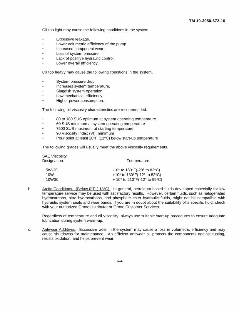
TM 10-3950-672-10
Oil too light may cause the following conditions in the system.
• Excessive leakage.• Lower volumetric efficiency of the pump.• Increased component wear.• Loss of system pressure.• Lack of positive hydraulic control.• Lower overall efficiency.
Oil too heavy may cause the following conditions in the system.
• System pressure drop.• Increases system temperature.• Sluggish system operation.• Low mechanical efficiency.• Higher power consumption.
The following oil viscosity characteristics are recommended.
• 80 to 180 SUS optimum at system operating temperature• 60 SUS minimum at system operating temperature• 7500 SUS maximum at starting temperature• 90 Viscosity Index (VI), minimum• Pour point at least 20°F (11°C) below start-up temperature
The following grades will usually meet the above viscosity requirements.
SAE ViscosityDesignation Temperature
5W-20 -10° to 180°F(-23° to 82°C)10W +10° to 180°F(-12° to 82°C)10W30 + 10° to 210°F(-12° to 99°C)
b. Arctic Conditions. (Below 0°F (-18°C). In general, petroleum-based fluids developed especially for lowtemperature service may be used with satisfactory results. However, certain fluids, such as halogenatedhydrocarbons, nitro hydrocarbons, and phosphate ester hydraulic fluids, might not be compatible withhydraulic system seals and wear bands. If you are in doubt about the suitability of a specific fluid, checkwith your authorized Grove distributor or Grove Customer Services.
Regardless of temperature and oil viscosity, always use suitable start-up procedures to ensure adequatelubrication during system warm-up.
c. Antiwear Additives. Excessive wear in the system may cause a loss in volumetric efficiency and maycause shutdowns for maintenance. An efficient antiwear oil protects the components against rusting,resists oxidation, and helps prevent wear.
6-4
TM 10-3950-672-10
6-1.4 Lubrication Points. A regular frequency of lubrication must be established for all lubrication points.Normally, this is based on component operating time. The most efficient method of keeping track of lube requirements isto maintain a job log indicating crane usage. The log must use the engine hourmeter to ensure coverage of lube pointsthat will receive attention based on their readings. Other lubrication requirements must be made on a time basis, i.e.,weekly, monthly, etc.
All oil levels are to be checked with the crane parked on a level surface in transport position, and whilethe oil is cold, unless otherwise specified.
On plug-type check points, the oil levels are to be at the bottom edge of the check port.
On all hoists with a check plug in the drum, the fill plug shall be directly on top of the hoist, and the checkplug level.
All grease fittings are SAE standard unless otherwise indicated. Grease non- sealed fittings until greaseis seen extruding from the fitting. One ounce (28 grams) of EP-MPG equals one pump on a standard 1.0 lb (0.45 kg)grease gun.
Over lubrication on non-sealed fittings will not harm the fittings or components, but under lubrication willdefinitely lead to a shorter lifetime.
On sealed U-joints, care must be exercised to prevent rupturing seals. Fill only until expansion of theseals first becomes visible.
Unless otherwise indicated, items not equipped with grease fittings, such as linkages, pins, levers, etc.,should be lubricated with oil once a week. Motor oil, applied sparingly, will provide the necessary lubrication and helpprevent the formation of rust. An Anti-Seeze compound may be used if rust has not formed, otherwise the componentmust be cleaned first.
Grease fittings that are worn and will not hold the grease gun, or those that have a stuck check ball, mustbe replaced.
Where wear pads are used, cycle the components and relubricate to ensure complete lubrication of theentire wear area.
6-1.5 Lubrication Chart. The following describe the lubrication points and gives the lube type, lube interval,lube amount, and application of each. Each lubrication point is numbered, and this number corresponds to the indexnumber shown on the Lubrication Chart, Figure 6-1.
Index No. Description/Lube Requirement1 Hook Block Swivel Bearing.
Lube Type - EP-MPGLube Interval - WeeklyLube Amount - Until grease extrudesApplication - 1 grease fitting
6-5
TM 10-3950-672-10
2 Hook Block Sheave.
Lube Type - EP-MPGLube Interval - WeeklyLube Amount - Until grease extrudesApplication - 1 grease fitting
3 Boom Wear Pads.
Lube Type - EP-MPGLube Interval - WeeklyLube Amount - Thoroughly coat the area the wear pad moves onApplication - By brush
4 Boom Nose Sheaves.
Lube Type - EP-MPGLube Interval - WeeklyLube Amount - Until grease extrudesApplication - 1 grease fitting per sheave
5 Telescope Cylinder Wear Pads.
Lube Type - EP-MPGLube Interval - WeeklyLube Amount - Thoroughly coat the area the wear pad moves onApplication - By brush
6 Boom Pivot Shaft.
Lube Type - EP-MPGLube Interval - DailyLube Amount - Until grease extrudesApplication - 2 grease fittings, one on each side of the pivot shaft
7 Lift Cylinder.
NOTE
When greasing the lift cylinder and boom pivot shafts, betterdistribution of grease within the shafts is obtained if the weight of theboom is removed from the shafts.
Lube Type - EP-MPGLube Interval - DailyLube Amount - Until grease extrudesApplication - 2 grease fittings, one on each side of lift cylinder
bushing
6-6

TM 10-3950-672-10
8 Hoist.
Lube Type - EPGL-5HLube Interval - MonthlyLube Amount - Capacity 2.0 qt (1.8 L)Application - With crane level, position the drum so one of the
plugs is directly at the top
9 Engine.
Lube Type - E015W/40Lube Interval - Check daily, drain per Engine Service ManualLube Amount - See Engine Service Manual TM 10-3950-672-24-3Application - See Engine Service Manual TM 10-3950-672-24-3
10 Turntable Bearing.
Lube Type - EP-MPGLube Interval - WeeklyLube Amount - Until grease extrudes the whole circumference on
the bearingApplication - 1 grease fitting. Walk around as the superstructure
is being rotated. Ensure the entire bearing is lubed.
11 Turntable Gear Reducer.
Lube Type - EPGL-5HLube Interval - Weekly, drain 1 st time after 250 hrs and every 500
hrs or 12 months thereafterLube Amount - Capacity - 40 oz (1.18 L)Application - Fill to level on dipstick
12 Turntable Gear and Pinion.
Lube Type - EP-MPGLube Interval - WeeklyLube Amount - Coat all teethApplication - Brush on
13 Tie Rod End and Links.
Lube Type - EP-MPGLube Interval - WeeklyLube Amount - Until grease extrudesApplication - 1 grease fitting on each side of the tie rod, and 1
grease fitting on each spindle
6-7
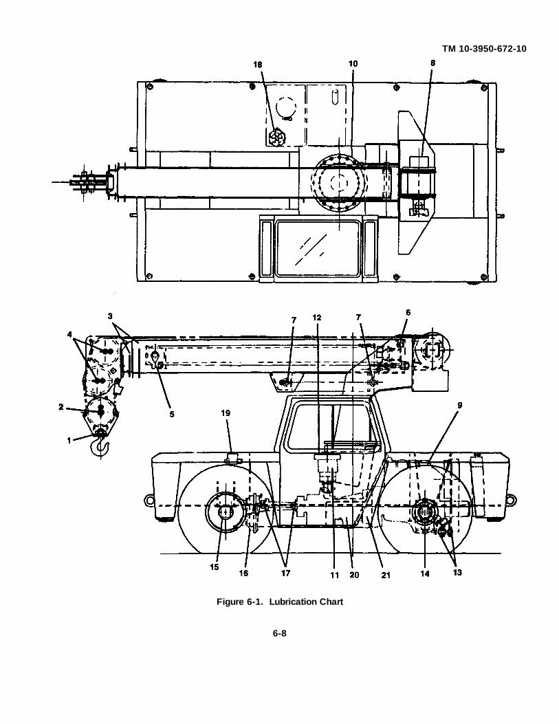
TM 10-3950-672-10
Figure 6-1. Lubrication Chart
6-8

TM 10-3950-672-10
Legend
1. Hook Block Swivel Bearing 11. Turntable Gear Reducer2. Hook Block Sheave 12. Turntable Gear and Pinion3. Boom Wear Pads 13. Tie Rod End and Links4. Boom Nose Sheaves 14. King Pin Bearings5. Telescope Cylinder 15. Wheel Bearings (Drive Axle)6. Boom Pivot Shaft 16. Differential7. Lift Cylinder 17. Drive Line Joints8. Hoist 18. Hydraulic Reservoir9. Engine 19. Master Cylinder
10. Turntable Bearing 20. Transmission (Gearbox)21. Torque Converter
14 King Pins.
Lube Type - EP-MPGLube Interval - WeeklyLube Amount - Until grease extrudesApplication - 1 grease fitting on each side
15 Wheel Bearings (Drive Axle).
Lube Type - EP-MPGLube Interval - Change whenever seals are replaced or when thebrakes are relinedLube Amount - Until fullApplication - Clean and pack the bearings
16 Differential.
Lube Type - EPGL-5Lube Interval - MonthlyLube Amount - 14.0 pt (6.4 L)Application - Fill through the filler hole until lubricant is at bottomof filler hole
17 Drive Line Joints.
Lube Type - EP-MPGbe Interval - Weeklybe Amount - Until grease extrudesApplication - 3 grease fittings
18 Hydraulic Reservoir.
Lube Type - HYDOLube Interval - WeeklyLube Amount - (Total Capacity) 35 gal. (132.4 L)(Gauge Level Capacity) 30 gal. (113.5 L)
6-9

TM 10-3950-672-10
19 Master Cylinder.
Lube Type - SBFLube Interval - WeeklyLube Amount - 6.0 oz (0.18 L)Application - Gain access through the deck cover in front of thecab. Fill to top of reservoir.
20 Transmission.
Lube Type - DEXRON II, or equivalentLube Interval - Check daily with the transmission in N, engine at curb idle rpm, foot
brakes applied, and crane on level surface. Move the transmission selectorlever through D-N-R. Allow time in each range to engage the transmission,return to N, and apply parking brake fully. Do not turn off the engine during thefluid level check. At operating temperature (150° to 170°F [66° to 77°C]), thedipstick reading should have the fluid level on the dipstick is within thecrosshatched area with the engine running at idle. If it should become necessaryto check the fluid at room temperature (70° to 95°F [21° to 35°C]), the dipstickreading should have the fluid level on the dipstick between the two holespunched in the dipstick.
NOTE
For more information on fluid level checks and fluidconditions, refer to TM 10-3950-672-24-2.
Lube Amount - If a partial drain was done, add 5 qt (4.7 L)shallow pan or 6 qt (5.6 L) deep pan of fluid through thefiller tube. Check the fluid. If a complete drain was done,the approximate refill capacity is 11.75 qt (11.2 L). Theapproximate dry capacity includes cooler and lines.
Application - Through the filler tube
6-1.6 Wire Rope Lubrication. Wire rope is lubricated during manufacturing so the strands, and individualwires in strands, may move and adjust as the rope moves and bends. A wire rope cannot be lubricated sufficiently duringmanufacture to last its entire life. Therefore, new lubricant must be added periodically throughout the life of a rope toreplace factory lubricant which is used or lost.
The surface of some ropes may become covered with dirt, rock dust, or other material during theiroperation. This covering can prevent field applied lubricants from properly penetrating into the rope. Therefore, theseropes should be cleaned before being lubricated.
6-10

TM 10-3950-672-10
The lubricant applied should be light-bodied enough to penetrate to the core of the rope. Lubricant maybe applied effectively by various methods. It may be dripped on, sprayed on, or put on by brushing, but in any case itshould be applied at a place where the rope is being bent, such as at a sheave. It should be applied at the top of thebend, because at this point the strands are spread by bending and are more easily penetrated. The service life of ropewill be directly proportional to the effectiveness of the method used and amount of lubricant reaching the working parts ofthe rope.
A proper lubricant must reduce friction, protect against corrosion, adhere to every wire and be pliable andnot crack or separate when cold and yet not drip when warm.
Special lubricant can be applied at the factory to meet unusual conditions.
Figure 6-2. Wire Rope Lubrication
6-11

TM 10-3950-672-10
6-2. TROUBLESHOOTING.
SYMPTOM INDEX
Malfunction TroubleshootingProcedures
Page
ENGINE
Engine will not crank or cranks slowly ............................ ..................................................... 6-13Engine hard to start or will not start - exhaust smoke present ............................................. 6-14Engine cranks, but will not start - no smoke from exhaust ................................................... 6-14Engine starts but will not keep running ................................................................................ 6-15Engine will not shut off ........................................................................................................ 6-15Rough idle, warm engine .................................................................................................... 6-15Engine surges at idle ........................................ .................................................................. 6-16Low lubricating oil pressure ................................................................................................. 6-16Lubricating oil pressure too high ................................ ......................................................... 6-16Lube oil loss ...................................................... ................................................................. 6-17Contaminated engine oil ...................................... ............................................................... 6-17Exhaust smoke excessive under load ............................. .................................................... 6-17Engine will not reach rated speed when loaded ................................................................... 6-17Low power ............................................... ........................................................................... 6-18Engine misfiring .................................................................................................................. 6-18Fuel knock ......................................................................................................................... 6-18Excessive fuel consumption ................................... ........................................................... 6-19Excessive vibration ............................................................................................................ 6-19Excessive engine noises ..................................................................................................... 6-19Fuel or oil leaking from exhaust manifold .......................... ................................................. 6-20
COOLING SYSTEM
Coolant temperature above normal ..................................................................................... 6-20Coolant loss ........................................................................................................................ 6-21Coolant temperature below normal ............................... ...................................................... 6-21Contaminated coolant ........................................................................................................ 6-22
ELECTRICAL SYSTEM
Alternator not charging or insufficient charging ................................................................... 6-22
TRANSMISSION
Crane will not move or moves erratically (transmission failure) ........................................... 6-23Transmission oil temperature above normal ....................................................................... 6-23
BRAKES
Brakes are poor or do not apply .......................................................................................... 6-23
6-12
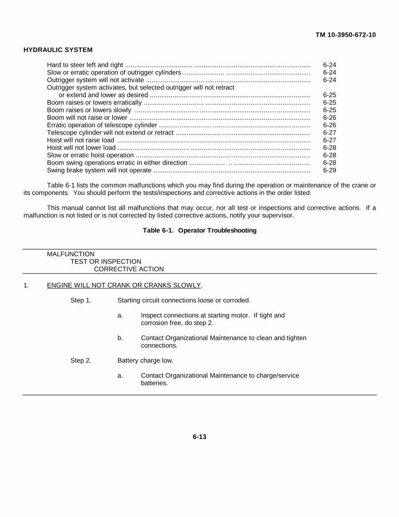
TM 10-3950-672-10
HYDRAULIC SYSTEM
Hard to steer left and right .................................... .............................................................. 6-24Slow or erratic operation of outrigger cylinders ...................... ............................................. 6-24Outrigger system will not activate ............................... ........................................................ 6-24Outrigger system activates, but selected outrigger will not retract
or extend and lower as desired ............................ ......................................................... 6-25Boom raises or lowers erratically ................................ ........................................................ 6-25Boom raises or lowers slowly .................................. ........................................................... 6-25Boom will not raise or lower ................................... ............................................................. 6-26Erratic operation of telescope cylinder ............................ .................................................... 6-26Telescope cylinder will not extend or retract ........................ ............................................... 6-27Hoist will not raise load ...................................... ................................................................ 6-27Hoist will not lower load ...................................... ................................................................ 6-28Slow or erratic hoist operation ............................................................................................. 6-28Boom swing operations erratic in either direction ................... .. ......................................... 6-28Swing brake system will not operate ............................. ...................................................... 6-29
Table 6-1 lists the common malfunctions which you may find during the operation or maintenance of the crane orits components. You should perform the tests/inspections and corrective actions in the order listed.
This manual cannot list all malfunctions that may occur, nor all test or inspections and corrective actions. If amalfunction is not listed or is not corrected by listed corrective actions, notify your supervisor.
Table 6-1. Operator Troubleshooting
MALFUNCTIONTEST OR INSPECTION
CORRECTIVE ACTION
1. ENGINE WILL NOT CRANK OR CRANKS SLOWLY.
Step 1. Starting circuit connections loose or corroded.
a. Inspect connections at starting motor. If tight andcorrosion free, do step 2.
b. Contact Organizational Maintenance to clean and tightenconnections.
Step 2. Battery charge low.
a. Contact Organizational Maintenance to charge/servicebatteries.
6-13
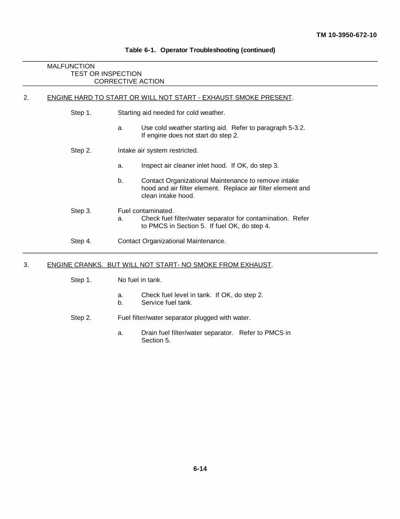
TM 10-3950-672-10
Table 6-1. Operator Troubleshooting (continued)
MALFUNCTIONTEST OR INSPECTION
CORRECTIVE ACTION
2. ENGINE HARD TO START OR WILL NOT START - EXHAUST SMOKE PRESENT.
Step 1. Starting aid needed for cold weather.
a. Use cold weather starting aid. Refer to paragraph 5-3.2.If engine does not start do step 2.
Step 2. Intake air system restricted.
a. Inspect air cleaner inlet hood. If OK, do step 3.
b. Contact Organizational Maintenance to remove intakehood and air filter element. Replace air filter element andclean intake hood.
Step 3. Fuel contaminated.a. Check fuel filter/water separator for contamination. Refer
to PMCS in Section 5. If fuel OK, do step 4.
Step 4. Contact Organizational Maintenance.
3. ENGINE CRANKS. BUT WILL NOT START- NO SMOKE FROM EXHAUST.
Step 1. No fuel in tank.
a. Check fuel level in tank. If OK, do step 2.b. Service fuel tank.
Step 2. Fuel filter/water separator plugged with water.
a. Drain fuel filter/water separator. Refer to PMCS inSection 5.
6-14

TM 10-3950-672-10
Table 6-1. Operator Troubleshooting (continued)
MALFUNCTIONTEST OR INSPECTION
CORRECTIVE ACTION
4. ENGINE STARTS BUT WILL NOT KEEP RUNNING.
Step 1. Fuel waxing due to cold weather.
a. Drain fuel filter/water separator. Refer to PMCS inSection 5. If OK, do step 2.
b. Contact Organizational Maintenance to drain fuel tank andservice with cold weather fuel grade.
Step 2. Fuel contaminated.
a. Check fuel/filter water separator for contamination. Referto PMCS in Section 5. If fuel Ok, do step 3.
Step 3. Contact Organizational Maintenance.
5. ENGINE WILL NOT SHUT OFF.
Step 1. Fuel system malfunction.
a. Set outriggers and shut down diesel engine. Shut off fuelsupply shutoff valve at fuel tank. Refer to shutdownprocedures, paragraph 5-3.3.
b. Contact Organizational Maintenance.
6. ROUGH IDLE. WARM ENGINE.Step 1. Intake air system restricted.
a. Inspect air cleaner inlet hood. If OK, do step 2.
b. Contact Organizational Maintenance to remove intakehood and air filter element. Replace air filter element andclean intake hood.
Step 2. Fuel contaminated.
a. Check fuel filter/water separator for contamination. Referto PMCS in Section 5. If fuel OK, do step 3.
Step 3. Contact Organizational Maintenance.
6-15
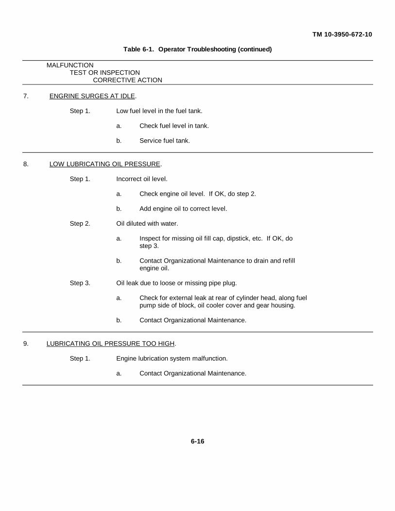
TM 10-3950-672-10
Table 6-1. Operator Troubleshooting (continued)
MALFUNCTIONTEST OR INSPECTION
CORRECTIVE ACTION
7. ENGRINE SURGES AT IDLE.
Step 1. Low fuel level in the fuel tank.
a. Check fuel level in tank.
b. Service fuel tank.
8. LOW LUBRICATING OIL PRESSURE.
Step 1. Incorrect oil level.
a. Check engine oil level. If OK, do step 2.
b. Add engine oil to correct level.
Step 2. Oil diluted with water.
a. Inspect for missing oil fill cap, dipstick, etc. If OK, dostep 3.
b. Contact Organizational Maintenance to drain and refillengine oil.
Step 3. Oil leak due to loose or missing pipe plug.
a. Check for external leak at rear of cylinder head, along fuelpump side of block, oil cooler cover and gear housing.
b. Contact Organizational Maintenance.
9. LUBRICATING OIL PRESSURE TOO HIGH.
Step 1. Engine lubrication system malfunction.
a. Contact Organizational Maintenance.
6-16

TM 10-3950-672-10
Table 6-1. Operator Troubleshooting (continued)
MALFUNCTIONTEST OR INSPECTION
CORRECTIVE ACTION
10. LUBE OIL LOSS.
Step 1. External leaks.
a. Visually inspect for oil leaks. If no leaks, do step 2.
b. Contact Organizational Maintenance.
Step 2. Crankcase overfilled.
a. Remove dipstick and check oil level. If OK, do step 3.
b. Contact Organizational Maintenance to drain engine oil toproper level.
Step 3. Engine lubrication system malfunction.
a. Contact Organizational Maintenance.
11. CONTAMINATED ENGINE OIL.
Step 1. Engine lubrication system malfunction.
a. Contact Organizational Maintenance.
12. EXHAUST SMOKE EXCESSIVE UNDER LOAD.
Step 1. Engine overloaded.
a. Downshift to lower gear.
Step 2. Fuel system malfunction.
a. Contact Organizational Maintenance.
13. ENGINE WILL NOT REACH RATED SPEED WHEN LOADED.
Step 1. Vehicle overloaded.
a. Reduce load or downshift to lower gear.
6-17

TM 10-3950-672-10
Table 6-1. Operator Troubleshooting (continued)
MALFUNCTIONTEST OR INSPECTION
CORRECTIVE ACTION
Step 2. Fuel system malfunction.
a. Contact Organizational Maintenance.
14. LOW POWER.
Step 1. Vehicle overloaded.
a. Reduce load or downshift to lower gear.
Step 2. Engine oil level too high.
a. Remove dipstick and check engine oil level. If OK, dostep 3.
b. Contact Organizational Maintenance to drain engine oil toproper level.
Step 3. Fuel system malfunction.
a. Contact Organizational Maintenance.
15. ENGINE MISFIRING.
Step 1. Fuel system malfunction.
a. Contact Organizational Maintenance.
16. FUEL KNOCK.
Step 1. Engine overloaded.
a. Downshift to lower gear.
Step 2. Fuel system malfunction.
a. Contact Organizational Maintenance.
6-18

TM 10-3950-672-10
Table 6-1. Operator Troubleshooting (continued)
MALFUNCTIONTEST OR INSPECTION
CORRECTIVE ACTION
17. EXCESSIVF FUEL CONSUMPTION.
Step 1. Operator Technique.
a. Review Section 5 - Operating Instructions. If OK, do step2.
Step 2. Fuel leak.
a. Inspect for fuel leaks. If OK, do step 3.
b. Contact Organizational Maintenance to repair leaks.
Step 3. Fuel system malfunction.
a. Contact Organizational Maintenance.
18. EXCESSIVE VIBRATION.
Step 1. Engine drive component failure.
a. Contact Organizational Maintenance.
19. EXCESSIVE ENGINE NOISES.
Step 1. Drive belt squeal, insufficient tension or abnormally high loading.
a. Check belt tension and condition of drive belt. Refer toPMCS in Section 5.
b. Contact Organizational Maintenance to replace drive beltor tensioner.
Step 2. Defective engine.
a. Contact Organizational Maintenance.
6-19
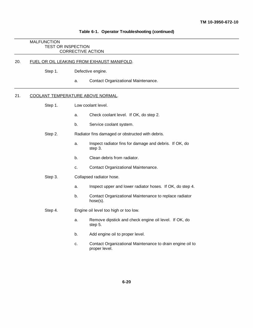
TM 10-3950-672-10
Table 6-1. Operator Troubleshooting (continued)
MALFUNCTIONTEST OR INSPECTION
CORRECTIVE ACTION
20. FUEL OR OIL LEAKING FROM EXHAUST MANIFOLD.
Step 1. Defective engine.
a. Contact Organizational Maintenance.
21. COOLANT TEMPERATURE ABOVE NORMAL.
Step 1. Low coolant level.
a. Check coolant level. If OK, do step 2.
b. Service coolant system.
Step 2. Radiator fins damaged or obstructed with debris.
a. Inspect radiator fins for damage and debris. If OK, dostep 3.
b. Clean debris from radiator.
c. Contact Organizational Maintenance.
Step 3. Collapsed radiator hose.
a. Inspect upper and lower radiator hoses. If OK, do step 4.
b. Contact Organizational Maintenance to replace radiatorhose(s).
Step 4. Engine oil level too high or too low.
a. Remove dipstick and check engine oil level. If OK, dostep 5.
b. Add engine oil to proper level.
c. Contact Organizational Maintenance to drain engine oil toproper level.
6-20

TM 10-3950-672-10
Table 6-1. Operator Troubleshooting (continued)
MALFUNCTIONTEST OR INSPECTION
CORRECTIVE ACTION
Step 5. Loose fan drive belt.
a. Inspect fan drive belt and belt tensioner. Refer to PMCSin Section 5. If OK, do step 6.
b. Contact Organizational Maintenance to replace fan drivebelt and/or tensioner.
Step 6. Engine overloaded.
a. Reduce load and downshift to lower gear.
Step 7. Defective engine.
a. Contact Organizational Maintenance.
22. COOLANT LOSS.
Step 1. Radiator leaking coolant.
a. Visually inspect radiator hoses and connections to locateleak. If OK, do step 2.
b. Contact Organizational Maintenance to replace radiatorcomponents.
Step 2. External engine leaks.
a. Visually inspect engine and components for seal or gasketleaks.
b. Contact Organizational Maintenance to repair leaks.
23. COOLANT TEMPERATURE BELOW NORMAL.
Step 1. Temperature sensor or gauge malfunction.
a. Contact Organizational Maintenance.
6-21

TM 10-3950-672-10
Table 6-1. Operator Troubleshooting (continued)
MALFUNCTIONTEST OR INSPECTION
CORRECTIVE ACTION
24. CONTAMINATED COOLANT.
Step 1. Coolant system malfunction.
a. Contact Organizational Maintenance to repair coolantsystem.
25. ALTERNATOR NOT CHARGING OR INSUFFICIENT CHARGING.
Step 1. Loose or corroded battery connections.
a. Inspect battery connection. If OK, do step 2.
b. Contact Organizational Maintenance to clean or tightenbattery connections.
Step 2. Fan drive belt slipping.
a. Inspect fan drive belt tensioner by hand. Refer to PMCSin Section 5. If OK, do step 3.
b. Contact Organizational Maintenance to replace fan drivebelt and/or tensioner.
Step 3. Alternator pulley loose on shaft.
a. Inspect alternator pulley. If OK, do step 4.
b. Contact Organizational Maintenance to tighten alternatorpulley.
Step 4. Charging system malfunction.
a. Contact Organizational Maintenance.
6-22

TM 10-3950-672-10
Table 6-1. Operator Troubleshooting (continued)
MALFUNCTIONTEST OR INSPECTION
CORRECTIVE ACTION
26. CRANE WILL NOT MOVE OR MOVES ERRATICALLY (TRANSMISSION FAILURE).
Step 1. Low transmission oil level.
a. Remove dipstick and check transmission oil level. If OK,do step 2. Refer to PMCS in Section 5.
b. Fill to proper level.
Step 2. Transmission shift lever at N-Neutral.
a. Check position of transmission shift lever.
Step 3. Defective transmission.
a. Contact Organizational Maintenance.
27. TRANSMISSION OIL TEMPERATURE ABOVE NORMAL.
Step 1. Low transmission oil level.
a. Remove dipstick and check oil level. Refer to PMCS inSection 5. If OK, do step 2.
b. Fill to proper level.
Step 2. Defective transmission.
a. Contact Organizational Maintenance.
28. BRAKES ARE POOR OR DO NOT APPLY.
Step 1. Low master brake cylinder fluid level.
a. Check brake fluid level in master cylinder. Refer to PMCSin Section 5. If OK, Contact Organizational Maintenance.
b. Service master brake cylinder.
6-23

TM 10-3950-672-10
Table 6-1. Operator Troubleshooting (continued)
MALFUNCTIONTEST OR INSPECTION
CORRECTIVE ACTION
29. HARD TO STEER LEFT AND RIGHT.
Step 1. Hydraulic oil low.
a. Check hydraulic oil level in reservoir. Refer to PMCS inSection 5. If OK, do step 2.
b. Service hydraulic reservoir.
Step 2. Steering system failure.
a. Contact Organizational Maintenance.
30. SLOW OR ERRATIC OPERATION OF OUTRIGGER CYLINDERS.
Step 1. Low hydraulic oil.
a. Check hydraulic oil level. Refer to PMCS in Section 5. IfOK, do step 2.
b. Service hydraulic reservoir.
Step 2. Outrigger system malfunction.
a. Contact Organizational Maintenance.
31. OUTRIGGER SYSTEM WILL NOT ACTIVATE.
Step 1. Hydraulic oil low.
a. Check hydraulic oil level. Refer to PMCS in Section 5. IfOK, do step 2.
b. Service hydraulic reservoir.
Step 2. Outrigger system malfunction.
a. Contact Organizational Maintenance.
6-24
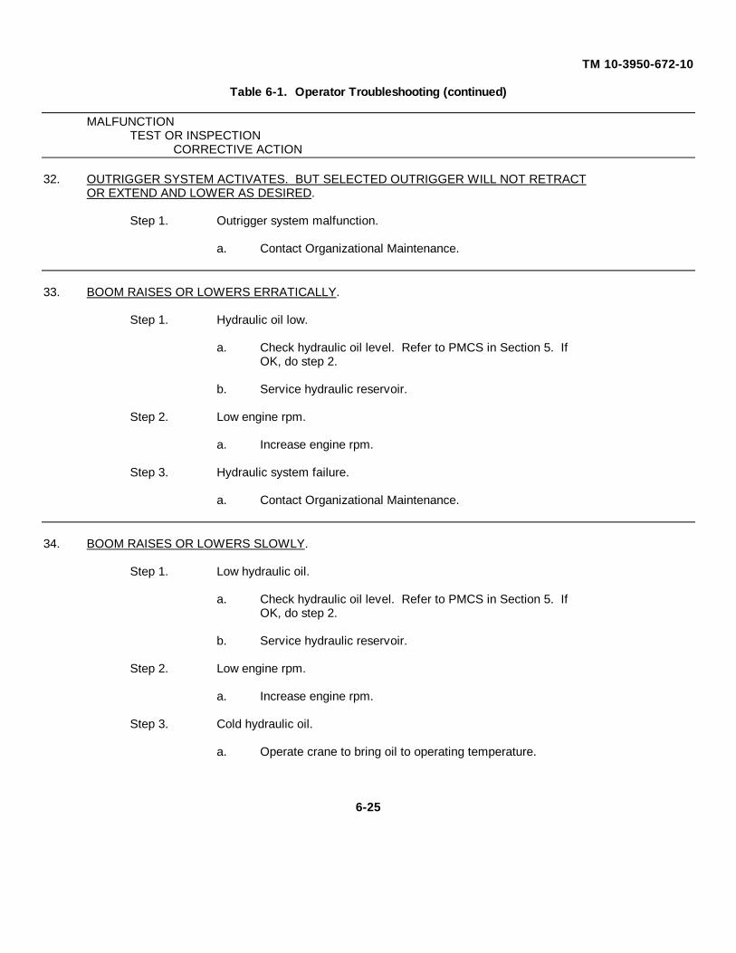
TM 10-3950-672-10
Table 6-1. Operator Troubleshooting (continued)
MALFUNCTIONTEST OR INSPECTION
CORRECTIVE ACTION
32. OUTRIGGER SYSTEM ACTIVATES. BUT SELECTED OUTRIGGER WILL NOT RETRACTOR EXTEND AND LOWER AS DESIRED.
Step 1. Outrigger system malfunction.
a. Contact Organizational Maintenance.
33. BOOM RAISES OR LOWERS ERRATICALLY.
Step 1. Hydraulic oil low.
a. Check hydraulic oil level. Refer to PMCS in Section 5. IfOK, do step 2.
b. Service hydraulic reservoir.
Step 2. Low engine rpm.
a. Increase engine rpm.
Step 3. Hydraulic system failure.
a. Contact Organizational Maintenance.
34. BOOM RAISES OR LOWERS SLOWLY.
Step 1. Low hydraulic oil.
a. Check hydraulic oil level. Refer to PMCS in Section 5. IfOK, do step 2.
b. Service hydraulic reservoir.
Step 2. Low engine rpm.
a. Increase engine rpm.
Step 3. Cold hydraulic oil.
a. Operate crane to bring oil to operating temperature.
6-25

TM 10-3950-672-10
Table 6-1. Operator Troubleshooting (continued)
MALFUNCTIONTEST OR INSPECTION
CORRECTIVE ACTION
Step 4. Hydraulic system failure.
a. Contact Organizational Maintenance.
35. BOOM WILL NOT RAISE OR LOWER.
Step 1. Low hydraulic oil.
a. Check hydraulic oil level. Refer to PMCS in Section 5. IfOK, do step 2.
b. Service hydraulic reservoir.
Step 2. Excessive load.
a. Reduce load as required.
Step 3. Hydraulic system failure.
a. Contact Organizational Maintenance.
36. ERRATIC OPERATION OF TELESCOPE CYLINDER.
Step 1. Low hydraulic oil.
a. Check hydraulic oil level. Refer to PMCS in Section 5. IfOK, do step 2.
b. Service hydraulic reservoir.
Step 2. Low engine rpm.
a. Increase engine rpm.
Step 3. Lack of lubrication on boom section.
a. Lubricate boom sections. Refer to paragraph 6-1.5.
Step 4. Side loading causing improper boom alignment.
a. Reduce load. Use proper hoisting procedures.
6-26

TM 10-3950-672-10
Table 6-1. Operator Troubleshooting (continued)
MALFUNCTIONTEST OR INSPECTION
CORRECTIVE ACTION
Step 5. Hydraulic system failure.
a. Contact Organizational Maintenance.
37. TELESCOPE CYLINDER WILL NOT EXTEND OR RETRACT.
Step 1. Low hydraulic oil level.
a. Check hydraulic oil level. Refer to PMCS in Section 5. IfOK, do step 2.
b. Service hydraulic reservoir.
Step 2. Excessive load.
a. Reduce load.
Step 3. Hydraulic system failure.
a. Contact Organizational Maintenance.
38. HOIST WILL NOT RAISE LOAD.
Step 1. Load capacity exceeded.
a. Reduce load.
Step 2. Low hydraulic oil.
a. Check hydraulic oil level. Refer to PMCS in Section 5. IfOK, do step 3.
b. Service hydraulic reservoir.
Step 3. Hydraulic system failure.
a. Contact Organizational Maintenance.
6-27

TM 10-3950-672-10
Table 6-1. Operator Troubleshooting (continued)
MALFUNCTIONTEST OR INSPECTION
CORRECTIVE ACTION
39. HOIST WILL NOT LOWER LOAD.
Step 1. Malfunctioning hoist brake.
a. Contact Organizational Maintenance.
40. SLOW OR ERRATIC HOIST OPERATION.
Step 1. Low engine rpm.
a. Increase rpm.
Step 2. Hydraulic system failure.
a. Contact Organizational Maintenance.
41. BOOM SWING OPERATIONS ERRATIC IN EITHER DIRECTION.
Step 1. Low engine rpm.
a. Increase rpm.
Step 2. Low hydraulic oil.
a. Check hydraulic oil level. Refer to PMCS in Section 5. IfOK, do step 3.
b. Service hydraulic reservoir.
Step 3. Insufficient lubricant on swing bearing.
a. Inspect swing bearing. Lubricate bearing. Refer toparagraph 6-1.5.
Step 4. Crane not level.
a. Level crane using outriggers.
Step 5. Crane overloaded.
a. Reduce load.
6-28

TM 10-3950-672-10
Table 6-1. Operator Troubleshooting (continued)
MALFUNCTIONTEST OR INSPECTION
CORRECTIVE ACTION
Step 6. Swing system failure.
a. Contact Organizational Maintenance.
42. SWING BRAKE SYSTEM WILL NOT OPERATE.
Step 1. Low hydraulic oil.
a. Check hydraulic oil level. Refer to PMCS in Section 5. IfOK, do step 2.
b. Service hydraulic reservoir.
Step 2. Swing system failure.
a. Contact Organizational Maintenance.
6-3. INSTALLING CABLE ON THF HOIST.
WARNING
Wear heavy gloves and safety glasses when workingwith the hoist cable. Failure to follow this warning couldresult in personal injury.
CAUTION
If cable is wound from the storage reel onto the drum,the reel should be rotated in the same direction as thehoist.
NOTE
The cable should preferably be straightened beforeinstallation on the hoist drum.
Install cable on the hoist drum using Figure 6-3 and the following procedures.
a. Position the cable over the boom nose sheave and route to the hoist drum.
6-29

TM 10-3950-672-10
b. Position the hoist drum with the cable anchor slot on top, (Figure 6-3).
c. Insert the cable through the slot and position around the anchor wedge.
NOTE
The end of the cable should be even with the bottom of theanchor wedge.
d. Position the anchor wedge in the drum slot; pull firmly on the free end of thecable to secure the wedge.
NOTE
If the wedge does not seat securely in the slot, carefullytap the top of the wedge with a mallet.
e. Slowly rotate the drum, ensuring the first layer of cable is evenly wound ontothe drum.
f. Install the remainder of the cable, as applicable.
Figure 6-3. Installing Cable Anchor Wedge
6-4. CABLE REEVING.
Within the limits of the load and range charts and permissible line pull, multi-part lines allow the operator to raisea greater load then can be raised with a single part line. This reeving should be accomplished by a qualified rigger usingstandard rigging procedures.
6-30

TM 10-3950-672-10
Figure 6-4 illustrates cable reeving for the AP308T which includes routing the cable over the upper boom nosesheave (1), lower boom nose sheave (2), hook block sheave (3), and lower boom nose sheave (4) with the cableterminating at the wedge socket (5).
LEGEND
1. Upper BoomNose Sheave
2. Lower BoomNose Sheave No. 1
3. Hook BlockSheave
4. Lower BoomNose Sheave No. 2
5. Wedge Socket
Figure 6-4. Boom Nose and Hook Block Cable Reeving
6-5. INSTALLING WEDGE AND SOCKET.
WARNING
Use only a wedge and socket of the correct size for thewire rope (cable) fitted. Failure to do so may result inthe rope pulling through the fitting.
Make sure the live-loaded side of the cable is in line withthe ears of the socket as shown in Figure 6-5. If thewire rope is loaded incorrectly, it will bend under a loadas it leaves the socket. The edge of the socket willeventually wear into the rope causing damage andfailure.
6-31

TM 10-3950-672-10
a. Inspect the wedge and socket. Remove rough edges and burrs.
b. If the wire rope is welded, cut the welded end off. This will allow distortion in the rope strands to adjustthemselves at the end of the line.
c. Insert wire rope into socket as shown in Figure 6-5 pulling the end through until it extends from thesocket a distance of approximately nine times the rope diameter [a minimum of six inches (15.2 cm)].
d. Place wedge in socket.
e. Place a wire rope clip around the dead end by clamping a short piece of extra wire rope to the dead end.DO NOT CLAMP THE LIVE END. The u-bolt should bear against the dead end with the saddle of theclip resting against the short extra piece. Torque the u-bolts as follows:
Clip Size Torque Clip Size Torque(Inches) (Ib-ft, dry) (Inches) (Ib-ft, dry)
1/8 3 5/8 75
3/16 4.5 3/4 75
1/4 15 7/8 130
5/16 15 1 130
3/8 30 1-1/8 200
7/16 40 1-1/4 200
1/2 45 1-3/8 360
9/16 50 1-1/2 360
f. Secure ears of socket to a sturdy support. Pull wedge and rope into position with tension on the live sideof the wire rope sufficiently tight enough to hold them in place.
g. After final pin connections are made, increase loads gradually until wedge is properly seated.
Figure -65. Dead-End Rigging/Wedge Socket
6-32

TM 10-3950-672-10
APPENDIX A
REFERENCES
A-1 SCOPE
This appendix lists all forms and publications that are referenced in this manual.
A-2 PAMPHLETS
DA Pam 25-30 Consolidated Index of Army Publications and Blank Forms
DA Pam 738-750 The Army Maintenance Management System (TAMMS)
A-3 FORMS
DA Form 2404 Equipment Inspection and Maintenance Worksheet
DA Form 2028 Recommended Changes to Publications and Blank Forms
DA Form 2028-2 Recommended Changes to Equipment TechnicalPublications
SF 361 Transportation Discrepancy Report
SF 364 Report of Discrepancy (ROD)
SF 368 Product Quality Deficiency Report
A-4 SUPPLY BULLETINS
A-5 TECHNICAL BULLETINS
A-6 TECHNICAL MANUALS
TM 43-0139 Painting Instructions for Field Use
A-7 FIELD MANUALS
FM 21-11 First Aid for Soldiers
A-8 MISCELLANEOUS PUBLICATIONS
CTA 50-970 Expendable Items (Except: Medical, Class V, Repair Partsand Heraldic Items)
A-1/(A-2 blank)

TM 10-3950-672-10
APPENDIX B
COMPONENTS OF END ITEM AND BASIC ISSUE ITEMS LISTS
Section I. INTRODUCTION
B-1. SCOPE
This appendix lists components of end item and basic issue items for the 10K Warehouse Crane, M469 to help youinventory items required for safe and efficient operation.
B-2. GENERAL
The components of end item and basic issue items lists are divided into the following sections.
a. Section II. Components of End Item
This listing is for informational purposes only, and is not authority to requisition replacements. These itemsare part of the end item, but are removed and separately packaged for transportation and shipment. As partof the end item, these items must be with the end item whenever it is issued or transferred between propertyaccounts. Illustrations are furnished to assist you in identifying the items.
b. Section III. Basic Issue Items
These are the minimum essential items required to place the 1 OK Warehouse Crane in operation, tooperate it, and perform emergency repairs. Although shipped separately, packaged Bll must be with thecrane during operation and whenever it is transferred between property accounts. The illustrations will assistyou with hard to identify items. This manual is your authority to request/requisition replacement Bll, based onTOE/MTOE authorization of the end item.
B-3. EXPLANATION OF COLUMNS
The following provides an explanation of columns found in the tabular listings.
a. Column (1) Illustration Number (Illus No.)
This column indicates the number of the illustration in which the item is shown.
b. Column (2) National Stock Number
Indicates the national stock number assigned to the item and will be used for requisitioning purposes.
B-1

TM 10-3950-672-10
B-3. EXPLANATION OF COLUMNS - Continued
c. Column (3) - Description (Description (CAGEC) and Part Number)
Indicates the national item name and, if required, a minimum description to identify and locate the item. Thelast line for each item indicates the Commercial and Government Entity (CAGE) Code (in parentheses)followed by the part number.
d. Column (4) Unit of Measure (U/M)
Indicates the measure used in performing the actual operational/maintenance function. This measure isexpressed by a two-character alphabetical abbreviation (e.g., EA, IN, PR).
e. Column (5) Quantity Required (Qty Reqd)
Indicates the quantity of the item authorized to be used with/on the equipment.
B-2

TM 10-3950-672-10
Section II. COMPONENTS OF END ITEM - 10K Warehouse Crane, M 469
(1) (2) (3) (4) (5)National
Illus. Stock Description Usable QtyNo. Number (CAGEC) and Part Number On Code U/M Reqd
1 3950-01-412-5345 Warehouse Crane, 10K DED, RWV EA 1M 469(12361) SK 950336
B-3
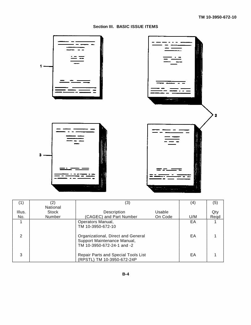
TM 10-3950-672-10
Section III. BASIC ISSUE ITEMS
(1) (2) (3) (4) (5)National
Illus. Stock Description Usable QtyNo. Number (CAGEC) and Part Number On Code U/M Reqd1 Operators Manual, EA 1
TM 10-3950-672-10
2 Organizational, Direct and General EA 1Support Maintenance Manual,TM 10-3950-672-24-1 and -2
3 Repair Parts and Special Tools List EA 1(RPSTL) TM 10-3950-672-24P
B-4

TM 10-3950-672-10
APPENDIX C
ADDITIONAL AUTHORIZATION LIST
Section I. INTRODUCTION
C-1. SCOPE
This appendix lists additional items your are authorized for the support of the 10K Warehouse Crane, M469.
C-2. GENERAL
The list identifies items that do not have to accompany the crane and that do not have to be turned in with it.These items are all authorized to you by CTA, MTOE, TDA, or JTA.
C-3. EXPLANATION OF LISTING
The following provides an explanation of columns found in the tabular listings.
a. Column ( 1 ) National Stock Number
Indicates the national stock number assigned to the item and will be used for requisitioning purposes.
b. Column (2) Description (Description (CAGE) and Part Number)
Indicates the national item name and, if required, a minimum description to identify and locate the item. Thelast line for each item indicates the Commercial and Government Entity (CAGE) Code (in parentheses)followed by the part number.
c. Column (3) Unit of Measure (U/M)
Indicates the measure used in performing the actual operational/maintenance function. This measure isexpressed by a two-character alphabetical abbreviation (e.g., EA, IN, PR).
d. Column (4) Quantity Required (Qty Reqd)
Indicates the quantity of the item authorized to be used with/on the equipment.
C-1

TM 10-3950-672-10
Section II. ADDITIONAL AUTHORIZATION LIST - 10K Warehouse Crane, M 469
(1) (2) (3) (4)NationalStock Description Usable Qty
Number (CAGEC) and Part Number On Code U/M Reqd
MTOE AUTHORIZED ITEMS
7520-00-559-9618 Bag, Pamphlet RWV EA 14240-00-052-3776 Goggles, Eye Protection RWV PR 28415-00-889-3767 Helmet, Construction RWV EA 26545-00-912-1200 Kit, First Aid RWV EA 1
CTA AUTHORIZED ITEMS
NONE
C-2

TM 10-3950-672-10
APPENDIX E
LOAD CHART
E-1. SCOPE
This appendix contains the load chart for the 10 K Warehouse Crane, M469.
E-1

TM 10-3950-672-10
Figure E-1. Load Chart, 10K Warehouse Crane (Sheet 1 of 9).
E-2

TM 10-3950-672-10
Figure E-1. Load Chart, 10K Warehouse Crane (Sheet 2 of 9 ).
E-3
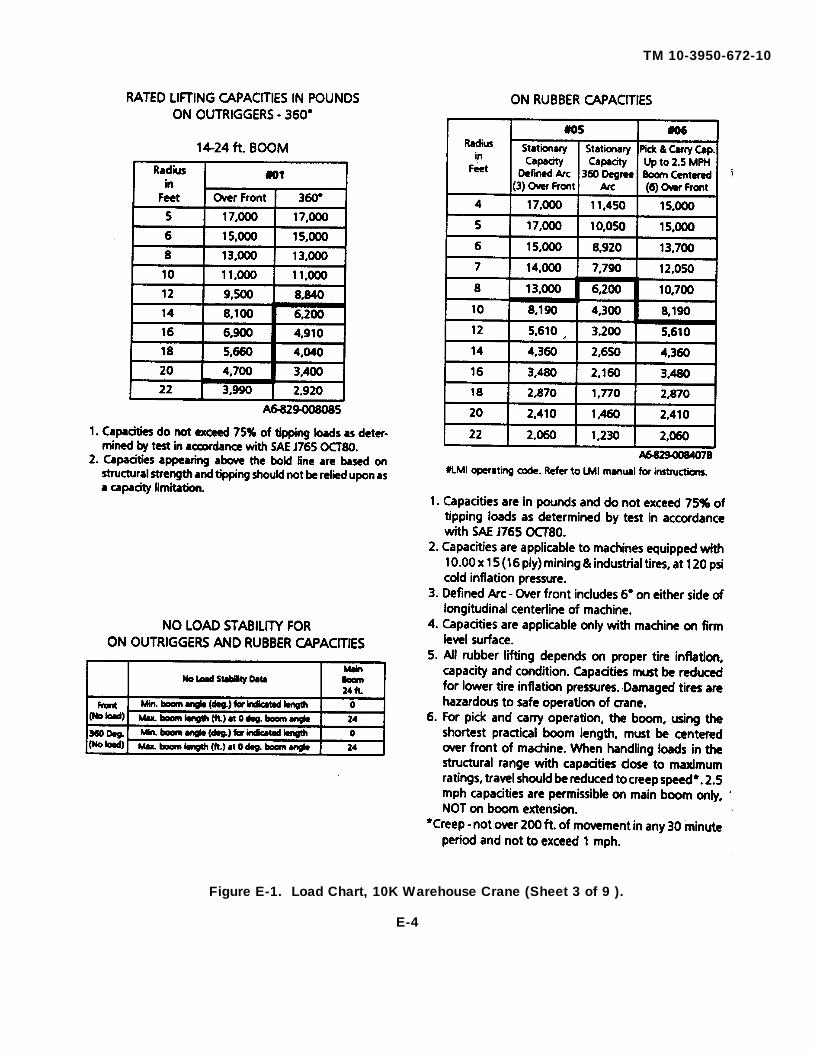
TM 10-3950-672-10
Figure E-1. Load Chart, 10K Warehouse Crane (Sheet 3 of 9 ).
E-4

TM 10-3950-672-10
Figure E-1. Load Chart, 10K Warehouse Crane (Sheet 4 of 9 ).
E-5

TM 10-3950-672-10
Figure E-1. Load Chart, 10K Warehouse Crane (Sheet 5 of 9 ).
E-6

TM 10-3950-672-10
Figure E-1. Load Chart, 10K Warehouse Crane (Sheet 6 of 9 ).
E-7
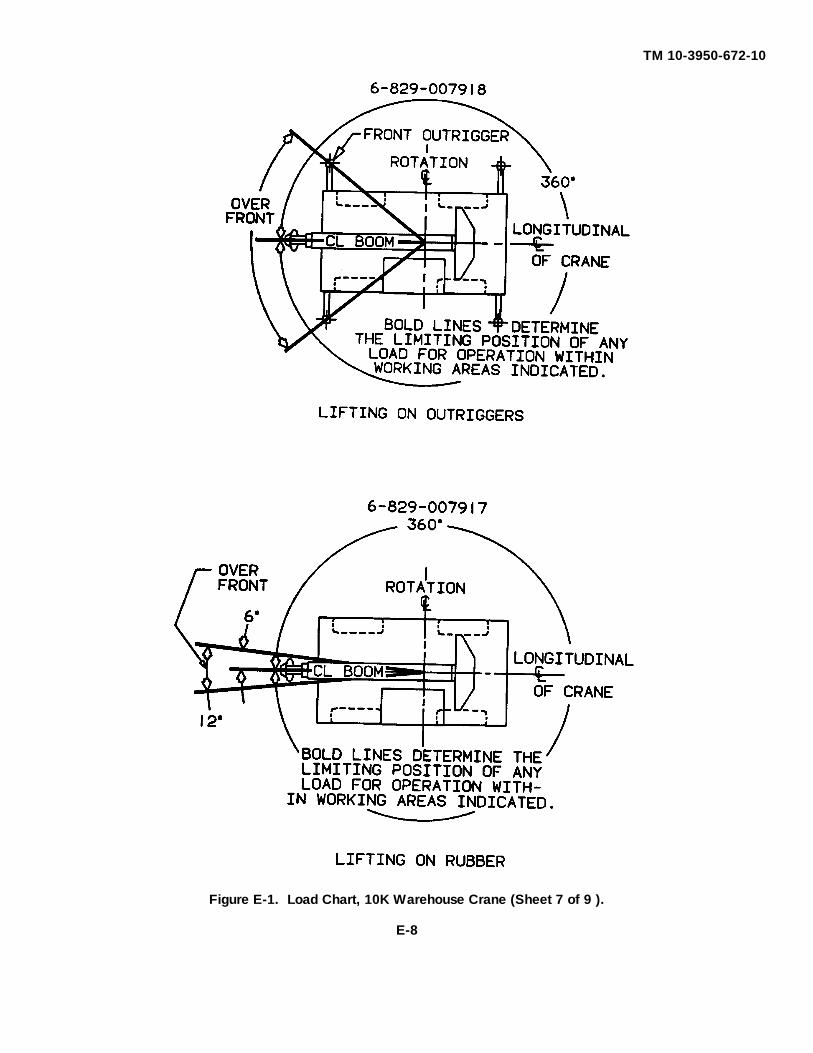
TM 10-3950-672-10
Figure E-1. Load Chart, 10K Warehouse Crane (Sheet 7 of 9 ).
E-8
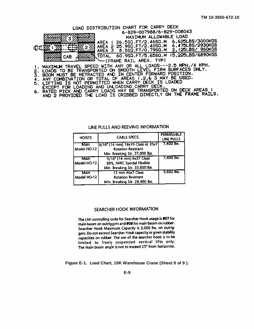
TM 10-3950-672-10
Figure E-1. Load Chart, 10K Warehouse Crane (Sheet 8 of 9 ).
E-9

TM 10-3950-672-10
Figure E-1. Load Chart, 10K Warehouse Crane (Sheet 9 of 9).
E-10

TM 10-3950-672-10
ALPHABETICAL INDEX
APage
Accessory Controls and Indicators ....................................................................................................................5-2Additional Authorization List ............................................................................................................................ C-1Air Cleaner, Check Condition of Indicator .......................................................................................................5-15Alternator Charging Indicator ............................................................................................................................5-6Antifreeze & Coolant, Check for Proper Level ................................................................................................5-13Antitwo-block System .......................................................................................................................................4-4Antitwo-block System, Check for Proper Operation ........................................................................................5-20Axles ................................................................................................................................................................4-2
B
Backup Alarm ..................................................................................................................................................5-8Basic Issue Items ............................................................................................................................................ B-1Battery ...........................................................................................................................................................5-20Battery, Operator Inspection ...........................................................................................................................5-21Boom Angle Indicator, Check for Proper Operation ........................................................................................5-12Boom, Inspection ...........................................................................................................................................5-22Boom Light Switch ...........................................................................................................................................5-6Boom Assembly ...............................................................................................................................................4-3Boom Sheaves & Hook Block, Inspection .......................................................................................................5-16Brake Master Cylinder, Fluid Level Check ......................................................................................................5-21Brake System ...................................................................................................................................................4-2Brakes, Service & Parking ..............................................................................................................................5-19
C
Cab Assembly ..................................................................................................................................................4-1Cab Door Latch and Lock .................................................................................................................................5-6Cab Circulating Fan .........................................................................................................................................5-6Cab Heater, Operating ...................................................................................................................................5-35Cable Reeving ...............................................................................................................................................6-30Carrier Frame Assembly ..................................................................................................................................4-1Checking Unpacked Equipment ..................................................................................................................... 3-1Cold Weather Operation ................................................................................................................................2-23Cold Weather Starting ....................................................................................................................................5-24Cold Start Switch .............................................................................................................................................5-2Components of End Item ................................................................................................................................. B-1Controlled Free-fall Hoist ...............................................................................................................................2-17Control Levers & Linkage, Check for Proper Operation ..................................................................................5-20Control Panel Gauges, Check for Proper Operation .......................................................................................5-19Controls and Indicators .....................................................................................................................................5-1Converter Oil Temperature Gauge ...................................................................................................................5-1Coolant & Antifreeze, Check for Proper Level ................................................................................................5-13
INDEX-1
TM 10-3950-672-10
ALPHABETICAL INDEX (continued)
C (continued)Page
Counterweight, Inspection ..............................................................................................................................5-21Crane Controls and Indicators ..........................................................................................................................5-6Crane Travel Operation ..................................................................................................................................5-25Craning Operation ............................................................................................................................................2-8
D
Deprocessing Unpacked Equipment .................................................................................................................3-1Dome Light ......................................................................................................................................................5-5Don't Forget ...................................................................................................................................................2-24Drive Train .......................................................................................................................................................4-2Driving the Crane ...........................................................................................................................................5-26
E
Electrical Hazards ..........................................................................................................................................2-18Electrical System .............................................................................................................................................4-4Elevating the Boom ........................................................................................................................................5-31Emergency Load Lowering Procedures ..........................................................................................................5-34Engine .............................................................................................................................................................4-1Engine Controls and Indicators .........................................................................................................................5-1Engine Coolant, Check for Proper Operation ..................................................................................................5-13Engine Coolant Temperature Gauge ................................................................................................................5-1Engine Crankcase, Oil Level Check ...............................................................................................................5-14Engine Oil Pressure Gauge ..............................................................................................................................5-1Exhaust System, Inspection ...........................................................................................................................5-22Expendable/Durable Supplies and Materials List ............................................................................................. D-1Extending the Boom .......................................................................................................................................5-32
F
Fan Belts, Inspection ......................................................................................................................................5-22Fire Extinguisher ..............................................................................................................................................5-6Fire Extinguisher, Check Charge Indicator .....................................................................................................5-12Foot Brake Pedal .............................................................................................................................................5-6Foot Throttle Pedal ..........................................................................................................................................5-2Fuel Filter/Water Separator, Draining .............................................................................................................5-18Fuel Quantity Gauge ........................................................................................................................................5-1Fuel Tank .........................................................................................................................................................4-1Fuel Tank and Lines, Inspection .....................................................................................................................5-18Fuels, Recommended ....................................................................................................................................5-11Functional Check ...........................................................................................................................................5-27
INDEX-2
TM 10-3950-672-10
ALPHABETICAL INDEX (continued)
GPage
General Crane Operation ...............................................................................................................................5-27
H
Heater/Defroster ...............................................................................................................................................4-4Heater/Defroster Air Temperature Control ........................................................................................................5-6Heater/Defroster Fan Switch ............................................................................................................................5-6Hoist ................................................................................................................................................................4-3Hoist Control Lever ..........................................................................................................................................5-7Hoist Drum & Motor, Check for Proper Operation ...........................................................................................5-17Hook Block & Boom Sheaves, Inspection .......................................................................................................5-16Horn Button Switch ..........................................................................................................................................5-2Hourmeter ........................................................................................................................................................5-2Hydraulic Cylinders & Valves, Inspection .......................................................................................................5-22Hydraulic Lines, Hoses, and Fittings, Inspection .............................................................................................5-21Hydraulic Oil Cooler, Check for Leaks ............................................................................................................5-16Hydraulic Oil Recommendations .................................................................................................................... 6-3Hydraulic Reservoir, Fluid Level Check ..........................................................................................................5-15Hydraulic Systems and Components ................................................................................................................4-2
I, J ,K
Ignition Switch ..................................................................................................................................................5-1Installing Cable on the Hoist ...........................................................................................................................6-29Installing Wedge and Socket ..........................................................................................................................6-31Introduction ......................................................................................................................................................1-1
L
Level Indicator .................................................................................................................................................5-6Lift Control Lever .............................................................................................................................................5-7Lights/Horn, Check for Broken Lenses ............................................................................................................5-12Lights Switch ....................................................................................................................................................5-5List of Specifications ........................................................................................................................................1-1Load Chart ...................................................................................................................................................... E-1Low Oil Pressure/High Engine Temperature Indicator ......................................................................................5-2Lowering the Boom ........................................................................................................................................5-32Lowering Hoist Cable .....................................................................................................................................5-33Lubrication Instructions ....................................................................................................................................6-1Lubrication Chart ..............................................................................................................................................6-5Lubrication Points .............................................................................................................................................6-5Lubrication Symbols .........................................................................................................................................6-1
INDEX-3

TM 10-3950-672-10
ALPHABETICAL INDEX (continued)
M and NPage
Maintenance Instructions ..................................................................................................................................6-1Major Components and Systems ......................................................................................................................4-1Normal Engine Starting ..................................................................................................................................5-23Notes for Lifting Capacities ............................................................................................................................. E-3
O
Operating Cab Heater ....................................................................................................................................5-35Operating Procedures ....................................................................................................................................5-23Operator's Seat Controls ..................................................................................................................................5-6Operator Troubleshooting Table .....................................................................................................................6-13Outrigger Control Lever ....................................................................................................................................5-7Outrigger Float Pads, Proper Installation ........................................................................................................5-12Outrigger Selector Switch (Right and Left Side) ...............................................................................................5-7Outrigger System .............................................................................................................................................4-3
P, Q
Panel Lamp ......................................................................................................................................................5-5Park Brake Indicator .........................................................................................................................................5-8Park Brake Lever .............................................................................................................................................5-7Personnel Platforms .......................................................................................................................................2-23PMCS Chart ...................................................................................................................................................5-12Preliminary Servicing and Adjustment ..............................................................................................................3-1Preparation for Use ..........................................................................................................................................3-1Preventive Maintenance Checks and Services (PMCS) ...................................................................................5-8Principles of Operation .....................................................................................................................................4-1
R
Raising the Hoist Cable ................................................................................................................................. 5-34Recommended Crane Shutdown Procedures ............................................................................................... 5-34References ..................................................................................................................................................... .A-1Reporting Errors ................................................................................................................................................... iRetracting the Boom .................................................................................................................................... 5-33
S
Safety Precautions ...........................................................................................................................................2-1Seat Belt, Inspection ......................................................................................................................................5-17Setting the Outriggers ....................................................................................................................................5-30Shutdown Procedure ......................................................................................................................................5-24Spotlight ...........................................................................................................................................................5-6Steering System ...............................................................................................................................................4-2
INDEX-4

TM 10-3950-672-10
ALPHABETICAL INDEX (continued)
S (continued)Page
Stowing the Outriggers ...................................................................................................................................5-30Summary .........................................................................................................................................................3-1Swing Brake, Check for Proper Operation ......................................................................................................5-20Swing Control Lever .........................................................................................................................................5-7Swinging the Boom ........................................................................................................................................5-31Swivels ............................................................................................................................................................4-3Symptom Index ..............................................................................................................................................6-12
T
Telescope Control Lever ..................................................................................................................................5-7Terms to Know When Using Load Chart .........................................................................................................5-28Tire Inflation Chart ..................................................................................................................................... . E-10Tire Pressures ............................................................................................................................................... E-10Tires, Inspect for Wear ...................................................................................................................................5-12Transmission Control Lever (1-2-D-N-R) ..........................................................................................................5-7Transmission, Fluid Level Check ....................................................................................................................5-14Transportation and Lifting Decal .......................................................................................................................1-6Travel Operation ..............................................................................................................................................2-7Troubleshooting .............................................................................................................................................6-12Turn Signal/Four-Way Flasher .........................................................................................................................5-2Turntable Assembly and Swing Mechanism .....................................................................................................4-3Two-block Indicator ..........................................................................................................................................5-8Two-block Lockout Override .............................................................................................................................5-8
U
Unpacking ........................................................................................................................................................3-1Using Load Chart ...........................................................................................................................................5-28
V
Voltmeter .........................................................................................................................................................5-2
W, X, Y, ZPage
Windshield Washer Bottle Fluid Level Check .................................................................................................5-17Windshield Wiper/Washer Switch ....................................................................................................................5-5Wire Rope, Inspection ....................................................................................................................................5-16Wire Rope and Sheaves ................................................................................................................................2-13Wire Rope Lubrication ....................................................................................................................................6-10
INDEX-5/(INDEX-6 blank)


PIN: 075545-000

This fine document...
Was brought to you by me:
Liberated Manuals -- free army and government manuals
Why do I do it? I am tired of sleazy CD-ROM sellers, who take publicly available information, slap “watermarks” and other junk on it, and sell it. Those masters of search engine manipulation make sure that their sites that sell free information, come up first in search engines. They did not create it... They did not even scan it... Why should they get your money? Why are not letting you give those free manuals to your friends?
I am setting this document FREE. This document was made by the US Government and is NOT protected by Copyright. Feel free to share, republish, sell and so on.
I am not asking you for donations, fees or handouts. If you can, please provide a link to liberatedmanuals.com, so that free manuals come up first in search engines:
<A HREF=http://www.liberatedmanuals.com/>Free Military and Government Manuals</A>
– SincerelyIgor Chudovhttp://igor.chudov.com/
– Chicago Machinery Movers