Technical manual - NHP Electrical 2... · WIRING DIAGRAMS ... • Phase to phase voltage measure...
32
Technical manual: Automatic Transfer Switch Controller: Model TL101 I217GB09 06 31100081
Transcript of Technical manual - NHP Electrical 2... · WIRING DIAGRAMS ... • Phase to phase voltage measure...

Technical manual:
Automatic Transfer Switch Controller: Model TL101
I217
GB09
06
3110
0081

Temlogic 2 TL101 Controller Manual
ii
TABLE OF CONTENTS
1.0 WORKING PRINCIPAL……………………………………………………………………………………... 1
2.0 TECHNICAL FEATURES…………………………………………………………………………………... 1
3.0 UNIT OPERATING FEATURES………………………….………………………………………………... 2
3.1 OPERATING CHARACTERISTICS……………………………………………………………………… 2
3.2 PROGRAMMABLE FUNCTIONS ……………………………………………………………………….. 2
3.3 TRANSFER EQUIPMENT CAPABILITY………………………………………………………………… 2
4.0
TECHNICAL CHARACTERISTICS………………………………………………………………………...
3
5.0 FRONT PANEL DESCRIPTION …………………………………………………………………………… 4
6.0 MEASURE VARIABLE SELECTION……………………………………………………………………… 5
7.0 STATUS LEDs……………………………………………………………………………………................ 6
8.0 OPERATING MODE SELECTION……………………………………………………………………….… 7
8.1 OFF-RESET MODE……………………………………………………………………………………...... 7
8.2 MANUAL MODE……………………………………………………………………………………........... 7
8.3 AUTO MODE……………………………………………………………………………………................ 8
8.4 TEST MODE……………………………………………………………………………………................. 8
9.0
MAIN LINE FAILURE SIMULATION……………………………………………………………………….
9
10.0 APPLICATION OPERATION……………………………………………………………………………….. 9
10.1 UTILITY-TO-GENERATOR APPLICATION…………………………………………………………….. 9
10.2 UTILITY-TO- UTILITY APPLICATION…………………………………………………………………... 10
10.3 GENERATOR -TO- GENERATOR APPLICATION……………………………………………………. 10
10.4 EJP FUNCTION……………………………………………………………………................................. 10
11.0
CONTROL OF CHANGEOVER DEVICES………………………………………………….……………..
10
11.1 CONTROL OF MOTORISED CIRCUIT BREAKER……………………………………………………. 11
11.2 CONTROL OF MOTORISED CHANGEOVER SWITCHES………………………………….……….. 11
11.3 CONTROL OF CONTACTORS…………………………………………………….…………………….. 11
12.0
PROGRAMMING OF CONTROLS / PARAMETERS………………………………………………….…
12
12.1 VOLTAGE CONTROLS…………………………………………………………………………………... 12
12.2 PARAMETER MENUS ………………………………………………………………………………….... 14
12.3 PARAMETER SETUP …………………………………………………………………………………..... 22
12.4 REAL-TIME CLOCK SETUP …………………………………………………………………………….. 23
13.0
OUTPUT DATA / TESTS / REMOTE CONTROL…………………………………………………………
24
13.1 DISPLAY OF STATISTICAL DATA……………………………………………………………………… 24
13.2 ALARMS………………………………………………………………………………….......................... 25
13.3 AUTOMATIC TEST…………………………………………………………………………………......... 26
13.4 DIAGNOSTIC MESSAGE………………………………………………………………………………… 26
13.5 KEYPAD LOCK…………………………………………………………………………………............... 27
13.6 REMOTE CONTROL…………………………………………………………………………………....... 27
14.0
MECHANICAL DIMENSIONS & CUT- OUTS…………………………………………………………….
28
15.0
WIRING DIAGRAMS…………………………………………………………………………………….......
28
I217
GB09
06
3110
0081

Temlogic 2 TL101 Controller Manual
1
1.0 WORKING PRINCIPAL
The Temlogic 2 TL101 automatic transfer switch controller will control & supervise the primary & secondary power of an installation and initiate transferring of the mains to a back-up source in the
event of main source interruption. The utility changeover, from one power source to the other can be
fully automatic or manually operated. The logic controller includes all necessary features to monitor energy distribution systems or generating sets, and relative transfer equipment, such as contactors,
motorised circuit breakers and changeover switches.
The automatic transfer takes place when predefined conditions entered by the user take place such as,
• The need for a reliable power source
• Power supply voltage/frequency etc. not falling within programmed limits
• The need to use the most economical power source
The unit is simply programmed from the front panel with visual led indication and can be remotely
monitored via a Modbus network. The circuit breakers can be manually controlled using the function
keys on the front face of the controller. The list below details typical applications.
Utility-utility, utility to generator or generator to generator
changeover
Control of motorised circuit breakers, motorised switches or contactors
Generator management with automatic test and rotation
emergency
Three phase, two phase or single-phase voltage controls L-L voltage and/or L-N voltage control
Controls of minimum voltage, maximum voltage, phase
loss, asymmetry, minimum frequency, maximum frequency, with independent enable and delay
2.0 TECHNICAL FEATURES
• Flush mount 144*144 mm housing
• Plug in removable connections
• AC Rated auxiliary power supply: 220-230-240VAC
• DC Rated auxiliary power supply: 12-24-48VDC
• Phase to phase voltage measure inputs: 80-800VAC
• Voltage transformer programming
• TRMS voltage measure
• Frequency measurement 45-65Hz
• Control function: phase sequence, phase loss, max/min voltage,
asymmetry, max/min frequency
• Two displays for voltage/frequency viewing
• 8 digital programming inputs
• 7 relay programmable outputs
• RS232 interface
I217
GB09
06
3110
0081

Temlogic 2 TL101 Controller Manual
2
3.0 UNIT OPERATING FEATURES
3.1 Operating Characteristics
Choice of single, two, three-phase lines with or without neutral Supported applications include mains-mains, mains-genset and genset-genset Controls include
- Phase loss - Phase sequence - Min/Max voltage - Asymmetry - Min/Max Frequency
Statistical data logging - Number of automatic/manual transfers of line 1 & 2 - Number of incomplete transfers of line 1 & 2 - Time of line 1 & 2 voltage out of limits - Time of line 1 & 2 voltage normal - Time of utility power supply on line 1 & 2 - Time of no utility power supply
Event logging with time and date entry: source of automatic transfer control, automatic/manual & incomplete transfer controls, operating mode change and setup data variations
Data and event storage in non-volatile ferromagnetic memory keypad setup Modbus RTU and ASCII communication protocols
3.2 Programmable functions
Automatic test Transfer strategy Signal & genset starting supervision Two generator rotation Principle line selection Secondary loads disconnection Before & after transfer indication
3.3 Transfer equipment capability
Contactors Motorised circuit breakers Motorised changeover switches
I217
GB09
06
3110
0081

Temlogic 2 TL101 Controller Manual
3
4.0 TECHNICAL CHARACTERISTICS
Auxiliary power supply DC supply operating limits 9…70VDC (Us=12-24-48VDC) AC supply operating limits 187…264VAC (Us=220-230-240VAC)
Frequency 45…65Hz Power consumption max. 6VA (Us=240VAC)
Power dissipation max 2.8W (Us= 240VAC or Us=48VDC) Current consumption max 420mA at 12VDC; 200mA at 24VDC
Micro-breaking immunity time 50ms Voltage inputs
Rated voltage Ue 690VAC phase-phase (400VAC phase-neutral) Measure limits 80…800VAC phase-phase
Frequency limits 45…65Hz Type of measure TRMS (True Root Mean Square value)
Measure input impedance >1.1M phase-phase; >0.5M phase-neutral Type of connection One, two or three phase
Measure error Class 0.5 ±0.25% f.s. ±1digit Digital inputs
Number of inputs 8 (all programmable) Type of input Negative Input current 9mA
Input signal “0” state 1.5 (2.9V typical) Input signal “1” state 5.3 (4.3V typical)
Input signal delay 50msec Relay outputs
Number of outputs 7 (all programmable) Number of control outputs for circuit breaker closing and pre-
charging 2 (1 N/O – 12A/230VAC) (relay contacts with 16A
capacity in AC1) Number of control outputs for circuit breaker closing 2 relays (1 N/O – 8A/230VAC)
Number of control outputs for generating set 1 relay (1 N/O – 8A/230VAC) Number of spare outputs 1 relay (1 C/O – 8A/230VAC) Number of alarm outputs
1 relay (1C/O – 8A/230VAC)
Max current 1.2 and 2.2 terminals 12A Communication interfaces
RS232 serial port Programmable baud-rate 1200…38400 bps Connection with RJ6/6 jack
RS485 serial port (NON STANDARD) Opto-isolated, programmable baud-rate 1200…38400 bpsPlug-in / removable terminal connection
Real time clock (NON STANDARD) Time of backup energy Capacitor (Super Cap)
Operating autonomy without power supply 7 days Insulation
Rated insulation voltage Ui 690V Ambient conditions
Operating temperature -20…+60°C Storage temperature -30…+80°C
Relative humidity <90% Pollution degree maximum 2
Connections Type of terminal Plug-in / removable
Conductor section min / max 0.02…2.5 mm (24 – 12 AWG) Tightening torque 0.5 Nm (4.5 lbin)
Housing Material LEXAN 3412R thermoplastic Version Flush mount
Dimensions l x h x d 144 x 144 x 94mm Degree of protection IP41 on front, IP20 rear
Weight 950g Table 1: Technical characteristics
I217
GB09
06
3110
0081

Temlogic 2 TL101 Controller Manual
4
5.0 FRONT PANEL DESCRIPTION
The TL101 Temlogic 2 controller offers full transfer control, parameter alteration and measure variable
display via the panel function keys and LED displays.
Front panel summary:
• LED displays: Measure variables (voltages & frequency) can be viewed via the two LED displays.
The ‘Line 1’ LED display would typically represent the ‘normal’ or ‘main’ power source and the ‘Line
2’ LED display would typically represent the ‘emergency’ or ‘back-up’ power source.
• Measure variable LEDs: These display LEDs indicate for each line whether the LED display is showing a line-to-line (L-L), line-to-neutral (L-N) or frequency reading.
• Scroll Keys: The ‘Scroll keys’ enable the user to switch between the available measure variables
(L-L, L-N, frequency) which are shown via the LED display. • Mimic diagram: Is a visual representation of the transfer switch system.
• Line Status LEDs: Indicate whether a supply (normal or emergency) is ready for electrical
connection to a load.
• LINE 1 / LINE 2 ON/OFF Keys: Allows the manual control of the motorised circuit breaker. • ON/WITHDRAWN/TRIP Status LEDs: Indicates the status of the circuit breaker.
• Alarm Status LED: Indicates an alarm event has occurred.
• Test Status LED: Indicates the status of the automatic test function. • Operation mode keys: Four keys ‘OFF RESET’, ‘MANUAL’, ‘AUTO’ and ‘TEST’ which allow
selection of the desired operating mode.
I217
GB09
06
3110
0081

Temlogic 2 TL101 Controller Manual
5
6.0 MEASURE VARIABLE SELECTION
The SCROLL keys are the only operators required to select a desired measure
variable. Each line has its own SCROLL key and when pressed repeatedly the line-to- line (L-L) voltage, line-to-neutral (L-N) voltage or frequency information are shown
on the corresponding line LED display.
Each time a line SCROLL key is pressed the red measure variable LED
combinations for the corresponding line will indicate the measure variable selected.
Configuring the TL101 controller to either three-phase, two-phase or single-phase
control will vary the list of measures.
Example: Typical 3 phase, 4 line system.
After 1 minute without pressing a SCROLL key the measure will revert to the default measure.
During an alarm event the alarm code will occupy the display. Pressing the SCROLL key will mask the
alarm temporarily and allow the measures to be accessed.
I217
GB09
06
3110
0081

Temlogic 2 TL101 Controller Manual
6
7.0 STATUS LEDs
There are six categories of status LED presented on the front panel which indicate the status of the unit
and/or the circuit breaker it controls. The categories are:
• Line Status LED
• ON Status LED
• WITHDRAWN Status LED
• TRIP Status LED • Alarm Status LED
• Test Status LED
The table below details the meaning of the different status LEDs. Some LEDs can alternate between two
colours and have a different meaning depending on the colour.
LED ON OFF FLASH
LINE OK
Voltage and frequency
within set limits
Voltage or frequency off
limits
Presence delay time or
failure in progress
Operating circuit breaker (green)
ON ❶
Closed circuit breaker (green)
Open circuit breaker
Timeout (red)
WITHDRAWN ❷
Circuit breaker
withdrawn
Circuit breaker inserted
ok
Circuit breaker
withdrawn alarm
TRIP ❷
Trip signal without alarm No protection intervention
Protection intervention alarm
ALARM –– No active alarm One or more active alarms
TEST Automatic test enabled
(green)
Automatic test disabled
Automatic test in
progress (green)
Calendar watch not set
(red)
❶ If auxiliary signals (feedback) have been suitably connected and programmed, the LEDs
represent the status of the circuit breakers; otherwise the LEDs represent the status of the control
outputs.
❷ If the respective signals are suitably connected and programmed, the LEDs represent the status of the
circuit breakers, if not the status LEDs will remain off.
I217
GB09
06
3110
0081

Temlogic 2 TL101 Controller Manual
7
8.0 OPERATING MODE SELECTION
The unit front panel is equipped with four Operation mode keys which allow selection of the desired operating mode. The selectable operating modes are:
• OFF RESET • MANUAL
• AUTO
• TEST
When an operation mode is selected the corresponding red LED illuminates. If the LED showing the
selected operating mode flashes, this indicates that the unit is communicating through the serial interface
which may result in commands being preformed via remote.
8.1 OFF-RESET MODE
• The unit is disabled in this mode and does not perform any functions. Status & measure
LED’s remain active.
• If the changeover devices (ie motorized circuit breakers) are pulse-type controlled, in OFF-
RESET both controls remain disabled. For continuous – type controlled changeover devices the behavior is determined by the P2.25 programming.
• To access the programming menus it is necessary to select the OFF-RESET mode before
commencing. • By pressing the OFF-RESET key retentive alarms can be cleared, provided the conditions
generating the alarms have been addressed.
8.2 MANUAL MODE
• In MANUAL mode it is possible to control circuit breakers manually by pressing the relevant
line ON/OFF key (YELLOW COLOUR KEY’S) for a minimum time of 300ms.
• At each key pressure the circuit breaker status is switched over. The command is accepted
only when 1sec has elapsed from the end of the previous switching. • If a manual command is given to close a circuit breaker while its paired circuit breaker is still
closed, the TL101 unit will first open the currently closed circuit breaker and then close the
desired circuit breaker, while interposing the programmed interlock time. • When operating with a generator set, the generator startup and shutdown can be manually
commanded on the secondary line by pressing and holding down the MANUAL key for 5
seconds.
I217
GB09
06
3110
0081

Temlogic 2 TL101 Controller Manual
8
8.3 AUTO MODE
• In the AUTO mode the TL101 unit performs both circuit breaker opening and closing
operations, and manages the startup and shutdown of the generator set, if any.
• When the main line exceeds the limits, after the set delay times (line LED off), the unit disconnects the load from the main line and connects it to the secondary line. Both the
startup of the generator set (if any), and the handling and interlock times between circuit
breakers are controlled via the TL101 unit.
• The TL101 unit may be programmed to disconnect the load from the main line before or after the secondary line has been made available.
• When the main line returns within the limits, the Tl101 unit switches over the load again and
controls the generator set cooling cycle, if any. • Automatic operating cycles vary both as a function of the type of application (utility-to- utility,
utility-to-generator or generator-to-generator) and as a function of the type of switching
devices used (motorised circuit breakers, switches or contactors).
8.4 TEST MODE
• The TEST mode allows the TL101 unit to confirm the proper operation of the emergency
generator set while a normal operating main line power source is available. • When TEST mode is selected the generator set on the secondary line is immediately
started.
• Both voltage controls are activated and, if an anomaly occurs on the main line during the test, the load is switched over automatically.
• Under standard conditions when the main line is present, the load remains on the line and
the generator set works with no load (offload test). • To test the emergency generator under load (on-load test), the operation mode key ‘TEST’
and line 2 ‘ON/OFF’ MUST BE PRESSED TOGETHER FOR 5 SECONDS.
• Once the load has been shifted to the generator under TEST mode, in the event of a main
line failure or if an on-load test is being performed, the TL101 unit will not automatically revert back to the main line, unless the AUTO mode is selected.
• Delay and interlock times are the same as in the automatic mode.
I217
GB09
06
3110
0081

Temlogic 2 TL101 Controller Manual
9
9.0 MAIN LINE FAILURE SIMULATION
For the purpose of system testing it is possible to simulate a 1 minute voltage failure on the main line.
The unit will respond in the same manner and timeframe set for standard automatic operation. The proper operation of transfer cycles may thus be controlled. To perform a main line failure simulation:
• Set the TL101 unit for automatic operation by selecting the AUTO key.
• Press the AUTO key and the line 2 ON-OFF key together for 10
consecutive seconds.
• The letters F.SI (Failure Simulation) will appear on the display during the execution of the whole
cycle.
• To stop the test before completion, repeat the starting procedure or switch to the OFF – RESET
mode.
10.0 APPLICATION OPERATION
10.1 UTILITY-TO-GENERATOR APPLICATION
When configured for use in a utility-to-generator application (U-G, default setting) the load is usually
connected to the utility (Line 1). After a voltage or frequency anomaly the following occurs:
• A start signal is sent to generator (Line 2) after the delay set in P2.15,
• The generator is allowed to run ‘off-load’ until the voltage levels are within programmed limits, at
which time the load is connected to the generator line.
• The TL101 unit continually monitors the main utility line for standard values to return. • When the main utility line stabilises the load is transferred back to the utility line and the generator
is kept in operation without load for a time set by P2.16 to allow it to cool.
• The TL101 unit then sends a start/stop command to the generator through a relay output. The TL101 unit can receive digital signals from the generator indicating its status (generator ready, ok
to load taking, etc) through programmable inputs.
• An automatic test can be programmed, i.e. the generator can be started at set times to control its operation even if the utility is generally within limits, by setting execution interval, starting time,
days of the week when the test shall be carried out, its duration, etc.. Refer to the relevant menu to
set the automatic test.
+
I217
GB09
06
3110
0081

Temlogic 2 TL101 Controller Manual
10
10.2 UTILITY-TO- UTILITY APPLICATION
When configured for use in a utility-to-utility (U-U) application, the load is usually connected to the main
utility and the transfer to the secondary utility occurs if/when a main line anomaly occurs or a transfer
signal is remotely given.
10.3 GENERATOR -TO- GENERATOR APPLICATION
Generator – to – generator applications involve controlling two generators, each with a start-stop relay and
possible feedback signals.
• In this application a rotation between generators can be programmed, i.e. the load can be shifted
from one to the other at regular intervals, with the purpose of dividing the generator work load
equally. • It is possible to set the time of day when rotation shall occur, so that load supply cut-off occurs at a
specified time.
• If a problem occurs with either generator, the load is shifted to the stand-by unit in all cases.
10.4 EJP FUNCTION
For applications requiring the EJP function, it is possible to use two programmable inputs set to functions
S.GE (start generator) and E.tr (External transfer).
• Parameter P2.26 can also be used to define a generator start delay.
11.0 CONTROL OF CHANGEOVER DEVICES The TL101 unit can control different types of devices such as motorised circuit breakers, motorised
changeovers or contactors for the purpose of line changeover. Depending on the type of changeover devices used with the TL101 unit, appropriate wiring diagrams shall be used with related programming of
programmable inputs /outputs.
• Programmable outputs are set by default for motorised circuit breaker applications. For further
details please refer to the attached wiring diagrams at the end of this manual.
• The device status feedback inputs shall be normally wired, so as to ensure reliable system
operation. Nonetheless, it is however possible to avoid their wiring and set programmable inputs for other functions. In this case the unit behaves as if the device carried out at once the command sent.
• If the device status inputs are not used, after power-on the TL101 unit will send an open command
in order to set the switching devices to a definite position. • If the device status inputs are used, after power-on the TL101 unit will not send commands to the
switching device until the relative line status is not stable, that is when the presence / absence
delay have elapsed. • Internal control relays are neither interlocked electrically nor mechanically.
I217
GB09
06
3110
0081

Temlogic 2 TL101 Controller Manual
11
11.1 CONTROL OF MOTORISED CIRCUIT BREAKER
• For the control of motorised circuit breakers, 4 outputs are needed (open and close commands for line 1and line 2) and two inputs for circuit breakers status feedback, plus any additional optional inputs foralarm signaling (WITHDRAWN and TRIP).
� • Open and close commands can be kept in continuous or pulse mode, i.e. kept until the circuit breaker has reached the required position + safety time.
� • The two command modes ("Con" - continuous or "PUL" - pulse) can be selected through the appropriateparameter P2.07 in the general data menu.
� • TRIP inputs are ignored for a 15-second window every time an open command is sent to the circuit breakers. This prevents a false alarm from being activated if a circuit breakers temporarily sends a TRIP signal during the opening operation initiated by the release coil.
• A 0.5-second interval is interposed between the opening and closing commands of the samecircuit breaker.• If feedback inputs are used, should the circuit breaker not close, a second attempt is conducted before generating the alarm.
11.2 CONTROL OF MOTORISED CHANGEOVER SWITCHES
Applications utilising motorised switches are configured in a similar fashion to that of motorized circuit breakers, with the following exceptions:
� • Only three outputs (line1, line 2 and all open positions) and two inputs for circuit breaker status are required
� • CL.1, CL.2 and OP.A output functions and Fb.1 and Fb.2 input functions are required. � • It is possible to select the command mode (either pulse or continuous).
11.3 CONTROL OF CONTACTORS
• If a pair of contactors are used, two outputs (CL.1 and CL.2) and two status inputs are required. • In this case, the command must be programmed in contactors control mode (P2.07 = Cnt).
I217
GB09
06
3110
0081

Temlogic 2 TL101 Controller Manual
12
12.0 PROGRAMMING OF CONTROLS / PARAMETERS
12.1 VOLTAGE CONTROLS
A po
• At power up or resetting of the device, each line is considered stable when the voltage is within pickup limits, unless the relative circuit breaker is already closed.
wer source is determined to be suitable or unsuitable for use by the TL101 unit based upon user defined parameters. The menus used to establish a power sources suitability are:
�• menu P
�
1 (system ratings) � • menu P3 (line 1 voltage control) � • menu P4 (line 2 voltage control)
The systems ratings can be set through menu P1, including rated voltage and frequency, which are issued as references to set percent thresholds. A voltage ratio (TV ) can be set whenever a voltage lower than the actual system voltage is applied to the TL101 unit voltage inputs. Also in this case, both the visualisation and the setting of thresholds will be implemented in actual magnitudes referred to the system. The controller can be programmed to perform voltage controls on three-phase with or without neutral, two-phase or single-phase utilities (P1.03). In the case of three-phase or two-phase utilities the L-L voltage, L-N voltage, or both (P1.04) can be monitored. In every case, the rated voltage set within P1.01 has to be equal to the phase-to-phase voltage.
The following table lists the controls made on each line. The controls marked with OFF may be excluded. Control Description OFF
� � �
� � �
All controls, except minimum voltage, may be excluded independently, by setting the relevant parameters to OFF.
I217
GB09
06
3110
0081
Minimum
voltage
One or more phases are too low
Maximum voltage
One or more phases are too high ●
Phase loss
Threshold below which the unit intervention is quicker than with a normal
decrease
●
Asymmetry (unbalance)
Phases within the maximum-minimum range but too different from each other ●
Minimum frequency
Frequency is too low
●
Maximum
frequency
Frequency is too high ●
Phase sequence
Reverse rotation of phases
●

Temlogic 2 TL101 Controller Manual
13
Each listed anomaly has an independent delay time. For the TL101 unit to respond to an anomaly, the
event must continually persist uninterrupted more than the set delay time.
When all the line parameters are restored within the specified limits, before the line may be used, the line presence delay time must elapse. The duration of this time is specified by two independent parameters:
1) the delay time when the alternate line becomes available, and
2) the delay time, which is normally of shorter duration, that exists in the situation where the alternate line is not available.
Voltage minimums / maximums:
The limits of minimum and
maximum voltage are specified by setting two thresholds, each one
defining the point beyond which
the voltage is considered no longer acceptable (e.g. P3.01,
drop-out) and the other, nearer to
the rated voltage, defining the
point where it is again compatible (e.g. P3.02, pick-up).
The distance between these two thresholds defines hysteresis. For example, it could be stated that below 80% of the rated voltage value, the voltage source can no longer be used. For the voltage source to be
deemed satisfactory, the voltage must rise above 85%, thus defining a 5% hysteresis (dead-band). The
same principle is applied to maximum voltage.
Frequency thresholds: Voltage source frequency thresholds allow for a fixed hysteresis which is equal to 1% of rated frequency.
Phase loss: For the phase loss, the pick-up threshold is the same as the minimum voltage pickup threshold.
I217
GB09
06
3110
0081

Temlogic 2 TL101 Controller Manual
14
12.2 PARAMETER MENUS
The TL101 unit has eight menus that can be accessed in order to change the operational and functional parameters of the TL101. The menus are structured as shown below:
MENU Description
P1 System Ratings
P2 General Data
P3 Line 1 Voltage control
P4 Line 2 Voltage control
P5 Programmable Inputs
P6 Programmable Outputs
P7 Communication Ports
P8 Automatic Test
Each of the eight parameter menus contain a list of changeable parameters, functions and input / outputs. These are summarised below:
MENU P1 - RATINGS
PARA. FUNCTION RANGE DEFAULT
P1.01 System rated voltage 100...690VAC
415VAC
P1.02 TV ratio 1.00 ... 9.99
1.00
P1.03 Wiring configuration 3.nE - 3 phase + Neutral 3Ph – 3 phase 2Ph- 2 phase 1Ph – single phase
3.nE
P1.04 Type of voltage control L-L - Line – to Line L-N – Line – to - Neutral LLn - Line – to Line + Line – to Neutral
L-L
P1.05 Rated frequency 50H - 50Hz 60H - 60Hz
50Hz
P1.06 Rated battery voltage OFF
12 - 12VDC 24 - 24VDC 48 - 48VDC
OFF
P1.01 - Rated voltage used for threshold calculation; thresholds are expressed as Un percentage. Set the
line-to-neutral (L-N) or line-to-line (L-L) voltage depending on what was set on P1.04. P1.03 - Defines the network wiring configuration used. The setting between 3- phase and 3-phase +
neutral influences the visualisation only.
P1.04 - Specifies if the voltage controls are applied to L-L voltages, to L-N voltages or to both voltages. P1.05 - Rated frequency used as reference for frequency threshold calculation.
P1.06 - Used for alarms on battery voltage.
I217
GB09
06
3110
0081

Temlogic 2 TL101 Controller Manual
15
MENU P2 – GENERAL DATA PARA. FUNCTI ON RANGE DEFAULT
P2.01 Type of application U-G = Utility to Generator U-U = Utility to Utility G-G = Generator to Generator
U-G
P2.02 Phase sequence control OFF - Disabled L1-L2-L3 - Direct L3-L2-L1 - Inverse
L1-L2-L3
P2.03 Main line selection -1- Line 1 -2- Line 2
-1-
P2.04 Interlock time Line 1 -> Line 2 0.1 ... 90.0s 6.0s P2.05 Interlock time Line 1 <- Line 2 0.1 ... 90.0s 6.0s P2.06 Changeover strategy ObP - Open Before
Presence OAP - Open After Presence
ObP
P2.07 Circuit breakers control type Con - Continuous PUL - Pulse Cnt - Contactors
PUL
P2.08 Maximum time for circuit breaker operation (A03 - A04 Alarms delay) 1...900s
5s
P2.09 Open command duration 1.0...60.0s 10.0s P2.10 Close command duration 1.0...60.0s 1.0sP2.11 Maximum time for load not energized (A07 Alarm intervention delay) OFF / 1...3600s
60s
P2.12 Lock of automatic restore to main line OFF - Disabled ON - Lock on
OFF
P2.13 Pre-transfer time OFF / 1...300s OFF P2.14 Post-transfer time OFF / 1...300s
OFF
P2.15 Generator start delay 0 .... 900s
3s
P2.16 Generator cooling time 1...3600s
180s
P2.17 Generator rotation interval OFF / 1h / 2h / 3h / 4h / 6h / 8h / 12h / 1d / 2d / 3d / 4d / 5d / 6d / 7d
OFF
P2.18 Generator rotation hour 0...23
12
P2.19 Generator rotation minutes 0...59
0
P2.20 Battery minimum voltage threshold OFF / 70...100%
75%
P2.21 Battery maximum voltage threshold OFF / 110...140%
130%
P2.22 Battery threshold delay 0...60s
10s
P2.23 Clock setting at startup OFF / On
OFF
P2.24 Voltage control enable in MAN mode OFF / On
OFF
P2.25 Continuous command in RESET/OFF mode OFF - Release command output Noc - No change on command output
Noc
P2.26 EJP start delay OFF / 1..3600s OFF
P2.01 - Defines the type of application for the control of one or two generator sets, enabling the management of the relevant input/output signals.
I217
GB09
06
3110
0081

Temlogic 2 TL101 Controller Manual
16
P2.03 - Defines which is the main line, i.e. the line taking on the load when both sources are available. P2.06 - OBP (Open Before Presence) means that, in automatic mode, the open command of a circuit breaker is generated when the line concerned goes beyond limits, irrespective of the status of the alternative line. OAP (Open After Presence) means that, in automatic mode, the open command of a circuit breaker is sent only after the alternative line is present within limits. P2.07 - Defines whether open-close outputs must be continuously active (application with circuit breakerswithout feedback) or in pulse mode, i.e. activated until the circuit breaker / switch has been positioned asrequired. If in pulse mode, the command is extended for a specified time (see P2.09 and P2.10) even afterpositioning completion.If contactors are used, P2.07 must be set to "Cnt".P2.08 - If, after sending an open or close command to a circuit breaker, this is not positioned correctly within this time, alarms A03 or A04 are generated. It works when the auxiliary contacts of circuit breaker status are programmed and wired. P2.09 - minimum duration of an opening command pulse. For a motorised circuit breaker application, it must be set to a time sufficient enough to allow the load of the springs. This time is considered also when working in continuous mode. P2.10 - Duration of the opening command pulse. P2.11 - If in automatic mode both sources are not available at the same time for a time exceeding P2.11, alarm A07 is generated. P2.12 - If this parameter is enabled, after a transfer to the secondary line, restore to main line does not occur automatically whenthe latter becomes available again, but It must be commanded in manual mode. P2.13 - Excitation time of the pre-transfer output before switching from one line to the other. P2.14 - Excitation time of the post-transfer output after switching from one line to the other. P2.15 - Time elapsing between the underused line loss and the sending of the transfer signal to the generator on the alternative line. This time is independent of the circuit breaker opening time. P2.16 - Time during which the generator is left in operation to cool after it has been disconnected from the load. P2.17 - P2.18 - P2.19 - These parameters allow to implement a time rotation in G-G applications, switching the priority between the two generators. P2.17 defines the rotation interval between the two generators. The time of day when rotation will occur is defined by P2.18 and P2.19. If the rotation interval exceeds 24h, then rotation always occurs at the time stated every n days. If, on the contrary, it is less than 24h, then it occurs at the time specified and also at submultiples. For instance, if you set time at 12:30 and rotation every 6h, there will be a changeover at 12:30, one at 18:30, one at 0:30, etc. P2.23 - If the real-time-clock is not set after power-on, it returns to the default value. P2.24 - Enables or disables voltage control in MAN mode. If the control is enabled, no transfers are performed between the two lines, but the individual switching device is opened/closed when its voltage goes beyond / reverts to limits. P2.25 - Defines the behavior of the open/close command outputs when working in continuous command mode and the TL101 is in RESET/OFF mode. This parameter can be useful when working with contactors. P2.26 - Delay between the EJP start signal and the effective start signal sent to the generator.
I217
GB09
06
3110
0081

Temlogic 2 TL101 Controller Manual
17
MENU P3 – LINE 1 VOLTAGE CONTROL
PARA. FUNCTION RANGE DEFAULT
P3.01 Minimum voltage threshold - trip 70...98%
85%
P3.02 Minimum voltage threshold - restore 75...100%
90%
P3.03 Minimum voltage threshold - delay 0.1....900s
1.0s
P3.04 Maximum voltage threshold - trip 102...120% / OFF
115%
P3.05 Maximum voltage threshold - restore 100...115%
110%
P3.06 Maximum voltage threshold - delay 0.1....900s
1.0s
P3.07 Phase loss threshold 60...85% / OFF
70%
P3.08 Phase loss threshold delay 0.1...30.0s
0.1s
P3.09 Voltage unbalance threshold 1...20% / OFF
15%
P3.10 Voltage unbalance threshold delay 0.1...900s
5.0s
P3.11 Minimum frequency threshold OFF / 80...100% Fe
95%
P3.12 Minimum frequency threshold - delay 0.1...900s
5.0s
P3.13 Maximum frequency threshold 101...120% Fe / OFF
105%
P3.14 Maximum frequency threshold - delay 0.1...900s
3.0s
P3.15 Line 1 restore within limits - delay (when line 2 source not available) 1...3600s
10s
P3.16 Line 1 restore within limits - delay (when line 2 source is available) 1...3600s 60s
P3.01 - P3.02 - P3.03 - The first two parameters define the minimum voltage threshold and the related hysteresis upon restore. P3.02 cannot be set to a lower value than P3.01. P3.03 defines the intervention
delay of this protection. See paragraph Voltage Controls.
P3.04 - P3.05 - P3.06 - The first two parameters define the maximum voltage threshold and the related
hysteresis upon restore. P3.05 cannot be set to a value exceeding P3.04. Setting P3.04 to OFF will 13 disable the maximum voltage control. P3.06 defines the maximum voltage intervention delay. See
paragraph Voltage Controls.
P3.07 - P3.08 - Voltage threshold below which a phase loss intervention occurs, generally quicker than the drop. The delay for the phase loss is specified by P3.08.
P3.09 - P3.10 - P3.09 defines the maximum threshold for unbalance between phases, referred to voltage
rating, and P3.10 defines the related intervention delay. This control may be disabled by setting P3.09 to OFF.
P3.11 - P3.12 - Threshold (it may be disabled) and intervention delay for minimum frequency.
P3.13 - P3.14 - Threshold (it may be disabled) and intervention delay for maximum frequency.
P3.15 - Delay for Line 1 restore to the limit range, used when the line 2 source is not available. Generally shorter than P3.16, as there is the urgent need to supply power because the load is not energized.
P3.16 - Delay for Line 1 restore to the limit range, used when the load can be connected to line 2.
Generally longer than P3.15, as the load is energized and consequently it is possible to wait longer before considering voltage steadily restored.
I217
GB09
06
3110
0081

Temlogic 2 TL101 Controller Manual
18
MENU P4 – LINE 2 VOLTAGE CONTROL
PARA. FUNCTION RANGE DEFAULT
P4.01 Minimum voltage threshold - trip 70...98%
85%
P4.02 Minimum voltage threshold - restore 75...100%
90%
P4.03 Minimum voltage threshold - delay 0.1....900s
1.0s
P4.04 Maximum voltage threshold - trip 102...120% / OFF
115%
P4.05 Maximum voltage threshold - restore 100...115%
110%
P4.06 Maximum voltage threshold - delay 0.1....900s
1.0s
P4.07 Phase loss threshold 60...85% / OFF
70%
P4.08 Phase loss threshold delay 0.1...30.0s
0.1s
P4.09 Voltage unbalance threshold 1...20% / OFF
15%
P4.10 Voltage unbalance threshold delay 0.1...900s
5.0s
P4.11 Minimum frequency threshold OFF / 80...100% Fe
95%
P4.12 Minimum frequency threshold - delay 0.1...900s
5.0s
P4.13 Maximum frequency threshold 101...120% Fe / OFF
105%
P4.14 Maximum frequency threshold - delay 0.1...900s
3.0s
P4.15 Line 2 restore within limits - delay (when line 1 source not available) 1...3600s
10s
P4.16 Line 2 restore within limits - delay (when line 1 source is available) 1...3600s 60s
Note - For details on the functions of parameters see the previous details concerning Line 1 menu.
I217
GB09
06
3110
0081

Temlogic 2 TL101 Controller Manual
19
MENU P5 – PROGRAMMABLE INPUTS
PARA. FUNCTION RANGE DEFAULT
P5.01 Prg Input Function 1 term. 4.1 Breaker 1 closed feedback
P5.02 Prg Input Function 1 term. 4.2 Breaker 2 closed feedback
P5.03 Prg Input Function 1 term. 4.3 Breaker 1 tripped
P5.04 Prg Input Function 1 term. 4.4 Breaker 2 tripped
P5.05 Prg Input Function 1 term. 4.5 Force transfer
P5.06 Prg Input Function 1 term. 4.6 Inhibit re-transfer
P5.07 Prg Input Function 1 term. 4.7 OFF
P5.08 Prg Input Function 1 term. 4.8
SEE P5 CODE
TABLE BELOW
OFF
P5 CODE TABLE
CODE FUNCTION OFF Input not used
Fb.1
Line 1 circuit breaker closed (Feedback 1) Auxiliary contact informing the TL101 of the open/closed status of line 1 circuit breaker. If this signal is not programmed, the TL101 considers the status of the circuit breaker corresponding to the status of control outputs.
Fb.2
Line 2 circuit breaker closed (Feedback 2) Like Fb.1, referred to line 2.
tr.1
Line 1 circuit breaker protection (Trip 1) When the contact is opened, it generates an alarm of line 1 circuit breaker protection intervention.
tr.2
Line 2 circuit breaker protection (Trip 2) Like tr.1, referred to line 2.
dr.1
Line 1 circuit breaker withdrawn (Withdrawn 1) When the contact is open, it generates an alarm of line 1 circuit breaker withdrawn.
dr.2
Line 2 circuit breaker withdrawn (Withdrawn 2) Like dr.1, referred to line 2.
E.tr
Transfer to secondary line When closed, it causes the changeover to the secondary line even if main line voltage is within limits. The secondary line circuit breaker remains activated until this line remains within limits. Can be used for the EJP function.
In.r
Inhibit Return to main line
In AUTO mode, when closed, it inhibits the return to main line after it has reverted to the limit range. It is used to prevent the second power cutout due to re-transfer from occurring automatically at an unforeseeable time.
S.GE
Start Generator In AUTO mode, when closed, it causes the generator to start after the delay specified by P2.26. It can be used for the EJP function.
EME
Emergency NC contact which, if open, causes both circuit breakers to open and generates alarm A09.
Gr.1
Line 1 generator ready (Generator ready 1) When closed it signals that the generator connected to line 1 is available for use. If this signal is missing, alarm A08 is generated.
Gr.2
Line 2 generator ready (Generator ready 2) Like Gr.1.
E.L1
Enable load on line 1 (Enable Load 1)
It allows load connection on line 1, in addition to internal controls.
E.L2
Enable load on line 2 (EnableLoad 2) Like EL.1, referred to line 2.
E.C1
External control of line 1 (External control 1) Signal showing that line 1 is within limits. It replaces internal controls.
E.C2
External control of line 2 (External control 2)
Like EC.1, referred to line 2.
Loc
Keypad lock (Lock) If closed, it locks all the functions from front keypad except measure viewing.
L.PA
Lock Parameters If closed, it locks the access to setup menus.
L.rc
Lock remote control
If closed, locks write access through serial interface ports.
I217
GB09
06
3110
0081

Temlogic 2 TL101 Controller Manual
20
MENU P6 – PROGRAMMABLE OUTPUTS
PARA. FUNCTION RANGE DEFAULT
P6.01 Prg Out Function 1 term. 1.1 Open line 1
P6.02 Prg Out Function 2 term. 1.3 Close line 1
P6.03 Prg Out Function 3 term. 2.1 Open line 2
P6.04 Prg Out Function 4 term. 2.3 Close line 2
P6.05 Prg Out Function 5 term. 3.1 Transfer switch ready
P6.06 Prg Out Function 6 term. 3.3-3.4 Generator 2 control
P6.07 Prg Out Function 7 term. 3.6-3.7
SEE P6 CODE TABLE BELOW
Global alarm
P6 CODE TABLE
CODE FUNCTION OFF Output not used
OP.1
Line 1 circuit breaker open control (Open 1) A contact which closes to command the opening of the line 1 circuit breaker. It may remain energized or be released when the operation is completed, depending on P2.07 setting. (not used when contactors or switches are used).
CL.1
Line 1 circuit breaker close control (Close 1) A contact which closes to command the closing of the line 1 circuit breaker. It may remain energized or be released when the operation is completed, depending on P2.07 setting.
OP.2
Line 2 circuit breaker open control (Open 2) Like OP.1, referred to line 2.
CL.2
Line 2 circuit breaker close control (Close 2) Like CL.1, referred to line 2.
OP.A
Open control for both lines (Open All) Used to set motorised switches to the neutral position, with both lines open.
GC.1
Generator Control 1 Start / stop control for the generator connected to line 1. When closed it commands the shutdown of the generator set. Used in Gen-Gen applications only.
GC.2
Generator Control 2
Start / stop control for the generator connected to line 2. When closed it commands the shutdown of the generator set. Used in Util-Gen and Gen-Gen applications.
Rdy
TL101 Ready It signals that the TL101 is in automatic mode and without alarms, ready for intervention.
ALA
Global Alarm Energized output under standard conditions, de-energized in the presence of any alarm.
L.SH
Load Shed
Disconnection of non-priority loads which are not energized by the secondary line. It is controlled also in MANUAL mode. The contact is closed before the secondary line close command and is opened before main line close command.
PrE
Pre-Transfer The output is energised before transferring the load from one line to the other, for the time set through P2.13.
PoS
Post-Transfer
The output is energised after transferring the load from one line to the other, for the time set through P2.14.
L1.S
Line 1 Status The output is energised when there are all the conditions to connect load to line 1.
L2.S
Line 2 Status The output is energised when there are all the conditions to connect load to line 2.
I217
GB09
06
3110
0081

Temlogic 2 TL101 Controller Manual
21
MENU P7 – SERIAL COMMUNICATION
PARA. FUNCTION RANGE DEFAULT
P7.01 RS-232 Address 1 ..245 1
P7.02 RS-232 Baud Rate 2400, 4800, 9600, 19200, 38400 9600 baud
P7.03 RS-232 Protocol Rtu - rtu
ASC - ASCII Mod - ASCII + modem
Modbus RTU
P7.04 RS-232 Parity Non - None Odd EvE – Even
None
P7.05 RS-485 Address 1 ..245 1
P7.06 RS-485 Baud Rate 2400, 4800, 9600, 19200, 38400 9600 baud
P7.07 RS-485 Protocol Rtu - rtu ASC - ASCII Mod - ASCII + modem
Modbus RTU
P7.08 RS-485 Parity Non - None Odd EvE - Even
None
P7.01...P7.04 - They define the transmission format and the protocol used on the RS-232 communication
port.
P7.05...P7.08 - They define the transmission format and the protocol used on the NON STANDARD RS-
485 communication port.
MENU P8 – AUTOMATIC TEST
PARA. FUNCTION RANGE DEFAULT
P8.01 Automatic Test Enable OFF / On OFF
P8.02 Automatic Test Performance Interval 1 .. 60 days 7
P8.03 Enable test on Monday OFF / Mon ON
P8.04 Enable test on Tuesday OFF / Tue ON
P8.05 Enable test on Wednesday OFF / Wed ON
P8.06 Enable test on Thursday OFF / thu ON
P8.07 Enable test on Friday OFF / Fri ON
P8.08 Enable test on Saturday OFF / Sat ON
P8.09 Enable test on Sunday OFF / Sun ON
P8.10 Automatic Test Start - Hour 0...23 12
P8.11 Automatic Test Start - Minutes 0...59 0
P8.12 Automatic Test Duration 1...600 min 10 MIN
P8.13 Load Changeover OFF / On OFF
P8.01 - In applications with generator sets, it enables or disables the performance of the periodic automatic
test. This parameter can be modified directly from the front panel without accessing setup (see chapter
Automatic Test) and its status is displayed by the relevant TEST LED on the front panel (see Status LEDs).
P8.02 - It defines the minimum time interval between the performance of an automatic test and the following one, as a function of
the programming of the following parameters P8.03...P8.09. If on the day of expiry of the period the test is
not enabled, the interval will be consequently extended. P8.03...P8.09 - It enables performance of the automatic test on the individual days of the week. OFF
means that on that day the test shall not be performed. The day is observed when the calendar clock is
properly set. P8.10 - P8.11 - It defines the starting time of the automatic test on a day. The calendar clock must be
properly set.
P8.12 - It defines the duration of the automatic test in minutes.
P8.13 - It defines whether the automatic test is carried out only by starting the generator or whether load must also be transferred to the same generator (On).
I217
GB09
06
3110
0081

Temlogic 2 TL101 Controller Manual
22
12.3 PARAMETER SETUP
To access the TL101 unit parameters follow the procedure below:
• Set the TL101 unit to the OFF – RESET mode by selecting the OFF – RESET
key.
• Press the ‘OFF – RESET’ key and the line 1 SCROLL key together
for 5 consecutive seconds.
• The line 1 display will show the code of the first parameter. The first digit of the code is the menu
number which blinks alternating with a P, while the two following digits indicate the number of the
parameter within the menu. The first parameter is P1.01, i.e. menu P1, parameter 01.
LINE 1
• Press the line 1 SCROLL to advance forward through the parameters
of the same menu and the line 1 ON/OFF key to move backward.
• Press the TEST key to advance forward through different
menus and the AUTO key to move backward.
The digit identifying the parameter is shown on the LINE 1 display, while the current setting is indicated on the LINE 2 display as shown below.
+
I217
GB09
06
3110
0081
Temlogic 2 TL101 Controller Manual
23
LINE 2
Press the line 2 SCROLL and the line 2 ON/OFF to make changes to the
setting of the selected parameter.
• By moving to another parameter or quitting, the setting of the selected parameter will be stored
automatically.
• Press the OFF – RESET key to quit the parameters setup.
• If no keys are pressed for more than 2 minutes, the TL101 unit exits the setup menu automatically
without storing the changes.
12.4 REAL-TIME CLOCK SETUP
The procedure to set the TL101’s real time clock is shown below:
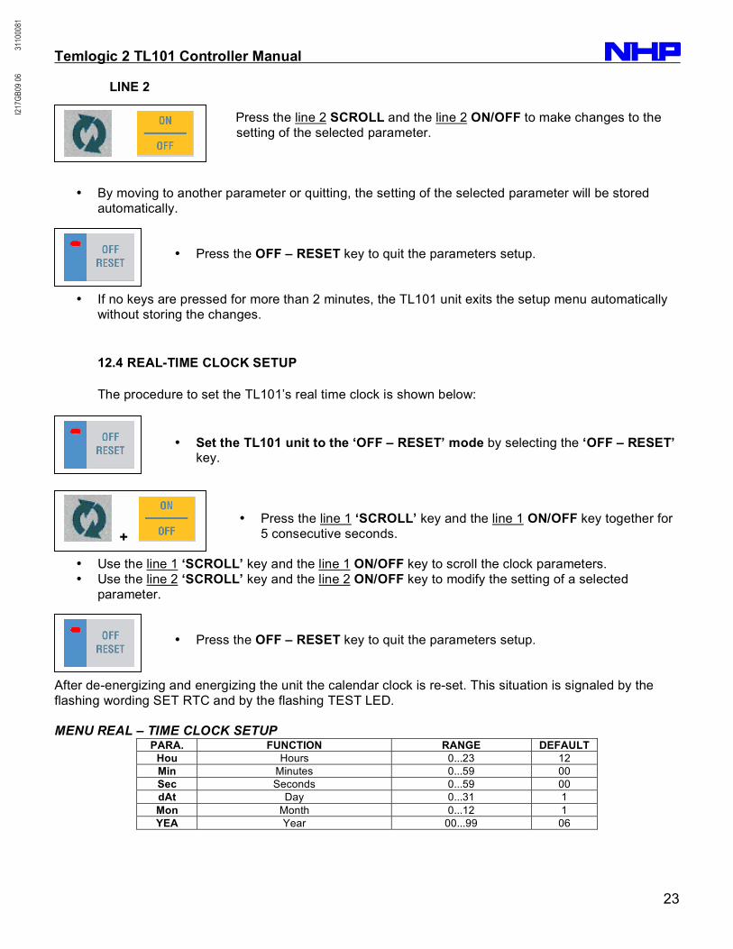
• Set the TL101 unit to the ‘OFF – RESET’ mode by selecting the ‘OFF – RESET’ key.
• Press the line 1 ‘SCROLL’ key and the line 1 ON/OFF key together for
5 consecutive seconds.
• Use the line 1 ‘SCROLL’ key and the line 1 ON/OFF key to scroll the clock parameters.
• Use the line 2 ‘SCROLL’ key and the line 2 ON/OFF key to modify the setting of a selected
parameter.
• Press the OFF – RESET key to quit the parameters setup.
After de-energizing and energizing the unit the calendar clock is re-set. This situation is signaled by the
flashing wording SET RTC and by the flashing TEST LED.
MENU REAL – TIME CLOCK SETUP PARA. FUNCTION RANGE DEFAULT
Hou Hours 0...23 12
Min Minutes 0...59 00
Sec Seconds 0...59 00
dAt Day 0...31 1
Mon Month 0...12 1
YEA Year 00...99 06
+
+
I217
GB09
06
3110
0081

Temlogic 2 TL101 Controller Manual
24
13.0 OUTPUT DATA / TESTS / REMOTE CONTROL
13.1 DISPLAY OF STATISTICAL DATA
The TL101 unit records a series of statistical data (operating times, operation counters, etc.) which are
stored in a retentive memory even when the unit is de-energised.
To access the statistical data follow the procedure below:
• Press the line 1 ‘SCROLL’ key and the line 2 ‘SCROLL’ key
together for 5 consecutive seconds starting from any operation mode.
• Each datum is shown by an acronym occupying both displays.
• To view the value of the corresponding datum the line 2 ‘SCROLL’ key. Both displays will show the numeric value of the 6-digit datum. After 3 seconds the acronym will be displayed again.
• For times shorter than 10000 hours, hours and minutes are displayed in the hhhh.mm format. Only
hours are displayed beyond this value.
• The different data variables available may be selected using the line 1 ‘SCROLL’ and the line 1 ‘ON/OFF’ key.
• Press the OFF – RESET key to exit the function. operating mode will not be changed.
• The operating times are identified by a cipher starting with letter t, while counters with C.
• A set of data may be cleared by pressing the line 1 ‘ON/OFF’ key for 5 seconds (CLEAR is displayed).
• All times or all counters will be cleared, depending on the position from where the clear operation is
performed.
+
I217
GB09
06
3110
0081

Temlogic 2 TL101 Controller Manual
25
The following table lists the statistical data available.
STATISTICAL DATA TABLE
DATUM
ACRONYM
DESCRIPTION
t.L1 Loa Total time for load connected to line 1 (line 1 circuit breaker closed)
t.L2 Loa Total time for load connected to line 2 (line 2 circuit breaker closed)
t.no Loa Total time for load disconnected from both lines (both circuit breakers open)
t.L1 PrE Total time for line 1 present (within limits)
t.L2 PrE Total time for line 2 present (within limits)
t.L1 AbS Total time for line 1 absent (off limits)
t.L2 AbS Total time for line 2 absent (off limits)
t.totAL Total time for TL101 operation
C.L1 Aut Count of number of operations (closing) -line 1 circuit breaker in automatic mode
C.L2 Aut Count of number of operations (closing) -line 2 circuit breaker in automatic mode
C.L1 Man Count of number of operations (closing) -line 1 circuit breaker in manual mode
C.L2 Man Count of number of operations (closing) -line 2 circuit breaker in manual mode
C.L1 Fau Count of number of failed operations - line 1 circuit breaker (alarm A03)
C.L2 FAu Count of number of failed operations - line 2 circuit breaker (alarm A04)
C.On OFF Count of total number of Tl101 energizing -de-energizing cycles
13.2 ALARMS
When an alarm event occurs, the TL101 either shows a code on the displays or lights up a dedicated LED.
• For non-retentive alarms, the indication disappears automatically when the alarm conditions stop,
while for retentive alarms a manual reset is needed from the unit front panel: this is done by pressing the OFF / RESET key (and then shifting to OFF mode).
• The presence of any alarm is signaled by the relevant flashing ALARM LED illuminating.
• In the presence of an alarm, both the global alarm output (ALA) and the TL101 ready output (rdy)
are de-energized. • An alarm can be disabled by programming to OFF the parameter defining its threshold or the
programmable input generating it.
• The following table lists the possible alarms and their meanings. The RET column specifies if the alarm is retentive, while the MODE column indicates the operating modes (OFF - MANUAL - AUTO
- TEST) where the alarm is enabled.
ALARM CODE TABLE
CODE DESCRIPTION RET MODE
A01 Battery voltage too low O M A T
A02 Battery voltage too high O M A T
A03 Line 1 circuit breaker timeout A T
A04 Line 2 circuit breaker timeout A T
A05 Line 1 wrong phase sequence O M A T
A06 Line 2 wrong phase sequence O M A T
A07 Load not powered timeout A T
A08 Generator not available O M A T
A09 Emergency O M A T
LED Withdrawn Line 1 / 2 circuit breaker withdrawn A T
LED Trip Line 1/ 2 circuit breaker protection intervention A T
I217
GB09
06
3110
0081

Temlogic 2 TL101 Controller Manual
26
A01 - A02 - Battery voltage beyond threshold for a time exceeding the time set. A03 - A04 - The changeover device did not perform the opening or closing operation within the maximumtime set. After alarm tripping, the opening or closing command is inhibited. If motorised circuit breakers areused, alarms are tripped only if at least one of the two power sources is present, i.e. if it is higher than theminimum thresholds programmed.A05 - A06 - The phase sequence recorded does not correspond to the one programmed. A07 - The load remained de-energized for a time exceeding the one programmed by P2.11, either because supply lines were not available or because both circuit breakers remained open. A08 - Can be generated by the opening of the external ‘generator not ready’ input or when, after having started the generator, the voltage does not become acceptable within the time specified by P2.11. If the alarm is generated by the external input then it is not retentive. Otherwise it is retentive and thus must be re-set using RESET/OFF key. In applications with two generators, A08 is shown on the Line 1 or Line 2 display depending on which generator generated the alarm. A09 - Alarm generated by the opening of the external emergency input. Both circuit breakers are opened. LED WITHDRAWN - Generated by the opening of programmable input Withdrawn. The open and close commands of the circuit breaker concerned are inhibited. LED TRIP - Generated by the closing of programmable input Trip. The open and close commands of the circuit breaker concerned are inhibited.
13.3 AUTOMATIC TEST
The Automatic test consists of a generator starting cycle that is executed periodically to check the efficiency of the generator itself, when TL101 is in AUTO mode.
• � The frequency and the duration of the automatic test can be defined by the user. See setup menu P8 for a more detailed description of all parameters involved in automatic test programming.
�• The dedicated LED TEST indicates that the automatic test is enabled. It can be activated or disabled by parameter P8.01 or directly from the front panel (without entering setup programming) by pushing line 2 SCROLL key and then operation mode TEST key . This operation does not change the TL101 operating mode. 13.4 DIAGNOSTIC MESSAGE
The TL101 display can show messages to signal the implementation of a function or a particular situation.
• � By pressing one of the keys for measure selection, the diagnostic display is temporarily stopped to allow to view the measure.
CODE DESCRIPTION StA
Generator set startup
Coo
Generator set cooling cycle
FSi
Line failure simulation
—-
Interlock time in progress
toL
Test with load in progress
Set rtc
Calendar clock setup needed (see P2.23)
Loc
Locked keypad
Unl
Unlocked keypad
I217
GB09
06
3110
0081

Temlogic 2 TL101 Controller Manual
27
13.5 KEYPAD LOCK
The TL101 keypad can be locked either by means of a programmable input or with a particular procedure
from front keys.
• Once the keypad is locked, it will only be possible to view measures, but not to change operating
mode or to operate manually on circuit breakers. Only the keys for measure selection will remain
enabled. • Any attempt to use the locked keys will cause the word Loc to be displayed.
• To lock or unlock the keypad, press the line 1 SCROLL key and, while holding it down, press the
line 2 SCROLL key three times without releasing it at the end. • Release then the line 1 SCROLL key and then press it 5 times, then release both keys.
• When the keypad is locked, the display shows the word Loc. Conversely it has been unlocked, the
word UnL would appear.
13.6 REMOTE CONTROL
It is possible to connect TL101 to a PC through its serial interface and to monitor the operation of the
device using a generic SCADA software that supports Modbus protocol.
• TL101 can be connected directly in peer-to-peer configuration using the RS232 serial interface port and cable. NOTE RS485 is a non standard interface.
Fig.1: Controller rear terminal connections
I217
GB09
06
3110
0081

Temlogic 2 TL101 Controller Manual
28
14.0 MECHANICAL DIMENSIONS & CUT-OUTS
Fig.2: Controller dimensions & panel cut-out
15.0 WIRING DIAGRAMS
Fig.3: Motorised circuit breaker control
I217
GB09
06
3110
0081

Temlogic 2 TL101 Controller Manual
29
Fig.4: Motorised changeover switch control
Fi g. 5 : Contactor control
Cnt
I217
GB09
06
3110
0081

Temlogic 2 TL101 Controller Manual
30
Fig.6: RS485 Interface wiring
I217
GB09
06
3110
0081