Technical Manual, NBT External Wall Insulation Render System · NBT Masonry Render Systems The...
24
Technical Manual, NBT External Wall Insulation Render System
Transcript of Technical Manual, NBT External Wall Insulation Render System · NBT Masonry Render Systems The...
Technical Manual, NBT External Wall Insulation
Render System
Natural Building Technologies LtdThe Hangar, Worminghall Road, Oakley, Buckinghamshire. HP18 9UL
T: 01844 338338 F: 01844 [email protected] www.natural-building.co.uk2
Content Description of Timber Frame Systems 2 Performance Guide 3 Airtightness 4 Summer Overheating 5
NBT Timber Frame Render Sys-tem System Build up 6 Physical Properties 7 Key Considerations - Designers 8 Key Considerations - Installers 9 Installation Procedures 10 Detail Solutions 13 Components & Accessories 14 Detail Drawings NBT DIFFUTHERM 18 NBT Product Overview: Insulation 23
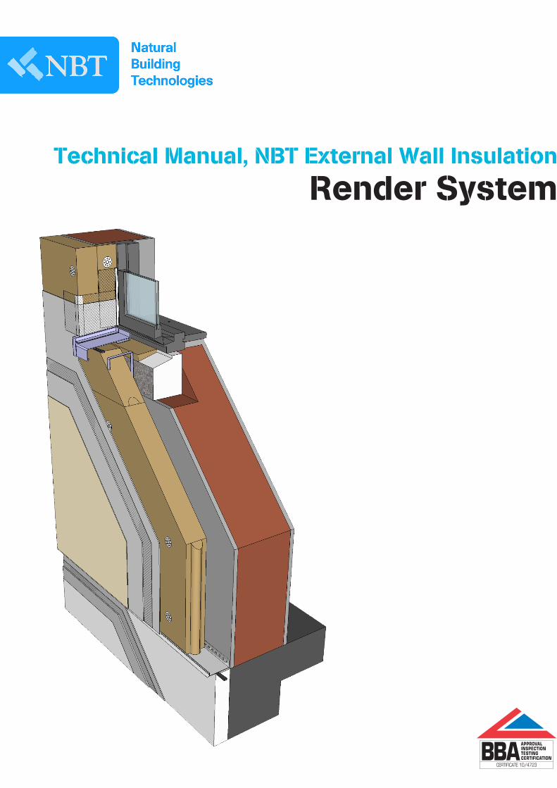
NBT Masonry Render SystemsThe building system is a masonry structure insulated externally with woodfibre (Diffutherm) and finished with render.
Made from over 95 % waste softwood and under 5 % inert water-proofing additives, NBT PAVATEX DIFFUTHERM, are a genuinely sustainable non-toxic building material. To produce NBT PAVATEX boards, waste wood fibres are pulped and mixed with water. The pulp is heated to activate the natural lignin they contain in order to glue the fibres together. The pulp is then pressed into boards, dried, and cut to size.
The advanced manufacturing process uses the inherent properties of wood fibres to produce boards with many excellent technical qualities for thermal and acoustic insulation, thermal storage capacity, vapour permeability and moisture control.
No limits to architectual design: NBT CLAD System and NBT EWI RENDER System facades interact togethew
NBT MASONRY EWI - RenderIntroduction
For more information please visit www.natural-building.co.uk
3
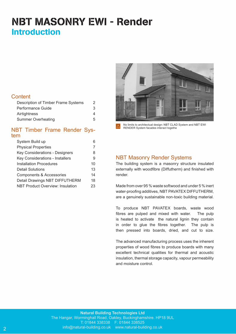
Performance GuideA modern wall insulation system must do more than just protect building occupants from cold. It must cre-ate a comfortable and healthy environment in all pos-sible combinations of external and internal conditions and control the effects of external heat, cold, noise and internal moisture generation.
NBT Building Systems Keep the building warm for longer in cold weather:Low thermal conductivity and high vapour permeability provide high thermal insulation with no risk of intersti-tial condensation. Vapour barriers are unnecessary. Woodfibre boards reduce the effect of thermal bridging and the interlocking board design easily achieves good windtightness, so increasing thermal performance. En-ergy use for heating is significantly reduced leading to lower CO2 emissions and running costs.
Keep the building quieter:The high mass and the fibrous texture of NBT PAVATEX woodfibre boards give excellent acoustic performance to buildings.
Keep the building cooler in hot weather:The unique combination of high density, high specific heat capacity and low thermal conductivity gives Exter-nal Wall Insulation (EWI) solutions the effect of thermal mass that would normally be associated with render onto masonry. Compared to conventional EWI material the risk of condensation behind the render during cold nights is minimized as the boards will store the day’s heat.
Keep the building dry and breathable:NBT PAVATEX woodfibre boards are very vapour per-meable and hygroscopic. This allows them to disperse accumulating short term moisture and protect vulner-able elements of the building fabric, with no reduction in the performance of the boards themselves. The boards allow moisture from within the structure to pass easily to the outside. This provides a safeguard against high moisture content. This is vital for the long-term health of the building fabric, and is completely overlooked by most conventional insulation systems.
NBT Natural Insulation Products for:
Simple and robustImproved heat storage
Excellent sound insulationHighly vapour permeable constructions that do
not need membranes to control interstitial condensationSubstantial saving of build cost compared with
conventional timber frame constructionSimple robust construction has few skilled operations
and is easily adapted for off site manufactureReduced thermal bridging - ideal to achieve
high standard and beyond
NBT MASONRY EWI - RenderIntroduction
Natural Building Technologies LtdThe Hangar, Worminghall Road, Oakley, Buckinghamshire. HP18 9UL
T: 01844 338338 F: 01844 [email protected] www.natural-building.co.uk4
Principle
A building envelope should be airtight when all ventilation openings are closed. The design requirement for air changes has to be provided by opening the windows manually, other controllable ventilation openings or suitable mechanical ventilation systems.
When assessing the air permeability of the building envelope, the following aspects must be considered separately:
• Individual building components must exhibit the necessary airtightness in accordance with building component standards
• The overall air permeability of the building envelope must meet the limiting and target values of building regulations
• Local air permeability (leaks, primarily on the inside) can lead to moisture damage because they allow moist interior air to infi ltrate the construction
• Local air permeability and associated draughts can have a detrimental effect on the thermal comfort of the occupants and can also lead to increased energy consumption
Air permeability
The air permeability of the building envelope is specifi ed by the ratio of surface area of the building to the hourly air exchange rate for a 50 Pa pressure difference. In Part L Building Regulations an air permeability of 10.0 m3/m2/h is allowed, for EST best practice for CSH level 3 an air permeability of 3.0 m3/m2/h, for higher CSH levels an air permeability of 1.0 m3/m2/h and for PASSIVHAUS an air permeability of 0.6 m3/m2/h are accepted as the maximum.
Design and construction
To ensure that the building envelope has the necessary degreee of airtightness, an airtightness layer is required over all parts of the construction on the warm side of the thermal insulation. Generally, the vapour control layer and airtight layer funtions are combined and provided by one membrane, sheeting or a board type material (OSB, multi-ply board, plywood, gypsum fi breboard, etc.). Such materials require fi xings and permanent air tight seals at joints and junctions in the form of adhesive tape, glue, mechanical fasteners etc., or may need to be held in place with battens.
Rock wool and glass-fi bre boards, wood fi breboards, wooden panelling, planking, acoustic linings, building papers etc. cannot achieve the degree of airtightness required for modern buildings.
The airtightness layer must be conceived at the design stage as a “seamless” layer over the entire building envelope, planned with its practical installation in mind, and shown as a separate layer on all drawings. Good planning includes
cor responding information in the tender docu-ments and detail in the working and fabrication drawings. The materials used to achieve the air-tightness must be sealed air-tight at junctions with adjoining elements such as windows, doors
and foundations. The installation of several layers each of which are only partially airtight will not result in a building with an adequate degree of sealing.
Testing
In order to achieve an airtight building envelope, measures and checks during construction and after completion of the building are necessary. If the airtightness layer has been properly designed and planned, expensive blower door measurements, leak detection by means of smoke tests or IR thermography, and unnecessary costs of repairs can be saved.
A properly designed and constructed building will fulfi l airtightness requirements without the need for further special work. NBT systems provide proper design and site support to ensure that the correct levels of airtightness are achieved.
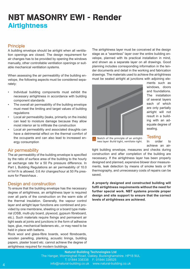
w Sketch of the principle of an airtight-ness layer: Build tight, ventilate right.
Airtightness
PrincipleA building envelope should be airtight when all ventila-tion openings are closed. The design requirement for air changes has to be provided by opening the windows manually, other controllable ventilation openings or suit-able mechanical ventilation systems.
When assessing the air permeability of the building en-velope, the following aspects must be considered sepa-rately:
• Individual building components must exhibit the necessary airtightness in accordance with building component standards
• The overall air permeability of the building envelope must meet the limiting and target values of building regulations
• Local air permeability (leaks, primarily on the inside) can lead to moisture damage because they allow moist interior air to infiltrate the construction
• Local air permeability and associated draughts can have a detrimental effect on the thermal comfort of the occupants and can also lead to increased en-ergy consumption
Air permeabilityThe air permeability of the building envelope is specified by the ratio of surface area of the building to the hourly air exchange rate for a 50 Pa pressure difference. In Part L Building Regulations an air permeability of 10.0 m3/m2/h is allowed. 0.6 Air changes/hour at 50 Pa pres-sure for Passivhaus .
Design and constructionTo ensure that the building envelope has the necessary degree of airtightness, an airtightness layer is required over all parts of the construction on the warm side of the thermal insulation. Generally, the vapour control layer and airtight layer functions are combined and pro-vided by one membrane, sheeting or a board type mate-rial (OSB, multi-ply board, plywood, gypsum fibreboard, etc.). Such materials require fixings and permanent air tight seals at joints and junctions in the form of adhesive tape, glue, mechanical fasteners etc., or may need to be held in place with battens. Rock wool and glass-fibre boards, wood fibreboards, wooden panelling, planking, acoustic linings, building papers, plaster board etc. cannot achieve the degree of airtightness required for modern buildings.
The airtightness layer must be conceived at the design stage as a “seamless” layer over the entire building en-velope, planned with its practical installation in mind, and shown as a separate layer on all drawings. Good planning includes corresponding information in the ten-der documents and detail in the working and fabrication drawings. The materials used to achieve the airtightness must be sealed airtight at junctions with adjoining ele-
ments such as windows, doors and foundations. The installation of several layers each of which are only partially airtight will not result in a build-ing with an ad-equate degree of sealing.
TestingIn order to achieve an air-
tight building envelope, measures and checks during construction and after completion of the building are necessary. If the airtightness layer has been properly designed and planned, expensive blower door measure-ments, leak detection by means of smoke tests or IR thermography, and unnecessary costs of repairs can be saved.
A properly designed and constructed building will fulfil airtightness requirements without the need for further special work. NBT systems provide proper design and site support to ensure that the correct levels of airtightness are achieved.
NBT MASONRY EWI - Render Airtightness

For more information please visit www.natural-building.co.uk
5
Selecting the right insulationAs part of a building’s design it is important to consider the effects of summer overheating control, particulary when there are rooms in roofs or where the construction system is lightweight such as steel or timber frame.
Summer overheating is caused by any or a combination of three reasons:
• too great internal gains from appliances, people, machines etc.
• too much sun directly through windows due to poor summer shading
• heat passing directly through the walls
The solution to the fi rst is to reduce the gains or ventilate, the second requires better shading, and the third is solved by reducing peak heat gain to the room by changing the decrement delay and factor.
Decrement delay and factor can be thought of as the amount a peak external surface temperature is
smoothed out by the structure, and the time that the peak is delayed before it reaches the inside.
To reduce the solar heat passing through a roof or a wall, a low decrement factor is needed, and more importantly, it should delay the passage of heat by between 6 - 12 hours after the external solar radiation peak – this means that the decrement delay of a wall or roof construction should be between 6 - 12 hours.
In terms of achieving these satisfactory values, an insulation material that has a high thermal mass is needed to produce better values. A combination of density, thermal conductivity and specifi c heat capacity is required.
NBT PAVATEX woodfi bre boards have an excellent
Summer Overheating
combination of low λD (k-value) (0.038 - 0.047 W/m²K), high specifi c heat capacity (2100J/kgK) and for insulation boards a high density (140 - 240 kg/m³). These values far exceed any conventional insulation material. This means that with NBT PAVATEX woodfi bre insulation a roof or “lightweight” structure such as lightweight frame building can perform as though it was a much more massive structure.
The consequence is the reduction of internal temperatures by 4° C or more in summer compared to a room which may have the same U-value but conventional insulation.
15
55
20
25
30
35
40
45
50
10
Tem
pera
ture
°C
6h 9h 12h 15h 18h 21h 24h 3h 6h
Temperature on the inside surface
Temperature on the external surface of the wall
Decrement delay (time lag)
Exte
rnal
am
plitu
de
Internal amplitude
Day 1 Day 2
Selecting the right insulationAs part of a building’s design it is important to consider the effects of summer overheating con-trol, particularly when there are rooms in roofs or where the construction system is lightweight such as steel or timber frame.
Summer overheating is caused by any or a combination of three reasons:• high internal gains from appliances, people, ma-
chines etc.• high solar gain through windows due to poor sum-
mer shading• heat passing directly through the walls
The solution to the first is to reduce the gains or venti-late, the second requires better shading, and the third is solved by reducing peak heat gain to the room by changing the decrement delay and factor.
Decrement delay and factor can be thought of as the amount a peak external surface temperature is smoothed out by the structure, and the time that the peak is delayed before it reaches the inside.
To reduce the solar heat passing through a roof or a wall, a low decrement factor is needed, and more impor-tantly, it should delay the passage of heat by between
6 - 12 hours after the external solar radiation peak – this means that the decrement delay of a wall or roof con-struction should be between 6 - 12 hours.
In terms of achieving these satisfactory values, an insu-lation material that has a high thermal mass is needed to produce better values. A combination of density, ther-mal conductivity and specific heat capacity is required.
NBT PAVATEX woodfibre boards have an excellent combination of low λ (k-value) (0.038 - 0.047 W/m²K), high specific heat capacity (2100J/kgK) and for insu-lation boards a high density (140 - 240 kg/m³). These values far exceed any conventional insulation mate-rial. This means that with NBT PAVATEX woodfibre insulation a roof or “lightweight” structure such as lightweight frame building can perform as though it was a much more massive structure.
The consequence is the reduction of internal tempera-tures by 4° C or more in summer compared to a room which may have the same U-value but conventional in-sulation.
NBT MASONRY EWI - RenderSummer Overheating
Natural Building Technologies LtdThe Hangar, Worminghall Road, Oakley, Buckinghamshire. HP18 9UL
T: 01844 338338 F: 01844 [email protected] www.natural-building.co.uk6
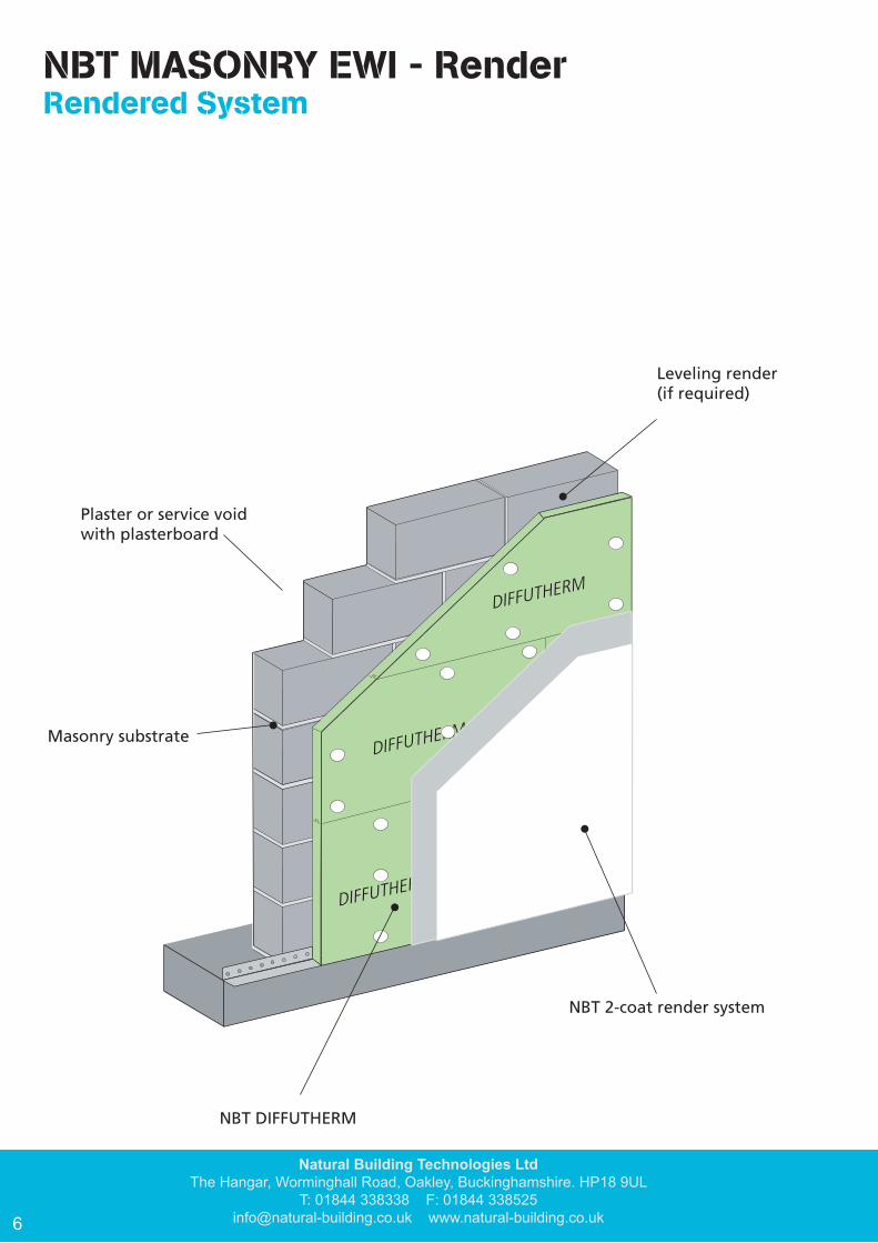
NBT MASONRY EWI - RenderRendered System
DIFFUTHERM
DIFFUTHERM
DIFFUTHERM
Leveling render(if required)
Plaster or service voidwith plasterboard
Masonry substrate
NBT DIFFUTHERM
NBT 2-coat render system
For more information please visit www.natural-building.co.uk
7
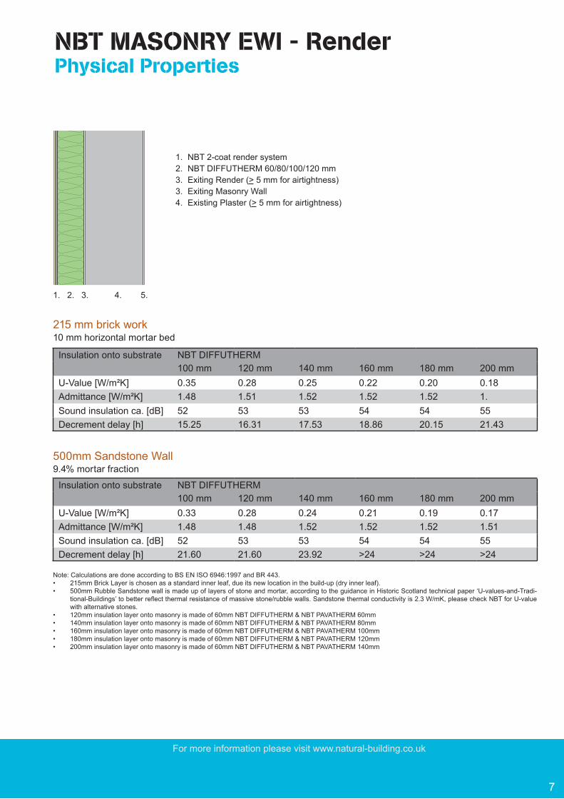
NBT MASONRY EWI - Render Physical Properties
Note: Calculations are done according to BS EN ISO 6946:1997 and BR 443. • 215mm Brick Layer is chosen as a standard inner leaf, due its new location in the build-up (dry inner leaf).• 500mm Rubble Sandstone wall is made up of layers of stone and mortar, according to the guidance in Historic Scotland technical paper ‘U-values-and-Tradi-
tional-Buildings’ to better reflect thermal resistance of massive stone/rubble walls. Sandstone thermal conductivity is 2.3 W/mK, please check NBT for U-value with alternative stones.
• 120mm insulation layer onto masonry is made of 60mm NBT DIFFUTHERM & NBT PAVATHERM 60mm• 140mm insulation layer onto masonry is made of 60mm NBT DIFFUTHERM & NBT PAVATHERM 80mm• 160mm insulation layer onto masonry is made of 60mm NBT DIFFUTHERM & NBT PAVATHERM 100mm• 180mm insulation layer onto masonry is made of 60mm NBT DIFFUTHERM & NBT PAVATHERM 120mm• 200mm insulation layer onto masonry is made of 60mm NBT DIFFUTHERM & NBT PAVATHERM 140mm
Insulation onto substrate NBT DIFFUTHERM100 mm 120 mm 140 mm 160 mm 180 mm 200 mm
U-Value [W/m²K] 0.35 0.28 0.25 0.22 0.20 0.18Admittance [W/m²K] 1.48 1.51 1.52 1.52 1.52 1.Sound insulation ca. [dB] 52 53 53 54 54 55Decrement delay [h] 15.25 16.31 17.53 18.86 20.15 21.43
215 mm brick work10 mm horizontal mortar bed
Insulation onto substrate NBT DIFFUTHERM100 mm 120 mm 140 mm 160 mm 180 mm 200 mm
U-Value [W/m²K] 0.33 0.28 0.24 0.21 0.19 0.17Admittance [W/m²K] 1.48 1.48 1.52 1.52 1.52 1.51Sound insulation ca. [dB] 52 53 53 54 54 55Decrement delay [h] 21.60 21.60 23.92 >24 >24 >24
500mm Sandstone Wall9.4% mortar fraction
1. NBT 2-coat render system2. NBT DIFFUTHERM 60/80/100/120 mm3. Exiting Render (> 5 mm for airtightness)3. Exiting Masonry Wall 4. Existing Plaster (> 5 mm for airtightness)
1. 2. 3. 4. 5.
Natural Building Technologies LtdThe Hangar, Worminghall Road, Oakley, Buckinghamshire. HP18 9UL
T: 01844 338338 F: 01844 [email protected] www.natural-building.co.uk8
General: Provide the contractor with full and complete details for all critical areas of the system including those listed below. Leave nothing to be agreed “on-site“.
System Guarantee: The NBT EWI RENDER system is guaranteed only if boards, mortars, renders and accessories approved by NBT are used. NBT DIFFUTHERM has LABC (Local Authority Building Control) approval and BBA (British Board of Agreement) approval (BBA CERTIFICATE No 10/4723).
The NBT MASONRY RENDER system is certified for use in rain exposure zones (EZ) 1- 4
DPC-Level: Do not use NBT DIFFUTHERM boards below DPC level. Use boards suitable for wet exposure (EPS, XPS) and a different NBT base coat (HM 50) in the plinth area (i.e. within 300 mm of ground level).
Building Height: The NBT EWI RENDER system is for use in buildings where the height to the top floor is < 18 m. If intended for use in higher buildings, contact NBT for advice.
Non Load Bearing: The NBT EWI RENDER system must be designed so that no loads from the structure are carried by the boards or render. Only lightweight fittings can be attached directly to the NBT DIFFUTHERM boards. Carefully plan the location of down-pipes, lights, security systems etc.
Movement Joints: Movement joints in the substrate must be incorporated into the NBT EWI RENDER system. Consider render only movement joints for walls > 18 m.
Weather Tightness: For weather tightness seal the boards against the structure at all joints, intersections, openings and penetrations and along all edges using ISO-BLOCO expanding sealing tape. For weather tightness, seal the render around all openings (door/window) using the appropriate APU rail (Frame seal bead).
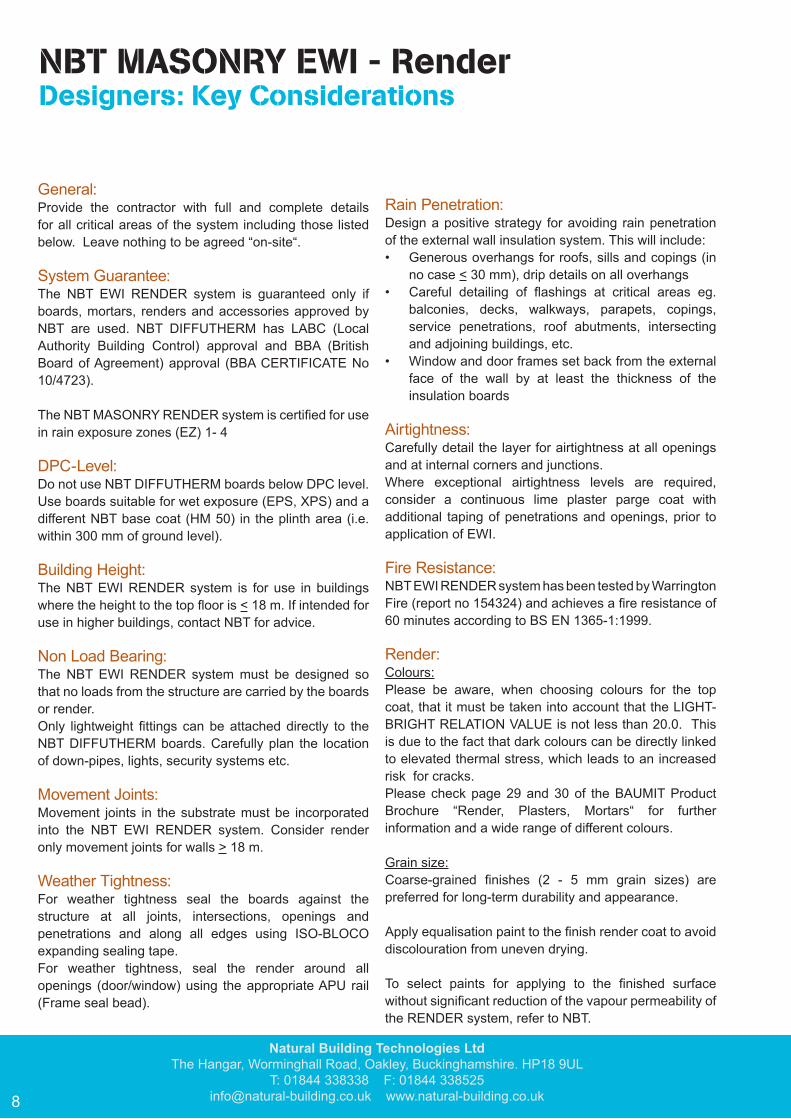
Rain Penetration: Design a positive strategy for avoiding rain penetration of the external wall insulation system. This will include:• Generous overhangs for roofs, sills and copings (in
no case < 30 mm), drip details on all overhangs• Careful detailing of flashings at critical areas eg.
balconies, decks, walkways, parapets, copings, service penetrations, roof abutments, intersecting and adjoining buildings, etc.
• Window and door frames set back from the external face of the wall by at least the thickness of the insulation boards
Airtightness: Carefully detail the layer for airtightness at all openings and at internal corners and junctions.Where exceptional airtightness levels are required, consider a continuous lime plaster parge coat with additional taping of penetrations and openings, prior to application of EWI.
Fire Resistance: NBT EWI RENDER system has been tested by Warrington Fire (report no 154324) and achieves a fire resistance of 60 minutes according to BS EN 1365-1:1999.
Render: Colours:Please be aware, when choosing colours for the top coat, that it must be taken into account that the LIGHT-BRIGHT RELATION VALUE is not less than 20.0. This is due to the fact that dark colours can be directly linked to elevated thermal stress, which leads to an increased risk for cracks.Please check page 29 and 30 of the BAUMIT Product Brochure “Render, Plasters, Mortars“ for further information and a wide range of different colours.
Grain size:Coarse-grained finishes (2 - 5 mm grain sizes) are preferred for long-term durability and appearance.
Apply equalisation paint to the finish render coat to avoid discolouration from uneven drying. To select paints for applying to the finished surface without significant reduction of the vapour permeability of the RENDER system, refer to NBT.
NBT MASONRY EWI - Render Designers: Key Considerations

For more information please visit www.natural-building.co.uk
9
General: The NBT EWI RENDER system must only be installed by approved contractors who have been trained by NBT.
The details and specifications in this guide and from the and from the designer should be followed as the basis of a successful installation.
The system is guaranteed if only boards, mortars, renders and accessories approved by NBT are used.
Movement joints in the substrate must be incorporated into the NBT EWI RENDER system.
Only lightweight fittings can be attached directly to the NBT DIFFUTHERM boards. Carefully plan the location of down-pipes, lights, security systems etc.
Boards: Plan board layout to reduce wastage prior to commencing installation.
A base rail must be used to start the system.
Minimum bond overlap is 200 mm between courses.
Boards must not be wet or damaged and board edges must be tightly butted together.
Tightly fill all gaps with woodfibre.
For weather tightness seal the boards against the structure at all joints, intersections, openings and penetrations and along all edges.
Do not use the NBT EWI RENDER system below DPC level. Use appropriate boards (XPS) and a different NBT base coat (HM 50) in the plinth area (i.e. within 300 mm above ground level).
Do not allow the boards to stand exposed to weather for more than 60 days after fixing before applying the render system.
Renders: Do not apply the render system onto rain-soaked boards or when the air temperature is below 5o C and avoid working in strong, direct sunlight.
The reinforcing mesh should lie in the outer 1/3 of the base coat layer and sheets should overlap by at least 100 mm.
Additional mesh reinforcement is required around all openings, along all corners and edges, across zones where suspended floors intersect walls and where boards are applied over different substrates, along continuous straight board joints and over repaired areas.
Seal the render around all openings using the appropriate APU rail (Window Frame Sealing Bead).
Allow 1 day per 1 mm thickness drying time for the base coat before applying the topcoat.
Apply equalisation paint to the finish render coat to avoid discolouration from uneven drying. This is not required where the top coat is Silica, Silicon or Nanopor top coat render is used.
For premixed Top coat apply DG27 primer for suction and key.
NBT MASONRY EWI - Render Installers: Key Considerations
Natural Building Technologies LtdThe Hangar, Worminghall Road, Oakley, Buckinghamshire. HP18 9UL
T: 01844 338338 F: 01844 [email protected] www.natural-building.co.uk10
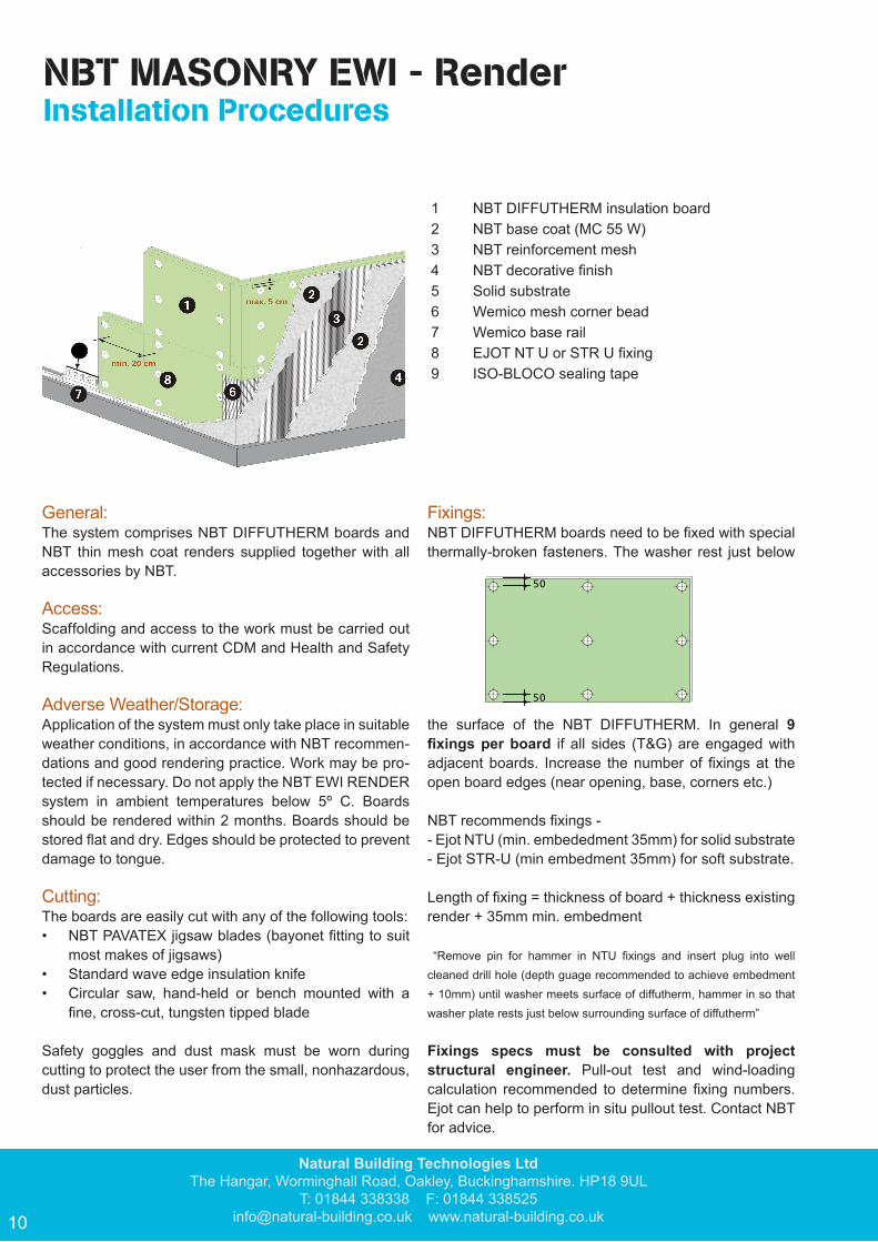
General: The system comprises NBT DIFFUTHERM boards and NBT thin mesh coat renders supplied together with all accessories by NBT.
Access: Scaffolding and access to the work must be carried out in accordance with current CDM and Health and Safety Regulations.
Adverse Weather/Storage:Application of the system must only take place in suitable weather conditions, in accordance with NBT recommen-dations and good rendering practice. Work may be pro-tected if necessary. Do not apply the NBT EWI RENDER system in ambient temperatures below 5º C. Boards should be rendered within 2 months. Boards should be stored flat and dry. Edges should be protected to prevent damage to tongue.
Cutting: The boards are easily cut with any of the following tools:• NBT PAVATEX jigsaw blades (bayonet fitting to suit
most makes of jigsaws)• Standard wave edge insulation knife• Circular saw, hand-held or bench mounted with a
fine, cross-cut, tungsten tipped blade
Safety goggles and dust mask must be worn during cutting to protect the user from the small, nonhazardous, dust particles.
Fixings: NBT DIFFUTHERM boards need to be fixed with special thermally-broken fasteners. The washer rest just below
the surface of the NBT DIFFUTHERM. In general 9 fixings per board if all sides (T&G) are engaged with adjacent boards. Increase the number of fixings at the open board edges (near opening, base, corners etc.)
NBT recommends fixings - - Ejot NTU (min. embededment 35mm) for solid substrate - Ejot STR-U (min embedment 35mm) for soft substrate.
Length of fixing = thickness of board + thickness existing render + 35mm min. embedment
“Remove pin for hammer in NTU fixings and insert plug into well cleaned drill hole (depth guage recommended to achieve embedment + 10mm) until washer meets surface of diffutherm, hammer in so that washer plate rests just below surrounding surface of diffutherm”
Fixings specs must be consulted with project structural engineer. Pull-out test and wind-loading calculation recommended to determine fixing numbers. Ejot can help to perform in situ pullout test. Contact NBT for advice.
1 NBT DIFFUTHERM insulation board2 NBT base coat (MC 55 W)3 NBT reinforcement mesh4 NBT decorative finish5 Solid substrate6 Wemico mesh corner bead7 Wemico base rail8 EJOT NT U or STR U fixing9 ISO-BLOCO sealing tape
NBT MASONRY EWI - Render Installation Procedures
50
50
For more information please visit www.natural-building.co.uk
11
Board System: Below the DPC and in the plinth area (up to 300 mm above finished ground level) use XPS plinth boards; above the plinth area use NBT DIFFUTHERM boards
Fitting: Above plinth area: Fix the base rail and corner rail above DPC to substrate, using 2 fixing per meter. Rail connector clips may be fitted at all rail joints. Attach clip-on drip profile to complete run of base and corner rail.
Locate the 1st course of NBT DIFFUTHERM boards tightly in the base rail channel with grooved side down and edge tongue and groove joints fully engaged. Fix through the boards into the substrate using recommended number of fixings per board. Increase fixings at the edges. The faces of the boards should be flush. Install 2nd course in ½ bond pattern, over-lapping board ends at vertical corners, ensuring all board joints are fully engaged and tightly packed. Fix to substrate as for 1st course. Increase fixings at the corner.
Fill any gaps and areas of damaged boards with loose woodfibres and apply a “patch” of reinforcing mesh at least 200 mm larger than area of damage/repair.
Openings and Abutments: At all openings, service penetrations and free edges, seal the board to the structure/service substrate using ISO-BLOCO sealing tape to create a weather tight joint.
Reveals: Fully paste the rear side of the reveal boards using NBT base coat and trowel through using a tooth trowel. Apply a ISO-BLOCO sealing tape along the edge of the board and place the board tightly up against the window or door frame. if required use reveal fixings (Ejot DDA)
Render System: Apply APU rails to all door and window frames to form a weather tight joint.
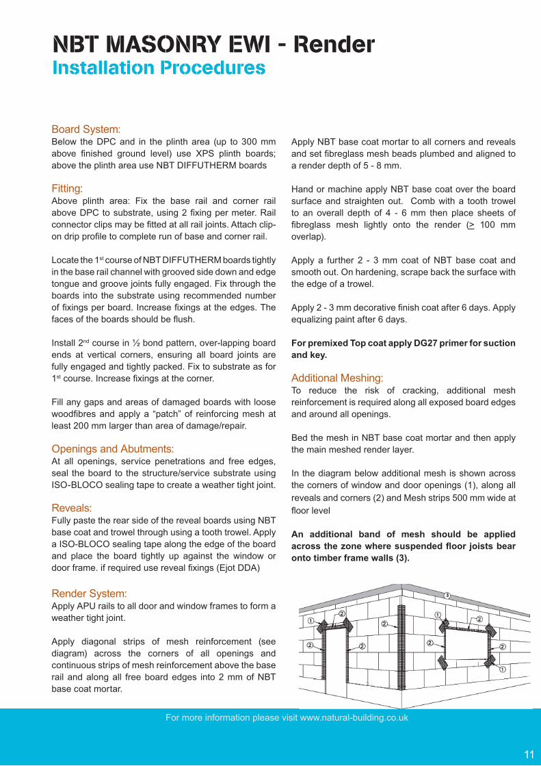
Apply diagonal strips of mesh reinforcement (see diagram) across the corners of all openings and continuous strips of mesh reinforcement above the base rail and along all free board edges into 2 mm of NBT base coat mortar.
Apply NBT base coat mortar to all corners and reveals and set fibreglass mesh beads plumbed and aligned to a render depth of 5 - 8 mm.
Hand or machine apply NBT base coat over the board surface and straighten out. Comb with a tooth trowel to an overall depth of 4 - 6 mm then place sheets of fibreglass mesh lightly onto the render (> 100 mm overlap).
Apply a further 2 - 3 mm coat of NBT base coat and smooth out. On hardening, scrape back the surface with the edge of a trowel.
Apply 2 - 3 mm decorative finish coat after 6 days. Apply equalizing paint after 6 days.
For premixed Top coat apply DG27 primer for suction and key.
Additional Meshing: To reduce the risk of cracking, additional mesh reinforcement is required along all exposed board edges and around all openings.
Bed the mesh in NBT base coat mortar and then apply the main meshed render layer.
In the diagram below additional mesh is shown across the corners of window and door openings (1), along all reveals and corners (2) and Mesh strips 500 mm wide at floor level
An additional band of mesh should be applied across the zone where suspended floor joists bear onto timber frame walls (3).
NBT MASONRY EWI - Render Installation Procedures

Natural Building Technologies LtdThe Hangar, Worminghall Road, Oakley, Buckinghamshire. HP18 9UL
T: 01844 338338 F: 01844 [email protected] www.natural-building.co.uk12
System Movement Beads: Where structural movement joints or change in substrate occur a system movement bead should be incorporated into the NBT EWI RENDER system to prevent cracking due to differential movement. NBT recommends Wemico PVC system movement bead.
Render Movement Beads: Render movement joints in the substrate must be incorporated into the NBT EWI RENDER system every 18m on a continuos horizontal span.
ISO-BLOCO sealing tape: For weather tightness seal the boards against the structure at all joints, intersections, openings and penetrations and along all edges using ISO-BLOCO sealing tape. Such areas include window and door frames, sills, eaves and soffit boards. ISO-BLOCO is also recommended around service penetration into the Diffutherm.
System Stop or Butting to other substrate: Where boards butt up to other substrates or need a stop (Mid terrace), use system stop profile at the edge of Diffutherm. Seal the junction by ISO-BLOCO sandwiched between the substrate and the stop profile.
NBT MASONRY EWI - Render Installation Procedures
For more information please visit www.natural-building.co.uk
13
NBT DIFFUTHERM – Detail Solutions
Board Pattern:
NOTE:PLEASE FIND DETAIL DRAWINGS AT THE END OF THIS MANUAL
Set out NBT DIFFUTHERM boards so that board edges DO NOT coincide with the corners of wall openings.
Always ensure that the vertical joints are staggered by at least 200 mm between courses and that each board is supported on at least two studs.
NBT DIFFUTHERM board joints DO NOT have to terminate on a stud due to the tongue groove board edge.
2
1133
Key to Details1 Edges:• Weather tightness with use of ISO-BLOCO sealing tape
2 Plinth:• Plinth area 300 mm• Use plinth & perimeter insulation board (XPS) in plinth area• Use base rail at bottom of NBT DIFFUTHERM
3 Window and door:• Weather tightness with use of ISO-BLOCO sealing tape and APU-rails• Use window sills with upstands• NBT DIFFUTHERM board pattern to window and door opening (see below)
26
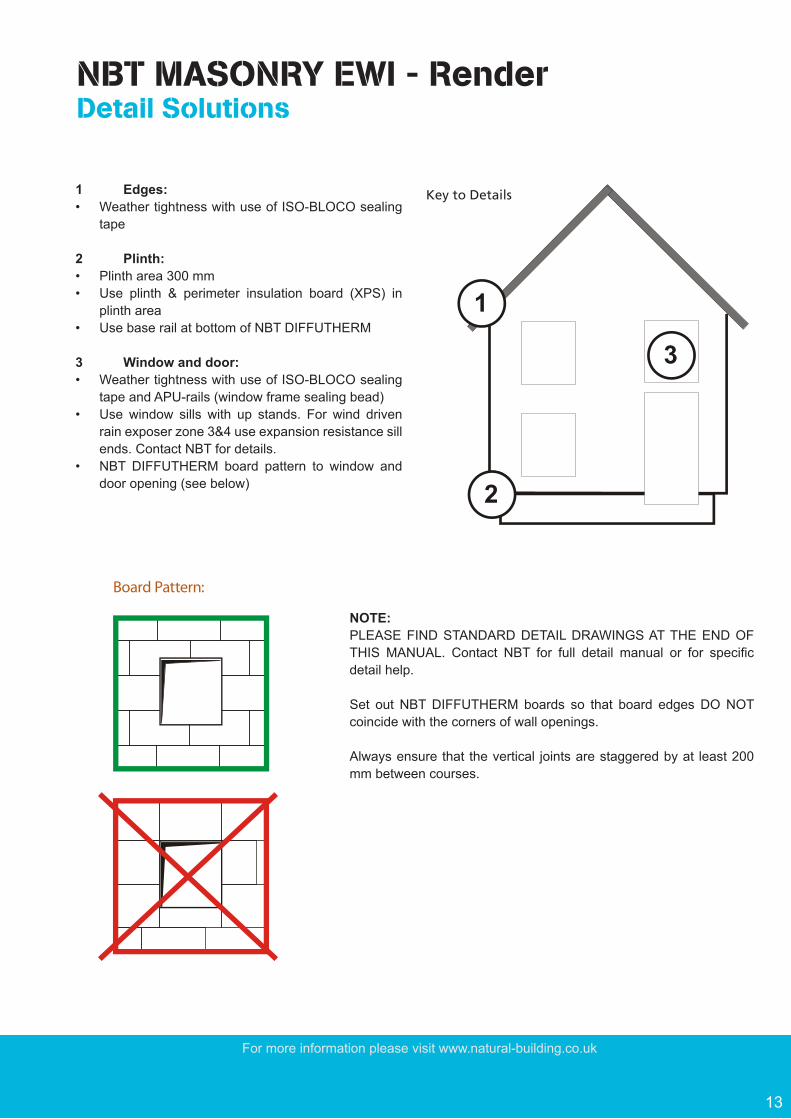
1 Edges:• Weather tightness with use of ISO-BLOCO sealing
tape
2 Plinth:• Plinth area 300 mm• Use plinth & perimeter insulation board (XPS) in
plinth area• Use base rail at bottom of NBT DIFFUTHERM
3 Window and door:• Weather tightness with use of ISO-BLOCO sealing
tape and APU-rails (window frame sealing bead)• Use window sills with up stands. For wind driven
rain exposer zone 3&4 use expansion resistance sill ends. Contact NBT for details.
• NBT DIFFUTHERM board pattern to window and door opening (see below)
NOTE:PLEASE FIND STANDARD DETAIL DRAWINGS AT THE END OF THIS MANUAL. Contact NBT for full detail manual or for specific detail help.
Set out NBT DIFFUTHERM boards so that board edges DO NOT coincide with the corners of wall openings.
Always ensure that the vertical joints are staggered by at least 200 mm between courses.
NBT MASONRY EWI - Render Detail Solutions
Natural Building Technologies LtdThe Hangar, Worminghall Road, Oakley, Buckinghamshire. HP18 9UL
T: 01844 338338 F: 01844 [email protected] www.natural-building.co.uk14
NBT DIFFUTHERM – Components & Accessories
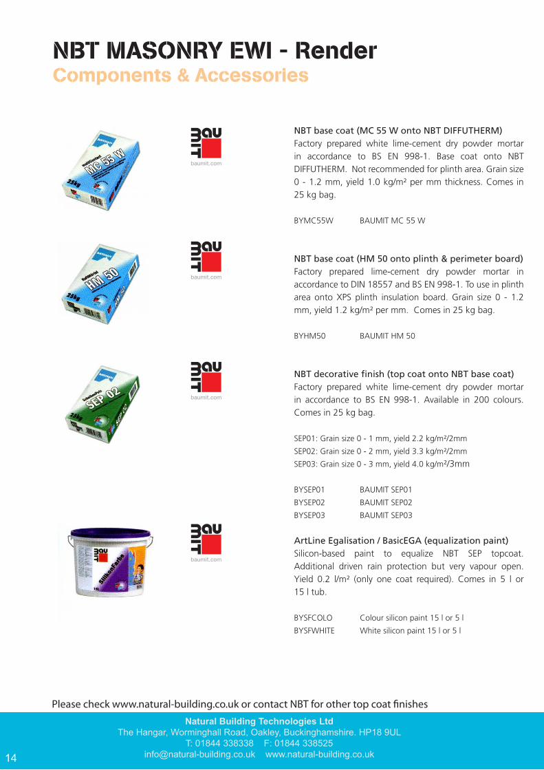
NBT base coat (MC 55 W onto NBT DIFFUTHERM)Factory prepared white lime-cement dry powder mortar in accordance to BS EN 998-1. Base coat onto NBT DIFFUTHERM. Not recommended for plinth area. Grain size 0 - 1.2 mm, yield 1.0 kg/m² per mm thickness. Comes in 25 kg bag.
BYMC55W BAUMIT MC 55 W
NBT base coat (HM 50 onto plinth & perimeter board)Factory prepared lime-cement dry powder mortar in accordance to DIN 18557 and BS EN 998-1. To use in plinth area onto XPS plinth insulation board. Grain size 0 - 1.2 mm, yield 1.2 kg/m² per mm. Comes in 25 kg bag.
BYHM50 BAUMIT HM 50
NBT decorative fi nish (top coat onto NBT base coat)Factory prepared white lime-cement dry powder mortar in accordance to BS EN 998-1. Available in 200 colours. Comes in 25 kg bag.
SEP01: Grain size 0 - 1 mm, yield 2.2 kg/m²/2mm
SEP02: Grain size 0 - 2 mm, yield 3.3 kg/m²/2mm
SEP03: Grain size 0 - 3 mm, yield 4.0 kg/m²/3mm
BYSEP01 BAUMIT SEP01
BYSEP02 BAUMIT SEP02
BYSEP03 BAUMIT SEP03
ArtLine Egalisation / BasicEGA (equalization paint)Silicon-based paint to equalize NBT SEP topcoat. Additional driven rain protection but very vapour open. Yield 0.2 l/m² (only one coat required). Comes in 5 l or 15 l tub.
BYSFCOLO Colour silicon paint 15 l or 5 l
BYSFWHITE White silicon paint 15 l or 5 l
NBT MASONRY EWI - Render Components & Accessories
Please check www.natural-building.co.uk or contact NBT for other top coat finishes

For more information please visit www.natural-building.co.uk
15
NBT MASONRY EWI - Render Components & Accessories
EJOT NTU and EJOT STR-U + STR-U plugFor fixing NBT DIFFUTHERM wood fibre insulation boards onto masonry. Min. wmbedment of 35 mm into masonry. The polystyrenes plug is needed for STR-U inserted in the washer head cavity to ensures least thermal bridging. Heat loss through conduction is therefore substantially reduced. Add existing render depth when calculating fixing length.
EJOT DDA reveal fixings Reveal insulation board anchor fixing for masonry substrate Available in 50mm ad 75mm for 20mm amd 40mm reveal boards respectively.
PVC Balcony Drip Bead with mesh, 6mm, 3794Window head and balcony corner mesh bead with in-built drip profile.
Base rail & clip on profileThe base rail is generally fixed at DPC level to act as a base for the first layer of NBT DIFFUTHERM. The clip-on profile is then clipped to the front edge of the rail to provide a clean edge for the render to finish to. Length 2500 mm.
BYY9146 Base rail aluminium 60 mm*BYY9148 Base rail aluminium 80 mm*BYY9150 Base rail aluminium 100 mm*
BYY9121 Base rail clip aluminium 6 mm*BYY9124 Base rail clip aluminium 10 mm*
* Stainless steel also available
PVC Clip on profileThe PVC clip-on profile with integrated mesh provide better connection with the main mesh.
Length 2500 mm.Drip - 6mm & 10mm
NBT MASONRY EWI - Render Components & Accessories
NTU
STR-U
DDA
Natural Building Technologies LtdThe Hangar, Worminghall Road, Oakley, Buckinghamshire. HP18 9UL
T: 01844 338338 F: 01844 [email protected] www.natural-building.co.uk16
NBT DIFFUTHERM – Components & Accessories
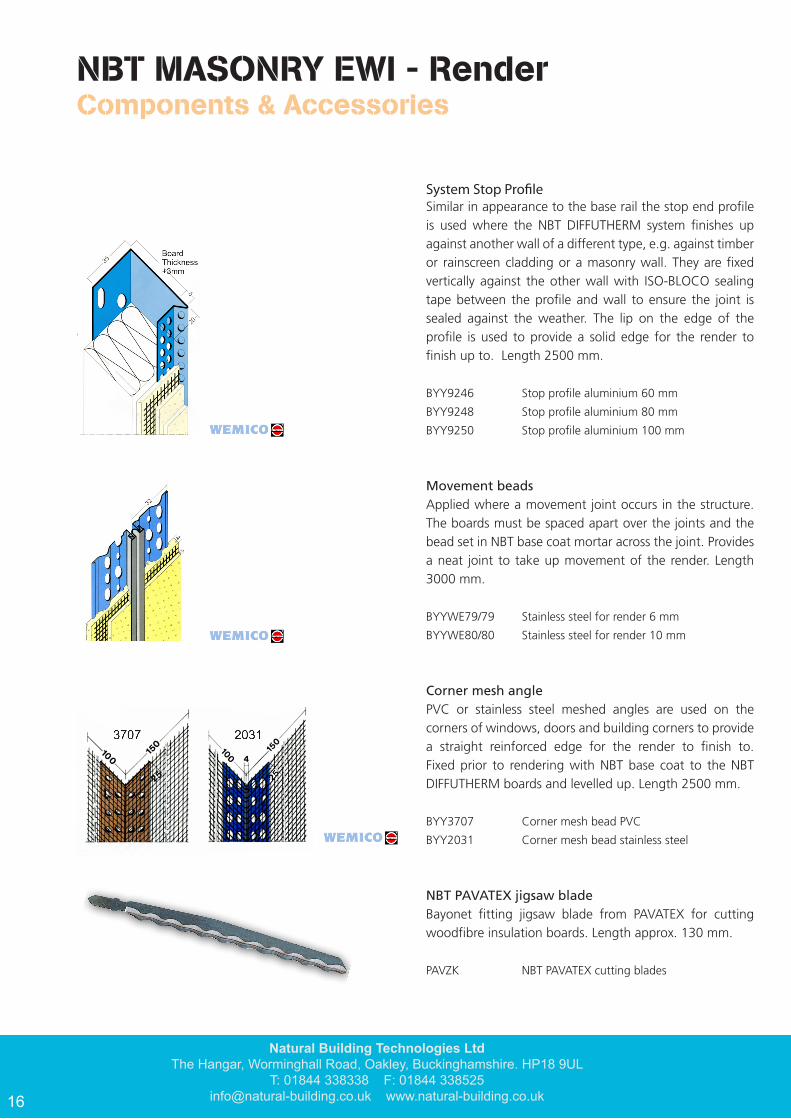
Render stop profi le Similar in appearance to the base rail the stop end profi le is used where the NBT DIFFUTHERM system fi nishes up against another wall of a different type, e.g. against timber or rainscreen cladding or a masonry wall. They are fi xed vertically against the other wall with ISO-BLOCO sealing tape between the profi le and wall to ensure the joint is sealed against the weather. The lip on the edge of the profi le is used to provide a solid edge for the render to fi nish up to. Length 2500 mm.
BYY9246 Stop profi le aluminium 60 mm
BYY9248 Stop profi le aluminium 80 mm
BYY9250 Stop profi le aluminium 100 mm
Movement beadsApplied where a movement joint occurs in the structure. The boards must be spaced apart over the joints and the bead set in NBT base coat mortar across the joint. Provides a neat joint to take up movement of the render. Length 3000 mm.
BYYWE79/79 Stainless steel for render 6 mm
BYYWE80/80 Stainless steel for render 10 mm
Corner mesh anglePVC or stainless steel meshed angles are used on the corners of windows, doors and building corners to provide a straight reinforced edge for the render to fi nish to. Fixed prior to rendering with NBT base coat to the NBT DIFFUTHERM boards and levelled up. Length 2500 mm.
BYY3707 Corner mesh bead PVC
BYY2031 Corner mesh bead stainless steel
NBT PAVATEX jigsaw bladeBayonet fi tting jigsaw blade from PAVATEX for cutting woodfi bre insulation boards. Length approx. 130 mm.
PAVZK NBT PAVATEX cutting blades
NBT MASONRY EWI - Render Components & Accessories
System Stop Profile
For more information please visit www.natural-building.co.uk
17
NBT MASONRY EWI - Render Components & Accessories
NBT DIFFUTHERM – Components & Accessories
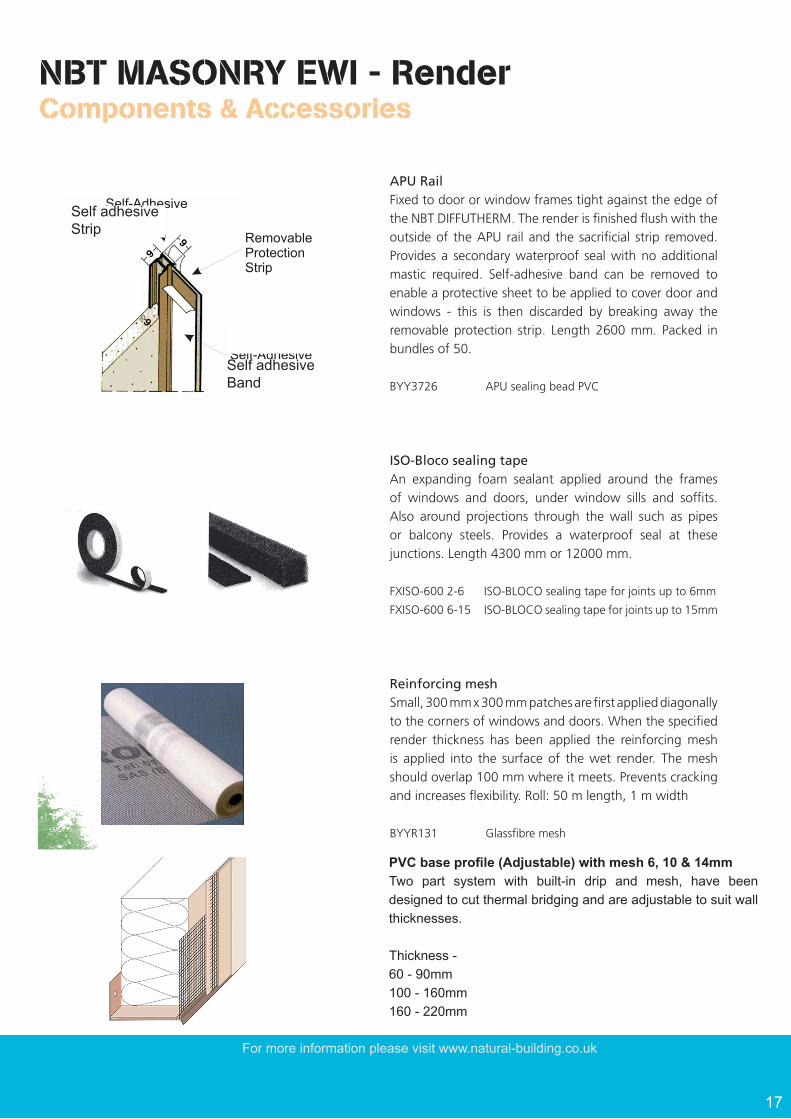
APU Rail Fixed to door or window frames tight against the edge of the NBT DIFFUTHERM. The render is fi nished fl ush with the outside of the APU rail and the sacrifi cial strip removed. Provides a secondary waterproof seal with no additional mastic required. Self-adhesive band can be removed to enable a protective sheet to be applied to cover door and windows - this is then discarded by breaking away the removable protection strip. Length 2600 mm. Packed in bundles of 50.
BYY3726 APU sealing bead PVC
ISO-Bloco sealing tapeAn expanding foam sealant applied around the frames of windows and doors, under window sills and soffi ts. Also around projections through the wall such as pipes or balcony steels. Provides a waterproof seal at these junctions. Length 4300 mm or 12000 mm.
FXISO-600 2-6 ISO-BLOCO sealing tape for joints up to 6mm
FXISO-600 6-15 ISO-BLOCO sealing tape for joints up to 15mm
Reinforcing meshSmall, 300 mm x 300 mm patches are fi rst applied diagonally to the corners of windows and doors. When the specifi ed render thickness has been applied the reinforcing mesh is applied into the surface of the wet render. The mesh should overlap 100 mm where it meets. Prevents cracking and increases fl exibility. Roll: 50 m length, 1 m width
BYYR131 Glassfi bre mesh
RemovableProtection Strip
Self-AdhesiveBand
3726
Self-AdhesiveStrip
30
Self adhesive Strip
Self adhesive Band
NBT MASONRY EWI - Render Components & Accessories
PVC base profile (Adjustable) with mesh 6, 10 & 14mmTwo part system with built-in drip and mesh, have been designed to cut thermal bridging and are adjustable to suit wall thicknesses.
Thickness - 60 - 90mm100 - 160mm160 - 220mm
Nat
ural
Bui
ldin
g Te
chno
logi
es L
tdTh
e H
anga
r, W
orm
ingh
all R
oad,
Oak
ley,
Buc
king
ham
shire
. HP
18 9
UL
T: 0
1844
338
338
F:
018
44 3
3852
5in
fo@
natu
ral-b
uild
ing.
co.u
k
ww
w.n
atur
al-b
uild
ing.
co.u
k
Nat
ural
Bui
ldin
g Te
chno
logi
es L
tdTh
e H
anga
r, W
orm
ingh
all R
oad,
Oak
ley,
Buc
king
ham
shire
. HP
18 9
UL
T: 0
1844
338
338
F:
018
44 3
3852
5in
fo@
natu
ral-b
uild
ing.
co.u
k
ww
w.n
atur
al-b
uild
ing.
co.u
k
18
NBT MASONRY EWI - Render Eaves Detail
Nat
ural
Bui
ldin
g Te
chno
logi
es L
tdTh
e H
anga
r, W
orm
ingh
all R
oad,
Oak
ley,
Buc
king
ham
shire
. HP
18 9
UL
T: 0
1844
338
338
F:
018
44 3
3852
5in
fo@
natu
ral-b
uild
ing.
co.u
k
ww
w.n
atur
al-b
uild
ing.
co.u
k
19RE
TRO
FIT
EW
I - N
BT
RE
ND
ER
SYS
TEM
- E
ave
s D
eta
ilR
e-E
WI-
R-W
R-0
1
1 2 3 45
6K
EY T
O C
OM
PO
NEN
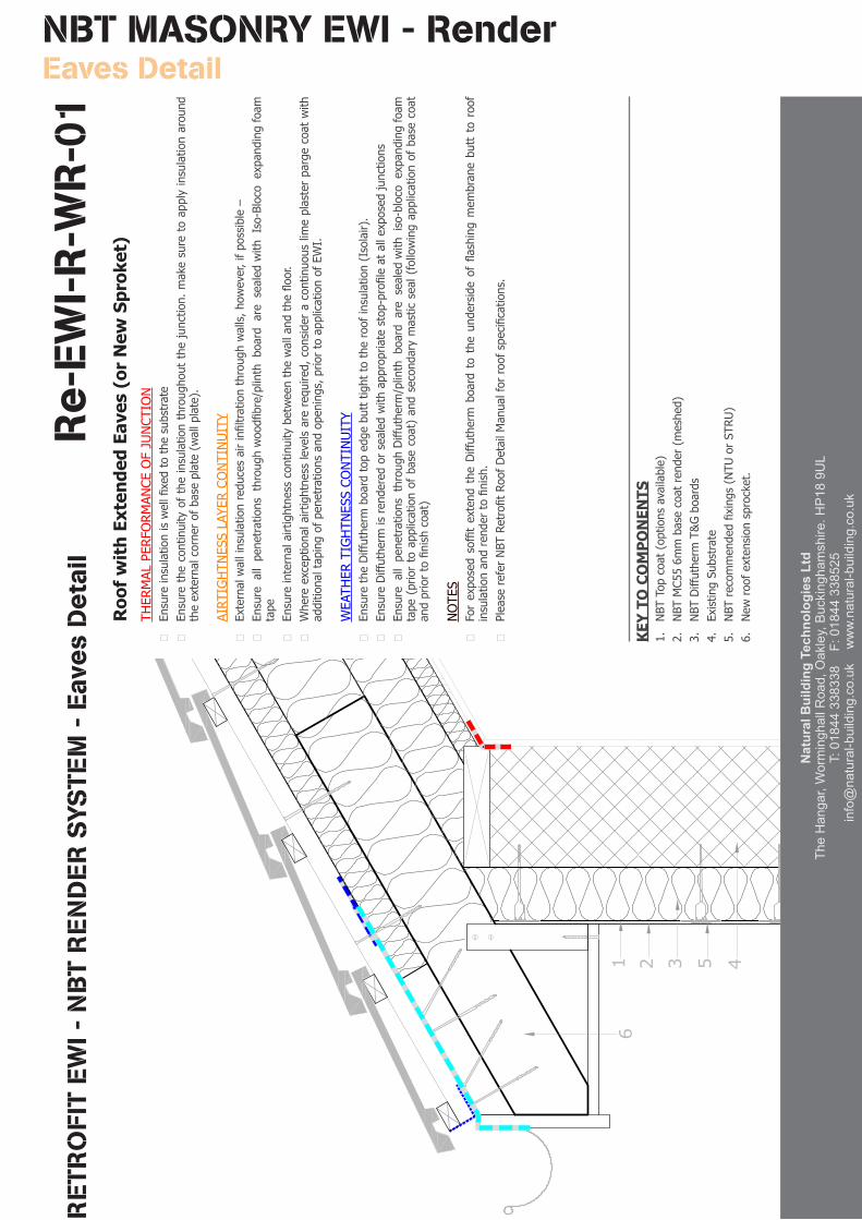
TS1.NBTTopcoat(optionsavailable)
2.NBTMC556mmbasecoatrender(meshed)
3.NBTDiffuthermT&Gboards
4.ExistingSubstrate
5.NBTrecommendedfixings(NTUorSTRU)
6.Newroofextensionsprocket.
Roo
f w
ith
Exte
nded
Eav
es (
or N
ew S
prok
et)
THERMALPERFORMANCEOFJUNCTION
Ensureinsulationiswellfixedtothesubstrate
Ensurethecontinuityoftheinsulationthroughoutthejunction.makesuretoapplyinsulationaround
theexternalcornerofbaseplate(wallplate).
AIRTIGHTNESSLAYERCONTINUITY
Externalwallinsulationreducesairinfiltrationthroughwalls,however,ifpossible–
Ensureallpenetrationsthroughwoodfibre/plinthboardaresealedwithIso-Blocoexpandingfoam
tape
Ensureinternalairtightnesscontinuitybetweenthewallandthefloor.
Whereexceptionalairtightnesslevelsarerequired,consideracontinuouslimeplasterpargecoatwith
additionaltapingofpenetrationsandopenings,priortoapplicationofEWI.
WEATHERTIGHTNESSCONTINUITY
EnsuretheDiffuthermboardtopedgebutttighttotheroofinsulation(Isolair).
EnsureDiffuthermisrenderedorsealedwithappropriatestop-profileatallexposedjunctions
EnsureallpenetrationsthroughDiffutherm/plinthboardaresealedwithiso-blocoexpandingfoam
tape(priortoapplicationofbasecoat)andsecondarymasticseal(followingapplicationofbasecoat
andpriortofinishcoat)
NOTES
ForexposedsoffitextendtheDiffuthermboardtotheundersideofflashingmembranebutttoroof
insulationandrendertofinish.
PleasereferNBTRetrofitRoofDetailManualforroofspecifications.
Nat
ural
Bui
ldin
g Te
chno
logi
es L
tdTh
e H
anga
r, W
orm
ingh
all R
oad,
Oak
ley,
Buc
king
ham
shire
. HP
18 9
UL
T: 0
1844
338
338
F:
018
44 3
3852
5in
fo@
natu
ral-b
uild
ing.
co.u
k
ww
w.n
atur
al-b
uild
ing.
co.u
k
Nat
ural
Bui
ldin
g Te
chno
logi
es L
tdTh
e H
anga
r, W
orm
ingh
all R
oad,
Oak
ley,
Buc
king
ham
shire
. HP
18 9
UL
T: 0
1844
338
338
F:
018
44 3
3852
5in
fo@
natu
ral-b
uild
ing.
co.u
k
ww
w.n
atur
al-b
uild
ing.
co.u
k
Nat
ural
Bui
ldin
g Te
chno
logi
es L
tdTh
e H
anga
r, W
orm
ingh
all R
oad,
Oak
ley,
Buc
king
ham
shire
. HP
18 9
UL
T: 0
1844
338
338
F:
018
44 3
3852
5in
fo@
natu
ral-b
uild
ing.
co.u
k
ww
w.n
atur
al-b
uild
ing.
co.u
k
18
Nat
ural
Bui
ldin
g Te
chno
logi
es L
tdTh
e H
anga
r, W
orm
ingh
all R
oad,
Oak
ley,
Buc
king
ham
shire
. HP
18 9
UL
T: 0
1844
338
338
F:
018
44 3
3852
5in
fo@
natu
ral-b
uild
ing.
co.u
k
ww
w.n
atur
al-b
uild
ing.
co.u
k
19
NBT MASONRY EWI - Render Plinth Detail 1
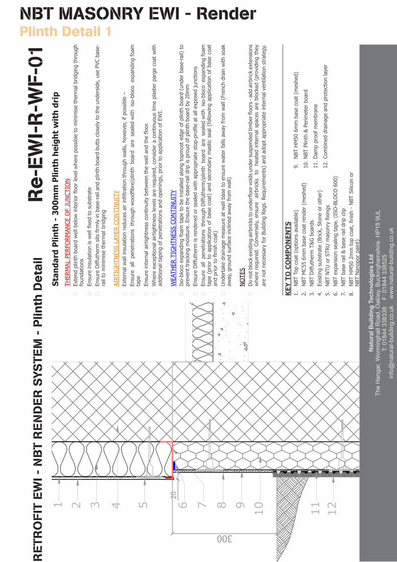
Stan
dard
Plin
th -
300
mm
Plin
th h
eigh
t w
ith
drip
THERMALPERFORMANCEOFJUNCTION
Extendplinthboardwellbelowinteriorfloorlevelwherepossibletominimisethermalbridgingthrough
foundations
Ensureinsulationiswellfixedtosubstrate
EnsureDiffuthermsitsfirmlyinbase-railandplinthboardbuttscloselytotheunderside,usePVCbase-
railtominimisethermalbridging
AIRTIGHTNESSLAYERCONTINUITY
Externalwallinsulationreducesairinfiltrationthroughwalls,however,ifpossible–
Ensureallpenetrationsthroughwoodfibre/plinthboardaresealedwithiso-blocoexpandingfoam
tape
Ensureinternalairtightnesscontinuitybetweenthewallandthefloor.
Whereexceptionalairtightnesslevelsarerequired,consideracontinuouslimeplasterpargecoatwith
additionaltapingofpenetrationsandopenings,priortoapplicationofEWI.
WEATHERTIGHTNESSCONTINUITY
Iso-blocoexpandingfoamtapetobeinstalledalongtopmostedgeofplinthboard(underbase-rail)to
preventtrackingmoisture.Ensurethebase-raildripisproudofplinthboardby20mm
EnsureDiffuthermisrenderedorsealedwithappropriatestop-profileatallexposedjunctions
EnsureallpenetrationsthroughDiffutherm/plinthboardaresealedwithiso-blocoexpandingfoam
tape(priortoapplicationofbasecoat)andsecondarymasticseal(followingapplicationofbasecoat
andpriortofinishcoat)
Undertakedrainagemeasureatwallbasetoensurewaterfallsawayfromwall(Frenchdrainwithsoak
away,groundsurfaceinclinedawayfromwall)
NOTES
Donotblockexistingairbrickstounderfloorvoidsundersuspendedtimberfloors-addairbrickextensions
whererequired.Conversely,ensureairbrickstoheatedinternalspacesareblocked(providingthey
arenotnecessaryforBuildingRegs.Requirements)andadoptappropriateinternalventilationstrategy.
RE
TRO
FIT
EW
I - N
BT
RE
ND
ER
SYS
TEM
- P
linth
De
tail
Re
-EW
I-R
-WF-
011 2 3 4 5 6 7 8 9 10 11 12
20
300
1.NBTTopcoat(optionsavailable)
2.NBTMC556mmbasecoatrender(meshed)
3.NBTDiffuthermT&Gboards
4.Existingsubstrate(Brick,Stoneorother)
5.NBTNTUorSTRUmasonryfixings
6.NBTexpansionsealingtape.(ISO-BLOCO600)
7.NBTbaserail&baseraildripclip
8.NBTHM502mmtopcoat,finish-NBTSiliconor
NBTNanoporpaint)
9.NBTHM506mmbasecoat(meshed)
10.NBTPlinth&Perimeterboard
11.Dampproofmembrane
12.Combineddrainageandprotectionlayer
KEY
TO
CO
MP
ON
ENTS
Nat
ural
Bui
ldin
g Te
chno
logi
es L
tdTh
e H
anga
r, W
orm
ingh
all R
oad,
Oak
ley,
Buc
king
ham
shire
. HP
18 9
UL
T: 0
1844
338
338
F:
018
44 3
3852
5in
fo@
natu
ral-b
uild
ing.
co.u
k
ww
w.n
atur
al-b
uild
ing.
co.u
k
Nat
ural
Bui
ldin
g Te
chno
logi
es L
tdTh
e H
anga
r, W
orm
ingh
all R
oad,
Oak
ley,
Buc
king
ham
shire
. HP
18 9
UL
T: 0
1844
338
338
F:
018
44 3
3852
5in
fo@
natu
ral-b
uild
ing.
co.u
k
ww
w.n
atur
al-b
uild
ing.
co.u
k
20
NBT MASONRY EWI - Render Plinth Detail 2
RE
TRO
FIT
EW
I - N
BT
RE
ND
ER
SYS
TEM
- P
linth
De
tail
Re
-EW
I-R
-WF-
02
1 2 3 4 5 6 7 9 108 11 12
20
150
300
8
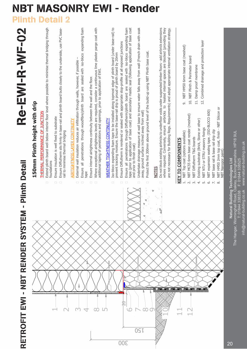
1.NBTTopcoat(optionsavailable)
2.NBTMC556mmbasecoatrender(meshed)
3.NBTDiffuthermT&Gboards
4.Existingsubstrate(Brick,Stoneorother)
5.NBTNTUorSTRUmasonryfixings
6.NBTexpansionsealingtape.(ISO-BLOCO600)
7.NBTbaserail&baseraildripclip
8.NBTHM502mmtopcoat,finish-NBTSiliconor
NBTNanoporpaint)
9.NBTHM506mmbasecoat(meshed)
10.NBTPlinth&Perimeterboard
11.Dampproofmembrane
12.Combineddrainageandprotectionlayer
150m
m P
linth
hei
ght
wit
h dr
ipTHERMALPERFORMANCEOFJUNCTION
Extendplinthboardwellbelowinteriorfloorlevelwherepossibletominimisethermalbridgingthrough
foundations
Ensureinsulationiswellfixedtosubstrate
EnsureDiffuthermsitsfirmlyinbase-railandplinthboardbuttscloselytotheunderside,usePVCbase-
railtominimisethermalbridging
AIRTIGHTNESSLAYERCONTINUITY
Externalwallinsulationreducesairinfiltrationthroughwalls,however,ifpossible–
Ensureallpenetrationsthroughwoodfibre/plinthboardaresealedwithiso-blocoexpandingfoam
tape
Ensureinternalairtightnesscontinuitybetweenthewallandthefloor.
Whereexceptionalairtightnesslevelsarerequired,consideracontinuouslimeplasterpargecoatwith
additionaltapingofpenetrationsandopenings,priortoapplicationofEWI.
WEATHERTIGHTNESSCONTINUITY
Iso-blocoexpandingfoamtapetobeinstalledalongtopmostedgeofplinthboard(underbase-rail)to
preventtrackingmoisture.Ensurethebase-raildripisproudofplinthboardby20mm
EnsureDiffuthermisrenderedorsealedwithappropriatestop-profileatallexposedjunctions
EnsureallpenetrationsthroughDiffutherm/plinthboardaresealedwithiso-blocoexpandingfoam
tape(priortoapplicationofbasecoat)andsecondarymasticseal(followingapplicationofbasecoat
andpriortofinishcoat)
Undertakedrainagemeasureatwallbasetoensurewaterfallsawayfromwall(Frenchdrainwithsoak
away,groundsurfaceinclinedawayfromwall)
Protectthefirst300mmabovegroundlevelofthebuild-upusingNBTPlinthbasecoat.
NOTES
Donotblockexistingairbrickstounderfloorvoidsundersuspendedtimberfloors-addairbrickextensions
whererequired.Conversely,ensureairbrickstoheatedinternalspacesareblocked(providingthey
arenotnecessaryforBuildingRegs.Requirements)andadoptappropriateinternalventilationstrategy.
KEY
TO
CO
MP
ON
ENTS
Nat
ural
Bui
ldin
g Te
chno
logi
es L
tdTh
e H
anga
r, W
orm
ingh
all R
oad,
Oak
ley,
Buc
king
ham
shire
. HP
18 9
UL
T: 0
1844
338
338
F:
018
44 3
3852
5in
fo@
natu
ral-b
uild
ing.
co.u
k
ww
w.n
atur
al-b
uild
ing.
co.u
k
Nat
ural
Bui
ldin
g Te
chno
logi
es L
tdTh
e H
anga
r, W
orm
ingh
all R
oad,
Oak
ley,
Buc
king
ham
shire
. HP
18 9
UL
T: 0
1844
338
338
F:
018
44 3
3852
5in
fo@
natu
ral-b
uild
ing.
co.u
k
ww
w.n
atur
al-b
uild
ing.
co.u
k
Nat
ural
Bui
ldin
g Te
chno
logi
es L
tdTh
e H
anga
r, W
orm
ingh
all R
oad,
Oak
ley,
Buc
king
ham
shire
. HP
18 9
UL
T: 0
1844
338
338
F:
018
44 3
3852
5in
fo@
natu
ral-b
uild
ing.
co.u
k
ww
w.n
atur
al-b
uild
ing.
co.u
k
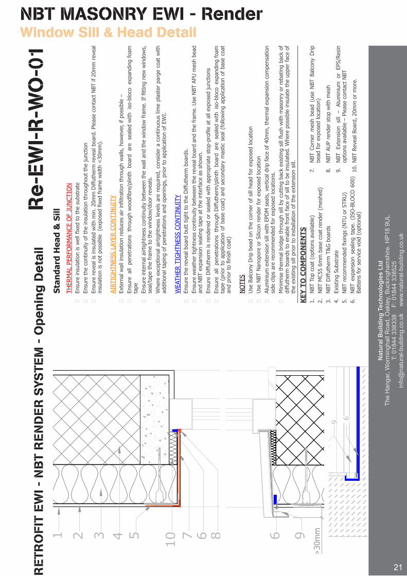
Stan
dard
Hea
d &
Sill
THERMALPERFORMANCEOFJUNCTION
Ensureinsulationiswellfixedtothesubstrate
Ensurethecontinuityoftheinsulationthroughoutthejunction
Ensurerevealisinsulatedwithmin.20mmDiffuthermrevealboard.PleasecontactNBTif20mmreveal
insulationisnotpossible(exposedfixedframewidth<30mm).
AIRTIGHTNESSLAYERCONTINUITY
Externalwallinsulationreducesairinfiltrationthroughwalls,however,ifpossible–
Ensureallpenetrationsthroughwoodfibre/plinthboardaresealedwithiso-blocoexpandingfoam
tape
Ensureinternalairtightnesscontinuitybetweenthewallandthewindowframe.Iffittingnewwindows,
seal/tapetheframetothewindow/doorreveals.
Whereexceptionalairtightnesslevelsarerequired,consideracontinuouslimeplasterpargecoatwith
additionaltapingofpenetrationsandopenings,priortoapplicationofEWI.
WEATHERTIGHTNESSCONTINUITY
EnsuretherevealboardbutttighttotheDiffuthermboards.
Ensureweathertightnesscontinuitybetweentherevealboardandtheframe.UseNBTAPUmeshbead
andNBTexpansionsealingtapeattheinterfaceasshown.
EnsureDiffuthermisrenderedorsealedwithappropriatestop-profileatallexposedjunctions
EnsureallpenetrationsthroughDiffutherm/plinthboardaresealedwithiso-blocoexpandingfoam
tape(priortoapplicationofbasecoat)andsecondarymasticseal(followingapplicationofbasecoat
andpriortofinishcoat)
NOTES
UseBalconyDripbeadonthecornerofsillheadforexposedlocation
UseNBTNanoporeorSiliconrenderforexposedlocation
AluminiumextensionsillwithEPDMseals,verticaldripfaceof40mm,thermalexpansioncompensation
sideclipsarerecommendedforexposedlocations.
Minimisethermalbridgethroughsillbycuttingbackexistingsillflushwithmasonryorrebatingbackof
diffuthermboardstoenablefrontfaceofsilltobeinsulated.Wherepossibleinsulatetheupperfaceof
theexistingsillpriortoinstallationoftheextensionsill.
21
NBT MASONRY EWI - Render Window Sill & Head Detail
RE
TRO
FIT
EW
I - N
BT
RE
ND
ER
SYS
TEM
- O
pe
nin
g D
eta
ilR
e-E
WI-
R-W
O-0
11 2 3 4 5 7 6 6 910
>30mm8
1.NBTTopcoat(optionsavailable)
2.NBTMC556mmbasecoatrender(meshed)
3.NBTDiffuthermT&Gboards
4.ExistingSubstrate
5.NBTrecommendedfixings(NTUorSTRU)
6.NBTexpansionsealingtape.(ISO-BLOCO600)
Battensforservicevoid(optional)
7.NBTCornermeshbead(useNBTBalconyDrip
beadforexposedlocation)
8.NBTAUPrenderstopwithmesh
9.NBTExtensionsill–AluminiumorEPS/Resin
optionsavailable–PleasecontactNBT
10.NBTRevealBoard,20mmormore.
KEY
TO
CO
MP
ON
ENTS
1 2 3 4 5 7 6 6 910
>30mm8
9 6
Nat
ural
Bui
ldin
g Te
chno
logi
es L
tdTh
e H
anga
r, W
orm
ingh
all R
oad,
Oak
ley,
Buc
king
ham
shire
. HP
18 9
UL
T: 0
1844
338
338
F:
018
44 3
3852
5in
fo@
natu
ral-b
uild
ing.
co.u
k
ww
w.n
atur
al-b
uild
ing.
co.u
k
NBT MASONRY EWI - Render Roof Flashing Abutment Detail
RE
TRO
FIT
EW
I - N
BT
RE
ND
ER
SYS
TEM
- P
orc
h/C
ano
py
Re
-EW
I-R
-WR
-06
KEY
TO
CO
MP
ON
ENTS
1 2 3 4 5 6 7 8 9
>150
20
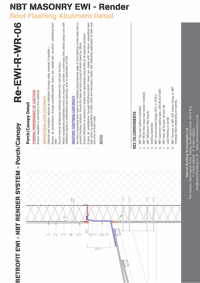
1.NBTTopcoat(optionsavailable)
2.NBTMC556mmbasecoatrender(meshed)
3.NBTDiffuthermT&Gboards
4.ExistingSubstrate
5.NBTrecommendedfixings(NTUorSTRU)
6.NBTexpansionsealingtape.(ISO-BLOCO600)
7.NBTbaserail&baseraildripclip
8.Leadflashingorsimilar
9.NBTThermaxorNBTSDFFramefixingsorNBT
montageblockdependingonloading.
Por
ch/C
anop
y D
etai
lTHERMALPERFORMANCEOFJUNCTION
Ensureinsulationiswellfixedtothesubstrate
AIRTIGHTNESSLAYERCONTINUITY
Externalwallinsulationreducesairinfiltrationthroughwalls,however,ifpossible–
Ensureallpenetrationsthroughwoodfibre/plinthboardaresealedwithiso-blocoexpandingfoam
tape
Ensureinternalairtightnesscontinuitybetweenthewallandthefloor.
Whereexceptionalairtightnesslevelsarerequired,consideracontinuouslimeplasterpargecoatwith
additionaltapingofpenetrationsandopenings,priortoapplicationofEWI.
WEATHERTIGHTNESSCONTINUITY
Iso-blocoexpandingfoamtapetobeinstalledalongtopmostedgeofleadflashing(underbase-rail)to
preventtrackingmoisture.Ensurethebase-raildripisproudofplinthboardby20mm
EnsureDiffuthermisrenderedorsealedwithappropriatestop-profileatallexposedjunctions
EnsureallpenetrationsthroughDiffutherm/plinthboardaresealedwithiso-blocoexpandingfoam
tape(priortoapplicationofbasecoat)andsecondarymasticseal(followingapplicationofbasecoat
andpriortofinishcoat)
NOTES
For more information please visit www.natural-building.co.uk
23
Nat
ural
Bui
ldin
g Te
chno
logi
es L
tdTh
e H
anga
r, W
orm
ingh
all R
oad,
Oak
ley,
Buc
king
ham
shire
. HP
18 9
UL
T: 0
1844
338
338
F:
018
44 3
3852
5in
fo@
natu
ral-b
uild
ing.
co.u
k
ww
w.n
atur
al-b
uild
ing.
co.u
k
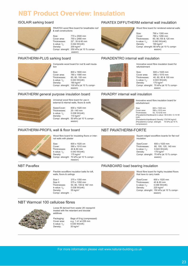
ISOLAIR sarking boardPAVATEX wood fibre board for breathable roof & wall constructions
Size: 770 x 2500 mmCover area: 750 x 2480 mmThicknesses: 22*, 35 & 60 mmk-value / lD: 0.044 W/(mK)Density: 200 kg/m3
Compr. strenght: 250 kPa (at 10 % compr- ession)
PAVATEX DIFFUTHERM external wall insulation Wood fibre board for rendered external walls
Size: 790 x 1300 mm Cover: 780 x 1290 mmThicknesses: 60, 80,100 & 120 mmk-value / lD: 0.043 W/(mK)Density: 190 kg/m3
Compr. strenght: 80 kPa (at 10 % compr- ession)
PAVATHERM-PLUS sarking boardComposite wood board for roof & wall insula-tion
Size: 800 x 1600 mmCover area: 780 x 1580 mmThicknesses: 60, 80, 100 mmk-value / lD: 0.043 W/(mK)Density: 180 kg/m3
Compr. strenght: 100 kPa (at 10 % compr- ession)
PAVADENTRO internal wall insulationInnovative wood fibre insulation board for refurbishment
Size: 600 x 1020 mm Cover area: 590 x 1010 mmThicknesses: 40, 60, 80 & 100 mmk-value / lD: 0.043 W/(mK)Density: 175 kg/m3
Compr. strenght: 70 kPa (at 10 % compr- ession
Innovative wood fibre insulation board for refurbishment
Size: 600 x 1020 mm Cover area: 590 x 1010 mmThicknesses: 52, 72 & 92 mm(Pavadentro/Hardboard) k-value / lD:0.043 / 0.14 W/(mK)(Pavadentro/Hardboard) Density:175/740 kg/m3(Pavadentro) Compr. strenght: 70 kPa (at 10 % compression)
PAVATHERM general purpose insulation boardUniversal wood fibre board for use in external & internal walls, floors & roofs
Sizes/Cover: 600 x 1020 mmThicknesses: 20 -140 mmk-value / lD: 0.038 W/(mK)Density: 110 kg/m3
Compr. strenght: 50 kPa (at 10 % compr- ession)
PAVADRY internal wall insulation
PAVATHERM-PROFIL wall & floor boardWood fibre board for insulating floors or inter-nal walls with plaster
Size: 600 x 1020 cmCover: 590 x 1010 mmThicknesses: 40 & 60 mmk-value / lD: 0.043 W/(mK)Density: 175 kg/m3
Compr. strenght: 70 kPa (at 10 % compr- ression)
NBT PavaflexFlexible woodfibre insulation batts for loft, walls, floors & ceilings
Size I: 375 x 1350 mmSize II: 575 x 1350 mmThicknesses: 50, 80, 100 & 140* mmk-value / lD: 0.038 W/(mK)Density: 55 kg/m3
Compr. strenght: -
NBT Warmcel 100 cellulose fibres Loose fill derived from waste UK newsprint treated with fire retardant and biocidal additives
Packaging: Bags of 8 kg (compressed) Cover area: e.g. 1 m2 at 228 mmk-value / lD: 0.035 W/(mK)Density: 35 kg/m3
NBT PAVATHERM-FORTESquare edged woodfibre boards for flat roof insulation
Size/Cover: 600 x 1020 mmThicknesses: 80, 100, 120, 140 mmk-value / lD: 0.043 W/(mK)Density: 175 kg/m3
Compr. strenght: 70 kPa (at 10 % compr- ession)
NBT Product Overview: Insulation
PAVABOARD load bearing insulationWood fibre board for highly insulated floors that have to carry loads
Size/Cover: 600 x 1020 mm Thicknesses: 40 & 60 mmk-value / lD: 0.046 W/(mK)Density: 220 kg/m3
Compr. strenght: 150 kPa (at 10 % compr- ession)

Natural Building Technologies LtdThe Hangar, Worminghall Road, Oakley, Buckinghamshire. HP18 9UL
T: 01844 338338 F: 01844 [email protected] www.natural-building.co.uk24
high performance systems NBT PAVATEX woodfibre systems provide exceptional thermal & acoustic insulation, summer overheating protection and moisture control for the whole building in wall roof and floor
low carbon, renewable products NBT PAVATEX boards are made of waste wood and lock up the equivalent of ca. 11 tonnes of CO2 per building. Raw material resources are entirely renewable, unlimited and FSC certified
healthy housing NBT PAVATEX insulation boards are certified by natureplus as non-polluting and the NBT systems lead to breathable constructions; NBT PAVATEX insulation is specified exclusively by the Sentinal Haus Institute for healthy housing
tried & tested systems NBT PAVATEX woodfibre insulation are wiedely used across Europe in all climates and conditions; pysical values are 3rd party tested and guarenteed and production is according to BS EN
local service & support Pavatex‘s partner in the UK is Natural Build-ing Technologies (NBT) who are a Technical Sales Company with nationwide coverage based in Oakley, Bucks. NBT lead the UK sustainable materials & systems for high performance building shells
swiss quality & know-how for the UK produced and developed in Switzerland for more than 70 years by the world‘s most inovative woodfibre insulation manufacturer
Natural Building Materials and SystemsNatural Building Materials and Systems
Subject to alteration due to development-Nov, 2014 - US