Technical Manual for the Steady Filament Beacon FB12 ... · The internal earth terminal, where...
12
© MEDC 2019 01/19 Technical Manual for the Steady Filament Beacon FB12 Manual Técnico para o alarme visual FB12 Please note that every care has been taken to ensure the accuracy of our technical manual. We do not, however, accept responsibility for damage, loss or expense resulting from any error or omission. We reserve the right to make alterations in line with technical advances and industry standards. É importante ressaltar que adotamos todas as medidas necessárias para garantir a exatidão dos nossos manuais técnicos. Porém, não aceitamos a responsabilidade por danos, perdas ou despesas resultantes de qualquer erro ou omissão. Reservamo-nos o direito de efetuar alterações em sintonia com os avanços técnicos e padrões industriais.
Transcript of Technical Manual for the Steady Filament Beacon FB12 ... · The internal earth terminal, where...

© MEDC 2019 01/19
Technical Manual for the Steady Filament Beacon FB12 Manual Técnico para o alarme visual FB12
Please note that every care has been taken to ensure the accuracy of our technical manual. We do not, however, accept responsibility for damage, loss or expense resulting from any error or omission. We reserve the right to make alterations in line with technical advances and industry standards.
É importante ressaltar que adotamos todas as medidas necessárias para garantir a exatidão dos nossos manuais técnicos. Porém, não aceitamos a responsabilidade por danos, perdas ou despesas resultantes de qualquer erro ou omissão. Reservamo-nos o direito de efetuar alterações em sintonia com os avanços técnicos e padrões industriais.
01/19 © MEDC 2019
English1.0 INTRODUCTIONThese certified steady beacons have been designed for use in potentially explosive atmospheres and harsh environmental conditions. The enclosures are suitable for use offshore or onshore, where light weight combined with corrosion resistance is required.
The beacon housing is manufactured completely from a U.V. stable, glass reinforced polyester. Stainless steel screws and mounting bracket are incorporated ensuring a totally corrosion free product.
Units can be painted to customer specification and supplied with identification labels.
2.0 INSTALLATION
General
When installing and operating explosion-protected equipment, requirements for selection, installation and op-eration should be referred to eg. IEE Wiring Regulations and the ‘National Electrical Code’ in North America. Additional national and/or local requirements may apply.
Ensure that only the correct listed or certified stopping plugs are used to blank off unused gland entry points and that the NEMA/IP rating of the unit is maintained. MEDC recommend the use of a sealing compound such as HYLOMAR PL32 on the threads of glands and stopping plugs in order to maintain the IP rating of the unit.
The unit can either be directly mounted using the inserts moulded into the back of the enclosure (standard), or a backstrap (optional) can be fixed to the base of the unit thus giving an optional mounting position for when direct mounting is deemed unsuitable.
There are 2 off M8 inserts in the base of the enclosure for direct mounting.
Please note: for direct mounting, observe the following formula to determine length of fixing screw required:-Length of screw = Thickness of mounting surface + 10mm
There are 2 off Ø11.5mm mounting holes in the optional backstrap. These have been designed to accept an M10 screw or bolt
MEDC recommend the use of stainless steel screws. Ensure that all nuts, bolts and fixings are secure.
Note: The cover fixing screws for the unit must be stainless steel grade A2-70 minimum, M8 x 30mm long socket head cap screws
Cable Termination
CAUTION: Before removing the cover assembly, ensure that the power to the unit is isolated.
Unscrew and remove the 6 off M8 screws (6.0mm hexagon key) holding the cover assembly to the base. Keep in a safe, accessible location as they are non-captive.Twist the cover assembly gently clockwise and anti-clockwise, whilst pulling it away from the base. Remove to gain access to the interior.Cable termination should be in accordance with specifications applying to the required application. MEDC rec-ommends that all cables and cores should be correctly identified. Please refer to the wiring diagram provided with the product.Ensure that only the correct listed or certified cable glands are used and that the assembly is shrouded and correctly earthed.All cable glands should be of an equivalent NEMA/IP rating to that of the beacon and integrated with the unit such that this rating is maintained.
© MEDC 2019 01/19
The internal earth terminal, where fitted, must be used for the equipment grounding.Once termination is complete, carefully replace the cover assembly back onto the base, avoiding damage to the mating surfaces. Replace the 6 off M8 screws (6.0mm A/F hexagon key) into the holes in the cover as-sembly and tighten evenly. Ensure the O-ring is seated correctly on the cover during re-assembly. Ensure the required maximum gap of 0.2mm is maintained between the cover and the base once assembled.
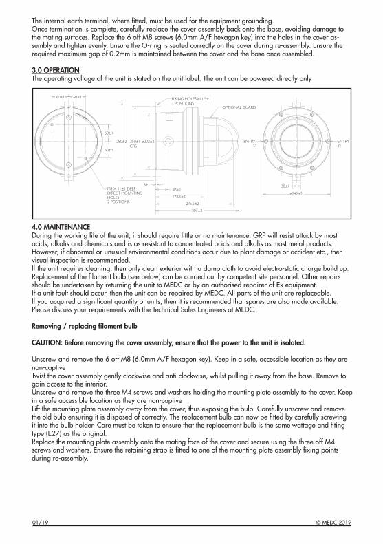
3.0 OPERATIONThe operating voltage of the unit is stated on the unit label. The unit can be powered directly only
4.0 MAINTENANCEDuring the working life of the unit, it should require little or no maintenance. GRP will resist attack by most acids, alkalis and chemicals and is as resistant to concentrated acids and alkalis as most metal products.However, if abnormal or unusual environmental conditions occur due to plant damage or accident etc., then visual inspection is recommended.If the unit requires cleaning, then only clean exterior with a damp cloth to avoid electro-static charge build up.Replacement of the filament bulb (see below) can be carried out by competent site personnel. Other repairs should be undertaken by returning the unit to MEDC or by an authorised repairer of Ex equipment.If a unit fault should occur, then the unit can be repaired by MEDC. All parts of the unit are replaceable.If you acquired a significant quantity of units, then it is recommended that spares are also made available. Please discuss your requirements with the Technical Sales Engineers at MEDC.
Removing / replacing filament bulb
CAUTION: Before removing the cover assembly, ensure that the power to the unit is isolated.
Unscrew and remove the 6 off M8 (6.0mm A/F hexagon key). Keep in a safe, accessible location as they are non-captiveTwist the cover assembly gently clockwise and anti-clockwise, whilst pulling it away from the base. Remove to gain access to the interior.Unscrew and remove the three M4 screws and washers holding the mounting plate assembly to the cover. Keep in a safe accessible location as they are non-captiveLift the mounting plate assembly away from the cover, thus exposing the bulb. Carefully unscrew and remove the old bulb ensuring it is disposed of correctly. The replacement bulb can now be fitted by carefully screwing it into the bulb holder. Care must be taken to ensure that the replacement bulb is the same wattage and fiting type (E27) as the original.Replace the mounting plate assembly onto the mating face of the cover and secure using the three off M4 screws and washers. Ensure the retaining strap is fitted to one of the mounting plate assembly fixing points during re-assembly.
©
60±1 60±1 FIXING HOLES ø11.5±12 POSITIONS
OPTIONAL GUARD
ENTRY‘R’
30±1
ø242±245±1
172.5±2
275.5±2
307±3
6±1M8 X 11±1 DEEPDIRECT MOUNTINGHOLES2 POSITIONS
60±1
60±1
280±2 250±1CRS
ø202±2 ENTRY‘L’
01/19 © MEDC 2019
Carefully replace the cover assembly back onto the base, avoiding damage to the mating surfaces. Replace the 6 off M8 screws (6.0mm A/F hexagon key) into the holes in the cover assembly and tighten evenly. Ensure the O-ring is seated correctly on the cover during re-assembly. Ensure the required maximum gap of 0.2mm is maintained between the cover and the base once assembled.
5.0 CERTIFICATION/APPROVALS
IECEx units
Certified to IEC60079-0 and IEC60079-1
Ex d unit (IEC certification No. IECEx BAS 10.0049)
60W units:
Ex d IIB T4 (-55°C to +55°C) Gb T5 (-55°C to +30°C) Gb
100W units:
Ex d IIB T3 (-55°C to +20°C) Gb
The IECEx certificate and product label carry the IECEx equipment protection level marking
Gb
Where Gb signifies suitability for use in a Zone 1 surface industries area in the presence of gas.
ATEX units
Certified to EN60079-0 and EN60079-1
Ex d unit (ATEX certification No. BAS99ATEX2196)
60W units:
Ex d IIB T4 (-55°C to +55°C) Gb T5 (-55°C to +30°C) Gb
100W units:
Ex d IIB T3 (-55°C to +20°C) Gb
The ATEX certificate and product label carry the ATEX group and category marking:
II 2 G
Where:
Signifies compliance with ATEXII Signifies suitability for use in surface industries2 Signifies suitability for use in a zone 1 areaG Signifies suitability for use in the presence of gases
© MEDC 2019 01/19

The ATEX certificate and product label also carry the following mark:
This signifies unit compliance to the relevant European directives, in this case 94/9/EC, along with the number of the notified body issuing the EC type examination certificate.
These units also have the following approvals:
Ingress protection (IP66 & 67) to BS EN 60598-1:1997
©
01/19 © MEDC 2019
Português Brasileiro 1.0 INTRODUÇÃO Estes sinalizadores estáveis certificados foram projetados para uso em gás potencialmente explosivo e condições ambientais ásperas. As caixas são adequadas para a utilização marítima ou terrestre, onde são requeridas características de leveza combinadas com resistência à corrosão.
A carcaça do sinalizador é fabricada completamente com um poliéster reforçado com vidro estável sob U.V. Os parafusos e o suporte de montagem de aço inox são incorporados para garantir um produtototalmente isento de corrosão.
As unidades podem ser pintadas segundo as especificações do cliente e são fornecidas com placas de identificação.
2.0 INSTALAÇÃO
Geral
Ao instalar e utilizar equipamentos à prova de explosão, é necessário consultar os requisitos para a seleção, instalação e funcionamento, tais como, por exemplo, as normas de cabeamento do IEE (Instituto Americano de Engenheiros Eletricistas) e o ‘National Electrical Code’ (Código Elétrico Nacional americano). Podem ser aplicáveis outros requisitos nacionais e/ou locais.
Certifique-se de que sejam utilizados exclusivamente tampões obturadores corretos, enumerados ou certificados, para vedar os pontos de entrada não utilizados do prensa-cabos e que a classificação NEMA/IP da unidade seja mantida. A MEDC recomenda a aplicação de um produto selante, como o HYLOMAR PL32, nas roscas de prensa-cabos e tampões obturadores, para manter a classificação IP da unidade.
A unidade pode ser montado diretamente utilizando os insertos moldados na parte traseira da caixa (padrão) ou é possível fixar uma correia traseira opcional na base do dispositivo para, desta forma, ter uma posição de montagem opcional quando a montagem direta for considerada inadequada.
Existem 2 inserções M8 externas na base da caixa para montagem direta.
Para montagem direta, observe a seguinte fórmula para determinar o tamanho do parafuso de fixação exigido:- Comprimento do parafuso = Espessura da superfície de montagem + 10mm
Existem 2 furos externos Ø11,5mm para montagem na correia traseira opcional. Esses furos foram projetados para aceitar parafusos M10.
A MEDC recomenda a utilização de parafusos de aço inox. Certifique-se de que todas as porcas, parafusos e elementos de fixação sejam apertados corretamente.
Nota: Os parafusos de fixação da tampa para a unidade deve ser de aço inoxidável de graduação A2-70 mínima, M8 x 30mm de comprimento, com cabeça de tampa soquete.
Terminação dos cabos
CUIDADO: Antes de remover a tampa para montagem, certifique-se de que a alimentação elétrica para a unidade esteja isolada.
Desaperte e remova os 6 parafusos M8 (chave hexagonal de 6,0mm) que fixam o conjunto da tampa na base. Mantenha em um local seguro e acessível, pois eles não são cativos. Gire delicadamente o conjunto da tampa no sentido horário e anti-horário enquanto puxa a mesma para fora da base. Remova para ter acesso ao interior. A terminação dos cabos deve estar em conformidade com as especificações referentes à aplicação em questão. A MEDC recomenda que todos os cabos e condutores sejam identificados corretamente. Consulte o esquema elétrico fornecido com o produto. Certifique-se de que sejam utilizados exclusivamente prensa-cabos corretos, enumerados ou certificados, e que o conjunto fique blindado e aterrado corretamente.Todos os prensa-cabos devem ter classificação NEMA/IP equivalente à do sinalizador luminoso giratório edevem ficar integrados na unidade, de forma a manter esta classificação.
© MEDC 2019 01/19

O terminal de aterramento interno, onde instalado, deve ser utilizado para o aterramento do equipamento. Ao concluir a terminação, recoloque cuidadosamente a tampa sobre a base, evitando danificar as superfícies de acoplamento. Recoloque os 6 parafusos M8 (chave hexagonal de 6,0mm A/F) nos furos presentes na tampa e aperte-os uniformemente. Certifique-se de que a guarnição O-ring assente corretamente na tampa durante a remontagem. Certifique-se de que a folga requerida máxima de 0,2 mm) seja mantida entre a tampa e a base depois de montada.
3.0 FUNCIONAMENTO A tensão de funcionamento da unidade está indicada na respectiva etiqueta. A unidade só pode ser alimentada diretamente
4.0 MANUTENÇÃO Durante a sua vida útil, a unidade necessita de pouca ou nenhuma manutenção. O poliéster reforçado com fibra de vidro (GRP) resiste ao ataque da maioria dos ácidos, bases e produtos químicos em geral, sendo resistente a ácidos e bases concentrados, como a maior parte dos produtos metálicos. Todavia, recomenda-se uma inspeção visual caso aconteçam condições ambientais anormais ou incomuns decorrentes de danos na instalação ou acidentes, etc. Se a unidade precisar de limpeza, limpe apenas a parte externa utilizando um pano úmido para evitar o acúmulo de cargas eletrostáticas. A substituição da lâmpada de filamento (ver abaixo) pode ser realizada por pessoal competente no local. Outros reparos podem ser executados enviando a unidade à MEDC ou por um técnico autorizado na reparação de equipamentos Ex. Se ocorrer uma falha da unidade, esta poderá ser reparada pela MEDC. Todas as peças da unidade são substituíveis. Se tiver adquirido uma quantidade significativa de unidades, recomendamos que também tenha as peças de reposição disponíveis. Entre em contato com os Engenheiros de Vendas Técnicas da MEDC para discutir com eles as suas necessidades.
Remoção / substituição da lâmpada de filamento
CUIDADO: Antes de remover a tampa para montagem, certifique-se de que a alimentação elétrica para a unidade esteja isolada.
Desparafuse e remova os 6 parafusos M8 (Chave hexagonal A/F 6,00 mm). Mantenha em um local seguro e acessível, pois eles não são cativos. Gire delicadamente o conjunto da tampa no sentido horário e anti-horário enquanto puxa a mesma para fora da base. Remova para ter acesso ao interior. Desparafuse e remova as três porcas M4 e arruelas que prendem o conjunto da placa de montagem na tampa. Mantenha em um local seguro e acessível, pois eles não são cativos. Levante o conjunto da placa de montagem para longe da tampa, expondo assim a lâmpada. Remova cuidadosamente a lâmpada antiga assegurando que seja descartada corretamente. Agora a lâmpada substituta pode ser encaixada cuidadosamente no soquete. Deve-se tomar cuidado para assegurar que a lâmpada substituta tem a mesma wattagem e tipo de encaixe (E27). Substitua o conjunto da placa de montagem sobre a face da tampa e prenda usando os três parafusos M4 e porcas externos. Certifique-se de que a correia de retenção está instalada em um dos pontos de fixação durante a remontagem.
PROTEÇÃO OPCIONAL
! !
FUROS DE MONTAGEM DIRETA PROFUNDOS 2 POSIÇÕES
FUROS DE FIXAÇÃO (2 POSIÇÕES)
ENTRADA ‘L’
ENTRADA ‘R’
01/19 © MEDC 2019
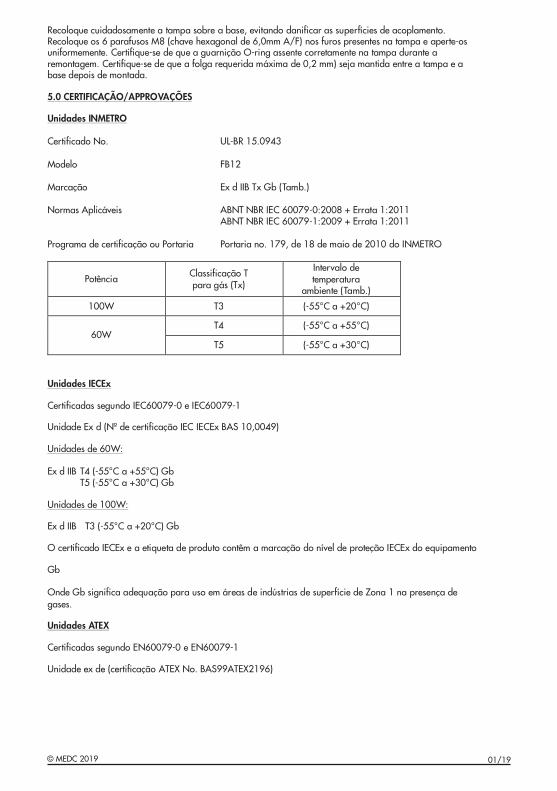
Recoloque cuidadosamente a tampa sobre a base, evitando danificar as superfícies de acoplamento. Recoloque os 6 parafusos M8 (chave hexagonal de 6,0mm A/F) nos furos presentes na tampa e aperte-os uniformemente. Certifique-se de que a guarnição O-ring assente corretamente na tampa durante a remontagem. Certifique-se de que a folga requerida máxima de 0,2 mm) seja mantida entre a tampa e a base depois de montada.
5.0 CERTIFICAÇÃO/APPROVAÇÕES
Unidades INMETRO
Certificado No. UL-BR 15.0943
Modelo FB12
Marcação Ex d IIB Tx Gb (Tamb.)
Normas Aplicáveis ABNT NBR IEC 60079-0:2008 + Errata 1:2011 ABNT NBR IEC 60079-1:2009 + Errata 1:2011
Programa de certificação ou Portaria Portaria no. 179, de 18 de maio de 2010 do INMETRO
Potência Classificação T para gás (Tx)
Intervalo de temperatura
ambiente (Tamb.)
100W T3 (-55°C a +20°C)
T4 (-55°C a +55°C)60W
T5 (-55°C a +30°C)
Unidades IECEx
Certificadas segundo IEC60079-0 e IEC60079-1
Unidade Ex d (Nº de certificação IEC IECEx BAS 10,0049)
Unidades de 60W:
Ex d IIB T4 (-55°C a +55°C) Gb T5 (-55°C a +30°C) Gb
Unidades de 100W:
Ex d IIB T3 (-55°C a +20°C) Gb
O certificado IECEx e a etiqueta de produto contêm a marcação do nível de proteção IECEx do equipamento
Gb
Onde Gb significa adequação para uso em áreas de indústrias de superfície de Zona 1 na presença de gases.
Unidades ATEX
Certificadas segundo EN60079-0 e EN60079-1
Unidade ex de (certificação ATEX No. BAS99ATEX2196)
© MEDC 2019 01/19

Ex d IIB T4 (-55°C a +55°C) Gb T5 (-55°C a +30°C) Gb
Unidades de 100W:
Ex d IIB T3 (-55°C a +20°C) Gb
O certificado ATEX e a etiqueta de produto contêm a marcação do grupo e da categoria ATEX:
II 2 G
Onde:
Significa a conformidade com as normas ATEX II Significa adequação para uso em indústrias de superfície 2 Significa adequação para uso em áreas de Zona 1 G Significa adequação para uso na presença de gases
Unidades de 60W:
BIIdEx (T4 - )C+55°aC55°(T5 - C+30°aC55°
:W001edsedadiUn
BIIdEx (T3 -55
uqiteaeXETAATodcaifitrceO
:W06edsedadiUn
bG)bG)C
bG)C+20°aC5°
odoçãcaramamêtncootoudorpedateu
TAATairogetcaadeopurgo :EX
uqiteaeXETAATodcaifitrceO
G2II
:edOn
adimrofonocaacifingSiII poãçauqedaacifingSi2 poãçauqedaacifingSiG poãçauqedaacifingSi
odoçãcaramamêtncootoudorpedateu
XETAATsamronsamocedaeicíffírepusedsairtsúdnimeosuarap
1anoZedsaerámeosuarapsesagedaçneserpanosuarap
TAATairogetcaadeopurgo :EX
O certificado ATEX e a etiqueta de produto também contêm a seguinte marcação:
Significa que a unidade está em conformidade com as diretivas europeias pertinentes, neste caso a Diretiva 94/9/CE, juntamente com o número do organismo notificado que emitiu o certificado de exame CE de tipo.
Estas unidades também dispõem das seguintes aprovações:
Proteção da entrada (IP66 e 67) BS EN 60598-1:1997
iteaeXETAATodcaifitrceO qu
átseedadinuaeuqacifingSijEC9/94/
ugesa mêtnocmébamtotoduoprdea teu
uesaviteridsamocedadimrofonocmeádifiidú
:ãoçacarmetniu
viteriDaosacetsen,setnenitrepsaieporii idECddifi
av
omocetnematnuj,EC9/94/
sidmébmattasedadinusattaEs
e6P6I(adartneadoãçetoPr
euqodacifitonomsinagroodoremúno
:seõçvaorpasetteniugessadmeõp
89506N ESB)76e - 19971:
ouitime pitedECemaxexedodacifitrce
.op
01/19 © MEDC 2019
© MEDC 2019 01/19
MEDC Ltd, Unit B, Sutton Parkway, Oddicroft Lane, Sutton in Ashfield, United Kingdom NG17 5FBTel: +44 (0)1623 444444 Fax: +44 (0)1623 444531Email: [email protected] [email protected]: www.medc.com
MEDC Stock No:TM339-ISS.A
01/19 © MEDC 2019


![SZ05-ZN/EN-A10€¦ · spring lever and withdraw filament 1. Pull filament guide tube out of filament intake, 2. Tap [Tools]. leave filament 10cm to pull filament easily. 5. Extruder](https://static.fdocuments.in/doc/165x107/5f8e7086182e8509724132b6/sz05-znen-a10-spring-lever-and-withdraw-filament-1-pull-filament-guide-tube-out.jpg)