Technical manual for ordering DORMA MANETTechnical manual for ordering and installation MANET...
48
DORMA Technical manual for ordering and installation MANET Single-point fixings for interior applications
Transcript of Technical manual for ordering DORMA MANETTechnical manual for ordering and installation MANET...

DORMA
Technical manualfor ordering and installation
MANETSingle-point fixingsfor interior applications

MANET Glass design system
2 07/04
Today’s approach to officedesign tends to be generouslyappointed, open-plan layouts.One of the basic underlyingprinciples in this regard isthat, in order to be effectivein business, you need a clearview of everything that ishappening.Consequently, flexible glasspartitions and doors are be-coming the preferred solutionfor internal spatial division.Thanks to the flexible modu-larity of the system, DORMAMANET offers architects andspecifiers a free hand increative almost bespokedesign with space, vision andlight as a foundation.
The basic component is thesingle-point fixing which iscountersunk into the glassand provides for a perfectlyflush finish in all applications.In addition to the counter-sunk version, however, thesystem now also offers a newalternative, i.e. whereby thesingle-point fixing is clam-ped to the glass surface.When using these mountingelements, glazing systems of 8 mm thickness as well asthe usual 10 and 12 mmthicknesses are available asstandard applications for sliding doors. Adjustableangle connectors provide for reliable attachment toexisting structural compo-nents or glass-to-glass combinations, with integra-ted pivoting and sliding doorelements complimenting thesystem.
Just as visually effective arethe MANET COMPACT stan-dardised sets from theDORMA MANET family.These facilitate single, fastplanning of the more popu-lar system types with 8, 10or 12 mm glass for doorsand 10 and 12 mm glass foroverpanels and side panels.Optional accessories areavailable for increased designvariety within the individualsets. The system compo-nents come with numerousadjustment possibilities inorder to ensure problem-freeinstallation of the sliding,double action or singleaction doors.Wall abutment profiles /connectors (for attaching the overpanel and side panelscreens to the existing structure) may need to be provided.
DORMA MANETAll the elements includingthe pull handles are availablein an elegant mock stainlesssteel finish (1.4305). In applications involving cor-rosive atmospheres, many fit-tings are also available instainless steel 1.4404.
Needless to say, all DORMAsystems are protected by proprietary rights worldwide. We will be glad to provide youwith information concerningrelevant patents, e.g.PCT/EP03/04299,PCT/EP01/04255 etc. onapplication.
Konstruktiver Glasbau e.V.
FachverbandKonstruktiver Glasbau e.V.
Fachverband

07/04 3
Single-point fixing 4 - 5
6 - 9
10 - 17
18 - 31
32 - 34
36 - 45
35
Page
Connection system
Pivoting door system
Sliding door system
Handle bars /door knobs
Installation tools /accessories
MANET COMPACT setsPivoting doorSliding door
Content
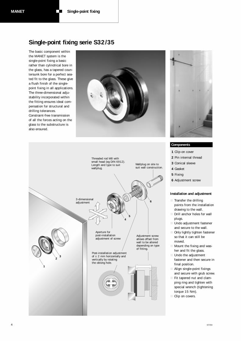
Transfer the drilling points from the installationdrawing to the wall.Drill anchor holes for wallplugs.Undo adjustment fastenerand secure to the wall. Only lightly tighten fastenerso that it can still bemoved. Mount the fixing and was-her and fit the glass. Undo the adjustmentfastener and then secure infinal position.Align single-point fixingsand secure with grub screw.Fit tapered nut and clam-ping ring and tighten withspecial wrench (tighteningtorque 15 Nm).Clip on covers.
Threaded rod M8 with small head (eg DIN 6912). Length and type to suit wallplug.
3-dimensionaladjustment
1
23
Wallplug on site to suit wall construction.
Installation and adjustment
45
6
Post-installation adjustment of ± 2 mm horizontally andvertically by rotating the oblong hole.
Aperture for post-installationadjustment of screw
Adjustment screwallows offset fromwall to be altereddepending on typeof fitting.
1 Clip-on cover
2 Pin internal thread
3 Conical sleeve
4 Gasket
5 Fixing
6 Adjustment screw
Components
MANET Single-point fixing
4 07/04
The basic component withinthe MANET system is thesingle-point fixing a basicrather than cylindrical bore inthe glass, has a tapered coun-tersunk bore for a perfect sea-ted fit to the glass. These givea flush finish of the single-point fixing in all applications.The three-dimensional adju-stability incorporated withinthe fitting ensures ideal com-pensation for structural anddrilling tolerances.Constraint-free transmissionof all the forces acting on theglass to the substructure isalso ensured.
Single-point fixing serie S32/35

07/04 5
Type and ordering information
Single-point fixing,Glass/WallGlass/Wall offsetadjustable 8.5 -11.5 mm
Complete fitting
Glass thickness 10 mm:Order No. 8.29.200.700.99
Glass thickness 12 mm:Order No. 8.29.210.700.99
Glass thickness 13.5 mm:Order No. 8.29.240.700.99
Glass thickness 15 mm:Order No. 8.29.244.700.99
Glass thickness 17.5 mm:Order No. 8.29.248.700.99
Ø 3
2
Ø 3
5
Single-point fixing,Glass/WallGlass/Wall offsetadjustable 11.5 -14.5 mm
Complete fitting
Glass thickness 10 mm:Order No. 8.29.201.700.99
Glass thickness 12 mm:Order No. 8.29.211.700.99
Glass thickness 13.5 mm:Order No. 8.29.241.700.99
Glass thickness 15 mm:Order No. 8.29.245.700.99
Glass thickness 17.5 mm:Order No. 8.29.249.700.99
Single-point fixing,Glass/WallGlass/Wall offsetadjustable 14.5 - 22 mm
Complete fitting
Glass thickness 10 mm:Order No. 8.29.202.700.99
Glass thickness 12 mm:Order No. 8.29.212.700.99
Glass thickness 13.5 mm:Order No. 8.29.242.700.99
Glass thickness 15 mm:Order No. 8.29.246.700.99
Glass thickness 17.5 mm:Order No. 8.29.250.700.99
Single-point fixing,Glass/WallGlass/Wall offset 6 mmnot adjustable
Complete fitting
Glass thickness 10 mm:Order No. 8.29.205.700.99
Glass thickness 12 mm:Order No. 8.29.215.700.99
Glass thickness 13.5 mm:Order No. 8.29.243.700.99
Glass thickness 15 mm:Order No. 8.29.247.700.99
Glass thickness 17.5 mm:Order No. 8.29.251.700.99
adjustable
Glass-thickness
Glass-thickness
Glass-thickness8.5-11.5
Ø 3
2
Ø 3
5
adjustable
11.5-14.5
Ø 3
2
Ø 3
5
adjustable
14.5-22.5
Ø 3
2
Ø 3
5
6
not adjustable
Glass-thickness

MANET Connection system
6 07/04
The system approach is verymuch in evidence in the caseof the interconnecting com-ponents. Elements such asclamping and angle connec-tors of various designs andalso interconnecting fastenersof various lengths can becombined in order to attachglass of different thicknessesat any required angle to thefloor, to ceilings, to walls andto plinth supports.Single-point fixings flush with the glass are also usedfor this interconnection andglass-to-glass system. Tolerances are compensatedby sloted holes in the inter-connecting fasteners.
1 2
3 4
3 ColumnCeiling/floor fixingOrder No. 8.21.146.700.99
4 Clamping connectorGlass thickness 8 -12 mmOrder No. 8.29.149.700.99
5Connecting rod
Length 52.5 mmOrder No. 8.21.301.002.40
Length 60 mmOrder No. 8.21.301.004.40
Length 82 mmOrder No. 8.21.301.003.40
Length 103 mmOrder No. 8.21.301.005.40
103 mm
82 mm
60 mm
52.5 mm
5
Ordering information
1 Pivoting glass clampGlass thickness 8-12 mmOrder No. 8.29.160.700.99
Glass thickn. 13.5-17.5 mmOrder No. 8.29.162.700.99
Glass thickn.17.5-21.5 mmOrder No. 8.29.163.700.99
2 Pivoting wall fixingOrder No. 8.21.141.700.99
Connection system
07/04 7
6
adjustable via oblong hole
1 2
5
87 Components and assembly of the glass fixing
3 4
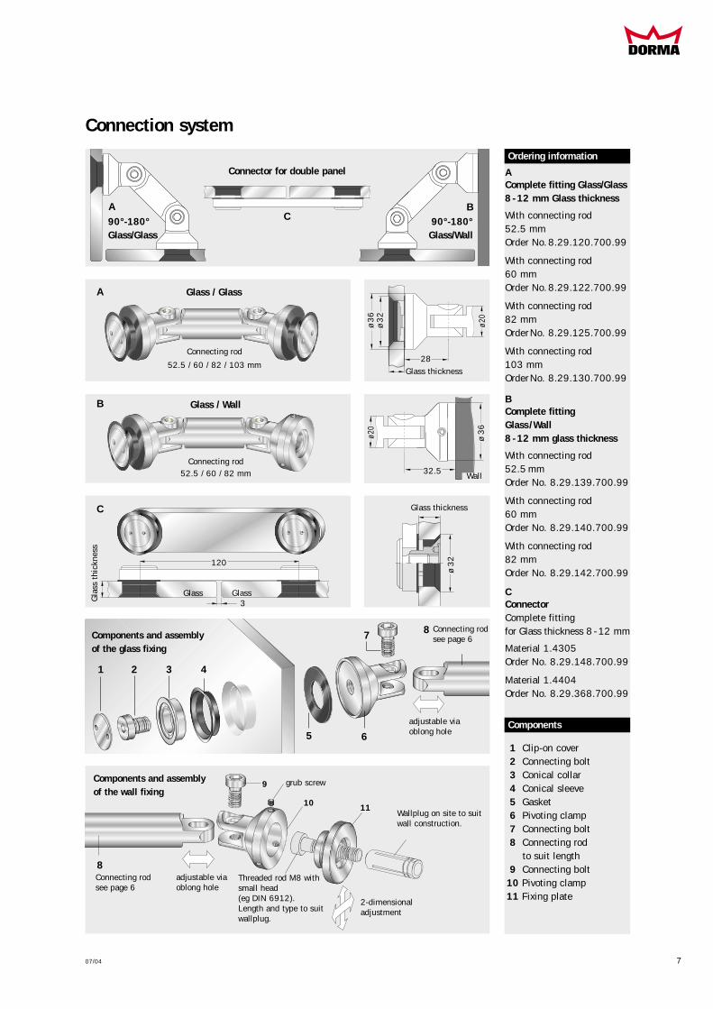
1 Clip-on cover2 Connecting bolt3 Conical collar4 Conical sleeve5 Gasket6 Pivoting clamp 7 Connecting bolt8 Connecting rod
to suit length9 Connecting bolt
10 Pivoting clamp11 Fixing plate
Ordering information
Complete fitting Glass/Glass8 -12 mm Glass thickness
With connecting rod52.5 mmOrder No.8.29.120.700.99
With connecting rod60 mmOrder No.8.29.122.700.99
With connecting rod82 mmOrderNo. 8.29.125.700.99
With connecting rod103 mmOrderNo. 8.29.130.700.99
A
A
A
Connecting rod
52.5 / 60 / 82 / 103 mm
ø20
28ø
36
ø3
2Glass thickness
Gla
ss t
hick
ness
Components
Complete fitting Glass /Wall8 -12 mm glass thickness
With connecting rod52.5 mmOrder No. 8.29.139.700.99
With connecting rod60 mmOrder No. 8.29.140.700.99
With connecting rod82 mmOrder No. 8.29.142.700.99
B
C
B
B
Connecting rod52.5 / 60 / 82 mm
Connecting rodsee page 6
Connecting rodsee page 6
Components and assemblyof the wall fixing
Threaded rod M8 withsmall head(eg DIN 6912).Length and type to suitwallplug.
adjustable via oblong hole
grub screw
2-dimensionaladjustment
Wallplug on site to suitwall construction.
ø20
ø 3
632.5
9
10 11
8
Wall
90°-180°Glass/Wall
Glass / Glass
Connector for double panel
Glass / Wall
90°-180°Glass/Glass
C
C
120
Glass Glass
ø 3
2
ConnectorComplete fittingfor Glass thickness 8 -12 mm
Material 1.4305Order No. 8.29.148.700.99
Material 1.4404Order No. 8.29.368.700.99
Glass thickness
Connection system
3

MANET Connection system
8 07/04
Ordering information
AClamping connector
Complete fittingGlass thickness 8 -12 mmOrder No. 8.29.149.700.99
BCorner connector 90°Glass/ceiling, Glass/floorconnection
Complete fittingGlass thickness 8 -12 mm(only supporting function) Order No. 8.29.145.700.99
CCeiling fixing(bearing function)
Complete fittingGlass thickness 8 -12 mmOrder No. 8.29.337.700.99
with clamping discOrder No. 8.29.338.700.99
1Connecting bolt
2Pivoting clamp
3Connecting bolt
4Gasket
5Pivoting clamp
6Fixing plate
7Column
A
A
B
B
C
C
28 28
ø3
6
ø2
0
Components / Installation
adjustable via oblong hole
1 2
3 4
4 5
Connecting rodor steel cable
6
7
2-dimensionaladjustment
Grub screw
Hanging glass from theceiling is permissiblewhere there is other sup-port for the glass sheet.
Wallplug onsite to suitwall con-struction.
Threaded rod M8 with small head (eg DIN 6912).Length and type to suitwallplug.
Components
Fixing with cheeseheadscrewDIN 7984 M10 x..., or oval-head wood screwDIN 7996 8 x... depending on ceilingfixing requirements andwallplug type (by others)
Height adjustmentvia grub screw
with clampingdisc
Single-pointcountersunk
Single-point fixing clamping disc
Single-point fixing countersunk
Clip-on cover
Connection system

07/04 9
Dimensions in mm
Glass preparation with a tolerance of max. ± 0.3 mmis recommended.
Ensure compliance with minimum glass/bore clearances as per glass manu-facturer recommendations
±0
.3
Gla
ss t
hick
ness
For ESG and VSG out of ESG.
Clamping connector
Corner connectorsGlass/Glass
Glass/Wall
max
. 800
±0.
3
max. 800 ±0.3
90°
3
3
Dim
ensi
on A
Dimension A
Dimension B
Dimension B
Connecting rod
Connecting rod
90°95°
100°105°110°115°120°125°130°135°180°
Angle A/B
52.5
A/B
60
A/B
82 103
Length of Connecting rod
75706662595552494744
80757167636056545148
96908581777369666360
A/B
50
Dimensions for 10 mmglass thickness (considerother glass thicknesses).
90°Angle A/B
52.5
A/B
60
A/B
82
Length of Connecting rod
67/65 72/70 87.5/86
Dimensions for 10 mmglass thickness (considerother glass thicknesses).
Plan view
Angle
150
60
28
28
28
28
32
.5
28
3
72
Countersunk holes for countersunk single-pointfixings
Recommended centres forfixed glazing element
Cylindrical bore for clamping disc single-point fixings
Cyl
indr
ical
bor
e
Glass preparation for single-point fixings and corner connections
Corner connector glass/ceiling Corner connector glass/floor
Corner connectors Glass/Glass 90° -180°
Corner connectors Glass/Wall 90 -180°
Ceiling fixing (bearing)
90°
ø 32+0.2
ø 26
Gla
ss t
hick
ness
ø 26+0.2
Ø1
5
28
3
AngleDim
ensi
on A
Dimension B
Wall
75
28
75
KS
Floor
Ceiling 41,5
Glass thickness
65
72
3
5
Decke
67
Connecting rod
3- 0
.2
Vertically adjust-ment ± 2.5

MANET Pivoting door system
10 07/04
MANET pivot (swing) doorsare used both in glass partiti-ons and in wall openings.They can be of either singleor double action design withweights up to max. 80 kg. Here, too, the single-pointfixings feature the new clip-on cover system for simpleinstallation. The "Variant 1" swing doorpivot assembly has beenmodified in its design so thatthe pivot point lies in theglass pane.
The air gap thus achievedreduces the nip hazard to aminimum. The clamp fittings can beadjusted to any location alongthe pivot rod, providing amajor advantage when itcomes to compensating forglass drilling tolerances.These pivot doors can beintegrated with ease in glasswall constructions throughthe use of system fanlightand side screen connectors.
Pivoting door system
Variant 3b
Pivot bearingshort type with intermediate tube
Variant 3a
Pivot bearingshort type
Variant 2
Pivot bearing withfull-length pivot rod
Variant 1
Pivot bearing withclamp fixingsand pivot point in the glass plane
Variant 1 Variant 2 and 3

07/04 11
Components pivoting door system suitable to Variant 1
A Sliding track tubeincl. endpiecestock length 3 mOrder No. 8.21.527.700.99fix length up to 6 mOrder No. 8.21.436.700.99
BOverpanel pivot bearing withlocation of stiffening pipe
for 10 mm glassOrder No. 8.29.404.700.99
for 12 mm glassOrder No. 8.29.405.700.99
CPT 25 Zapfenfor ceiling connection,15 mm Ø, with plugOrder No. 8.01.115.000.99
DPivot bearing for overpaneland ceiling connection
for 10 mm glassOrder No. 8.29.408.700.99
for 12 mm glassOrder No. 8.29.409.700.99
EClamp fixing horizontalsleeve type Order No. 8.29.150.700.99
Glass adapterfor clamp fixing
for 10 and 12 mm glassOrder No. 8.29.220.700.99
FPivot polefor pivot door with clamp fixing, prepared forpivot bearingOrder No. 8.29.237.700.99
GPivot bearingfor DORMA BTS/ Floor pivot
for 10 mm glassOrder No. 8.29.406.700.99
for 12 mm glassOrder No. 8.29.407.700.99
Ordering information
Glass thickness
3 m/6 m
Glass
thickness
Glass thickness
Glass thickn.
Fixing with grub screw
End-piece
Adjustable± 1.5
ø 46
ø46
ø46
28
28
55
25
77
77
77
28
28
12
3
Leng
thor
der-
rela
ted
ø 3
2
ø 3
5
ø 25
ø25
ø25
12
3
ø 25
ø 15
Sliding tracktube
A
B
C
D
E
F
G
Ceiling

Components pivoting door system suitable to Variant 2 and 3
A Overpanel/sidepanelconnector with pivot bearinglocation,Complete fittingfor 10 and 12 mm glassOrder No. 8.29.330.700.99Material 1.4404Order No. 8.29.362.700.99
B Pivot bearing for overpaneland ceiling connectionOrder No. 8.21.310.700.99Material 1.4404Order No. 8.21.350.700.99
C Pivot pole, (Variant 2), drilled, fix lengthOrder No. 8.21.300.700.99Material 1.4404Order No. 8.21.340.700.99
Single-point fixing, countersunk, fixed 1
for 10 and12 mm glassOrder No. 8.29.460.700.99Material 1.4404Order No. 8.29.461.700.99
for 13.5 -15.5 mm glassOrder No. 8.29.450.700.99
Single-point fixing, countersunk, centring 2
for 10 and 12 mm glassOrder No. 8.29.462.700.99Material 1.4404Order No. 8.29.463.700.99for 13.5 -15.5 mm glassOrder No. 8.29.455.700.99
Pivot pole set,top/bottom, shorttype incl. 4 single-point fixingsfor Variant 3a Order No. 8.29.302.700.99Material 1.4404Order No. 8.29.342.700.99for Variant 3bOrder No. 8.29.303.700.99Material 1.4404Order No. 8.29.343.700.99
Intermediate tube f. variant3bfix length up to 2 mOrder No. 8.21.305.700.99Material 1.4404Order No. 8.21.345.700.99
stock length 1.923 mmOrder No. 8.21.304.700.99Material 1.4404Order No. 8.21.344.700.99
D Pivot bearing for DORMA BTS/floor pivotOrder No. 8.21.311.700.99Material 1.4404Order No. 8.21.351.700.99
Ordering informationGlass
thickness
Variant 2 Variant 3a b
11
57
7
18.5
18.5
A
B
C
1
2
2
2
D
83
89
76
18.5
ø 25
ø32
12 07/04
Inte
rmed
iate
tub
e
MANET Pivoting door system
07/04 13
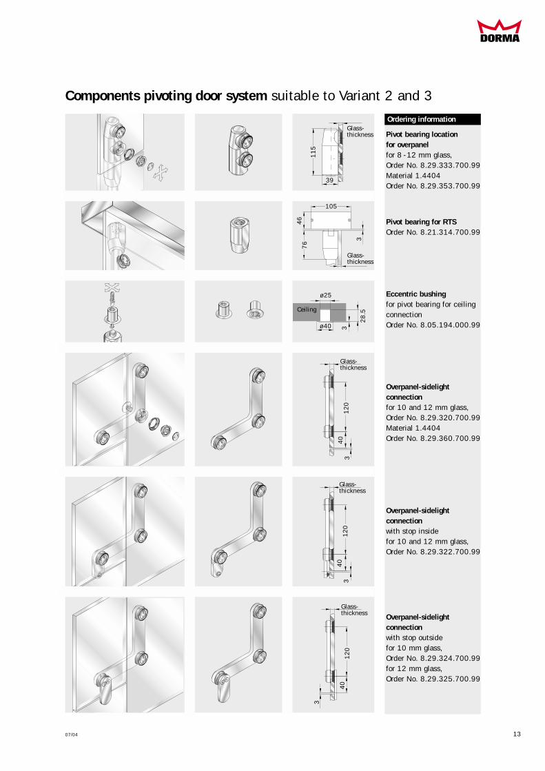
Components pivoting door system suitable to Variant 2 and 3
Ordering information
Pivot bearing locationfor overpanelfor 8 -12 mm glass,Order No. 8.29.333.700.99Material 1.4404Order No. 8.29.353.700.99
Pivot bearing for RTSOrder No. 8.21.314.700.99
Eccentric bushing for pivot bearing for ceilingconnectionOrder No. 8.05.194.000.99
Overpanel-sidelight connectionfor 10 and 12 mm glass,Order No. 8.29.320.700.99Material 1.4404Order No. 8.29.360.700.99
Overpanel-sidelight connectionwith stop insidefor 10 and 12 mm glass,Order No. 8.29.322.700.99
Overpanel-sidelight connectionwith stop outsidefor 10 mm glass,Order No. 8.29.324.700.99for 12 mm glass,Order No. 8.29.325.700.99
Ordering informationGlass-thickness
Glass-thickness
Glass-thickness
11
5
28
.5
12
04
0
39
ø40
ø25
Ceiling
33
Glass-thickness
12
04
03
Glass-thickness
12
04
0
3
46
3
105
76

Components pivoting door system suitable to variant 2 and 3
Overpanel/sidelight connector for glass fixing90° offset,with pivot bearing location,complete fittingfor 10 and 12 mm glass,A right handOrder No. 8.29.331.700.99B left handOrder No. 8.29.332.700.99
Overpanel/sidelight connector for wall fixing90° offset,with pivot bearing location,complete fittingfor 10 and 12 mm glass,C right handOrder No. 8.29.328.700.99D left handOrder No. 8.29.329.700.99
Overpanel/sidelight connector for wall fixing90° offset,complete fittingfor 10 and 12 mm glass,E left handOrder No. 8.29.327.700.99F right handOrder No. 8.29.326.700.99
Ordering information
A
C
A B
C D
E F
E
FB
D
14 07/04
Glass-thickn.
12
01
20
12
0
73
73.5
73.5
73.5
73.5
11
5
65
70 70
8
73
65 8
3
39.5
3 70 703 3
MANET Pivoting door system

07/04 15
Components pivoting door system (universally applicable)
Ordering information
Floor pivotOrder No. 8.01.106.700.99
Stop for pivot doorwith ceiling mountingOrder No. 8.21.334.700.99
Stop at overpanel(inside/outside)for 10 and 12 mm glass,Order No. 8.29.335.700.99
Corner lock top/bottomfor 8 -12 mm glass,Order No. 8.14.400.700.99
Corner lock top/bottomwith profile cylinder rose oninside for 8 -12 mm glass,Order No. 8.14.405.700.99
Profile cylinderfor corner lockOrder No. 8.14.206.000.99
A Eccentric bushingfor corner lockOrder No. 8.05.194.000.99B Bushing, plasticsOrder No. 8.00.110.133.32
C Strike plateOrder No. 8.05.190.000.99
Ordering information
Ceiling
Floor
Floor
Floor
32.5
15
5
Glass-thickness
Glass thickness
4040
39
30
30
65
ø 40
1221
94
65 mm
55 mm
32
10
(12
)m
m
65
mm
ø 25
Ø 15.5
73
7
7
3
63
11
3
28.5
92
A
B
C
Glass preparation
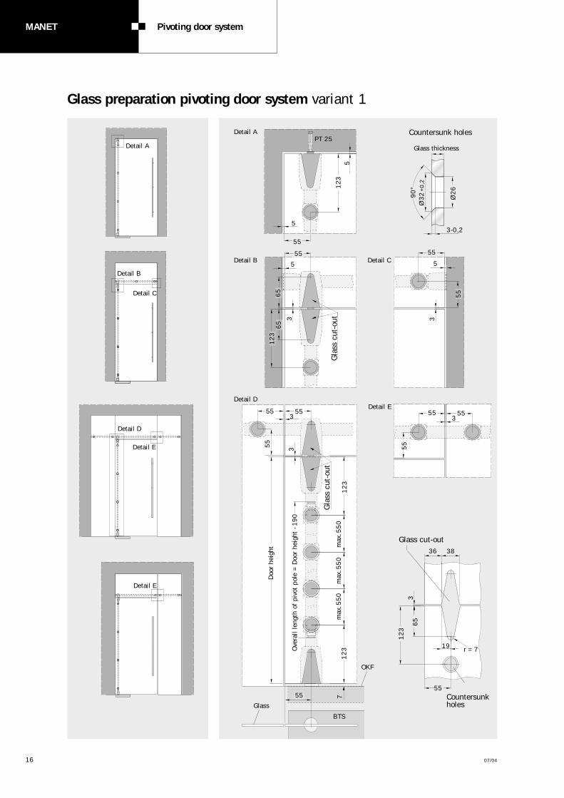
Glass preparation pivoting door system variant 1
16 07/04
MANET Pivoting door system
Glass cut-out
Countersunkholes
OKF
Countersunk holes
Glass thickness
3-0,2
Ø2
6
55
55 55
55 55
5565
65
12
3
12
3
90
°Ø
32
+0
,2
5
3
3
3
Gla
ss c
ut-o
ut
5
5 5
Detail A
Detail APT 25
Detail B Detail C
Detail D
Detail D
Detail E
Detail E
Detail E
36 38
55
19 r = 7
Detail C
Detail B
55
55
12
31
23O
vera
ll le
ngth
of
pivo
t po
le =
Doo
r he
ight
-1
90
Doo
r he
ight
12
3
65
max
.55
0m
ax.5
50
max
.55
0
55
55
55
3
3
3
7
Gla
ss c
ut-o
ut
Glass
BTS

Glass preparation pivoting door system variant 2 and 3
07/04 17
Detail A
Detail B
Detail C
Detail Bdoor to wall
Detail D
Detail D
Detail E
Detail E
Detail E with stop
Detail E
Detail A door to wall
Detail A door to sidelight
Detail Bdoor to glass
OKF
BTSGlass
Countersunk holes
Glass thickness
8
8 8
3
5
3-0,2
65
65
67
40
40
65
65
67 50
5
50
3
3
3
3
67 50
3
12
0
12
01
20
11
3
11
3X1
= ±
0,3 X2
= ±
0,3 X3
= ±
0,3
Ove
rall
leng
th o
f pi
vot
rod
= D
oor
heig
ht -
54
mm
89
18,5
24
765
703
70
65
Ø2
6
11
3
11
3
90
°Ø
32
+0
,2
50
3 33
40
11
31
20
4040
50
11
3
MANET Sliding door system
18 07/04
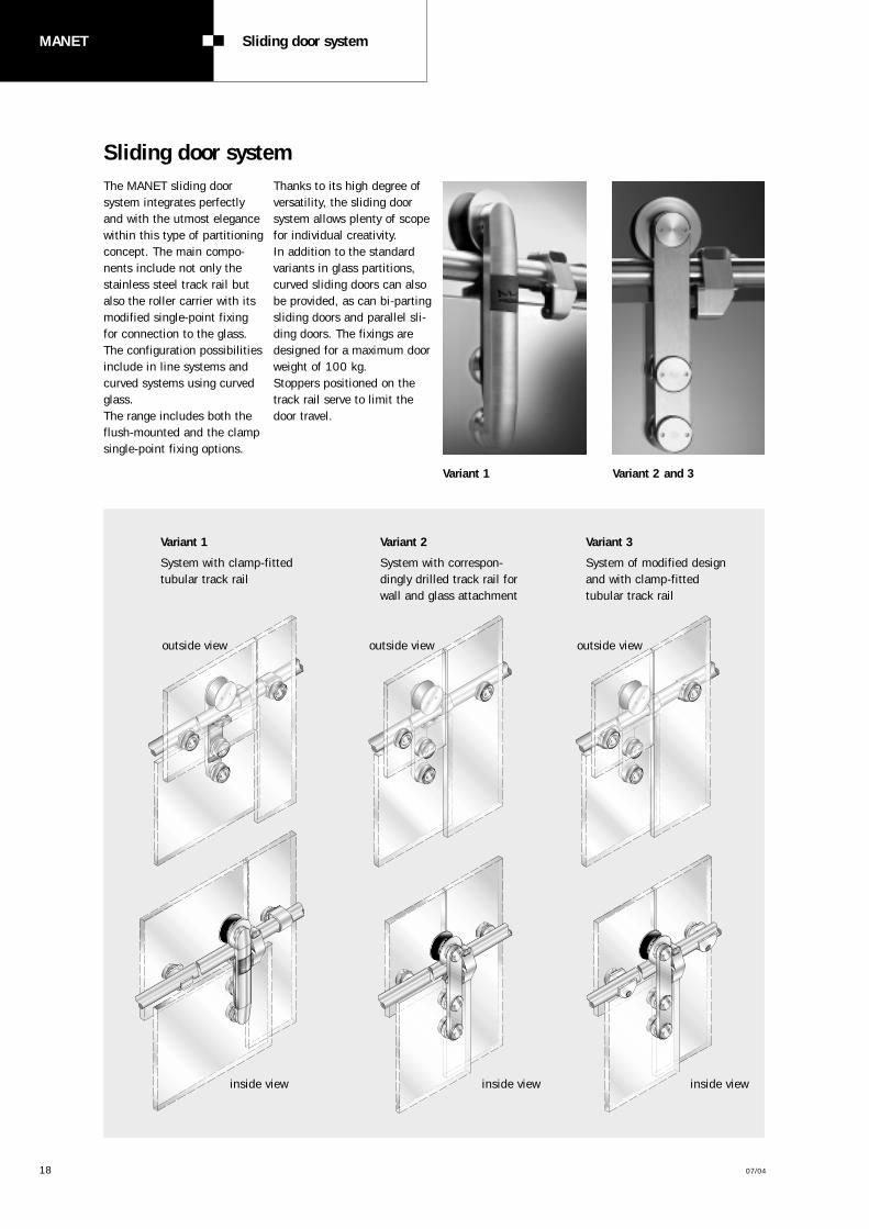
Variant 3
System of modified designand with clamp-fittedtubular track rail
Variant 2
System with correspon-dingly drilled track rail forwall and glass attachment
Variant 1
System with clamp-fitted tubular track rail
Variant 1 Variant 2 and 3
Sliding door systemThe MANET sliding doorsystem integrates perfectlyand with the utmost elegancewithin this type of partitioningconcept. The main compo-nents include not only thestainless steel track rail butalso the roller carrier with itsmodified single-point fixingfor connection to the glass.The configuration possibilitiesinclude in line systems andcurved systems using curvedglass.The range includes both theflush-mounted and the clampsingle-point fixing options.
Thanks to its high degree ofversatility, the sliding doorsystem allows plenty of scopefor individual creativity.In addition to the standardvariants in glass partitions,curved sliding doors can alsobe provided, as can bi-partingsliding doors and parallel sli-ding doors. The fixings aredesigned for a maximum doorweight of 100 kg.Stoppers positioned on thetrack rail serve to limit thedoor travel.
outside view outside view outside view
inside viewinside view inside view

07/04 19
Components sliding door system suitable to variant 1
A Clip-on cover
B Pin internal thread
C Conical sleeve
D Gasket
E Fixing with oblong hole
F Mounting adapter
G Sliding door cover
H Logo plate
I Antijump mechanism
J Sliding track tube
Components
Sliding door rollerwith antijump mechanismonly lug with rollerOrder No. 8.29.414.700.99
2 piece single-point fixing for sliding door roller:
countersunk f. 10 mm glassOrder No. 8.29.416.700.99
countersunk f. 12 mm glassOrder No. 8.29.417.700.99
Sliding track tubeincl. endpiece
stock length 3 mOrder No. 8.21.527.700.99Material 1.4404Order No. 8.21.530.700.99
fix length 6 mOrder No. 8.21.436.700.99Material 1.4404Order No. 8.21.532.700.99
Sliding track tubebent
max. curve length 2.6 mOrder No. 8.21.409.700.99
max. curve length 5.6 mOrder No. 8.21.413.700.99
Ordering information
3 m/6 m
Curve length
Note!Closed-type clamp mountings cannot be used with a curved tubular track.
r =
min
.600
mm
ø2
5
ø25
A
B
C
I
D E F G
H
J
23
27
.5Glassthickness
Glass thickness
Height-adjustment ± 2.5 mm
55
20
1
ø5
5
60
50
55
29
35

20 07/04
MANET Sliding door system
Components sliding door system suitable to variant 1
Ordering information
Wall adapterfor clamp fixingOrder No. 8.29.218.700.99
Glass adapterfor clamp fixingfor 10 and 12 mm glassOrder No. 8.29.220.700.99
Clamp horizontalsleeve type Order No. 8.29.150.700.99
Clamp horizontalopenOrder No. 8.29.151.700.99
Clamp vertikalsleeve typeOrder No. 8.29.152.700.99
Ceiling retainerfor sliding track tube,carrying functionOrder No. 8.29.500.700.99
Recommended distance of the fixing points see page 28/29
Ordering information
23
23
Glass-
thickness
60
32
ø3
5
Cylin
der s
crew
DIN
691
2 M
8 x.
..(A2
/A4)
ø3
5
ø 25
32
ø 25
32
10
0
ø 80
40
ø 25
ø25
ø 25
07/04 21
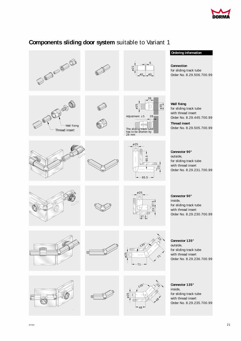
Components sliding door system suitable to Variant 1
Ordering information
Wall fixingfor sliding track tubewith thread insertOrder No. 8.29.445.700.99
Thread insertOrder No. 8.29.505.700.99
Connectionfor sliding track tubeOrder No. 8.29.506.700.99
Connector 90°outside,for sliding track tubewith thread insertOrder No. 8.29.231.700.99
Connector 90°inside,for sliding track tubewith thread insertOrder No. 8.29.230.700.99
Connector 135°outside,for sliding track tubewith thread insertOrder No. 8.29.236.700.99
Connector 135°inside,for sliding track tubewith thread insertOrder No. 8.29.235.700.99
Ordering information
85
.5
85.5
ø2
1
ø 25
23
ø2
5ø
25
135°
71
48
71
48
135°
ø3
5
ø2
5
40 40
5
39
28Adjustment ±5
The sliding track tubehas to be shorten by28 mm
Thread insertWall fixing
23
23
23
ø 25
37
.5
37.5

Components sliding door system suitable to variant 2
A Clip-on cover
B Cylinder screw
C Pin internal thread
D Conical sleeve
E Screw bolt
F Antijump mechanism
G Track
Components
Sliding door rollerwith antijump mechanism
only lug with rollerOrder No. 8.29.400.700.99Material 1.4404Order No. 8.29.401.700.99
2 piece single-point fixingfor sliding door roller:
countersunk f. 8 -12mm glassOrder No. 8.29.430.700.99Material 1.4404Order No. 8.29.431.700.99
clamping disc f. 8-12mm glassOrder No. 8.29.432.700.99
countersunk for 13.5 -17.5 mm glassOrder No. 8.29.435.700.99
countersunk f. 19 mm glassOrder No. 8.29.437.700.99
Track, drilled
for fixing on glass up to 6 mOrder No. 8.21.405.700.99Material 1.4404Order No. 8.21.456.700.99
for fixing on wallbup to 6 mOrder No. 8.21.406.700.99Material 1.4404Order No. 8.21.457.700.99
Connectorsincl. frontal preparation intracks,
for tracks 180°Order No. 8.21.404.700.99
offset for tracks 90 -180°Order No. 8.21.442.700.99
Ordering information
up to 6 m*
Angeled connection180°
ø2
5
CBA
E F G
D
22 07/04
MANET Sliding door system
The track rail is prefabricated per customerspecifications/drawing (see page 25) with allthe necessary drill holes already provided.
37.5
37
.5
ø5
5
55
19
8
Grub screw M5 x 6
18.5
27
.5
Glass-thickness
Glass thicknessHeight-
adjustment ± 2.5 mm
60
50
55
35
35
Angeled connection90 -180°
*max. single length 5 mm by coupling

07/04 23
Components sliding door system suitable to variant 2
1) Single-point fixing,track to glass,fixed, countersunk
for 10 and 12 mm glassOrder No. 8.29.460.700.99Material 1.4404Order No. 8.29.461.700.99
for 13.5 -15.5 mm glassOrder No. 8.29.450.700.99
for 17.5 mm glassOrder No. 8.29.451.700.99
fixed, clamping disc
for 10 and 12 mm glassOrder No. 8.29.465.700.99
centring, countersunk
for 10 and 12 mm glassOrder No. 8.29.462.700.99Material 1.4404Order No. 8.29.463.700.99
for 13.5 -15.5 mm glassOrder No. 8.29.455.700.99
for 17.5 mm glassOrder No. 8.29.456.700.99
centring, clamping disc
for 10 and 12 mm glassOrder No. 8.29.467.700.99
2) Flange fixing track to wallOrder No. 8.21.970.017.50
Material 1.4404Order No. 8.21.970.058.50
3) Flange fixing track to wall, adjustable Order No. 8.21.412.700.99
Wall fixing for trackroundOrder No. 8.21.441.700.99
Material 1.4404Order No. 8.21.466.700.99
flattenedOrder No. 8.21.440.700.99
Material 1.4404Order No. 8.21.465.700.99
Ceiling retainer for track
carrying functionOrder No. 8.21.315.700.99
Ordering information
2) Flange fixing track to wall
1) Countersunk single-point fixing,track to glass
ø 25Glass-
thickness
ø 25
18.5
35
16.5
60
30
Track rail detachment travel
ø 80
11
0
ø4
2
ø2
5
ø 25
ø 25
29
18.5
ø 25
3) Flange fixing track to wall, adjustable
Note:min. distanceglass zu wall 32 mm
2-dimensional adjustmentvia oblong hole
flattened
round
Recommended distance of the fixing points see page 28/29
Adjustment + 5 mm
ø5
5

Components sliding door system suitable to variant 3
A Clip-on cover
B Cylinder screw
C Pin internal thread
D Conical sleeve
E Screw bolt
G Sliding track tube
Components
Sliding door rollerwithout antijump mechanism
only lug with rollerOrder No. 8.29.402.700.99Material 1.4404Order No. 8.29.403.700.99
2 piece single-point fixings for sliding door roller:
countersunk f. 8 -12 m glassOrder No. 8.29.430.700.99Material 1.4404Order No. 8.29.431.700.99
clamping disk f.8-12mm glassOrder No. 8.29.432.700.99
countersunkfor 13.5 -17.5 mm glassOrder No. 8.29.435.700.99
countersunk f. 19 mm glassOrder No. 8.29.437.700.99
Ordering information
CBA
E G
D
24 07/04
MANET Sliding door system
3 m/6 m
ø2
5
Sliding track tubeincl. endpiece
Stock length 3 mOrder No. 8.21.527.700.99Material 1.4404Order No. 8.21.530.700.99
Fix length 6 mOrder No. 8.21.436.700.99Material 1.4404Order No. 8.21.532.700.99
Sliding track tubebent
max. curve length 2.6 mOrder No. 8.21.409.700.99
max. curve length 5.6 mOrder No. 8.21.413.700.99
18.5
27
.5
Glass-thickness
Glass thicknessHeight-
adjustment +1/ -2 mm
60
50
55
35
35
55
19
8
ø5
5
Curve length
r =
min
.600
mm
ø25
07/04 25
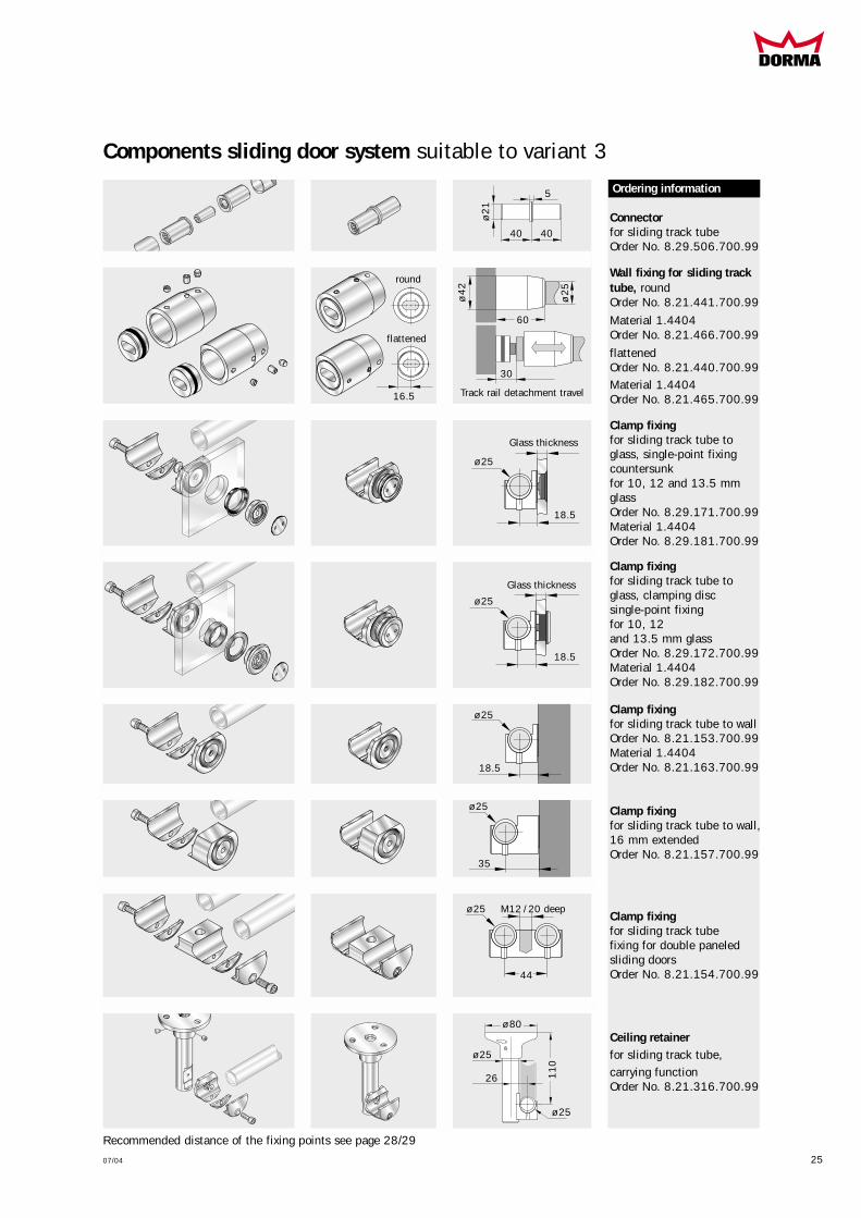
Components sliding door system suitable to variant 3
Ordering information
ø2
1
40 40
5
Wall fixing for sliding tracktube, roundOrder No. 8.21.441.700.99
Material 1.4404Order No. 8.21.466.700.99
flattenedOrder No. 8.21.440.700.99Material 1.4404Order No. 8.21.465.700.99
Clamp fixingfor sliding track tube toglass, single-point fixingcountersunk for 10, 12 and 13.5 mmglassOrder No. 8.29.171.700.99Material 1.4404Order No. 8.29.181.700.99
Clamp fixingfor sliding track tube toglass, clamping disc single-point fixing for 10, 12 and 13.5 mm glassOrder No. 8.29.172.700.99Material 1.4404Order No. 8.29.182.700.99
Clamp fixingfor sliding track tube to wallOrder No. 8.21.153.700.99Material 1.4404Order No. 8.21.163.700.99
Clamp fixingfor sliding track tube to wall,16 mm extended Order No. 8.21.157.700.99
Clamp fixingfor sliding track tubefixing for double paneledsliding doorsOrder No. 8.21.154.700.99
Connectorfor sliding track tubeOrder No. 8.29.506.700.99
ø 25
18.5
18.5
18.5
35
44
ø 25
ø 25
ø 25
ø 25 M12 / 20 deep
Glass thickness
Glass thickness
Ceiling retainer for sliding track tube,carrying functionOrder No. 8.21.316.700.99
ø 80
11
0
ø 25
ø 25
26
Recommended distance of the fixing points see page 28/29
16.5
60
30
Track rail detachment travel
ø4
2
ø2
5
flattened
round
26 07/04
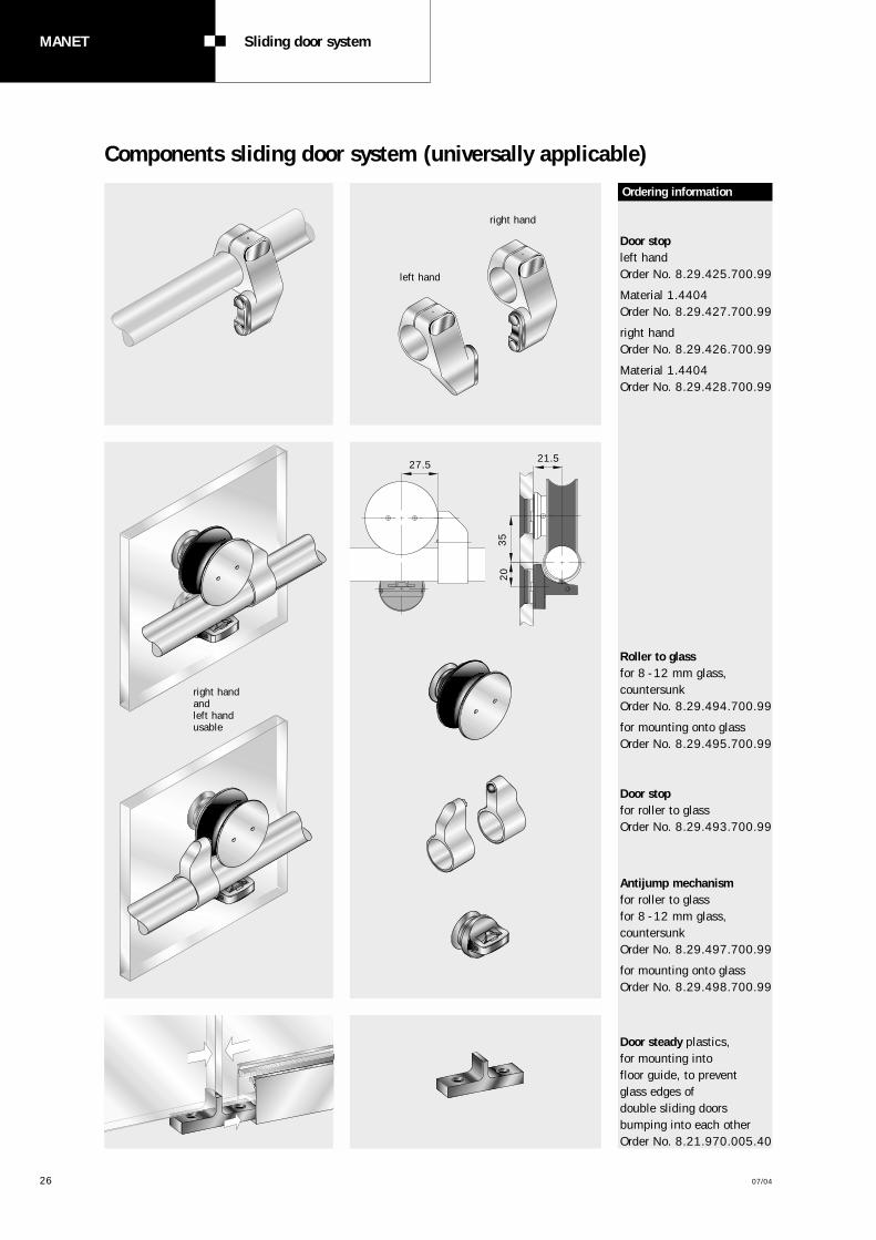
Components sliding door system (universally applicable)
MANET Sliding door system
Ordering information
Door stopleft handOrder No. 8.29.425.700.99
Material 1.4404Order No. 8.29.427.700.99
right handOrder No. 8.29.426.700.99
Material 1.4404Order No. 8.29.428.700.99
Roller to glassfor 8 -12 mm glass,countersunk Order No. 8.29.494.700.99
for mounting onto glassOrder No. 8.29.495.700.99
Antijump mechanismfor roller to glassfor 8 -12 mm glass,countersunkOrder No. 8.29.497.700.99
for mounting onto glassOrder No. 8.29.498.700.99
Door stop for roller to glassOrder No. 8.29.493.700.99
Door steady plastics,for mounting into floor guide, to prevent glass edges of double sliding doors bumping into each otherOrder No. 8.21.970.005.40
right hand andleft hand usable
left hand
right hand
27.521.5
35
20

Components sliding door system (universally applicable)
07/04 27
Ordering information
Aluminium brush profile
similar satin stainless steel
for 8 mm glassstock length 3 mOrder No. 8.07.402.113.99
fix length up to 6 mOrder No. 8.07.403.113.99
for 10 and 12 mm glassstock length 3 mOrder No. 8.07.400.113.99
fix length up to 6 mOrder No. 8.07.401.113.99
Sliding door lock with ratchet brace
for 8/10/12 mm glassOrder No. 8.21.447.700.99
Material 1.4404Order No. 8.21.446.700.99
Guide rail with brush sealsapplicable for 8/10/12 mm glassaluminium mill finishedfix length 6 mOrder No. 8.21.431.100.99
stock length 3 mOrder No. 8.21.432.100.99
Floor guideclamping disc,applicable for 8/10/12/13.5 mm glassOrder No. 8.07.326.000.99
13.5
37
.5
15.5for 8 mm glass
13.5for 10 mm glass
11.5for 12 mm glass
ø3
8
ø4
87
5
30
50
23
24
30
15
7

Supply and installation of the track rail
MANET Sliding door system
28 07/04
For rail support intervals on the glasswall or masonry, see fixing point inter-val recommendations per the table onthe next page.
Wall/single-point fixing clearancewhen using the wall connector(depends on stopper position).
Caution!Ensure that the stops/single-point fixings are positioned at locations appropriate
to the width of the door.
Required dimensions for the track production (here shown for variant 2)
G = Fixing point to glassW = Fixing point to wallK = ConnectionWK = Angle-connection
G
see table 50
100 see table
see table
Track length
max. 5000 with connector
* Note!Ensure that track joints and glass joints do not coincide
max. 5000 with angle-connector
max. 5000 with connector
3
3
min. 80
min
. 8
0
37.5
37
.5
18
.5
18.5
G W W
G G
G G GG
K K*
WK
G G G
100 100see table
see table see table see table
The track rail for the slidingdoor is prefabricated per thecustomer’s drawing and sup-plied complete with the glassand/or wall fixings required forthe specific application.(Fasteners for wall fixings tobe supplied by others.)Where the door is to be fittedto glass walls/partitions, it isof critical importance foraccurate fabrication that thefixing points provided coincidewith the drill holes (bores) inthe glass. The length toleran-ces must not exceed ± 0.3 mm.

see table
Sliding door Variant 3
07/04 29
Recommended distance of the track fixing points
1900
2000
2100
2200
2300
2400
2500
700 800 900 1000 1100 1200 1300 1400
Door width in mm
Glass thickn.mm
Doorheightin mm 8
770
750
730
710
690
680
660
10
710
700
680
660
640
630
610
12
670
650
640
620
610
590
580
Glass thickn.mm8
770
750
730
710
700
680
670
10
720
700
680
660
650
630
620
12
670
660
640
620
610
590
580
Glass thickn.mm8
770
750
730
710
700
680
670
10
710
690
680
660
650
630
620
12
670
650
640
620
610
590
580
Glass thickn.mm8
760
740
730
710
690
680
660
10
710
690
670
660
640
630
620
12
670
650
630
620
600
590
580
Glass thickn.mm8
760
740
720
700
690
670
660
10
700
680
670
650
640
620
610
12
660
640
630
610
600
590
580
Glass thickn.mm8
750
730
710
700
680
670
650
10
700
680
660
650
630
620
610
12
650
640
620
610
600
580
570
Glass thickn.mm8
740
720
710
690
680
660
650
10
690
670
660
640
630
610
600
12
650
630
620
600
590
580
570
Glass thickn.mm8
730
720
700
680
670
660
640
10
680
660
650
630
620
610
600
12
640
630
610
600
580
-
-
1900
2000
2100
2200
2300
2400
2500
700 800 900 1000 1100 1200 1300 1400
Door width in mm
Glass thickn.mm
Doorheightin mm 8
350
350
350
350
350
350
350
10
350
350
350
350
350
350
350
12
350
350
350
350
350
350
350
Glass thickn.mm8
400
400
400
400
400
400
400
10
400
400
400
400
400
400
400
12
400
400
400
400
400
400
400
Glass thickn.mm8
450
450
450
450
450
450
450
10
450
450
450
450
450
450
450
12
450
450
450
450
450
450
450
Glass thickn.mm8
500
500
500
500
500
500
500
10
500
500
500
500
500
500
490
12
500
500
500
490
480
470
460
Glass thickn.mm8
550
550
550
550
550
530
520
10
550
540
530
520
510
500
490
12
530
510
500
490
480
470
460
Glass thickn.mm8
600
580
570
550
540
530
520
10
550
540
530
510
500
490
480
12
520
510
500
480
470
460
450
Glass thickn.mm8
590
570
560
550
540
530
520
10
550
530
520
510
500
490
480
12
510
500
490
480
470
460
450
Glass thickn.mm8
580
570
560
540
530
520
510
10
540
530
520
500
490
480
470
12
510
500
490
470
460
-
-
1900
2000
2100
2200
2300
2400
2500
700 800 900 1000 1100 1200 1300 1400
Door width in mm
Glass thickn.mm
Doorheightin mm 8
610
600
580
560
550
540
530
10
570
550
540
520
510
500
490
12
530
520
510
490
480
470
460
Glass thickn.mm8
610
600
580
570
550
540
530
10
570
550
540
530
510
500
490
12
540
520
510
500
480
470
460
Glass thickn.mm8
610
590
580
570
550
540
530
10
570
550
540
530
510
500
490
12
530
520
510
490
480
470
460
Glass thickn.mm8
610
590
580
560
550
540
530
10
560
550
540
520
510
500
490
12
530
520
500
490
480
470
460
Glass thickn.mm8
600
590
570
560
550
530
520
10
560
540
530
520
510
500
490
12
530
510
500
490
480
470
460
Glass thickn.mm8
600
580
570
550
540
530
520
10
550
540
530
510
500
490
480
12
520
510
500
480
470
460
450
Glass thickn.mm8
590
570
560
550
540
530
520
10
550
530
520
510
500
490
480
12
510
500
490
480
470
460
450
Glass thickn.mm8
580
570
560
540
530
520
510
10
540
530
520
500
490
480
470
12
510
500
490
470
460
-
-
see table
Sliding door Variant 1 Sliding track tube
Sliding track tube
see table
Sliding door Variant 2 Track compact
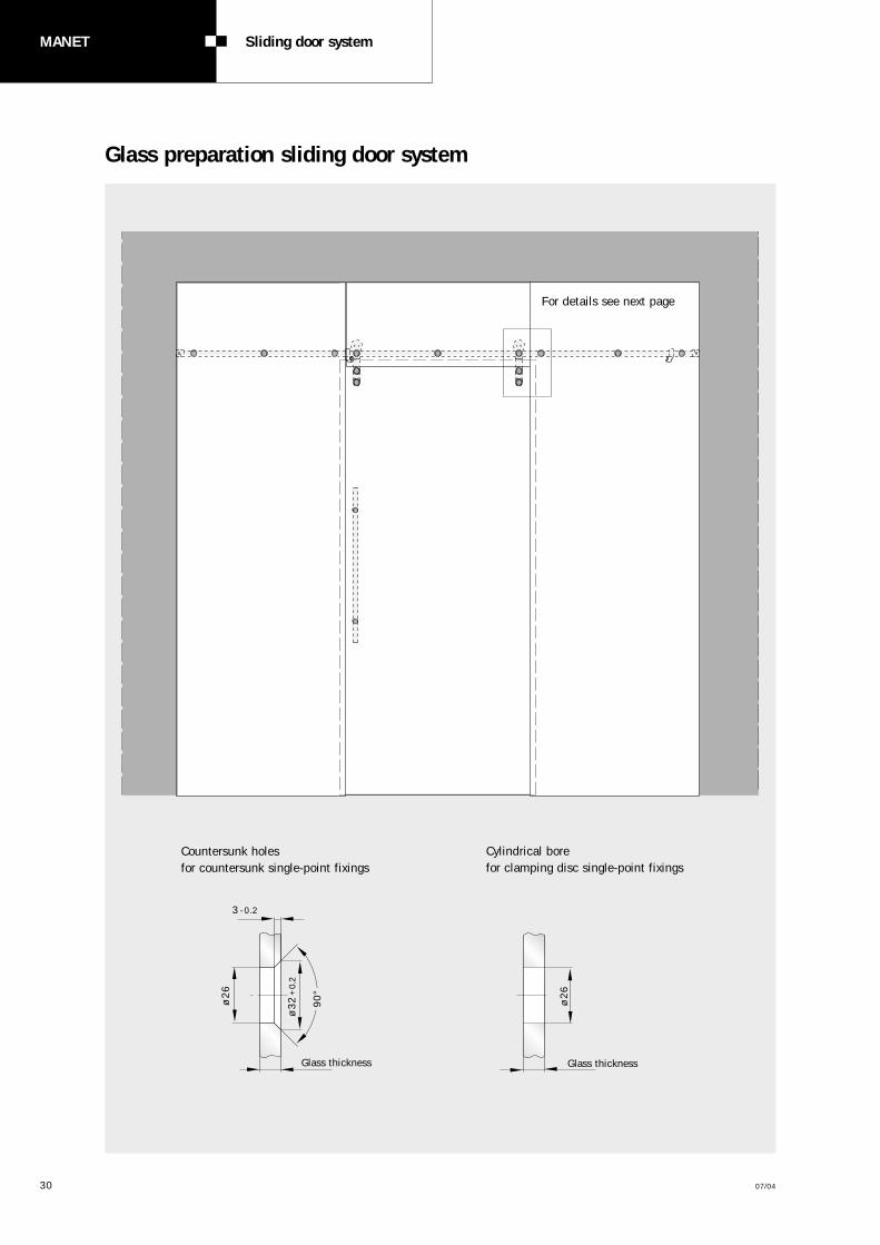
Glass preparation sliding door system
30 07/04
MANET Sliding door system
Countersunk holesfor countersunk single-point fixings
3 -0.2
Glass thickness Glass thickness
ø2
6
ø3
2+
0.2
ø2
6
90
°
Cylindrical borefor clamping disc single-point fixings
For details see next page

07/04 31
Glass preparation sliding door system
Sliding door Variant 3
Sliding door Variant 2
Sliding door Variant 1
27
.5
35
60
50
55
27
.5
18.5
35
35 6
0
50
55
27
.5
18.5
50 50
143
3
35
35 6
0
50
2
55
50 50
143
3
50 50
40
3
143
29
23
40
40
40

MANET Pull handle /knob system
32 07/04
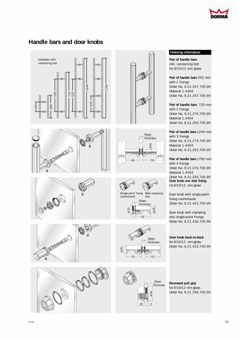
The pull handle/knob systemis designed for glass of 8, 10and 12 mm thick.The pull handles can be fixedto both sliding and pivoting(swing) doors on one faceusing the appropriate connec-tors or on both faces bythrough-bolting (back-to-backarrangement). The single-point fixings and throughbolts are included as standardequipment in the scope ofsupply.The pull handles can be fittedhorizontally, vertically or in ahandrail arrangement.
Handle bars and door knobs
Handle bars with single-pointfixings countersunkfor 8/10/12 mm glass
Handle bar 350 mmwith 2 fixingsOrder No. 8.29.268.700.99Material 1.4404Order No. 8.29.269.700.99
Handle bar 720 mmwith 2 fixingsOrder No. 8.29.271.700.99Material 1.4404Order No. 8.29.272.700.99
Handle bar 1240 mmwith 3 fixingsOrder No. 8.29.274.700.99Material 1.4404Order No. 8.29.275.700.99
Handle bar 1760 mmwith 4 fixingsOrder No. 8.29.277.700.99Material 1.4404Order No. 8.29.278.700.99
Handle bars with clampingdisc single-point fixingsfor 8/10/12 mm glass
Handle bar 350 mmwith 2 fixingsOrder No. 8.21.240.700.99Material 1.4404Order No. 8.21.280.700.99
Handle bar 720 mmwith 2 fixingsOrder No. 8.21.241.700.99Material 1.4404Order No. 8.21.281.700.99
Handle bar 1240 mmwith 3 fixingsOrder No. 8.21.242.700.99Material 1.4404Order No. 8.21.282.700.99
Handle bar 1760 mmwith 4 fixingsOrder No. 8.21.243.700.99Material 1.4404Order No. 8.21.283.700.99
Ordering information
Single-point fixingcountersunk
With clampingdisc
Complete withsingle-point fixings
ø3
2
ø1
6
45.5ø 25
Glass-thickness
35
0
15
0
52
0
52
0
52
0
12
40
17
60
72
0
07/04 33
Handle bars and door knobs
Pair of handle bars inkl. connecting bolt for 8/10/12 mm glass
Pair of handle bars 350 mmwith 2 fixingsOrder No. 8.21.267.700.99Material 1.4404Order No. 8.21.247.700.99
Pair of handle bars 720 mmwith 2 fixingsOrder No. 8.21.270.700.99Material 1.4404Order No. 8.21.250.700.99
Pair of handle bars 1240 mmwith 3 fixingsOrder No. 8.21.273.700.99Material 1.4404Order No. 8.21.253.700.99
Pair of handle bars 1760 mmwith 4 fixingsOrder No. 8.21.276.700.99Material 1.4404Order No. 8.21.256.700.99
Ordering information
Door knob one side fixingfor 8/10/12 mm glass
Door knob with single-pointfixing countersunkOrder No. 8.21.422.700.99
Door knob with clamping disc single-point fixingsOrder No. 8.21.426.700.99
Door knob back-to-back for 8/10/12 mm glassOrder No. 8.21.423.700.99
Complete withconnecting bolt
Single-point fixingcountersunk
With clampingdisc
Glass-thickness
ø1
6
45 70
ø 25ø 25
Glass-thickness
Glass-thickness
51
ø 3
2
ø2
5
ø2
5
51 51
35
0
15
0
52
0
52
0
52
01
24
0
17
60
72
0
Glass-thickness
ø 5
0
20 3
Recessed pull grip for 8/10/12 mm glassOrder No. 8.21.290.700.99

34 07/04
MANET Pull handle /knob system
Glass preparation handle bars and pull handle
Glass preparationhandle bars/pair of handle barsand knobs from page 32/33
at length of handle bars350 mm
Ordering information
ARCOS Pull handlefor 8/10/12 mm glassincl. connecting bolt
only in material 1.4404
Handle 350 mmwith 2 fixingsOrder No. 8.26.500.700.99
Handle 750 mmwith 2 fixingsOrder No. 8.26.510.700.99
Countersunk boreon handle bar and door knob, one side fixing
3 -0.2
Glass thickness
ø2
6
ø3
2+
0.2
90
°
Cylindrical bore on pair of handle barand door knobs, back-to-back
15
60
mm
±0
.310
40
mm
±0
.3
52
0 m
m ±
0.3
15
0 m
m ±
0.3
min. approx. 65
min. approx. 65
ø16
ø16
80
Glass thickness
Cylindrical bore
Connectingbolt
39
8/8
24
mm
75
0/3
50
mm
dri
ll ho
le c
entr
es
~ 6585
Bushing
Grub screw
Glass-thickness
ARCOS Pull handle
Recessed pull grip
Glass-
thickness
ø2
2
Glass-
thickness
ø3
8
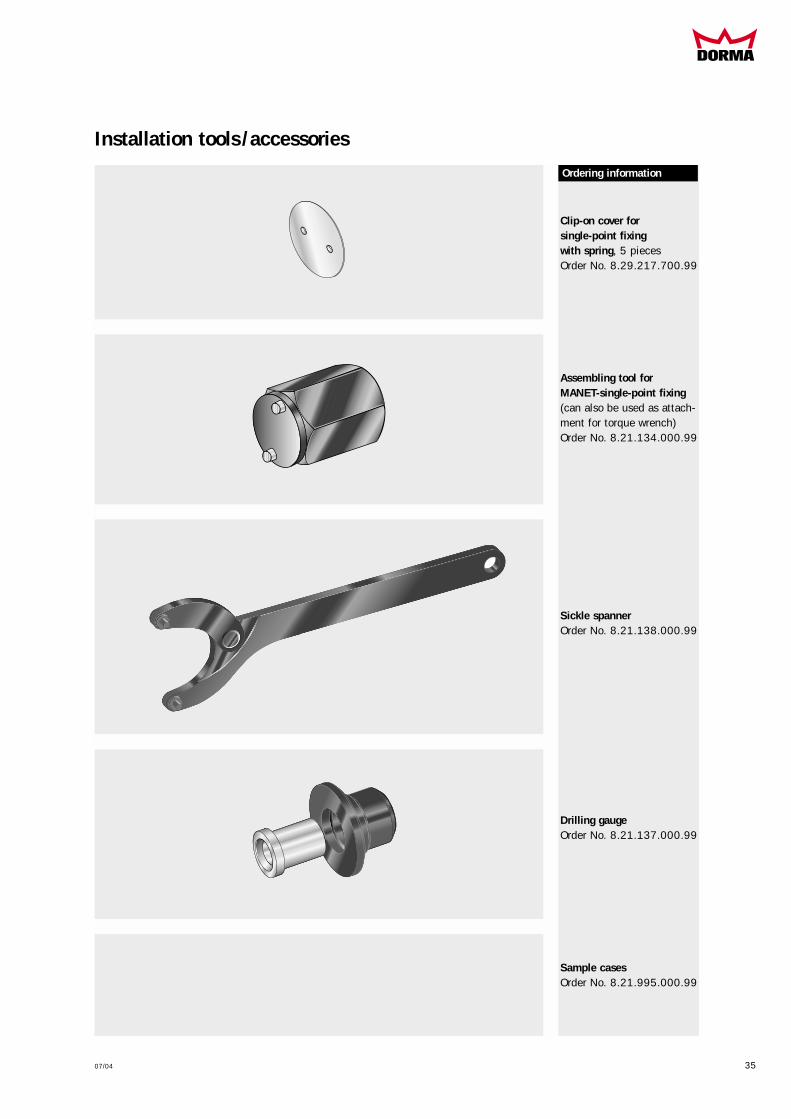
Installation tools /accessories
07/04 35
Ordering information
Clip-on cover for single-point fixing with spring, 5 piecesOrder No. 8.29.217.700.99
Assembling tool forMANET-single-point fixing(can also be used as attach-ment for torque wrench)Order No. 8.21.134.000.99
Sickle spannerOrder No. 8.21.138.000.99
Drilling gaugeOrder No. 8.21.137.000.99
Sample casesOrder No. 8.21.995.000.99

Pivot doorsset 1page 37
Pivot doorsset 2page 38
Pivot doorsset 3page 39
Pivot doors set 2 + 3page 38/39
Sliding doorsSet 4/5/6page 40 - 45
MANET COMPACT sets
Construction 5 (2 sets) Construction 6 (2 sets) Construction 7 (2 sets) Construction 8 (2 sets)
Construction 1 (1 set) Construction 2 (1 set) Construction 3 (1 set) Construction 4 (1 set)
The aesthetic elegance of theMANET COMPACT concept isalso available in the form ofstandardised sets for simple,fast planning of the morepopular system types with 8,10 or 12 mm toughenedsafety glass (TSG).Optional accessories enablethe individual sets to besemi-customised.
The system components offernumerous adjustment possi-bilities in order to ensureproblem-free installation ofwhichever door type – slidingor swing, single action ordouble action – is required.Wall abutment profiles mayneed to be provided (byothers) for fixing fan lightsand side screens.
Construction 9 (1 set) Construction 12 (1 set) Construction 18 (2 sets)
Construction set 4.1/4.2 Construction set 5.1/5.2 Construction set 6.1/6.2
Construction 13 (1 set) Construction 15 (1 set) Construction 23 (2 sets)
Construction 21 (every 1 set)
36 07/04
MANET COMPACT sets

07/04 37
Set 1
Ordering information
Set 1 consisting of: Pivot pole pair top/bottom, short type,
including:4 Single-point fixing for pivot pole,1 Pivot fitting top,1 Eccentric bushing f. pivot bearing top,1 Pivot fitting bottom
for DORMA BTS/floor pivot
Order No. 8.29.910.700.99
Order No. 8.29.911.700.99
Option: Set 1, but with additional intermediate tube for pivot pole pairin fix length
Options for SET 1
Handle bars Length 350 mmLength 720 mmLength 1240 mmLength 1760 mm
Pair of handle bars Length 350 mmLength 720 mmLength 1240 mmLength 1760 mm
Stop for pivot door with ceiling mounting
Ceiling fixing (bearing function)
Corner lock top/bottom
Corner lock top/bottom with rose on one lockside
Profile cylinder for corner lock 8.14.400/405.700.99
Eccentric bushing for corner lock 8.14.400/405.700.99
Floor pivot
Assembling tool for MANET-single-point f.
Sickle spanner
5 pcs. clip-on cover f. single-point fixingswith spring
Sample cases MANET COMPACTfor advice and presentation
Order No. 8.29.268.700.99Order No. 8.29.271.700.99Order No. 8.29.274.700.99Order No. 8.29.277.700.99
Order No. 8.21.267.700.99Order No. 8.21.270.700.99Order No. 8.21.273.700.99Order No. 8.21.276.700.99
Order No. 8.21.334.700.99
Order No. 8.29.337.700.99
Order No. 8.14.400.700.99
Order No. 8.14.405.700.99
Order No. 8.14.206.000.99
Order No. 8.05.194.000.99
Order No. 8.01.106.700.99
Order No. 8.21.134.000.99
Order No. 8.21.138.000.99
Order No. 8.29.217.700.99
Order No. 8.21.994.700.99
S8
S8
Pivot door MANET COMPACT without overpanel for 10 -12 mm glass
Set 1with pivot pole pairshort type
For the requisite glass preparationplease see 16/17
3 A
ir
15
01
13
65
Ceiling
7 A
ir
Airto sidelight 5to wall 8
Door weight 80 kg
Door height2500 mm
Door width1200 mm
15
01
13
65
DORMABTS
Panel height _________ mm – 577 mm= Length intermed. tube_________ mm
Please mention absolutely:

38 07/04
MANET COMPACT sets
Set 2
Ordering information
Set 2 consisting of: Pivot pole pair top/bottom, short type,
including:4 Single-point fixing for pivot pole,1 Pivot fitting top,1 Pivot bearing location for overpanel1 Pivot fitting bottom
for DORMA BTS/floor pivot
Order No. 8.29.912.700.99
Order No. 8.29.913.700.99
Option: Set 2, but with additional intermediate tube for pivot pole pairin fix length
Options for SET 2
Handle bars Length 350 mmLength 720 mmLength 1240 mmLength 1760 mm
Pair of handle bars Length 350 mmLength 720 mmLength 1240 mmLength 1760 mm
Stop for pivot door with ceiling mounting
Ceiling fixing (bearing function)
Stop at overpanel, (inside/outside)for 10 and 12 mm glass
Corner lock top/bottom
Corner lock top/bottom with rose on one lockside
Profile cylinder for corner lock 8.14.400/405.700.99
Eccentric bushing for corner lock 8.14.400/405.700.99
Overpanel-sidel. conn. for 10/12 mm glass
Overp.-sidel. conn. with stop inside for10 and 12 mm glass
Overp.-sidel. conn. with stop outside for 10 mm glassfor 12 mm glass
Floor pivot
Assembling tool for MANET-single-point f.
Sickle spanner
5 pcs. clip-on cover f. single-point fixingswith spring
Sample cases MANET COMPACTfor advice and presentation
Order No. 8.29.268.700.99Order No. 8.29.271.700.99Order No. 8.29.274.700.99Order No. 8.29.277.700.99
Order No. 8.21.267.700.99Order No. 8.21.270.700.99Order No. 8.21.273.700.99Order No. 8.21.276.700.99
Order No. 8.21.334.700.99
Order No. 8.29.337.700.99
Order No. 8.29.335.700.99
Order No. 8.14.400.700.99
Order No. 8.14.405.700.99
Order No. 8.14.206.000.99
Order No. 8.05.194.000.99
Order No. 8.29.320.700.99
Order No. 8.29.322.700.99
Order No. 8.29.324.700.99Order No. 8.29.325.700.99
Order No. 8.01.106.700.99
Order No. 8.21.134.000.99
Order No. 8.21.138.000.99
Order No. 8.29.217.700.99
Order No. 8.21.994.700.99
Pivot door MANET COMPACT with overpanel for 10 -12 mm glass
Set 2with pivot pole pairshort type
For the requisite glass preparationplease see page 16/17
3 A
ir
Wal
l
15
01
13
65
Overpanel
7 A
ir
Air towall 8
Door weight 80 kg
Door height 2500 mm
Door width1200 mm
15
01
13
65
DORMABTS
Panel height _______ mm – 577 mm= Length intermed. tube_______ mm
Please mention absolutely:

07/04 39
Set 3
Ordering information
Set 3 consisting of: Pivot pole pair top/bottom, short type,
including:4 Single-point fixing for pivot poles,1 Pivot fitting top,1 Overpanel-sidelight connector with
pivot bearing location,1 Pivot fitting bottom
for DORMA BTS/floor pivot
Order No. 8.29.914.700.99
Order No. 8.29.915.700.99
Option: Set 3, but with additional intermediate tube for pivot pole pairin fix length
Options for SET 2
Handle bars Length 350 mmLength 720 mmLength 1240 mmLength 1760 mm
Pair of handle bars Length 350 mmLength 720 mmLength 1240 mmLength 1760 mm
Stop for pivot door with ceiling mounting
Ceiling fixing (bearing function)
Stop at overpanel, (inside/outside)for 10 and 12 mm glass
Corner lock top/bottom
Corner lock top/bottom with rose on one lockside
Profile cylinder for corner lock 8.14.400/405.700.99
Eccentric bushing for corner lock 8.14.400/405.700.99
Overpanel-sidel. conn. for 10/12 mm glass
Overpanel-sidel. conn. with stop inside for10 and 12 mm glass
Overpanel-sidel. conn. with stop outside for 10 mm glassfor 12 mm glass
Floor pivot
Assembling tool for MANET-single-point f.
Sickle spanner
5 pcs. clip-on cover f. single-point fixingswith spring
Sample cases MANET COMPACTfor advice and presentation
Order No. 8.29.268.700.99Order No. 8.29.271.700.99Order No. 8.29.274.700.99Order No. 8.29.277.700.99
Order No. 8.21.267.700.99Order No. 8.21.270.700.99Order No. 8.21.273.700.99Order No. 8.21.276.700.99
Order No. 8.21.334.700.99
Order No. 8.29.337.700.99
Order No. 8.29.335.700.99
Order No. 8.14.400.700.99
Order No. 8.14.405.700.99
Order No. 8.14.206.000.99
Order No. 8.05.194.000.99
Order No. 8.29.320.700.99
Order No. 8.29.322.700.99
Order No. 8.29.324.700.99Order No. 8.29.325.700.99
Order No. 8.01.106.700.99
Order No. 8.21.134.000.99
Order No. 8.21.138.000.99
Order No. 8.29.217.700.99
Order No. 8.21.994.700.99
Pivot door MANET COMPACT with overpanel and sidelight for 10 -12 mm glass
Set 3with pivot pole pair,short type
For the requisite glass preparationplease see page 16/17
3 A
ir
3 Air
Sid
elig
ht
15
01
13
65
Overpanel
7 A
ir
Air towall 8
Door weight 80 kg
Door height 2500 mm
Door width1200 mm
15
01
13
65
DORMABTS
Panel height ________ mm – 577 mm= Length intermed. tube_________ mm
Please mention absolutely:

40 07/04
MANET COMPACT sets
Set 4.1 / 4.2
Sliding door MANET COMPACT for installation to wall, for 8 -12 mm glass
For the requisite glass preparationplease see page 30/31
60
143
143143
Doo
r he
ight
max
. 2
50
0 m
m
85
40 40
DGB
LM
TB = LM + 80 mm
Fix length: LL = 4 * X +286 mm
X XX X
Note:Door weight max. 100 kg
Set 4.1 with single-point fixings countersunk
Set 4.2 with clamping disc single-point fixings
LM = Daylight opening 880 - 1280 mmTB = Door width 960 - 1360 mmDGB = Entry width LM - 130 mmLL = Sliding track tube length X = Distance of single-point fixings
(LM –148) * 1/2

07/04 41
Set 4.1 / 4.2
Set 4.1 / Set 4.2 consisting of sliding track tube with end plugs in fix length(please indicate length when ordering,for calculation see page 28/29)
including:5 Clamp fixing
for track to wall2 Sliding door roller
incl. single-point fixing for 8 -12 mm glass1 Door stop left hand1 Door stop right hand1 Floor guide AGILEInstallation tools
Set as above, but with 16 mm extended clamp fixing
Order No. 8.29.917.700.99
Options for Set 4.1 / Set 4.2
Handle bars Length 350 mmLength 720 mmLength 1240 mmLength 1760 mm
Pair of handle bars Length 350 mmLength 720 mmLength 1240 mmLength 1760 mm
Door knobback-to-back for 8 - 12 mm glass
Door knobone side fixing for 8 - 12 mm glass
Corner lock top/bottom
Corner lock top/bottom with rose on one lockside
Profile cylinder for corner lock 8.14.400/405.700.99
Eccentric bushing for corner lock 8.14.400/405.700.99
Aluminium guide railLength 3000 mm
Assembling tool for MANET-single-point fixing
Sickle spanner
5 pcs. clip-on cover f. single-point fixings with spring
Sample cases MANET COMPACTfor advice and presentation
Order No. 8.21.240.700.99Order No. 8.21.241.700.99Order No. 8.21.242.700.99Order No. 8.21.243.700.99
Order No. 8.21.267.700.99Order No. 8.21.270.700.99Order No. 8.21.273.700.99Order No. 8.21.276.700.99
Order No. 8.21.423.700.99
Order No. 8.29.422.700.99
Order No. 8.14.400.700.99
Order No. 8.14.405.700.99
Order No. 8.14.206.000.99
Order No. 8.05.194.000.99
Order No. 8.21.432.700.99
Order No. 8.21.134.000.99
Order No. 8.21.138.000.99
Order No. 8.29.217.700.99
Order No. 8.21.994.700.99
Sliding door MANET COMPACT for installation to wall, for 8 -12 mm glass
Set 4.1with single-point fixingscountersunk
Set 4.2with clamping discsingle-point fixings
Ordering information
Order No. 8.29.926.700.99
Order No. 8.29.268.700.99Order No. 8.29.271.700.99Order No. 8.29.274.700.99Order No. 8.29.277.700.99
Order No. 8.21.267.700.99Order No. 8.21.270.700.99Order No. 8.21.273.700.99Order No. 8.21.276.700.99
Order No. 8.29.925.700.99
Order No. 8.29.916.700.99

42 07/04
MANET COMPACT sets
Set 5.1 / 5.2
Sliding door MANET COMPACT for installation to glass, one side attached to masonry, for 8 -12 mm glass
For the requisite glass preparationplease see page 30/31
60
143
50
50
30
143143
Doo
r he
ight
max
. 2
50
0 m
m
70
40
DGB = LM–100 mm
LM
TB = LM + 40 mm
Fix length: LL = 2 * X + 2 * Y + 360 mm
OB = LM–3 mm
Loop 3 mm
SB min. = LM–60 mm
X X Y Y
Note:Door weight max. 100 kg
Sliding door
SidelightOverpanel
Set 5.1 with single-point fixings countersunk
Set 5.2 with clamping disc single-point fixing
LM = Daylight opening 700 -1320 mmTB = Door width 740 -1360 mmDGB = Entry width 600 -1220 mmSBmin. = min. Side panel widthLL = Sliding track tube length X = Centre distance
between single-point fixingsoverlight (OB - 193) * 1/2
Y = Centre distance between single-point fixingssidelightY = X–29
OB = Overpanel width

07/04 43
Set 5.1 / 5.2
Set 5.1 / Set 5.2 consisting of sliding track tube with end plugs in fix length(please indicate length when ordering,for calculation see page 28/29)
including:6 Clamp fixing
fixing to glass, countersunk2 Sliding door roller
incl. single-point fixing for 8 -12 mm glass1 Wall fixing flattened1 Door stop left hand1 Door stop right hand1 Floor guide AGILEInstallation tools
Order No. 8.29.919.700.99
Options for Set 5.1 / Set 5.2
Handle bars Length 350 mmLength 720 mmLength 1240 mmLength 1760 mm
Pair of handle bars Length 350 mmLength 720 mmLength 1240 mmLength 1760 mm
Door knobback-to-back for 8 - 12 mm glass
Door knobone side fixing for 8 - 12 mm glass
Corner lock top/bottom
Corner lock top/bottom with rose on one lockside
Profile cylinder for corner lock 8.14.400/405.700.99
Eccentric bushing for corner lock 8.14.400/405.700.99
Aluminium guide railLength 3000 mm
Ceiling connector(bearing function)
Assembling tool for MANET-single-point fixing
Sickle spanner
5 pcs. clip-on cover f. single-point fixings with spring
Sample cases MANET COMPACTfor advice and presentation
Order No. 8.21.240.700.99Order No. 8.21.241.700.99Order No. 8.21.242.700.99Order No. 8.21.243.700.99
Order No. 8.21.267.700.99Order No. 8.21.270.700.99Order No. 8.21.273.700.99Order No. 8.21.276.700.99
Order No. 8.21.423.700.99
Order No. 8.29.422.700.99
Order No. 8.14.400.700.99
Order No. 8.14.405.700.99
Order No. 8.14.206.000.99
Order No. 8.05.194.000.99
Order No. 8.21.432.700.99
Order No. 8.29.337.700.99
Order No. 8.21.134.000.99
Order No. 8.21.138.000.99
Order No. 8.29.217.700.99
Order No. 8.21.994.700.99
Sliding door MANET COMPACT for installation to glass,one side attached to masonry, for 8 -12 mm
Set 5.1with single-point fixingscountersunk
Set 5.2with clamping discsingle-point fixings
Ordering information
Order No. 8.29.268.700.99Order No. 8.29.271.700.99Order No. 8.29.274.700.99Order No. 8.29.277.700.99
Order No. 8.21.267.700.99Order No. 8.21.270.700.99Order No. 8.21.273.700.99Order No. 8.21.276.700.99
Order No. 8.29.918.700.99

44 07/04
MANET COMPACT sets
Set 6.1 / 6.2
Sliding door MANET COMPACT for installation to glass, sidelight back-to-back, for 8 -12 mm glass
For the requisite glass preparationplease see page 30/31
60
143
50
5050
143143
Doo
r he
ight
max
. 2
50
0 m
m
70
4040
DGB = LM–100 mm
LM
TB = LM + 80 mm
Fix length: LL = 2 * X + 2 * Y + 460 mm
OB = LM–6 mm
Loop 3 mmLoop 3 mm
SB min. = LM–20 mm
X X Y Y
Note:Door weight max. 100 kg
Sliding door
SidelightSide-light
Overpanel
Set 6.1 with single-point fixings countersunk
Set 6.2 with clamping disc single-point fixings
LM = Daylight opening 700 -1320 mmTB = Door width 740 -1360 mmDGB = Entry width 600 -1220 mmOB = Overpanel widthSBmin.= min. Sidelight widthLL = Sliding track tube length X = Centre distance
between single-point fixings overpanel(OB - 150) * 1/2
Y = Centre distance between single-point fixings sidelightY = X–29

07/04 45
Set 6.1 / 6.2
Set 6.1 / Set 6.2 consisting of sliding track tube with end plugs in fix length(please indicate length when ordering,for calculation see page 28/29)
including:7 Clamp fixing
fixing to glass2 Sliding door roller
incl. single-point fixing for 8 -12 mm glass1 Door stop left hand1 Door stop right hand1 Floor guide AGILEInstallation tools
Order No. 8.29.921.700.99
Options for Set 6.1 / Set 6.2
Handle bars Length 350 mmLength 720 mmLength 1240 mmLength 1760 mm
Pair of handle bars Length 350 mmLength 720 mmLength 1240 mmLength 1760 mm
Door knobback-to-back for 8 - 12 mm glass
Door knobone side fixing for 8 - 12 mm glass
Sliding door lock with ratchet brace
Corner lock top/bottom
Corner lock top/bottom with rose on one lockside
Profile cylinder for corner lock 8.14.400/405.700.99
Eccentric bushing for corner lock 8.14.400/405.700.99
Aluminium guide railLength 3000 mm
Ceiling connector(bearing function)
Assembling tool for MANET-single-point fixing
Sickle spanner
5 pcs. clip-on cover f. single-point fixings with spring
Sample cases MANET COMPACTfor advice and presentation
Order No. 8.21.240.700.99Order No. 8.21.241.700.99Order No. 8.21.242.700.99Order No. 8.21.243.700.99
Order No. 8.21.267.700.99Order No. 8.21.270.700.99Order No. 8.21.273.700.99Order No. 8.21.276.700.99
Order No. 8.21.423.700.99
Order No. 8.29.422.700.99
Order No. 8.21.445.700.99
Order No. 8.14.400.700.99
Order No. 8.14.405.700.99
Order No. 8.14.206.000.99
Order No. 8.05.194.000.99
Order No. 8.21.432.700.99
Order No. 8.29.337.700.99
Order No. 8.21.134.000.99
Order No. 8.21.138.000.99
Order No. 8.29.217.700.99
Order No. 8.21.994.700.99
Sliding door MANET COMPACT for installation toglass, sidelight back-to-back, for 8 -12 mm
Set 6.1with single-point fixingscountersunk
Set 6.2with clamping discsingle-point fixings
Ordering information
Order No. 8.29.268.700.99Order No. 8.29.271.700.99Order No. 8.29.274.700.99Order No. 8.29.277.700.99
Order No. 8.21.267.700.99Order No. 8.21.270.700.99Order No. 8.21.273.700.99Order No. 8.21.276.700.99
Order No. 8.29.920.700.99
46 07/04
NotesMANET

Subject to change without notice.
Please use for practical planning our drawings DORMA-DETAIL.

Division GlasbeschlagtechnikGlass fittings and accessoriesDORMA-Glas GmbHPostfach 32 68D-32076 Bad SalzuflenMax-Planck-Straße 33 - 45D-32107 Bad SalzuflenTel. +49 5222 924-0Fax +49 5222 21009www.dorma.com
WN 800.51.221.6.32 · GB · DD · 3 · 11/04