Technical Manual Concerto II AGC-I - ReSoundgto.gnresound.com/.../0012310_Concerto2_revC.pdf ·...
16
Global Technical Operations gto.gnresound.com Lautrupbjerg 7 • DK-2750 Ballerup • Denmark Phone: + 45 45 75 23 16 • E-Mail: [email protected] Concerto II Technical Manual Concerto II AGC-I
Transcript of Technical Manual Concerto II AGC-I - ReSoundgto.gnresound.com/.../0012310_Concerto2_revC.pdf ·...

Global Technical Operationsgto.gnresound.com
Lautrupbjerg 7 • DK-2750 Ballerup • DenmarkPhone: + 45 45 75 23 16 • E-Mail: [email protected]
Concerto II
Technical ManualConcerto II AGC-I

Doc. No. 0012310 rev. C
Page 2 of 16
Table of contents
Description...........................................................................................................................3Typical performance data IEC 60118-7/ANSI (2cc coupler) ............................................ 4-6Spare part lists................................................................................................................. 7-8Diagram ...............................................................................................................................9Cover ............................................................................................................................10-11Wires ................................................................................................................................ 12Microphone .......................................................................................................................13Amplifi er....................................................................................................................... 14-15Instrument complete .........................................................................................................16

Doc. No. 0012310 rev. C
Page 3 of 16
Description
Optional : Bone conductor Oscillator
Standard features: Power (P) control: Range -20dB
Gain (G) control: Range -20dB
Low cut (H) control: Range -24dB
AGC-I (A) control: Kneepoint adjustment
MT balance control: Range -20dB
Binaural Power/Gain (PG) control: Adjustment output/gain at second Ear outlet up to -30db
Push pull amplifi er.
M-T-MT switch
LR 6 battery
Audio Input
Integrated On/Off and user adjustable low-cut switch (N-H-O)
Volume wheel
Available in white only

Doc. No. 0012310 rev. C
Page 4 of 16
Typical performance data - IEC 118-7 2cc coupler
Data in accordance with IEC 118-7. All sound pressure levels (dB SPL) refer to 20 μPa.Unless otherwise is stated, data are based on a battery voltage of 1.35 V and internal impedance of 5 Ohm.
Tolerance UnitMax. output (OSPL 90) 142 +/- 4 dB SPL
Max. output (OSPL 90) at 1600 Hz 140 +/- 4 dB SPL
Full-on gain 85 +/- 5 dB
Full-on gain at 1600 Hz 82 +/- 5 dB
Typical Harmonic Distortion at 500 Hz 4.0 Max. 8.0 %
at 800 Hz 2.0 Max. 8.0 %
at 1600 Hz 1.0 Max. 5.0 %
Reference test gain 65 +/- 6 dB
Frequency range 200-4500 Hz
Equivalent input noise 26 Max. 30 dB SPL
Telecoil sensitivity (10 mA/m) Max. 140 +/- 5 dB SPL
at 1600 Hz 135 +/- 6 dB SPL
Quiescent current 1.0 Max. 1.5 mA
Current at 1600 Hz 8.5 Max. 9.5 mA

Doc. No. 0012310 rev. C
Page 5 of 16
Typical performance data - ANSI 2cc coupler
Data in accordance with ANSI S3.22-1996. All sound pressure levels (dB SPL) refer to 20 μPa.Unless otherwise is stated, data are based on a battery voltage of 1.35 V and internal impedance of 5 Ohm.
Tolerance UnitMax. output (OSPL 90) 142 +/- 4 dB SPL
HFA SSPL 90 137 +/- 4 dB SPL
Full-on gain 82 +/- 5 dB
HFA Full-on gain 78 +/- 5 dB
Typical Harmonic Distortion at 500 Hz 4.0 Max. 8.0 %
at 800 Hz 2.0 Max. 8.0 %
at 1600 Hz 1.0 Max. 5.0 %
Reference test gain HFA 62 +/- 6 dB
Frequency range 200-4500 Hz
Equivalent input noise 26 Max. 30 dB SPL
Telecoil sensitivity (10 mA/m) Max. 140 +/- 5 dB SPL
at 1600 Hz 135 +/- 6 dB SPL
Quiescent current 1.0 Max. 1.5 mA
Current at 1000 Hz 5.1 Max. 6.0 mA

Doc. No. 0012310 rev. C
Page 6 of 16
OSLP 60
Max. output (OSPL90) and the effect of the P control Full-on gain Input 50dB SPL and the effect of the G control
Basic frequency response and effect of H-control
150
140
130
120
110
100
90
100
90
80
70
60
50
40
dB SPL
dB
dB
10 dB
P 0
P-20
H-12
G 0
G-20
Max. Telecoil sensitivity (10mA/m)
dB SPL150
140
130
120
110
100
90
100 1000 10000
100 1000 10000
100 1000 10000
100 1000 10000
P-10
H-24
G-10
10 mA/ m
Typical performance data - 2cc coupler
Doc. No. 0012310 rev. C
Page 7 of 16
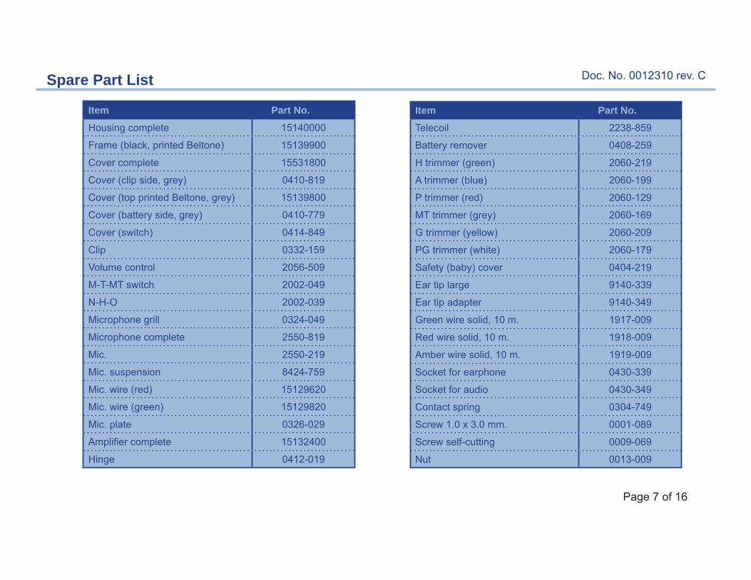
Spare Part List
Item Part No.Housing complete 15140000
Frame (black, printed Beltone) 15139900
Cover complete 15531800
Cover (clip side, grey) 0410-819
Cover (top printed Beltone, grey) 15139800
Cover (battery side, grey) 0410-779
Cover (switch) 0414-849
Clip 0332-159
Volume control 2056-509
M-T-MT switch 2002-049
N-H-O 2002-039
Microphone grill 0324-049
Microphone complete 2550-819
Mic. 2550-219
Mic. suspension 8424-759
Mic. wire (red) 15129620
Mic. wire (green) 15129820
Mic. plate 0326-029
Amplifi er complete 15132400
Hinge 0412-019
Item Part No.Telecoil 2238-859
Battery remover 0408-259
H trimmer (green) 2060-219
A trimmer (blue) 2060-199
P trimmer (red) 2060-129
MT trimmer (grey) 2060-169
G trimmer (yellow) 2060-209
PG trimmer (white) 2060-179
Safety (baby) cover 0404-219
Ear tip large 9140-339
Ear tip adapter 9140-349
Green wire solid, 10 m. 1917-009
Red wire solid, 10 m. 1918-009
Amber wire solid, 10 m. 1919-009
Socket for earphone 0430-339
Socket for audio 0430-349
Contact spring 0304-749
Screw 1.0 x 3.0 mm. 0001-089
Screw self-cutting 0009-069
Nut 0013-009

Doc. No. 0012310 rev. C
Page 8 of 16
Spare Part List
Item Part No.Volume control solder plate 0150-139
Blind plug 0414-569
BW ear tip LD-01 M 9140-319
BW ear tip LD-01 S 9140-329
Concerto II 3-prong cord (70cm/30 in) 7480-849
Alternative p/n:Concerto II 3-prong cord (50 cm/20 in) 7480-829
Bone conducter 100 OHM 9150-109
Headband 9150-211
Y-cord, 52 cm. 7001-149
Y-cord, 61 cm. 7001-159
Y-cord, 76 cm. 7001-169
V-cord, 50 cm. 7481-429
V-cord, 75 cm. 7481-449
Earphone SM-N CT 4115-019
Earphone SM-W CT 4125-019
Doc. No. 0012310 rev. C
Page 9 of 16
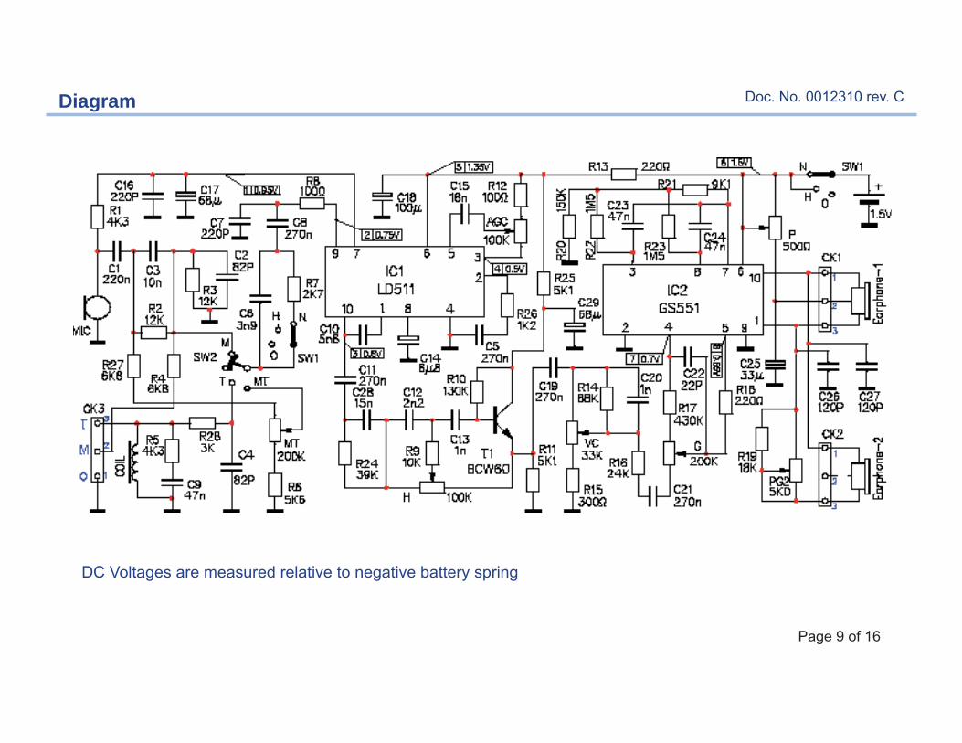
DC Voltages are measured relative to negative battery spring
Diagram

Doc. No. 0012310 rev. C
Page 10 of 16
To remove the cover from the backside of the instrument,use a small screwdriver for the 2 screws
Removal of the cover
Doc. No. 0012310 rev. C
Page 11 of 16
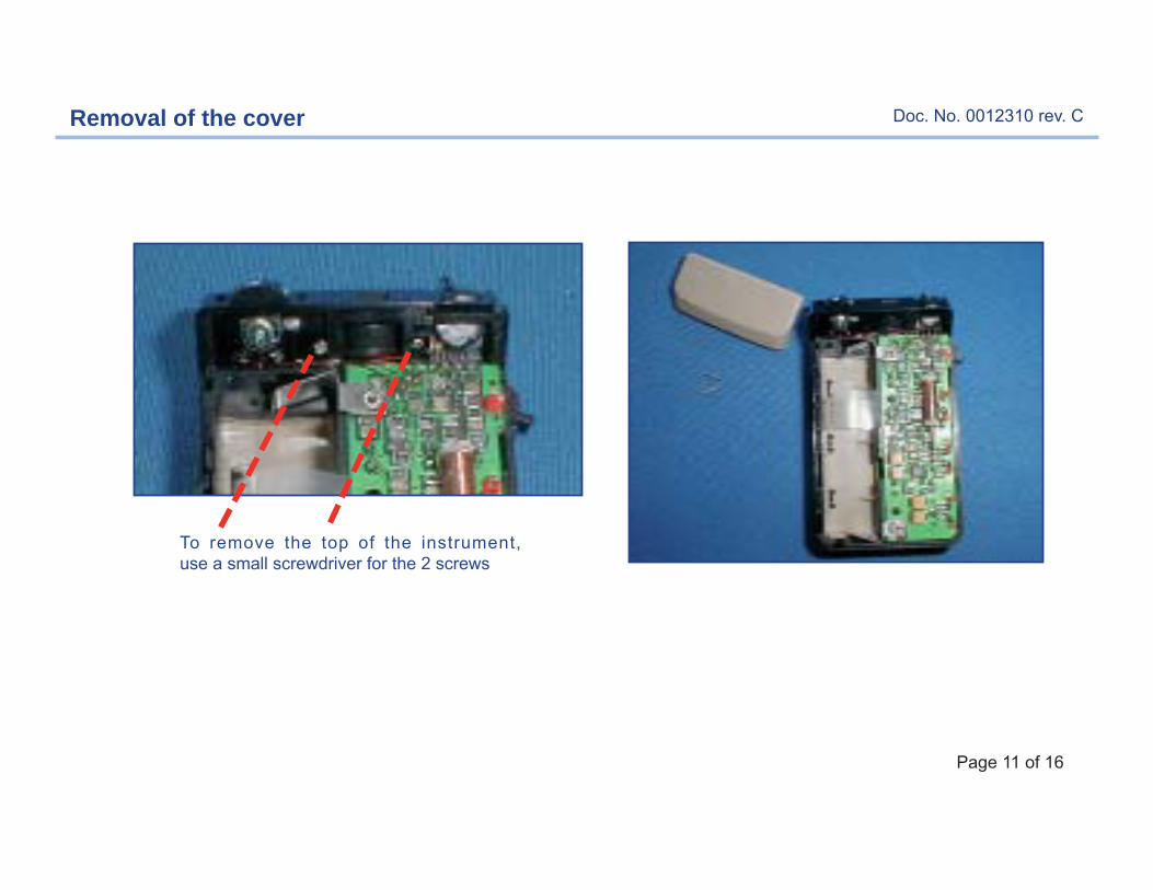
To remove the top of the instrument, use a small screwdriver for the 2 screws
Removal of the cover

Doc. No. 0012310 rev. C
Page 12 of 16
Remove the wires from the amplifi er.
M-T-MT switch
Volume controlFor wire connections see Amplifi er completedrawing
Mic(-)
Mic(+)
VC wires:Red 27mmYellow 20mmGreen 21mm
Wires of the amplifi er

Doc. No. 0012310 rev. C
Page 13 of 16
Red wire
Green wire
Mic.
Suspension Mic.
Mic. Plate
Rubber glue
Mic wiresGreen wire, 20mm P/N 15129820Red wire, 20mm P/N 15129620
Push up the Mic. from the outside
Remove the grill
Microphone complete
Removal of the microphone

Doc. No. 0012310 rev. C
Page 14 of 16
Remove the screw holding the amplifi er
Removal of the amplifi er
Doc. No. 0012310 rev. C
Page 15 of 16
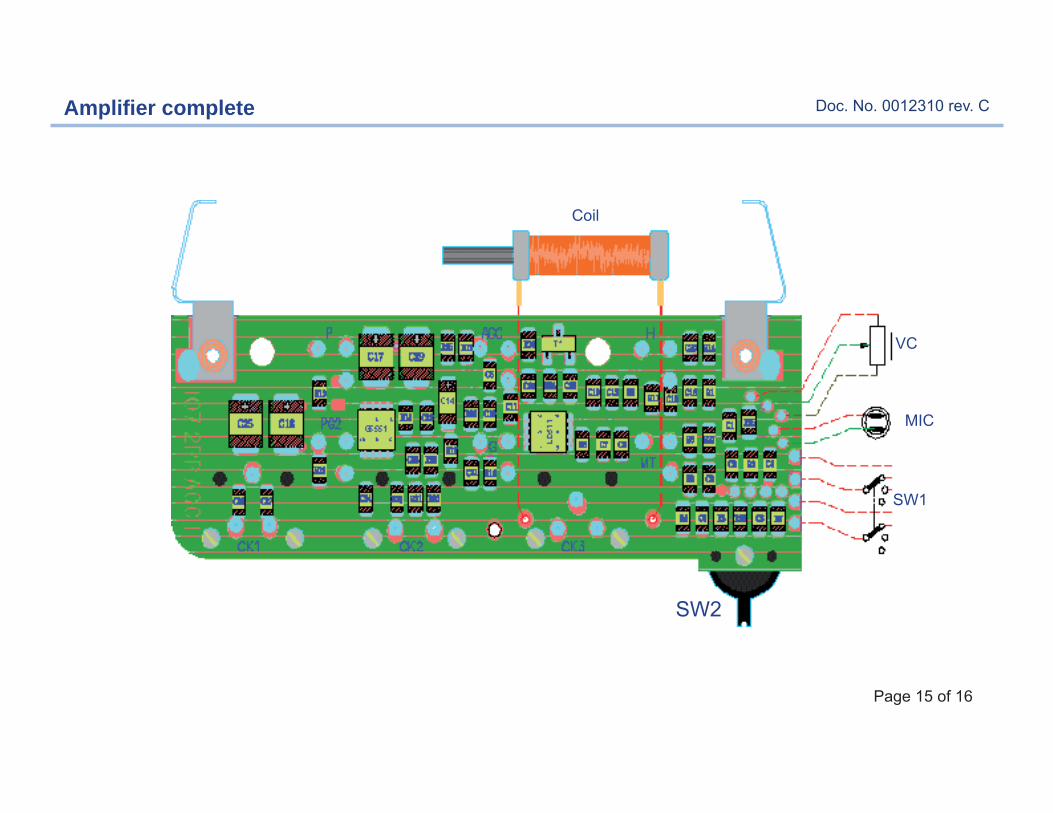
Screws (long) p/n 0009-139
Screw (short) p/n 0001-119
SW2
Coil
SW1
VC
MIC
Amplifi er complete

Doc. No. 0012310 rev. C
Page 16 of 16
Instrument complete