Technical Manual 0980 ESL 700 - Lumberg Automation USA · have the same level of knowledge as after...
33
Technical Manual LioN-M PROFINET 0980 ESL 700 0980 ESL 701
Transcript of Technical Manual 0980 ESL 700 - Lumberg Automation USA · have the same level of knowledge as after...

Technical Manual LioN-M PROFINET 0980 ESL 700 0980 ESL 701
Technical Manual LioN-M PROFINET
Subject to change without notice! Edition 1.0 / June 2012 Page 2 of 33
Table of contents
1. About this manual.......................................................................................................................... 4
1.1. Explanation of the symbolism .............................................................................................. 4
1.1.1. Use of notes.................................................................................................................... 4 1.1.2. Use of hazard warnings................................................................................................. 4
1.2. Safety guidelines.................................................................................................................... 5
1.2.1. Intended use................................................................................................................... 5
1.3. Qualified personnel................................................................................................................ 6
1.4. Version information about this manual ................................................................................ 6
2. System description........................................................................................................................ 7
3. Product overview........................................................................................................................... 8
3.1. Module variants...................................................................................................................... 8
3.2. Accessories ............................................................................................................................ 8
4. Mounting ........................................................................................................................................ 9
4.1. Outer dimensions................................................................................................................... 9
4.1.1. 0980 ESL 700 ................................................................................................................. 9 4.1.2. 0980 ESL 701 ............................................................................................................... 10
4.2. Notes for the field installation ..............................................................................................11
5. Wiring............................................................................................................................................ 12
5.1. Pin assignments................................................................................................................... 12
5.1.1. PROFINET ports, M12 (MICRO) female connectors, 4-pole, D-coded .................. 12 5.1.2. Power supply connectors, 7/8 inch (MINI), 5-pole, male/female connectors........ 12 5.1.3. Connections for sensors / actuators, M12 female connectors, 5-pole...................13
6. Configuration and commissioning ............................................................................................. 14
6.1. GSDML-file ........................................................................................................................... 14
6.2. MAC addresses.................................................................................................................... 14
6.3. SNMP .................................................................................................................................... 14
6.4. Configuration of the LioN-M PROFINET IO modules in STEP 7......................................15
6.4.1. Assignment of a definite device name in STEP 7 ..................................................... 16 6.4.2. Assignment of the device name to a LioN-M module.............................................. 16 6.4.3. Device replacement without removable media/PG ...................................................17 6.4.4. The parameter settings of the LioN-M modules ....................................................... 18 6.4.5. Prioritized startup ......................................................................................................... 19 6.4.6. Resetting the LioN-M modules to factory settings................................................... 19
7. Allocation of the process data ................................................................................................... 20
Technical Manual LioN-M PROFINET
Subject to change without notice! Edition 1.0 / June 2012 Page 3 of 33
7.1. Input data.............................................................................................................................. 20
7.2. Output data .......................................................................................................................... 20
8. Diagnostic properties of the modules ....................................................................................... 21
8.1. Optical diagnostic indicators .............................................................................................. 21
8.2. Diagnostic display in the integrated web server............................................................... 21
8.3. Alarm messages and error messages of the LioN-M modules on PROFINET.............. 22
8.3.1. Evaluation of alarms in STEP 7................................................................................... 22 8.3.2. Structure of the diagnostic data records................................................................... 22
9. The embedded web server......................................................................................................... 24
9.1. The home page (Home)....................................................................................................... 24
9.2. The configuration page (Config)......................................................................................... 25
9.3. The status page (Status) ..................................................................................................... 26
9.4. The page with contact information (Contact).................................................................... 27
9.5. Reading the process and diagnostic data using the embedded web server ................ 28
10. Firmware update of both LioN-M I/O-modules ........................................................................ 29
11. Technical Data ..............................................................................................................................31
11.1. General data ..........................................................................................................................31
11.2. Technical data of the bus system .......................................................................................31
11.3. Technical data of the power supply for the electronics and sensors..............................31
11.4. Technical data of the power supply for the actuators ..................................................... 32
11.5. Technical data of the input circuits.................................................................................... 32
11.6. Technical data of the output circuits ..................................................................................33
11.7. LED indicators.......................................................................................................................33
Technical Manual LioN-M PROFINET
Subject to change without notice! Edition 1.0 / June 2012 Page 4 of 33
1. About this manual Please, read the assembly and operating instructions of this manual carefully, before you put the LioN-M I/O-modules with PROFINET interface into operation. The manual should be kept at a place that is accessible to all users. The texts, illustrations, diagrams and examples being used in this manual are solely intended to explain the operation and application of the LioN-M I/O-modules 0980 ESL 700 and 0980 ESL 701with PROFINET interface. To obtain further information on the installation and putting into operation of the devices, please do not hesitate to contact us. We will be glad to be at your disposal at any time. Belden Deutschland GmbH – Lumberg Automation™– Im Gewerbepark 2 D-58579 Schalksmuehle Germany Phone: +49 (0) 23 55 / 5044-000 Fax: +49 (0) 23 55 / 5044-333 Email: [email protected] Internet: www.lumberg-automation.com Belden Deutschland GmbH -Lumberg Automation™- reserves the right of any technical changes or changes to this manual without prior notice. 1.1. Explanation of the symbolism 1.1.1. Use of notes References to important information are marked particularly. They are displayed as follows.
1.1.2. Use of hazard warnings Hazard warnings are marked as follows:
DANGER: Failure to observe appropriate precautions may cause danger to the life and health of the user.
ATTENTION: The non-observance of appropriate precautions may cause damage to other equipment or material assets.

Technical Manual LioN-M PROFINET
Subject to change without notice! Edition 1.0 / June 2012 Page 5 of 33
1.2. Safety guidelines 1.2.1. Intended use The devices described in this manual are intended to be used as decentralized input / output modules in a PROFINET IO network. Our products are designed, manufactured, tested and documented with respect to common safety standards. With attention to the handling specifications for planning, development and mounting as well as the safety instructions our products do not cause any danger to persons and property under normal conditions. The modules comply to the rules of the
EMC Directive (89/336/EEC, 93/68/EEC and 93/44/EEC) Low Voltage Directive (73/23/EEC)
They are designed to be used in the industrial sector. The industrial environment is characterized by the fact that electrical consumers are not connected directly to the public low voltage network. For the application in residential areas, business areas and commercial areas additional measures are to be taken.
Caution! This equipment can cause interferences in the residential area. In this case the operator can be asked to accomplish appropriate measures.
The proper and safe function of the product requires an appropriate transport, storage, installation and mounting as well as a careful operation. The intended operation of the device is only guaranteed with a completely installed housing. All devices connected to this equipment must fulfil the requirements of the EN 61558-2-4 and EN 61558-2-6. Projecting, installation, commissioning, maintenance and test of the devices may be carried out only by an approved qualified electrical specialist who is familiar with the security standards of the automation technology. During projecting, installation, commissioning, maintenance and test of the devices the safety regulations and accident prevention instructions in the specific application case have to be considered. Only cables and accessories shall be installed that correspond to the requirements and regulations for safety, electromagnetic compatibility and, if necessary, telecommunication terminals as well as the specification data. More information about the cables and accessories that are admitted for installation may be obtained from Belden Deutschland GmbH – Lumberg Automation™- or are described in this technical manual.

Technical Manual LioN-M PROFINET
Subject to change without notice! Edition 1.0 / June 2012 Page 6 of 33
1.3. Qualified personnel The requirements for the personnel depend on the requirement profile described by the ZVEI and VDMA or comparable organizations. Only electrical specialists, who know the content of this manual, may install and maintain the described products. These are persons who
can assess the works to be performed and recognize possible dangers based on their technical education, knowledge and experience as well as their knowledge of the relevant standards.
have the same level of knowledge as after a technical education due to an activity in a comparable area for several years.
Modifications to the hard- and software of our products, as far as they are not described in this technical manual, may be carried out only by Belden Deutschland GmbH -Lumberg Automation™.
ATTENTION! Unqualified modifications to the hardware or software or the non-observance of the warning instructions given in this technical manual can entail heavy personal damages or damages to property.
1.4. Version information about this manual
Index Created Changed Changed Changed Changed Changed Version number Draft 0.9 1.0
Date January 2012 February 2012
June 2012
Name/Department Knipp/PA Knipp/PA Knipp/PA
Technical Manual LioN-M PROFINET
Subject to change without notice! Edition 1.0 / June 2012 Page 7 of 33
2. System description The LioN (Lumberg-I/O-Network)-M module series contains I/O modules for the decentralized operation in rough industrial environment. They offer an easy handling of the I/O data in a higher-level bus system. They are suited particularly for application places in machines and assemblies with distributed I/O concentrations over larger distances. By the compact dimensions and the low weight the modules can be used under limited space conditions and on handling devices. As a protection class LioN-M I/O-modules offer IP 67. For the connection with a higher-level fieldbus system different interfaces are available. Current and widespread fieldbus systems are supported. This manual describes two LioN-M modules with PROFINET IO interface. The integrated switch allows the connection of the modules to each other in a line topology as usual in the fieldbus technology. The LioN-M I/O-module 0980 ESL 700 works as a slave device in a PROFINET IO network. It offers 16 digital I/O-channels with universal I/O-functionality. Each of the 16 channels can be used as a digital input or output independently from another channel. The input or output functionality is determined during the PLC programming. There is no additional configuration necessary. In applications which require digital inputs only the I/O-module 0980 ESL 701 can be used. This module also has a PROFINET IO interface and offers 16 digital input channels.

Technical Manual LioN-M PROFINET
Subject to change without notice! Edition 1.0 / June 2012 Page 8 of 33
3. Product overview 3.1. Module variants
Part number Description I/O connection Design LioN-M universal I/O 0980 ESL 700 Decentralized I/O module with 16
universally usable channels as digital inputs or outputs. Connection of the peripherals by 8 M12 sockets.
8 M12 sockets M
LioN-M digital input 0980 ESL 701 Decentralized I/O module with 16 digital
inputs. Connection of the peripherals by 8 M12 sockets.
8 M12 sockets M
3.2. Accessories
Part number Beschreibung PROFINET 0985 342 100/… M Connecting cable for PROFINET, assembled on both sides with M12
connector, straight, 4-pole, D-coded 0985 342 102/… M Connecting cable for PROFINET, assembled on one side with M12
connector, straight, 4-pole, D-coded 0985 342 104/… M Connecting cable for PROFINET, assembled on both sides with M12
connector, straight, 4-pole, D-coded and RJ45 connector, straight Power supply 0905 204 301/… M Connecting cable for power supply, assembled on one side with 7/8“
female connector, straight, 5-pole 0905 204 302/… M Connecting cable for power supply, assembled on both sides with
7/8“ connectors male/female, straight, 5-pole. 0905 204 303/… M Connecting cable for power supply, assembled on one side with 7/8“
male connector, straight, 5-pole 0905 204 308/… M Connecting cable for power supply, assembled on one side with 7/8“
female connector, angled, 5-pole 0905 204 309/… M Connecting cable for power supply, assembled on both sides with
7/8“ connectors male/female, angled, 5-pole 0905 204 310/… M Connecting cable for power supply, assembled on one side with 7/8“
male connector, angled, 5-pole Field attachable connectors 0986 EMC 102 Field attachable M12-connector for PROFINET cable, straight, 4-pole,
D-coded, with spring type terminals RSC 50/11 Field attachable 7/8“-connector for power supply, male, straight, 5-
pole, for cable diameter 8.0 -10.0 mm RKC 50/11 Field attachable 7/8“-connector for power supply, female, straight,
5-pole, for cable diameter 8.0 -10.0 mm Other accessories M12 protective cap ZVK Designation labels ZBR 9/40

Technical Manual LioN-M PROFINET
Subject to change without notice! Edition 1.0 / June 2012 Page 9 of 33
4. Mounting 4.1. Outer dimensions 4.1.1. 0980 ESL 700

Technical Manual LioN-M PROFINET
Subject to change without notice! Edition 1.0 / June 2012 Page 10 of 33
4.1.2. 0980 ESL 701
Technical Manual LioN-M PROFINET
Subject to change without notice! Edition 1.0 / June 2012 Page 11 of 33
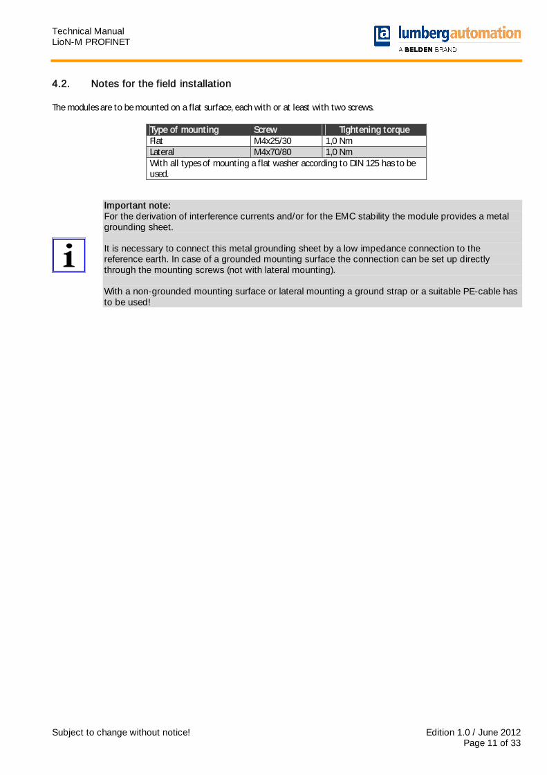
4.2. Notes for the field installation The modules are to be mounted on a flat surface, each with or at least with two screws.
Type of mounting Screw Tightening torque Flat M4x25/30 1,0 Nm Lateral M4x70/80 1,0 Nm With all types of mounting a flat washer according to DIN 125 has to be used.
Important note: For the derivation of interference currents and/or for the EMC stability the module provides a metal grounding sheet. It is necessary to connect this metal grounding sheet by a low impedance connection to the reference earth. In case of a grounded mounting surface the connection can be set up directly through the mounting screws (not with lateral mounting). With a non-grounded mounting surface or lateral mounting a ground strap or a suitable PE-cable has to be used!
Technical Manual LioN-M PROFINET
Subject to change without notice! Edition 1.0 / June 2012 Page 12 of 33
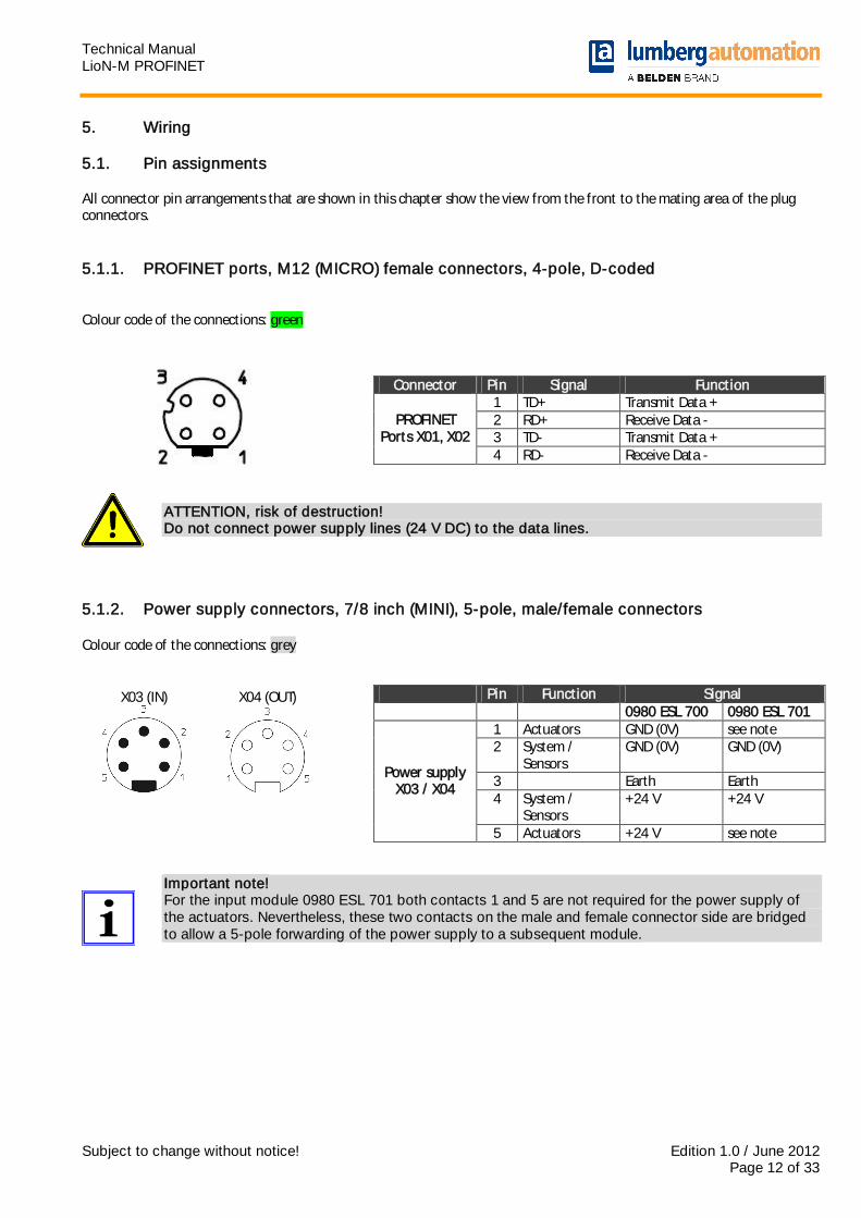
5. Wiring 5.1. Pin assignments All connector pin arrangements that are shown in this chapter show the view from the front to the mating area of the plug connectors. 5.1.1. PROFINET ports, M12 (MICRO) female connectors, 4-pole, D-coded Colour code of the connections: green
ATTENTION, risk of destruction! Do not connect power supply lines (24 V DC) to the data lines.
5.1.2. Power supply connectors, 7/8 inch (MINI), 5-pole, male/female connectors Colour code of the connections: grey X03 (IN) X04 (OUT)
Important note! For the input module 0980 ESL 701 both contacts 1 and 5 are not required for the power supply of the actuators. Nevertheless, these two contacts on the male and female connector side are bridged to allow a 5-pole forwarding of the power supply to a subsequent module.
Connector Pin Signal Function 1 TD+ Transmit Data + 2 RD+ Receive Data - 3 TD- Transmit Data +
PROFINET Ports X01, X02
4 RD- Receive Data -
Pin Function Signal 0980 ESL 700 0980 ESL 701
1 Actuators GND (0V) see note 2 System /
Sensors GND (0V) GND (0V)
3 Earth Earth 4 System /
Sensors +24 V +24 V
Power supply X03 / X04
5 Actuators +24 V see note
Technical Manual LioN-M PROFINET
Subject to change without notice! Edition 1.0 / June 2012 Page 13 of 33
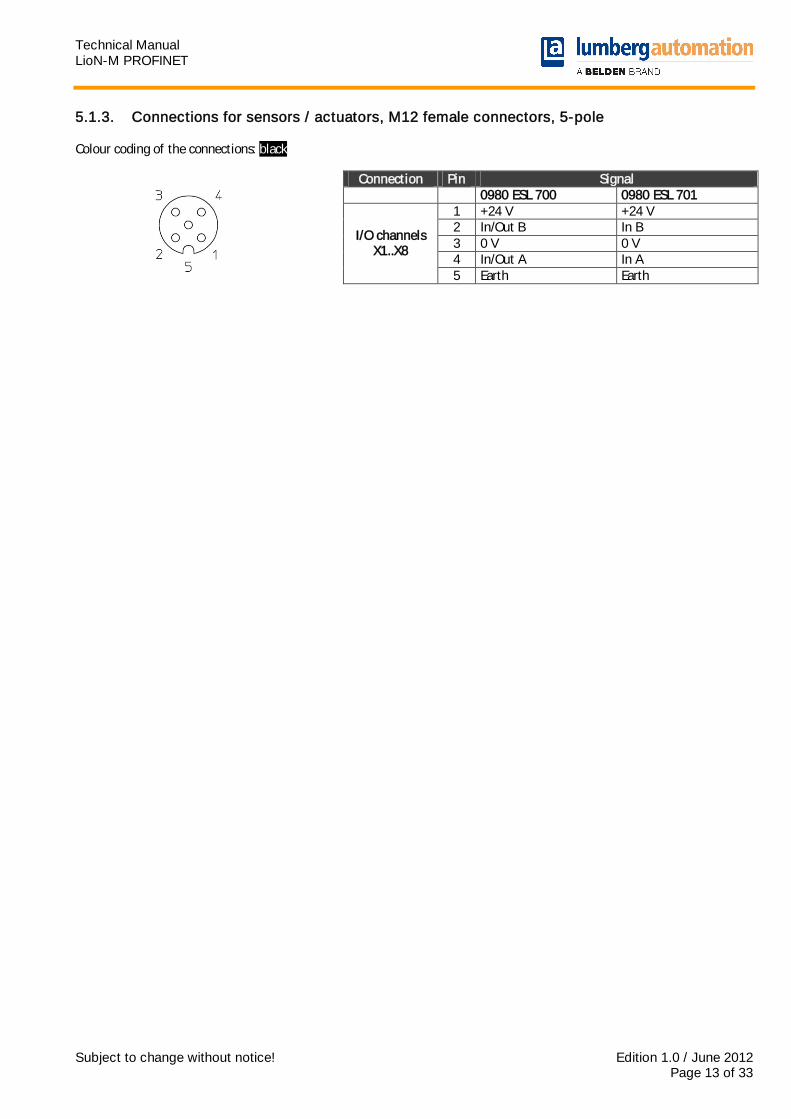
5.1.3. Connections for sensors / actuators, M12 female connectors, 5-pole Colour coding of the connections: black
Connection Pin Signal 0980 ESL 700 0980 ESL 701
1 +24 V +24 V 2 In/Out B In B 3 0 V 0 V 4 In/Out A In A
I/O channels X1..X8
5 Earth Earth

Technical Manual LioN-M PROFINET
Subject to change without notice! Edition 1.0 / June 2012 Page 14 of 33
6. Configuration and commissioning The configuration and commissioning of the LioN-M PROFINET IO modules described on the following pages was accomplished with the help of the STEP 7 software from the Siemens AG. In case of using a control system from another controller supplier please attend to the associated documentation. 6.1. GSDML-file For the configuration of the LioN-M modules in the control system a GSD-file in the XML format is required. The file can be downloaded from our homepage
http://www.beldensolutions.com/en/Service/Downloadcenter/Software_Lumberg/index.phtml On request the GSDML file would be sent also by the support team. The name of the file is as follows:
GSDML-V2.25-LumbergAutomation-LioN M-0980ESL70x-yyyymmdd, in which „yyyymmdd“ expresses the release date of the file. In STEP 7 you create a new project and open the hardware manager HW-Config. By the menu command Options – Install GSD File… and the following dialog the GSD file is installed. Afterwards the LioN-M I/O modules with PROFINET interface are available in the hardware catalogue. 6.2. MAC addresses The modules get three MAC addresses assigned on delivery. These are unique and cannot be changed by the user. 6.3. SNMP The modules support the Ethernet network protocol SNMP (Simple Network Management Protocol). The information of the network management is presented according to the MIB-II (Management Information Base) which is defined in the RFC 1213.
Technical Manual LioN-M PROFINET
Subject to change without notice! Edition 1.0 / June 2012 Page 15 of 33
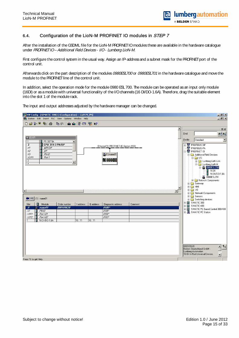
6.4. Configuration of the LioN-M PROFINET IO modules in STEP 7 After the installation of the GSDML file for the LioN-M PROFINET IO modules these are available in the hardware catalogue under PROFINET IO – Additional Field Devices - I/O - Lumberg LioN-M. First configure the control system in the usual way. Assign an IP-address and a subnet mask for the PROFINET port of the control unit. Afterwards click on the part description of the modules 0980ESL700 or 0980ESL701 in the hardware catalogue and move the module to the PROFINET line of the control unit. In addition, select the operation mode for the module 0980 ESL 700. The module can be operated as an input only module (16DI) or as a module with universal functionality of the I/O channels (16 DI/DO-1.6A). Therefore, drag the suitable element into the slot 1 of the module rack. The input and output addresses adjusted by the hardware manager can be changed.
Technical Manual LioN-M PROFINET
Subject to change without notice! Edition 1.0 / June 2012 Page 16 of 33
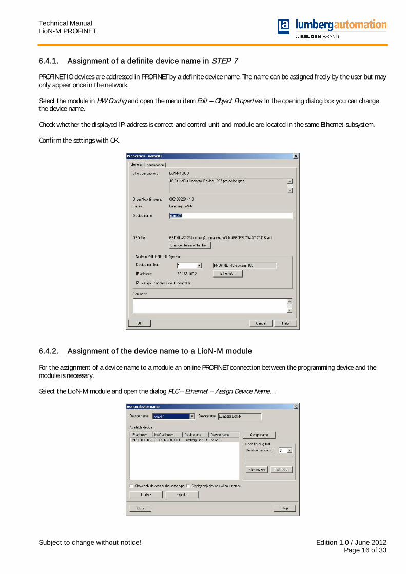
6.4.1. Assignment of a definite device name in STEP 7 PROFINET IO devices are addressed in PROFINET by a definite device name. The name can be assigned freely by the user but may only appear once in the network. Select the module in HW Config and open the menu item Edit – Object Properties. In the opening dialog box you can change the device name. Check whether the displayed IP-address is correct and control unit and module are located in the same Ethernet subsystem. Confirm the settings with OK.
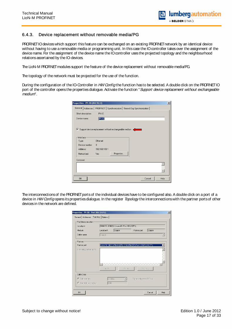
6.4.2. Assignment of the device name to a LioN-M module For the assignment of a device name to a module an online PROFINET connection between the programming device and the module is necessary. Select the LioN-M module and open the dialog PLC – Ethernet – Assign Device Name…
Technical Manual LioN-M PROFINET
Subject to change without notice! Edition 1.0 / June 2012 Page 17 of 33
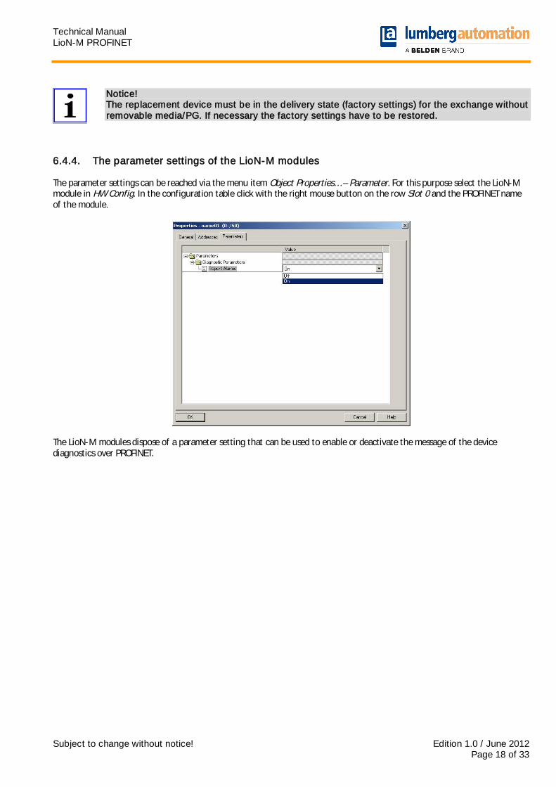
6.4.3. Device replacement without removable media/PG PROFINET IO devices which support this feature can be exchanged on an existing PROFINET network by an identical device without having to use a removable media or programming unit. In this case the IO controller takes over the assignment of the device name. For the assignment of the device name the IO controller uses the projected topology and the neighbourhood relations ascertained by the IO-devices. The LioN-M PROFINET modules support the feature of the device replacement without removable media/PG. The topology of the network must be projected for the use of the function. During the configuration of the IO-Controller in HW Config the function has to be selected. A double click on the PROFINET IO port of the controller opens the properties dialogue. Activate the function “Support device replacement without exchangeable medium”.
The interconnections of the PROFINET ports of the individual devices have to be configured also. A double click on a port of a device in HW Config opens its properties dialogue. In the register Topology the interconnections with the partner ports of other devices in the network are defined.
Technical Manual LioN-M PROFINET
Subject to change without notice! Edition 1.0 / June 2012 Page 18 of 33
Notice! The replacement device must be in the delivery state (factory settings) for the exchange without removable media/PG. If necessary the factory settings have to be restored.
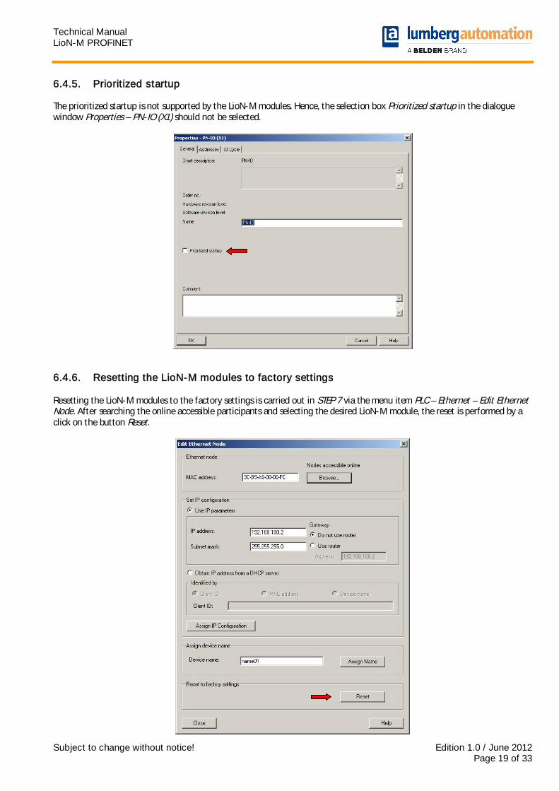
6.4.4. The parameter settings of the LioN-M modules The parameter settings can be reached via the menu item Object Properties… – Parameter. For this purpose select the LioN-M module in HW Config. In the configuration table click with the right mouse button on the row Slot 0 and the PROFINET name of the module.
The LioN-M modules dispose of a parameter setting that can be used to enable or deactivate the message of the device diagnostics over PROFINET.
Technical Manual LioN-M PROFINET
Subject to change without notice! Edition 1.0 / June 2012 Page 19 of 33
6.4.5. Prioritized startup The prioritized startup is not supported by the LioN-M modules. Hence, the selection box Prioritized startup in the dialogue window Properties – PN-IO (X1) should not be selected.
6.4.6. Resetting the LioN-M modules to factory settings Resetting the LioN-M modules to the factory settings is carried out in STEP 7 via the menu item PLC – Ethernet – Edit Ethernet Node. After searching the online accessible participants and selecting the desired LioN-M module, the reset is performed by a click on the button Reset.
Technical Manual LioN-M PROFINET
Subject to change without notice! Edition 1.0 / June 2012 Page 20 of 33
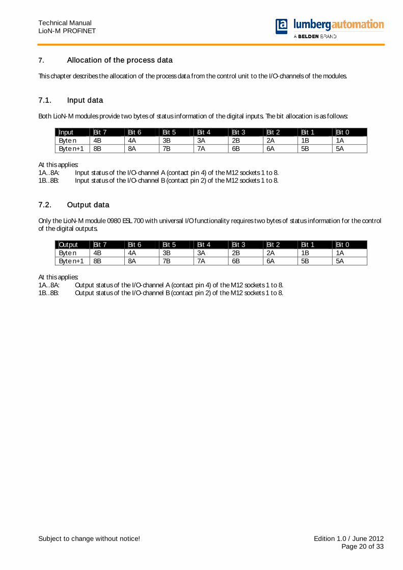
7. Allocation of the process data This chapter describes the allocation of the process data from the control unit to the I/O-channels of the modules. 7.1. Input data Both LioN-M modules provide two bytes of status information of the digital inputs. The bit allocation is as follows:
Input Bit 7 Bit 6 Bit 5 Bit 4 Bit 3 Bit 2 Bit 1 Bit 0 Byte n 4B 4A 3B 3A 2B 2A 1B 1A Byte n+1 8B 8A 7B 7A 6B 6A 5B 5A
At this applies: 1A…8A: Input status of the I/O-channel A (contact pin 4) of the M12 sockets 1 to 8. 1B…8B: Input status of the I/O-channel B (contact pin 2) of the M12 sockets 1 to 8. 7.2. Output data Only the LioN-M module 0980 ESL 700 with universal I/O functionality requires two bytes of status information for the control of the digital outputs.
Output Bit 7 Bit 6 Bit 5 Bit 4 Bit 3 Bit 2 Bit 1 Bit 0 Byte n 4B 4A 3B 3A 2B 2A 1B 1A Byte n+1 8B 8A 7B 7A 6B 6A 5B 5A
At this applies: 1A…8A: Output status of the I/O-channel A (contact pin 4) of the M12 sockets 1 to 8. 1B…8B: Output status of the I/O-channel B (contact pin 2) of the M12 sockets 1 to 8.
Technical Manual LioN-M PROFINET
Subject to change without notice! Edition 1.0 / June 2012 Page 21 of 33
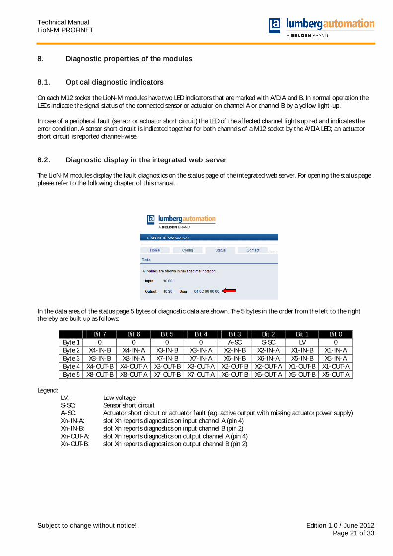
8. Diagnostic properties of the modules 8.1. Optical diagnostic indicators On each M12 socket the LioN-M modules have two LED indicators that are marked with A/DIA and B. In normal operation the LEDs indicate the signal status of the connected sensor or actuator on channel A or channel B by a yellow light-up. In case of a peripheral fault (sensor or actuator short circuit) the LED of the affected channel lights up red and indicates the error condition. A sensor short circuit is indicated together for both channels of a M12 socket by the A/DIA LED; an actuator short circuit is reported channel-wise. 8.2. Diagnostic display in the integrated web server The LioN-M modules display the fault diagnostics on the status page of the integrated web server. For opening the status page please refer to the following chapter of this manual.
In the data area of the status page 5 bytes of diagnostic data are shown. The 5 bytes in the order from the left to the right thereby are built up as follows:
Bit 7 Bit 6 Bit 5 Bit 4 Bit 3 Bit 2 Bit 1 Bit 0 Byte 1 0 0 0 0 A-SC S-SC LV 0 Byte 2 X4-IN-B X4-IN-A X3-IN-B X3-IN-A X2-IN-B X2-IN-A X1-IN-B X1-IN-A Byte 3 X8-IN-B X8-IN-A X7-IN-B X7-IN-A X6-IN-B X6-IN-A X5-IN-B X5-IN-A Byte 4 X4-OUT-B X4-OUT-A X3-OUT-B X3-OUT-A X2-OUT-B X2-OUT-A X1-OUT-B X1-OUT-A Byte 5 X8-OUT-B X8-OUT-A X7-OUT-B X7-OUT-A X6-OUT-B X6-OUT-A X5-OUT-B X5-OUT-A
Legend:
LV: Low voltage S-SC: Sensor short circuit A-SC: Actuator short circuit or actuator fault (e.g. active output with missing actuator power supply) Xn-IN-A: slot Xn reports diagnostics on input channel A (pin 4) Xn-IN-B: slot Xn reports diagnostics on input channel B (pin 2) Xn-OUT-A: slot Xn reports diagnostics on output channel A (pin 4) Xn-OUT-B: slot Xn reports diagnostics on output channel B (pin 2)

Technical Manual LioN-M PROFINET
Subject to change without notice! Edition 1.0 / June 2012 Page 22 of 33
8.3. Alarm messages and error messages of the LioN-M modules on PROFINET
Note: The transmission of the alarm and error messages on PROFINET is only performed if the parameter for the diagnostics is enabled during the configuration of the modules in the control unit.
If both LioN-M modules detect an error condition, they trigger an alarm message. The modules support diagnostic alarms. Diagnostic alarms are triggered by peripheral faults, as for example overload, short circuit, wire break. An alarm is triggered by a coming event (e. g. sensor short circuit), as well as by a going event. The evaluation of the alarms is carried out in dependence of the used PROFINET IO controller. 8.3.1. Evaluation of alarms in STEP 7 In STEP 7 the processing of the application program is interrupted by triggering a diagnostic alarm. A diagnostic organization block (fault OB) is called. The following organization blocks are used:
Cause of the alarm OB call Peripheral fault (short circuit, overload, broken wire, low voltage)
OB 82
Complete failure of a module OB 86 Based on the called OBs and their start information the first information about the cause of the fault and type of the fault is already delivered. More detailed information about the fault event can be obtained in the fault OB by calling the system function block SFB 54 RALRM (Read additional alarm information). The SFB 54 therefore has to be called in every fault OB. If the called fault OB is not available in the CPU, the CPU changes to the operation mode STOP. It is also possible to call a diagnostic data record by its data record number with the help of the system function block SFB 52 "RDREC" in OB 1. 8.3.2. Structure of the diagnostic data records For the presentation of the diagnostic data records, the block version 0x0101 and format identifier (USI, User Structure Identifier) 0x8000 are used. The data values ChannelNumber and ChannelErrorType contain the following values in dependence of the occurred error.
Error type Reference ChannelNumber ChannelErrorType Low voltage of the actuator power
Module 0x8000 0x0002
Sensor short circuit M12 slot 0x0001 to 0x0008 Number of the M12 slot
0x0102
Actuator short circuit
Channel A of a M12 slot 0x0001 to 0x0008 Number of the M12 slot
0x0100
Actuator short circuit
Channel B of a M12 slot 0x0001 to 0x0008 Number of the M12 slot
0x0101
With an accumulation of errors the section Channel diagnostics with the data values ChannelNumber, ChannelProperties and ChannelErrorType is repeated for every error in the diagnostic data record. The following pictures illustrate this relationship using the online diagnostics in STEP 7.

Technical Manual LioN-M PROFINET
Subject to change without notice! Edition 1.0 / June 2012 Page 23 of 33
To display the diagnostics in STEP 7 select the faulty I/O-module in the hardware manager by a mouse click and open the online diagnostics with the menu item PLC – Module Information – IO-Device Diagnostics.
Pressing the button Hex Format... in the above window provides the presentation of the diagnostic data record in the hexadecimal format and its structure.

Technical Manual LioN-M PROFINET
Subject to change without notice! Edition 1.0 / June 2012 Page 24 of 33
9. The embedded web server Both LioN-M modules have an embedded web server that provides functions for the configuration of the modules and the display of status and diagnostic information. With the help of a standard web browser it is possible to get access to the provided functions over an existing TCP/IP connection. For the use of the web server the modules need an own IP address. According to the PROFINET standard all PROFINET IO devices are delivered with IP address 0.0.0.0. Consequently, a free IP address deviating from the factory settings has to be assigned to the modules before using the web server. The assignment of the IP address can be carried out with STEP 7, for example, as described in chapter 6 of this manual. As far as the IO-controller self-assigns the IP-address, this IP-address can be used to call the web server. 9.1. The home page (Home) Enter http:// in the address bar of your web browser, followed by the IP address, for example http://192.168.100.2. If the home page of the modules does not open, check your browser and firewall settings.
Technical Manual LioN-M PROFINET
Subject to change without notice! Edition 1.0 / June 2012 Page 25 of 33
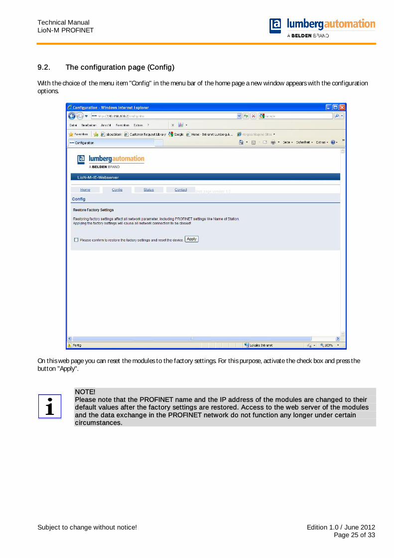
9.2. The configuration page (Config) With the choice of the menu item "Config" in the menu bar of the home page a new window appears with the configuration options.
On this web page you can reset the modules to the factory settings. For this purpose, activate the check box and press the button "Apply".
NOTE! Please note that the PROFINET name and the IP address of the modules are changed to their default values after the factory settings are restored. Access to the web server of the modules and the data exchange in the PROFINET network do not function any longer under certain circumstances.
Technical Manual LioN-M PROFINET
Subject to change without notice! Edition 1.0 / June 2012 Page 26 of 33
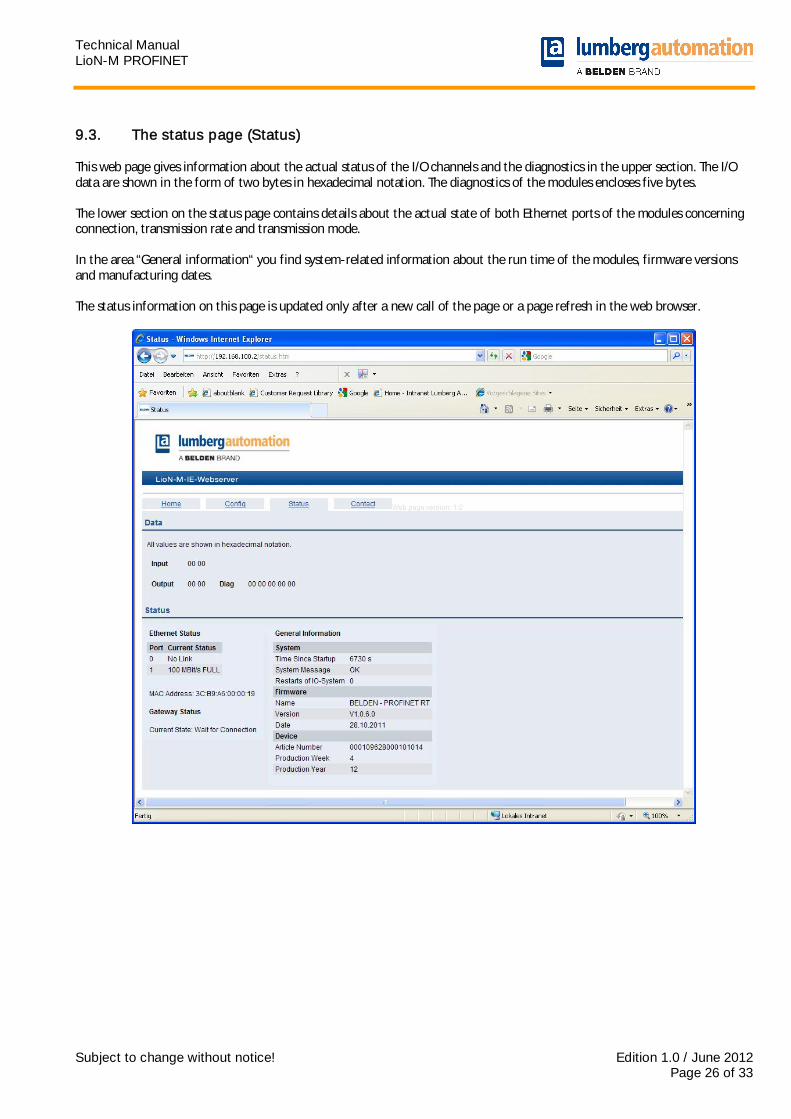
9.3. The status page (Status) This web page gives information about the actual status of the I/O channels and the diagnostics in the upper section. The I/O data are shown in the form of two bytes in hexadecimal notation. The diagnostics of the modules encloses five bytes. The lower section on the status page contains details about the actual state of both Ethernet ports of the modules concerning connection, transmission rate and transmission mode. In the area “General information“ you find system-related information about the run time of the modules, firmware versions and manufacturing dates. The status information on this page is updated only after a new call of the page or a page refresh in the web browser.
Technical Manual LioN-M PROFINET
Subject to change without notice! Edition 1.0 / June 2012 Page 27 of 33
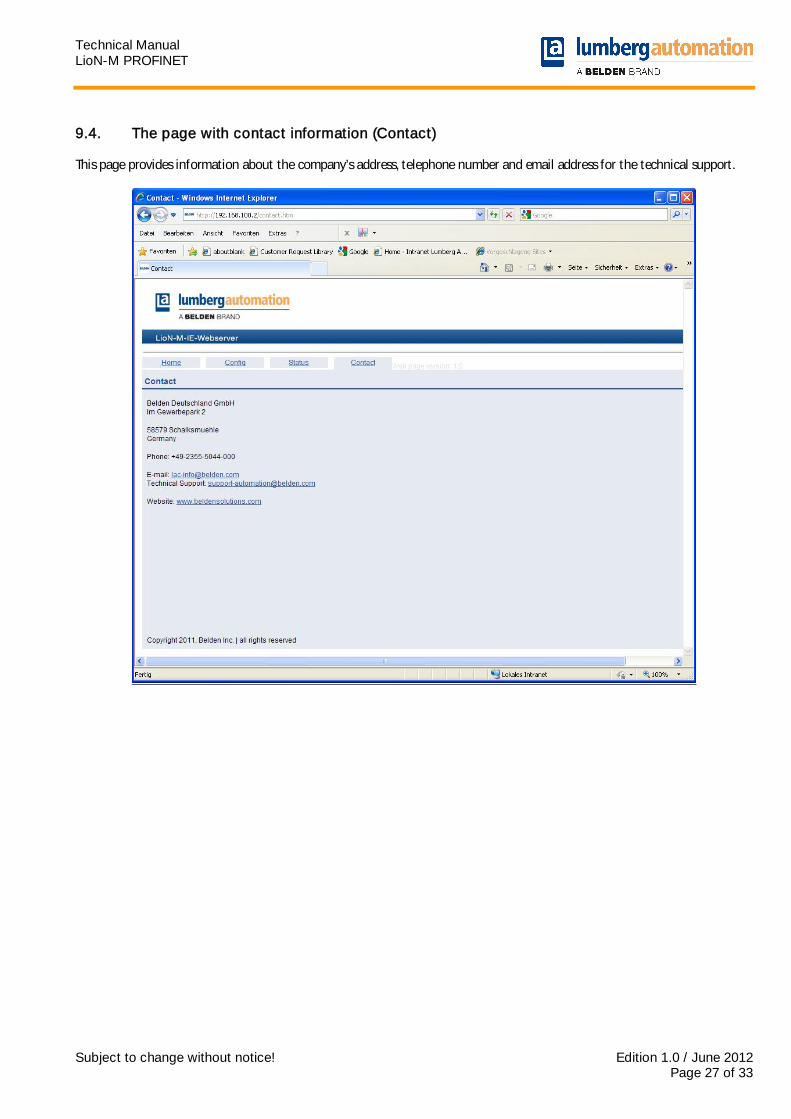
9.4. The page with contact information (Contact) This page provides information about the company’s address, telephone number and email address for the technical support.
Technical Manual LioN-M PROFINET
Subject to change without notice! Edition 1.0 / June 2012 Page 28 of 33
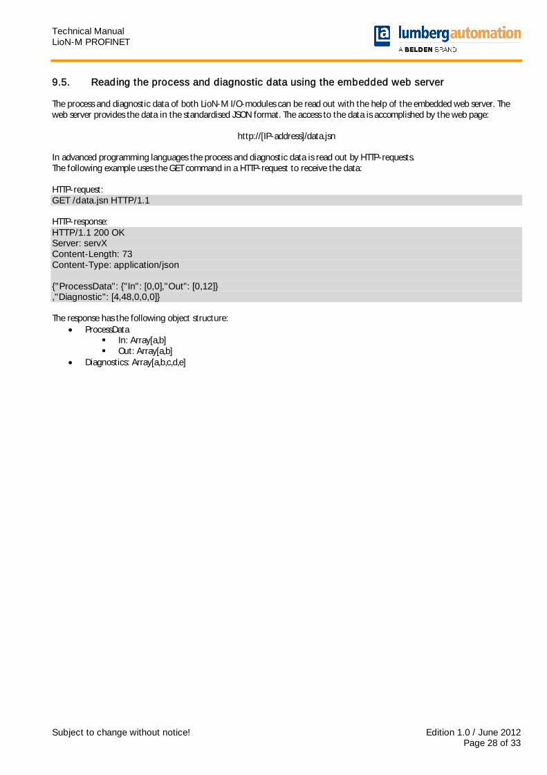
9.5. Reading the process and diagnostic data using the embedded web server The process and diagnostic data of both LioN-M I/O-modules can be read out with the help of the embedded web server. The web server provides the data in the standardised JSON format. The access to the data is accomplished by the web page:
http://[IP-address]/data.jsn
In advanced programming languages the process and diagnostic data is read out by HTTP-requests. The following example uses the GET command in a HTTP-request to receive the data: HTTP-request: GET /data.jsn HTTP/1.1 HTTP-response: HTTP/1.1 200 OK Server: servX Content-Length: 73 Content-Type: application/json {"ProcessData": {"In": [0,0],"Out": [0,12]} ,"Diagnostic": [4,48,0,0,0]} The response has the following object structure:
ProcessData In: Array[a,b] Out: Array[a,b]
Diagnostics: Array[a,b,c,d,e]

Technical Manual LioN-M PROFINET
Subject to change without notice! Edition 1.0 / June 2012 Page 29 of 33
10. Firmware update of both LioN-M I/O-modules The integrated web server of both LioN-M I/O-modules allows an update of the firmware of the modules. For the update of the firmware implemented web services are used. Before performing a firmware update the attention to the following instructions is highly recommended.
Important note! Please observe the following instructions for a firmware update of the modules very carefully, as otherwise the modules may no longer function properly. We recommend to perform the firmware update only if really needed. Please, use firmware files released exclusively by Belden Deutschland GmbH – Lumberg Automation™. We do not guarantee for non-compliance with these instructions.
1. Disconnect any connected sensors and actuators to the I/O-modules by unscrewing the M12 connectors.
2. Disconnect also the connection to your control unit and other PROFINET devices. Only the computer which is intended to carry out the update should be connected to the module.
3. Perform a power reset on the I/O-module by interrupting the power supply for a short time.
However, after starting the update it has to be ensured that the power supply cannot be interrupted any more. The green LED US must light permanently.
4. Make sure that a correct IP-address is assigned to the I/O-module. See chapter 6 for setting IP-parameters.
5. Start the web browser on your computer and open the homepage of the I/O-module to check the access to it.
6. Open the firmware transfer page of the I/O-module by entering http://[IP-address]/fwupdate in the address bar of
your web browser. It is not possible to access the firmware transfer page by other means. The following web page should open. This page identifies the version and date of the actual firmware and allows the selection and transfer of the new firmware file.
Technical Manual LioN-M PROFINET
Subject to change without notice! Edition 1.0 / June 2012 Page 30 of 33
7. Select the new firmware file by pressing the Search button and open the folder on your computer with the correct
file. The file shall be available in 8.3 notation with the file extension “.nxf”.
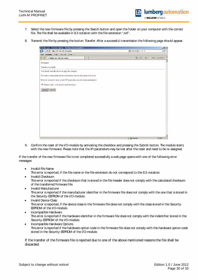
8. Transmit the file by pressing the button Transfer. After a successful transmission the following page should appear.
9. Confirm the reset of the I/O-module by activating the checkbox and pressing the Submit button. The module starts with the new firmware. Please note that the IP-parameters may be lost after the reset and need to be re-assigned.
If the transfer of the new firmware file is not completed successfully a web page opens with one of the following error messages:
Invalid File Name This error is reported, if the file name or the file extension do not correspond to the 8.3-notation.
Invalid Checksum This error is reported if the checksum that is stored in the file header does not comply with the calculated checksum of the transferred firmware file.
Invalid Manufacturer This error is reported if the manufacturer identifier in the firmware file does not comply with the one that is stored in the Security-EEPROM of the I/O-module.
Invalid Device Class This error is reported, if the device class in the firmware file does not comply with the class stored in the Security-EEPROM of the I/O-module.
Incompatible Hardware This error is reported if the hardware identifier in the firmware file does not comply with the indentifier stored in the Security-EEPROM of the I/O-module.
Incompatible Hardware Options This error is reported if the hardware option code in the firmware file does not comply with the hardware option code stored in the Security-EEPROM of the I/O-module.
If the transfer of the firmware file is rejected due to one of the above mentioned reasons the file shall be discarded.

Technical Manual LioN-M PROFINET
Subject to change without notice! Edition 1.0 / June 2012 Page 31 of 33
11. Technical Data 11.1. General data
Protection degree IP 67 (only in the screwed condition) Ambient temperature -10°C / +60°C Weight approx. 380 g Housing material PBT Vibration resistance 15 g / 5–500 Hz Shock resistance 50 g / 11 ms Torques:
Fastening screw M4 M12 connectors
1,0 Nm 0,5 Nm
11.2. Technical data of the bus system
Protocol PROFINET IO RT is supported
GSDML-file GSDML-V2.25-LumbergAutomation-LioN M-0980ESL70x-yyyymmdd.xml
Transmission rate 100 Mbit/s, Full Duplex Transmission method
Autonegotiation 100BASE-TX supported
Vendor code (VendorID) 0016AH Device code (DeviceID) 0303H Supported Ethernet protocols Ping
ARP LLDP SNMP (network diagnostics) DCP HTTP TCP/IP
Switch functionality integrated IRT is supported
PROFINET interface Connections Autocrossing
2 M12 sockets, 4-pole, D-coded (see pin assignments) is supported
11.3. Technical data of the power supply for the electronics and sensors
Rated voltage US 24 V DC Voltage range 19–30 V DC Current consumption electronics typ. 100 mA Voltage level sensors min. (USystem – 1,5 V) Current consumption sensors max. 200 mA at Tamb = 30 °C Reverse polarity protection yes Operation indicator LED green Connection 7/8"-male and female connectors, 5-pole;
see pin assignments
Technical Manual LioN-M PROFINET
Subject to change without notice! Edition 1.0 / June 2012 Page 32 of 33
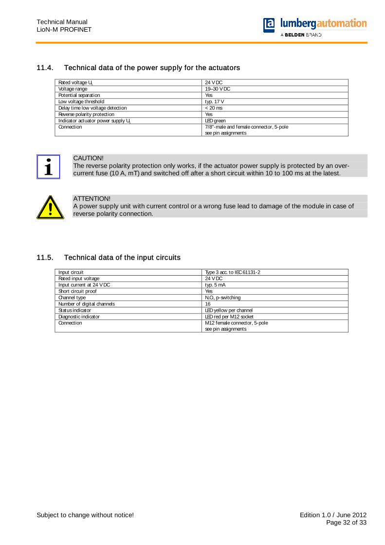
11.4. Technical data of the power supply for the actuators
Rated voltage UL 24 V DC Voltage range 19–30 V DC Potential separation Yes Low voltage threshold typ. 17 V Delay time low voltage detection < 20 ms Reverse polarity protection Yes Indicator actuator power supply UL LED green Connection 7/8"-male and female connector, 5-pole
see pin assignments
CAUTION! The reverse polarity protection only works, if the actuator power supply is protected by an over-current fuse (10 A, mT) and switched off after a short circuit within 10 to 100 ms at the latest.
ATTENTION! A power supply unit with current control or a wrong fuse lead to damage of the module in case of reverse polarity connection.
11.5. Technical data of the input circuits
Input circuit Type 3 acc. to IEC 61131-2 Rated input voltage 24 V DC Input current at 24 V DC typ. 5 mA Short circuit proof Yes Channel type N.O., p-switching Number of digital channels 16 Status indicator LED yellow per channel Diagnostic indicator LED red per M12 socket Connection M12 female connector, 5-pole
see pin assignments
Technical Manual LioN-M PROFINET
Subject to change without notice! Edition 1.0 / June 2012 Page 33 of 33
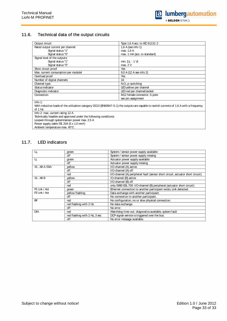
11.6. Technical data of the output circuits
Output circuit Type 1,6 A acc. to IEC 61131-2 Rated output current per channel: Signal status "1" Signal status "0"
1,6 A (see info 1) max. 1,9 A max. 1 mA (acc. to standard)
Signal level of the outputs: Signal status "1" Signal status "0"
min. (UL - 1 V) max. 2 V
Short circuit proof Yes Max. current consumption per modulel 9,0 A (12 A see info 2) Overload proof Yes Number of digital channels 16 Channel type N.O., p-switching Status indicator LED yellow per channel Diagnostic indicator LED red per channel/socket Connection M12 female connector, 5-pole
see pin assignment Info 1: With inductive loads of the utilization category DC13 (EN60947-5-1) the outputs are capable to switch currents of 1.6 A with a frequency of 1 Hz. Info 2: max. current rating 12 A Technically feasible and approved under the following conditions: Looped-through system/sensor power max. 2.5 A Power supply cable STL 204 (5 x 1.0 mm²) Ambient temperature max. 40°C
11.7. LED indicators
green System / sensor power supply available US off System / sensor power supply missing green Actuator power supply available UL off Actuator power supply missing yellow I/O-channel (A) active off I/O-channel (A) off
X1…X8 A /DIA
red I/O-channel (A) peripheral fault (sensor short circuit, actuator short circuit) yellow /O-channel (B) active off I/O-channel (B) off
X1…X8 B
red only 0980 ESL 700: I/O-channel (B) peripheral (actuator short circuit) green Ethernet connection to another participant exists. Link detected. yellow flashing Data exchange with another participant.
P1 Lnk / Act P2 Lnk / Act
off No connection to another participant. red No configuration, no or slow physical connection. red flashing with 2 Hz No data exchange.
BF
off No error. red Watchdog time-out; diagnostics available, system fault red flashing with 2 Hz, 3 sec DCP-signal-service is triggered over the bus.
DIA
off No error message available.


![Lumberg [Discover Agility] · 2018-10-16 · electrical engineering, automation and digitization solutions. It is this passion which made us establish the M12 circular connector as](https://static.fdocuments.in/doc/165x107/5fb5bc9338adaf51fd0fd6bb/lumberg-discover-agility-2018-10-16-electrical-engineering-automation-and-digitization.jpg)