TECHNICAL JOURNAL OF THE TELEVIS ON-RAD O … · Ideal for quick trips. 15T
70
OCTOBER, 1956 S THE TECHNICAL JOURNAL OF THE TELEVIS ON-RAD O TRADE adz'. ..4.4111110 TO SWITCH ON VIDEO SYNC SCUND BOARD MOTOR Automo'ic tuner -bar clrcurt of TV chassis -enote-control system. See circuit analysis fhls issue TO VOICE COIL B OUTPUT TRANS SELECTIVE TOP TDUCH CONSECUTIVE CHANNE_ ROCKER ARM CHANNEL SELECT ON -i 4 ® .-SELECTION r r 9-9-6 87S 4J3Hv7 NO1dI^(ryd 3 A431.1I:9V 3SitIl tr TO OUT> l TRANS DUMMY PLUG (PIN VIEW, www.americanradiohistory.com
Transcript of TECHNICAL JOURNAL OF THE TELEVIS ON-RAD O … · Ideal for quick trips. 15T

OCTOBER, 1956
S
THE TECHNICAL JOURNAL OF THE TELEVIS ON-RAD O TRADE
adz'. ..4.4111110 TO SWITCH ON
VIDEO SYNC SCUND BOARD
MOTOR
Automo'ic tuner -bar clrcurt of TV
chassis -enote-control system.
See circuit analysis fhls issue
TO VOICE COIL B OUTPUT TRANS
SELECTIVE TOP TDUCH CONSECUTIVE CHANNE_ ROCKER ARM CHANNEL SELECT ON -i 4 ® .-SELECTION
r r
9-9-6 87S 4J3Hv7
NO1dI^(ryd 3 A431.1I:9V
3SitIl tr
TO OUT> l TRANS
DUMMY PLUG (PIN VIEW,
www.americanradiohistory.com

only
CD:R, #R0-Dr2 have the
1. The Most Complete Line The CDR Rotor line is COMPLETE to every detail, with a model for every application! A distinct selling advantage because YOU can give your customer EXACTLY what is required! The RIGHT CDR Rotor for the RIGHT job.
111111r :7221111111
Completely AUTO- MATIC version of the TR -2 with all the powerful fea- tures that made it famous.
Completely AUTO- MATIC rotor, pow- er'ul and depend -
at le Modern de- sign cabinet. 4 wire cable.
1111111"':::2"="1111111
Completely AUTO- MATIC rotor with thrust bearing Handsome cabinet, 4 wire cable
CO RNELL-DUBILIER SOUTH PLAINFIELD. N. J.
TR -2
2 Pre -SOLD For You on TV to millions of viewers through an extensive coverage of audiences in every important TV market. Capture this pre -sold market by featuring these nationally advertised CDR ROTORS.
Heavy duty rotor with plastic cabinet, "compass control" illuminated perfect pattern dial, 8 wire cable.
/II
Heavyduty rotor, modern cabinet with METER con- trol dial, 4 wire cable
TR -12
Combination value complete rotor
with thrust bearing. Modern cabinet with meter control dial, uses 4 wire cable
THE RADIARTCpRP. CLEVELAND 13, OHIO
Ideal budget all- pyrpose rotor, new modern cabinet featuring peter control dial, wire :able.
1
www.americanradiohistory.com

"This new Crosley chassis
really saves us time and money!"
-reports H. HARMSON NEEL, Owner, Neel Television; President, TV Service Dealers Assoc., Phila.
'57 CROSLEY EASIEST -TO-SERVICE CHASSIS Doubles Servicemen's Efficiency- Cuts Call -Backs!
Another great TV advance from Crosley-the chassis designed with the serviceman in mind! "If all sets were made like Crosley, my service efficiency would double ... because Crosley sets can be serviced in half the time!" says Mr. Neel.
"The set's so easy to service that the job is done right the first time-no costly call-backs." Yes, you can build customer satisfaction and build your profits at the same time with Crosley. Many major repairs now can be done in the home. You can drastically reduce repair time- even in the shop! Look at the features described here and you'll see why Crosley is
KNOWN FOR THE NEWEST ... RESPECTED FOR THE BEST!
Test points are labeled and easily available from the rear without removing chassis. Quick circuit analysis and trouble -shooting make for simplified servicing.
95% of all parts replaced without removing chassis, without touch- ing a chassis bolt. Provision is even made for changing the power supply parts easily.
Has all the features Servicemen want- AND MORE!
Printed circuit board is translucent. Just place light behind it to trace circuitry.
Picture tube is removable from the front of set. Loosen four screws and tube slides out.
Even filter capacitors and selenium rectifiers can be replaced without removing chassis!
Transformers and chokes are screwed on-not riveted. Easy to service or replace!
Special Crosley funnel -guide helps find oscillator adjustment. Cuts down probing time!
Find tube blowouts with o screw- driver. Open heater tubes are a cinch to locate with the marked special test points. All receiving tubes easily replaced.
Picture tube comes out with the chassis. The tube mounting is a part of the chassis assembly for quick handling. Replacement and set-up are quicker and easier.
rosleyand benclix F-i O I E A P f= L- I A IV C E
DIVISIONS OF AVCO MANUFACTURING CORP., CINCINNATI 25, OHIO
SERVICE, OCTOBER, 1956 I
www.americanradiohistory.com

HO
tub- BEST
THE TO
'2,
SELEC
en
ddy*
R YOU
the ORIGINAL
>_ ;k$ $1450
Dlr. Net
TC1C. Neat appear- ing, best for tubes. Space inside cover for mirror. Max. cap. 262 tubes. New longer, thinner size 21x15x8 in.
t
r
the CARRY -ALL
,.:. . . $1450 p Dlr. Net
1
TC -4. Break -away design gives quick access. Takes tubes or tools easily. Max. cap. 262 tubes. Size 21x15x8 in.
ellib, the ADD -A -CADDY
4 AC -1. Snaps firmly on bottom of either TC -1 C
or TC -4. Gives 46% ' more space, ideal for
$540 tools. All hardware included. Size 21x8x63% in.
Dlr. Net
', the JUNIOR
$950 Dlr. Net
TC -2A. Same popu- lar features as TC -4
only % as big. Ideal for quick trips. 15T<x121/2x8 in.
ASK YOUR PARTS DISTRIBUTOR
'Tube Caddy is the Reg. TM of Argos Products Co. . . . originators and Largest Manufacturer of Tube Carry- ing Cases for the Electronic Technician
GENOA, -
ILLINOIS
/ /
COMPANY
X,fi rer
PRODUCTS
/,/
Vol. 25 No. IO
IIIIIIIIIIIIIIIIIIIIIIIII I III II III I I I I I I I I I I I I III II I I I I I I II III I lt
OCTOBER, 1956
IIIIIIIIIIIIIIIIIIIIIIIIIIIIIIIIIIIIIIIIIIIIIIIIIIIIIIIL'IIIIIIIII
The Technical Journal of the Television -Radio Trade
Including RADIO MERCHANDISING and TELEVISION MERCIIANDISI NG.
Registered U. S. Patent Office.
COVER CIRCUIT
Automatic Tuner -Bar Circuitry for TV Remote System (Crosley 493) 19
FEATURES
Editorial Lewis Winner II Transistorized Wireless TV Remote Control (With Complete Circuit)
Drexel Johnson 12
Radio-TV Plus 2-Way/Broadcast Equipment Service Engineering Shop John T. Wrigley 15
This Month in SERVICE 16
Automatic Tuning Printed -Wiring Board TV Chassis (Cover: With Complete Circuit) A. W. Kramer 19
Simplified Convergence Adjustment Procedure for Color -TV. Ken Kleidon 22
TV Fuse Installation -Repair Cyrus Glickstein 24
Commercial Mobile Tape -Phono 2 -Way Sound Truck (Service Engineering) . 28
Dynamic Diode Discriminator R H. Overdeer 30
Apartment House TV-Distribution System for Fringe Areas Louis E. Raburn 32
2I -Inch Color TV Chassis (Circuitry Report) .. J. A. May and W. H. Fulroth 34
Keyed AGC Circuitry Used in Old and New TV Chassis...J. M. Sheehe 36
Leakage Control Factors in Bantam Electrolytics for Transistor Amps (Servicing Helps) 38
Vernon Downs Raceway Sound System .. Frederick Hoffman 40
Servicing RCA TV Portables W. W. Cook 50
CIRCUIT DIAGRAMS
Motorola TV Remote -Control Power System 12
Motorola TIC -74 Transistorized Remote Control (Complete Circuit) 13
Crosley 493 Fil Wiring Remote Motor - Control Circuit 20
Fused Plug Lines Philco Dynamic Diode Discriminator Philco Diode System; Simplified Block
Drawing Fringe -Area TV -Antenna Distribution
System
24 30
30
33 Crosley 493 TV Chassis (Complete Circuit) 21 RCA 21 -Inch Color -TV Power Supply 34 Sylvania 1-534-1 Color -TV Convergence AGC Delay Circuit 36
Circuit 23 Two -Stage Transistorized Audio Amplifier 38 RCA CTC5 Color -TV Convergence Circuit. 23 Hi-Fi Bull Horn Raceway Speaker Layout. 40 Westinghouse 2292-1 Color -TV Amp -Mike -Tape -Turntable -Speaker Setup at
Convergence Circuit 23 Raceway 53
DEPARTMENTS
Catalogs, Leaflets and Books 26 TV Parts . Accessories 60
Ten Years Ago in SI.RVlcE 27 Instruments Color -TV Instruments
62 62
Association News 27 Bench Field Tools 64 Personnel 49 Components 66 Latest in Audio 53-55 Tube News 68
Index to Advertisers 67
Entire Contents Copyright 1956, Bryan Publishing Co., Inc.
Second -Class mail privileges authorized at New York, N. Y.; additional entry at the Post Office, Norwalk, Conn.... Subscription price: $2.00 per year ($5.00 for 3
years) in the U.S.A. and Canada; 25 cents per copy. $3.00 per year in foreign countries; 35 cents per copy.
2 SERVICE, OCTOBER, 1956
www.americanradiohistory.com

e a
11;1111111111I III'11111111111111111111111111i'110
ID
ABC\
ó a
1111111111111111111111111111111111111111111111171
EDITOR and PUBLICATION DIRECTOR
Lewis Winner
Associate Editor: Assistant Editor: Editorial Assistant: Editorial Assistant:
David E. Pearsall II Robert D. Wengenroth Eli Cohen Howard Jennings
Art Director:: Anthony R. AIifF
Supervisor, Circuit Diagrams: Michael D. Bellezza
Editorial Production: Astrid Kelly
CIRCULATION DEPARTMENT
Circulation Manager: A. Goebel
Asst Circulation Mgr.: A. Kiernan
ADVERTISING DEPARTMENT
Advertising Mgr.: Aaron L. Lafer
East-Central Rep.: James C. Munn 2253 Delaware Dr.
Cleveland 6, 0. Tel.: ERieview I-1726
Pacific Coast: Leo Sands, Dist. Mgr. 535 Ramona St. Palto Alto, Calif. Tel.: DAvenport 5-3716
Published Monthly by Bryan Davis Publishing Company, Inc. 52 Vanderbilt Ave., New York 17, N. Y.
Tel.: MUrray Hill 4-017a
B. S. Davis, Pres. Lewis Winner, Vice-Pres.
-411118
ON YOUR TV SERVICE BENCH...
...the NEW PRECISION COLOR BAR GENERATOR
A 'must' for the color TV service
bench ... indispensable for adjusting color phasing and matrix networks in
color TV receivers.
If you now own or have ever worked
with a PRECISION -equipped service
bench, you know that you can con-
fidently expect more engineering -per -
dollar from this new PRECISION instrument than from any other on
the market.
IDEAL COMPANION INSTRUMENT
PRECISION Model E-420
White Dot and
Bar Generator
Compatible for Color and Monochrome TV.
A standard for dot convergence and linearity adjustments.
_Net Price: ... $150.00
MODEL
4 Provides ALL Required Test Signals including RF carrier, color sub -carrier, sound carrier, horizontal sync pulses, luminance, brightness
Produces 10 Simultaneous Color Bars including all essential signals for R -Y,
B -Y, I, Q, etc.
All Signals Crystal -Controlled for maximum stability and reliability
Both Video and RF Outputs Available for separate testing of video amplifiers and front ends
Simple Operation and Easy Application- individual panel controls permit regu- lation of each element of the composite output signal
External Meter Jack permits convenient and direct metering of sub -carrier and sync amplitudes.
Model E-440 (Deluxe) In custom -styled blue -grey, hooded steel cabinet and four-color, satin -brushed alu- minum panel with contrasting dark -blue control knobs. Dimensions 13 x 111/2 x 6
inches. Shipping weight: 19 lbs. Complete with tubes, output cables and comprehen- sive instruction manual.
Net -Price: ... $235.00
PRECISION Apparatus Company, Inc. 7031 84th Strout, Glendale 17, L. I., N. Y.
Export Division: Morhan Exporting Corp.. 458 Broadway, New York 13, U.S.A, In Canada: Atlas Radio Corp.. Ltd.. 50 W,ngold Ave., Toronto, Ontario
SERVICE, OCTOBER, 1956 3
www.americanradiohistory.com

DEPENDABLE
(APkI8TO dtT2[RStOR
Examine it today
Being introduced by leading Electronic Parts Distributors
PYRAMID ELECTRIC COMPANY
We hit the target again ... with this new, modern version of the
most wonted service -test instrument.
Pyramid introduces the CRA-2 Capacitor -Resistor Analyzer, a versa- tile,, up-to-date, moderately priced test
:instrument. The CRA-2 is the perfect multi -purpose analyzer for the tech- nician, serviceman and engineer, in industrial and military electronics, black and white, and color television. and ail related, fields.
The guesswork has been removed from }circuit ,trouble shooting. When making leakage_ current measurements, the values are read directly from the meter while the rated operating volt- age is applied to the capacitor. A vacuum -tube ohmmeter circuit dis- plays accurate insulation -resistance values On the -meter for many types of capacitors. Thé extended range cali- brated power factor control permits power factor measurements of electro- lytic capacitors rated as low as 6 volts DC workì,ng and äs high as 600 volts DC working. This . special "QUICK CHECK':. circuit performs rapid "IN
' CIRCUIT" test for short, open, inter- mittent 'high RF impedance and high power factor without removing or dis- connecting thé component from its operating circuit.
FEATURES
"Quick Check" in circuit test for Open Circuits. Short Circuits. Intermittents. High RF
Impedance. High Power Factor.
Speedily and accurately checks: Capacitance. Power Factor. Resistance.
Insulation -Resistance. leakage Current.
Precision meter for accurate readings of leakage current, applied voltage and ihsulation resistance.
Combination Wien and Wheatstone bridge.
Accurate vacuum -tube meter circuit.
Parts of the highest quality are used. Wire and wiring meet military specifications.
1445 Hudson BlvJ., North Bergen, New Jersey
www.americanradiohistory.com

New decorator colors-Forest Green and Ivory -for Alliance Tenna-Rotor control cases-are selected to blend with the major color trends in contemporary home decorations.
FOR THE BEST IN COLOR .
VIEWERS INSIST ON ALLIANCE TENNA-ROTOR
More than 3,000,000 Alliance Tenna-Rotors are in use
Model T -12-G above-with famous TennaTeller Pointer.
Model U -98-G Left-Deluxe model-completely automati:.
Color Set Owners Protect Their Investment with Alliance Tenna-Rotor! Millions of viewers will want color-even if it is more costly and critical! ALLIANCE TENNA-ROTOR helps to minimize ghosting-makes for stronger, clearer color definition ... expands color viewing in all markets.
Color can be critical-good color, like good black and white will improve with a directional antenna which can
TELEVISION ANTENNA ROTATOR
MI
be beamed with pin -point accuracy using the famous ALLIANCE TENNA-ROTOR.
THE ALLIANCE MFG. CO., INC., ALLIANCE, OHIO (Division of Consolidated Electronics Industries Corp.)
In Canada-ALLIANCE MOTORS, Schell Avenue, Toronto 10
SERVICE, OCTOBER, 1956 5
www.americanradiohistory.com

CHANNEL MASTER PUTS kLV« t LLL IN
DEALERS HAVE SOLD MORE CHANNEL MASTER T -W AND
SHOWMAN ANTENNAS DURING THE PAST 30 DAYS THAN ANY
OTHER ANTENNA DURING ANY 30 DAY PERIOD IN TV HISTORY!
Isn't it time you called your Channel Master distributor?
-)( Full -Color Ad
55,000,000 ads bidding new customers and sales for
C Full
'72F Progn-ssive Farmer
Month after month... all thru the
prime TV buying months ... this continuing series of sales -stimu- lating ads is creating loads of lively new prospects ... right in
your own selling area.
www.americanradiohistory.com

NATIONAL ADVERT/
TVANTENNÄS! ` !!
L1'ß'111 ? jl INDOOR ANTENNA This smartly styled antenna avercarnes consumes oojectioi to ugly "rabbit -ear" antennas. Exdusiv? "Metre -byre" electronic -in ig brings in pictures sharp and clear on all VHF channels. Tun ng knob vwth chancel markings just like a TV set Hakes chan iel selec- on so easy. It's -he mcs- powerful indoor antenna ever developed ... and it's 3a:<ed witF ci UNCONDITIONAL MONEY -BACK
GUARANTEE. Engineered for :-lade aid White cnd COLOR.
model ne.
3900
3901
3902
datri_tion
Mohepony L Gold
Blond d Gild
Ebony d Sire,
Tremendous consumer response emphasizes desire for better TI antennas ... dAsithere are no antennas on the market today that compare with these fabulous new Channel Master models.
------ =T
model na desodption
350 lemert
2 -element stocked 350.2
351 5
3512 5 -element stocked
352 }element
ESib7 3 -element stocked
-element
GipriiNt 1956, Channel Molter Corp.
OUTDOOR ANTENNA
The revolutionary new T -W is the very first TV antenna to use the "Traveling Wave" principle. This unique design ellectronically reinforces signals . ,.. eliminates "ghosts" and "snow"... rejects all unwanted signals and inter- ference. In gain, front -to -back ratio, and mechanical strength, the T -W is unequalled by any other Broad Band antenna. Engineered for Black and White and COLOR.
*SSEINI(
CHANNEL MASTER CORD, i sAMMOe EIIENVIIIE, N. Y.
WORLD'S LARGEST MANUFACTURER OF TV ANTENNAS AND ACCESSORLES
www.americanradiohistory.com

l3-1056
For safe electrical protection - and the elimination of needless blows, rely on BUSS FUSES .. .
When electrical faults occur, BUSS fuses oren and clear the circuit. The ranger of damage toegtipment is redtced to a mirimum.
Yet. BUSS fuses are designed and engineered so they we tit blow needlessly. When you replace a blown fuse whh a
Fusetron or BUSS fug:, your customers are prctected against useless, irritating shutdowns-and you _ void costly, t:me- wasting callbacks.
By rAying on BU- for all your fuse needs ... you can he_2 safeguard against loss of customer gaud will and costly .roubles.
In sales and service, profit by the BUSS trademark
Millions upon millions of BUSS fuses
for home, industry and automotive use
have firmly established BUSS as the Known brand. Handling quality products, like BUSS fuses, help you maintain your reputation for quality and service.
Be sure to get the latest information on BUSS and FUSETRON small dimension fuses and fuseholders ... Write for bulletin SFB.
BUSSMANN MFG. CO. (Div McGraw Electric Co.)
Universi -y at Jefferson St. Louis 7, Mo.
Makers a complete trie of fuses for home, farm,
commer.ial, electronic, aJtomotive and industrial use. romineogirefr
IIPITCTION
fi
8 SERVICE, OCTOBER, 1956
www.americanradiohistory.com

ASTRON "Si`etG12ü2G.° CAPACITORS ARE - -
clearly market"
Export Division: Rocke International Corp., 13 East 401h st., N. Y., N. Y.
Astron ... truly a quality capacitor to the last detail.
You, as a specialist in replacement parts, must capture the complete confidence and respect of your customer. Astron takes every step to insure this. Designs are accurately tested, pro- duction techniques are carefully inspected, quality controls strictly enforced and protec- tive guards built-in to govern staying power of each capacitor - - - finally clear, easy -to- read markings for quick, positive identifi- cation.
You can put your trust in Astron, for behind each Astron capacitor is the meticulous quality control that insures you of top performance and the elimination of call backs.
Remember, your reputation is our business. Build it, guard it, protect it - - - Buy Astron
*Trademark
FREE Servicing Aid Save time, use handy Astron pocket -sized Replacement Catalogue and Pricing Guide (AC -4D) - Write Todayl
ASTRON CORPORATION 255 GRANT AVENUE EAST NEWARK. N. J.
In Canada: Charles W. Pointen, e Alcina Ave., Toronto 10, Ontario
SERVICE, OCTOBER, 1956 9
www.americanradiohistory.com

NN\ST ON ALA'
AtLANrq
AUBURN ME
MIL WA UKEE
PHOENIX
IDA'\O FALLS
aALTIMOR
LITTLE ROCK
CHICAGO
ANGELES DENVER HAVEN
NEW ¡d1lMINGTON MIAMI
ÍND1 AN Ap011S
FORT DODGE, IOWA KANSAS CIT:
LEXINGTON
PRINGFIELD, MASS.
IN 23 000 CITIES AND TOWNS
is sending customers to
RAYTHEON BONDED DEALERS
MINNEApoLls JACKSON
FARGO, N. D. COLUMBUS
ST. LOUs ,.N\ssOulA, NT
OMAHA -+AMDEN
PORT
NEW ORLEANS
HURON, MICH.
.NASHINGTON, D. C.
CHARLOTTE
pIEW YORK PTY
PORTLAND, PHILADELPHIA PROVIDENCE WATERTOWN
S D OKLAHOMA CITY ORE, S. C.
GREENVILLE,
MEMY\S KE CITY WORTH SALT LA
.00.T 'RE Rra Hl
RUTLAND, VT. NORFOLK SEATTLE UR
W_ VA CLARKSB G CHEYENNE
Ask your Sponsoring Bonded Raytheon Tube rilstrlbutor about "Operator 25" and the many other important advantages of being a Raytheon Bonded Electronic Technician.
RAYTH EON MANUFACTURING COMPANY Receiving and Cathode Ray Tube Operations
Newton, Mass. Chicago, III. Atlanta, Ga. Los Angeles, Calif.
Raytheon makes C Receiving and Picture Tubes. ReliableSubminiatureand Miniature Tubes, Semicon- all these S ductor Diodes, Power Rectifiers and Transistors, Nucleonic Tubes, Microwave Tubes
RAYTH Eó etx+cvlbHcv in 8lwa4oniat
10 SERVICE, OCTOBER, 1956
www.americanradiohistory.com

IIIIIIIIIIIIIIIIIIIIIIIIIIIIIIIIIIIIIIIIIIIIIIIIIIIIIIIIIIII 111111111111111111111111111111111111111111111111111111111111
The Technical Journal of the Television -Radio Trade
Brand Merchandise-Always The Best Buy
WHEN DESIGN ENGINEERS map their plans for new chassis, whether they are for TV, radio, audio, in- struments or special gear, there is one rule that is always followed: All components, accessories and tubes must be ordered from a brand -name source of supply, for only such a supplier can always be depended on not only to meet all specifications, but insure peak results through quality -control in- spection before shipping.
Service Men have always found that it is wise to adhere to this sound brand -name policy in pur- chasing replacements or installation parts, since only such products are always dependable. Nation- wide polls among Service Men have also indicated all-out preference for standard -brand components.
The development of the higher gain and better sounding radio and TV chassis, the evolution of wide -range phonos, the arrival of highly -efficient color -TV and improved transistorized models and their complement of new-look parts, many in the bantam family, have accented the importance of the buy -brand -merchandise rule. For only from these depots is it possible to obtain accurately - made replacements that really toe the line on the spec sheets and can produce the top-notch per- formance built into the original equipment.
To MAINTAIN PACE with equipment -engineering re- search and design, extensive lab facilities must be maintained not only by component suppliers, but by those who supply raw materials.
Mounting Activity in S
THE REPAIR of traffic or small electrical appliances, noted a few months ago in these columns as an ideal supplementary service operation with excel- lent potentials, has already become a specialty of a number of shops across the country.
We're Pledged to SERVICE, the only technical journal in the radio -TV
,. ... trade which has maintained unbroken /ADPmembership in the ABC for over twenty
years, with a continuing record of the '` largest audited circulation in the field, is proud once again to pay tribute to the Bureau during this, ABC month.
FOR MORE THAN TWO DECADES, the Audit Bureau of Circulations has served the editor and publisher of SERVICE, no less than the advertiser, with a means of helping to keep the contents of the
PICKUPS AND NEEDLES represent an interesting area where exhaustive plant research is so important.
Over the past six years, the tracking force at which top-quality phono pickups operate has gone through something like a 10 -fold reduction. At the outset, we had a 10 to 20 -gram range; today we have pickups which will track at from 1 to 3 grams. With the reduction in tracking force has come the need for small dynamic mass. A number of pickups have been designed with such low mass,
The effectiveness of these well -designed com- ponents can be completely destroyed if ill-fitting styli are used. These can take the form of assem- blies that do not match the original cartridge de- sign and additionally use inferior materials. Unfor- tunately, there are a few bargain -chasing manu- facturers, producing non -branded items, who are flooding metropolitan centers with these styli. They are also peddling inferior needles, particu- larly diamonds, at ridiculously low prices. All of these needles, which do not meet the specs of any of the original cartridge makers, have large mass tips that gouge records, even after a single play.
To stay out of trouble, stay away from these bargains. They will not only develop a call-back epidemic, but alienate those neighborhood con- tacts, and that loyalty you've built up so carefully will surely go down the drain.
Play safe-buy advertised brand -name merchan- dise. Not only will you always find these products the best for every need, but your customers will hail your choice, too.
mall Appliance Repairs Letters have been pouring in asking for appli-
ance -servicing catalogs and more information on repairs. Because of this mounting interest, we've scheduled additional articles on traffic -appliance repair; the next one will appear in November SERVICE. Watch for it!
Serve and Please printed page responsive to the reader's needs and to the highest standards of publishing ethics. This is done through an independent check that shows how many people get the magazine each month, who they are, where they are, and how well they like the publication, as measured by their renewal of subscriptions as they expire.
Our pledge to our readers has always been that we must devote our best efforts to provide editorial content that will serve them; our readers are the people whose decisions and interests govern the policy of this magazine.-L.W.
SERVICE, OCTOBER, 1956 I I
www.americanradiohistory.com

TRANSISTOR remote -control transmitter used in Motorola system.
THE INCREASED INTEREST in TV re- mote control has prompted the development of many systems using direct tie and wireless operation. Recently it was found that the tran- sistor, serving as an oscillator trans- mitter, could be worked into a wire- less remote setup.
The transistor, a pnp type, was connected as a Hartley oscillator, op- erated in the grounded base mode, and powered by a miniature 22 -volt battery; the entire unit, including a loop antenna, was mounted into a plastic, pocket -sized case. A bias con- trol was incorporated to provide ad- justment of the radiated signal strength; the control is accessible only by removal of the unit from the case. Adjustment of the transmitter output has been restricted to factory person -
Transistorized Wireless
Transistor Oscillator Operates Remote
Receiver Mounted In TV - Set Cabinet
Which In Turn Operates Channel Selector
by DREXEL JOHNSON Technical Editor, Service Department
Motorola, Inc.
nel due to FCC requirements on radi- ated signal strength.
In the receiver, engineering in- corporated two stages of rf amplifica- tion operating at approximately 2.89 mc, a crystal detector (detected out- put voltage is positive) , and a triode section of a 12AT7, operating as a
switch -closing relay tube. A relay, placed in series with the tube's plate, operates on plate current. The second triode section of the 12AT7 was con- nected as a noise -clamping diode (plate and control grid tied together) with the plate connected between the output of the crystal detector and the control grid of the relay tube.
The gain per stage of the rf ampli- fiers has been found to be approxi- mately 175 to 200 times each, with the overall sensitivity of the receiver
POWER SUPPLY for Motorola remote -control system. In chassis TTS-539 the 6.8 -ohm resistor in fuse line is a 3.3 -ohm unit.
Tine,
Can wheel
o-
,Reduction Gear.
Shaft S -itch
Cann
6
Switch
et -..25 WE
Óo Pin II f V21
100,000 Ohre.
--1-30-- 1
L I ÌT P ,
----= of VII
Station SNactorm_ -0 o--6
Pu.h Button.
Remote Control Receptacle
r
470,000 .IMfd Ohm.
1801
.8
V196V20 5U4G8
Rectifiers
O
40
Irosi
Na26Wire Puce
G0hma «8
running approximately 15 to 20 microvolts per meter; 60 -db attenua- tion is provided at 2.738 mc for elimination of marine radio interfer- ence and, 60 -db attenuation is pro- vided at 3.0235 mc for elimination of aircraft radio interference.
The remote -control receiver has been provided with an electrostatical- ly shielded, rotatable, ferrite loop an- tenna, which is physically separate from the remote receiver and mount- ed independently into the TV re- ceiver's cabinet.
Mounting brackets for the antenna allow horizontal orientation for pur- poses of minimizing pickup from the TV receiver.
Power for the remote control re- ceiver is obtained from the TV chassis by means of a cable and octal plug-in arrangement. The TV chassis is pre - wired before leaving the factory, with all required connections terminating at a female octal receptacle, accessible .vithout removing the back cover of the TV receiver.
Negative Bias Supply
A negative bias supply has been incorporated in the remote receiver; it consists of two selenium rectifiers acting as voltage doublers and deriv- ing power from the 6.3 -volt ac fila- ment supply of the TV chassis.
The negative bias voltages are utilized and regulated by sensitivity and threshold controls.
The sensitivity control was so de- signed that it can regulate the gain of the receiver by injecting a negative
12 SERVICE, OCTOBER, 1956
www.americanradiohistory.com

TV Remote Control
Remote Control Plug
290
REMOTE CONTROL TRANSMITTER
E C (s ) 7ednw.tor Pln Conn
33ó0ó511
$ism.
.01
822 21112. 194112A et
2N135 osc
7-45 Mudd
50 wwta
.025 Mid
REMOTE CONTROL RECEIVER 023 v24
RAUE 47 1.f 6AÚ6
IC Pr amp 7901
2nd RP A.,
w 0r0 m,000 ? 6170l
s.n. Adj
11025 wrd
T0r Tnre.
wtd23 T 690 onm.
11464 Detecta.
r---- i R 15 T902
i I .' 220000
eL 1 0 ra
rd
R91 00 000 onm.
J
025 - Nrd
1
8258 I/2 I2 A77
Melee 010.11.
0- 210
onm.
56,000 onw.
8258 I/2 16,477
Role,
2200 0nw.
CIRCUITRY of Motorola TK -70 remote -control system with transistorized transmitter and special receiver for TV set.
bias voltage into the grid of the sec- ond rf amplifier stage.
The threshold control determines the detected signal voltage amplitude required to cause the relay tube to close the relay contacts and begin channel selection. This control injects a negative bias voltage into the grid of the relay tube (output stage) .
A test jack has been provided for metering the effect of all manual con- trols, as well as the automatic action of the noise -clamp tube. The test jack, direct -coupled to the control grid of the relay tube, indicates the effect of the overall receiver operation on the relay action.
Operation of the Remote -Control Receiver
In operation, the remote -control re- ceiver's relay tube (1/2 12AT7) drives the contact -closing relay by means of plate current. The relay con- tacts are electrically in parallel with the TV receiver's front -panel channel - selector pushbutton and when closed initiate the automatic tuner operation.
Upon receipt of a transmitted sig- nal, the crystal detector (1N64) devel- ops a positive rectified voltage across a 220,000 -ohm load resistor, R6, which appears at the control grid of the relay tube. This positive voltage increases the conduction of the relay tube, causing the relay to close and the automatic tuner to begin station selection.
Since random pickup of signals from unwanted sources will also pro- duce a positive output at the detector, and fire the relay tube, the sensitivity
control must be adjusted to a point where the receiver will be insensitive to such interference. Since such inter- ference will vary from installation to installation, adjustment of the sensi- tivity control is an important part of the installation procedure.
The threshold 1-meg control (R..) provides an electrical means of com- pensating for differences in relay tribe conduction characteristics, as well as differences in relay -closing current. This control receives approximately -15 y from the bias supply and any desired value of this negative voltage can be picked off by the arm of the control This variable bias is coupled to the control grid of the relay tube through a 100,000 -ohm resistor (R9,:,), and the crystal detector in paral- lel with 220,000, 470,000 and 1-meg- ohm resistors (R,15, R95. and R..). An increase of negative bias at the relay tube's control grid will require a stronger input signal to the receiver (and greater positive output from the detector) to close the relay.
Threshold Control Adjustment
Adjustment of the threshold control not only sets the operating bias of the relay tube and the detected output re- quired to close the relay, but also ap- plies a negative voltage to the plate of the noise clamp tube. The noise clamp tube is essentially in parallel with the control grid of the relay tube (isolated only by a 1-megohm re- sistor, R,1R) and will conduct on any signals producing a positive detector
output greater than the delay bias provided at its cathode, approximately .9 v. Conduction of the noise -clamp tube will cause a current to flow in the grid -input circuit of the relay tube opposite to that produced by the de- tector, producing a bias voltage across the parallel combination of R.,. and C, a .05-mfd capacitor. This bias voltage, negative on the relay -tube's grid, cancels out any random signal of great enough amplitude to cause station selection. This would be espe- cially important on high amplitude impulse -type interference such as pro- duced by automotive ignition systems, electrical appliances and lightning.
Adjustment of the threshold control applies a negative voltage to the plate of the noise clamp tube simultane- ously with that being applied to the grid of the relay tube. Thus, the noise clamp is automatically delayed to the extent that it will conduct only after the received signal has reached an amplitude greater than the normal noise level or random signal pickup of the receiver.
Performance Standards
With proper adjustment of the sensitivity and threshold controls, the receiver: (1) will not be operated by random noise and signal pickup; (2) the relay will close on a normal strength signal from the remote con- trol transmitter and (3) the receiver will not operate on high -impulse sig- nals of greater amplitude than that of the remote control transmitter.
SERVICE, OCTOBER, 1956 13
www.americanradiohistory.com

The Eor Pin27U _3 combination
ever designed
FOUND ONLY IN THE TRIO ZEPHYR LINE
POWER PACKED PAIR
POWER PACKED THREESOME
ZEPHYR ROYAL
POWER PACKED FOURSOME
Trio's Zephyr and Zephyr Royal, the leaders of the W56 season, are brought to you in the 1957 models improved and perfected, and destined to remain the
champions. This famous antenna family is expanded by the Zephyr -Mite, newest addition to the Zephyr family. Trio's Zephyr family features the "Wing" dipole-the composite dipole that brought the power of the Yogi to every channel! Add to this the "Wing" director, the revolutionary new director specifically
e Na lt act vride edatfutay
GRIGGSVILLE, ILLINOIS
COPYRIGHT 1956 TRIO MFG. CO. EXPORT SALES DIV.,SCHEEL INTERNATIONAL INC., 4437 N. Lincoln A..., Chicago, U.S.A.
designed to enhance the power and sensitivity of the "Wing" dipole-and you have a combination that is
unequalled in the TV antenna field today for the maxi- mum in performance. The "Wing" dipole and "Wing" director are exclusive features of the Trio Zephyrs- features that make Trio "the choice antenna line."
Trio's recognized quality construction features the
internationally famous Insta -Lok clamps-the clamps that 'protect' the element!
Cobb Addieu: HARSCHEEL
14 SERVICE, OCTOBER, 1956
www.americanradiohistory.com

Radio-TV Plus 2 -Way and Broadcast equipment
Service -Engineering Shop
by JOHN T. WRIGLEY
IN 1942 Dimitri Roulias joined the Navy to become a radio -communica- tions man aboard one of Uncle Sam's destroyers.
Enthused by the potentials that radio appeared to offer, Roulias de- cided to carve out a career in the field and as a first step enrolled in a 3 -year electronics course at Idaho State Col- lege. Upon graduation he went into business for himself and established a service shop in Pocatello.
Prior to December '54, Roulias' repair work dealt strictly with radio. Then a local TV station went on the air and TV became the major shop activity. Because this station broadcast from approximately 2 P.M. until midnight, most of the repair work had to be done in the evening. To complicate matters, a community TV system was installed in Pocatello in the spring of '55. This meant that sets had to be serviced to provide satisfactory reception of both the local station and the three outside channels that had become available through the community -TV system.
Of all the problems created by this situation, one Was and still is toughest
SERVICE BENCH in the Roulias' shop showing as- sortment of test in- strumentsavailable for installation and
repair.
to resolve. One must determine whether the trouble is in the set or in the amplifiers used in the cable sys- tem. Often the TV sets are blamed for troubles which are caused by the TV signal pipe line.
Tubes have been found to be a major source of trouble. Often tubes which checked okeh on a good -bad tube tester were found to work in one socket of a set, but not another. To avoid this headache it was decided to purchase tube testers that told a com- plete story about the tube's condition,
including grid -emission properties. These instruments, it was found, per- mitted a much quicker analysis of troubles.
Pocatello, the home of Idaho State College and an important junction of the Union Pacific railroad, is the cen- ter of a trading area with an estimated population of 50,000. It has been estimated that there are approximately 9000 TV receivers in this area.
The Union Pacific railroad operates a huge hump yard which was among
(Continued on page 65 )
BESIDES SERVICING radio and television receivers, and 2 -way gear, Rculias maintains broadcast transmitters.
SERVICE, OCTOBER, 1955 15
www.americanradiohistory.com

THIS MONTH IN SERVICE J
ALL -UHF FCC PLAN CRITICIZED BY INDUTRY--Briefs filed by industry in Washington have
scored the Commission program suggesting the shift of all TV to the ultrahighs. Such a
move, it was pointed out, would be disastrous. However, engineers emphasized that uhf
does have a very definite place in TV and can perform a real public service, but in speci-
fic areas. The Commission was told that it is in this direction that a careful study
should be made promptly.
MID -RANGE SPEAKERS CALLED VITAL TO AUDIO SYSTEM --The mid -range speaker, heretofore
defined as not too important a factor in the audio chain, was placed in the limelight at
the recent audio convention in New York, where the importance of these speakers was
stressed. The 500 to 5000 -cycle range, it was said, contains most of the qualities which
can irritate if exaggerated; it is the range that can actually suffice if a tweeter is
lacking. . . . Outlining the reason for this condition, the author of a report on this
subject said that undue peaks in the middle range can result in listener fatigue. Dis-
tortion is more noticeable here than in the bass range and in quantities apt to be found
even more irritating than in the tweeter range. Extensive tests have shown that sad-
dle -shaped response curves in the middle range can cause tubbyness. . . . It is the
middle range that has been found all-important in the reproduction of the transients of the piano. Therein, it was emphasized, lies an important secret of sound reproduc-
tion; its oversight explains some of the lack in many of the early and even in a number of
the present two-way systems.
FABULOUS DEMAND DEVELOPING FOR COLOR -TV, EXPERTS FIND --Color television is really off the ground and a fabulous demand is developing for sets, which will mean a new era for the entire industry: So have prexys of leading set manufacturers declared at recent meetings. . . . Substantial credit for this progress was attributed to the growing num-
ber of progressive Service Men across the nation who have studied hard and are con- tinuing to dig into the subject, so they can do an even better job in installation and
service.
SILICON -COATING METHOD DESIGNED TO IMPROVE SOLDERING ON PW SETS --A new method of coating printed -wiring boards with a silicon solution to assure better soldering connections has been developed. . The coating is applied by a silk-screen process similar to the one used in transferring printed -circuit patterns to the board. Covering the circuit side of the board, except for the points where component connections are to be soldered, the silicon solution forms a hard heat -repellent film. By repelling the extreme heat of the solder pot into which the board is dipped, the heat -resistant silicon forces the solder toward the component connections. The result, it is said, is selective soldering which concentrates the solder in desired areas to form stronger connections.
NEW TECHNIQUE DEVELOPED TO CURB INTERFERENCE BETWEEN TV STATIONS --A new method, which re- duces the alternating light -and -dark bar effect of co -channel interference on TV sets in many areas lying between stations broadcasting on the same channel, was announced recently during a professional group meeting of IRE engineers. . . . The solution, as ex- plained by the inventor of the system, revolves about a method of establishing a fixed relationship between the basic transmitting frequencies of the two stations and then cutting down the fluctuation of frequency at each station to as little as 5 cps. This
tight operation has been accomplished through the use of recently improved techniques in frequency control and in the production of crystals which can oscillate steadily at a desired frequency.
HOME RADIOS MORE POPULAR THAN EVER --Home radio interest is booming this year; cur- rent sales of table, portable and clock radios are nearly 50% ahead of 1955. . . .
Industry reports that it expects to market nearly 8 -million units, excluding auto radios, during '56. . Transistor radios, it is said, are playing an important role in stimulating the radio business. Complete portability was cited as having pushed these bantam sets to a new high in popularity.
16 SERVICE, OCTOBER, 1956
www.americanradiohistory.com

ARE YOU COLOR-BLIND? NOT IF YOU CAN READ THIS ... BUT THE ANTENNAS YOU INSTALL COULD BE .. .
HE age of color ushers in your greatest challenge as well as your greatest antenna selling I opportunity since the advent of television. For even the finest color TV receiver cannot deliver a satisfactory picture if the eye of the receiver-the television antenna-is "color-blind."
Exhaustive tests by leading color receiver manu- 8 COLORTENNA models to choose from assure facturers have proved that an antenna must possess you of the right antenna answer for every location the following electrical characteristics to render true or reception problem. They spell out a great new color reception: profit opportunity for you ... in replacement antenna
1. Sufficientlyhigh sales ... in new set sales, in trade-in sales-black g gain to override set noise and and white, or color. Because now, for the first time, provide a clear color picture. you can guarantee your prospects and customers
2. Flat response. Gain variation of not more than 1 db both the finest black and white TV today, as well as within 1.5 mc. below and .5 mc. above the color the truest color performance possible in the future subcarrier. when they decide to buy. 3. Narrow unidirectional polar pattern. Spearheading your antenna sales break -through 4. Close impedance match to help effect a low V.S.W.R. will be the most spectacular *sales promotion in to eliminate line reflections. antenna history-the NCB COLORTENNA
Sell -A -Bration ! 11 months ago, the JFD engineering staff undertook Every COLORTENNA you sell earns you merit an intensive antenna research program. Their objec- points for all -expense paid trips to Europe, America tive: to develop a select group of antennas that more or any place you want to go-and a host of free than satisfied these stringent color requirements. valuable gifts from minks to Chris Craft cruisers. The results: 8 outstanding antennas, so color -perfect Plus newspaper advertisements, displays, streamers, in performance, that we have designated them as direct mail, TV -radio spots, and give-aways selling the NCB* Colortenna line, signifying Non Color you and your JFD NCB* COLORTENNA per - Blind performance. formance guarantee.
'NON COLORBLIND
N
www.americanradiohistory.com

deep -f SHUT -OUT HELIX Model SX992-SX996
WONDER -HELIX Model WX8I1
POWER -HELIX Model PX911
STAR -H ELI X
Model SX 7 1 1
near-fring areas.
SUPER -HELIX Model RX511
JUNIOR HELIX Model JX311
UHF 4 -BOW HELIX Model UX211
UHF CORNER -HELIX Model UX411
SELL -A -BR
Win an MG Sports Car!
Write your own ticket to exotic faraway places
... fabulous prizes ... or even both!
JFD is putting its promotion dollars where they count -in your pocket-not just for 3 months but for the next 6 months, yes, the entire selling season - longer than any other similar program. It's our way of saying thanks for
every NCB* COLORTENNA® you sell. You not only
help yourself to fabulous free trips and prizes but you cash in on the big antenna replacement market that nation-wide COLORTENNA' advertising will crack wide open for you.
Every COLORTENNA' you sell earns merit points for American Express all -expense paid trips to Paris, Rome, Switzerland, Hawaii, Mexico, Bermuda, Havana, Miami, Las Vegas - or any place you name. You go when you want to go, where you want to go, how you want to go or...
If you prefer merchandise prizes, take your pick from over 900 of America's most wanted products-mink coats, MG sports cars, diamond rings, living room suites, Chris Craft cruisers, power mowers, and other wonderful gifts. You can't miss. Every point counts. Everybody wins.
Your JFD distributor has your NCB* COLORTENNA 1i . [ , -1> 1; : \ `; i H :\ portfolio waiting for you. It doesn't
cost you a cent-no entry blanks-no red tape. Get started now and write your own ticket in the greatest give-away in antenna history.
d11.FS l:ACI'I-1=m1-ivI- FOR YOU!: s'I-OhFi window streamers displays cards
newspaper mats
TV film commercials mailers, stickers
TV slide commercials radio commercials bumper signs
JFD MANIR\CTI 'I 1-.cCOMPANY, INC., BROOKLYN 4, N. Y.
LAS VEGAS
MINK COATS
CHRIS CRAFT
LIVING ROOM SUITES
;crud . f.I Md.:;r.
Form No. 550 8-56 Litho in U.S.A.
www.americanradiohistory.com

BELOW: ED HELLER, president of the Master Radio and TV Service Association of Cincinnati, checking Crosley chassis in his shop. Right: Checking tubes in quick check filament circuit featured in Crosley chassis, by shunting the filament of tubes with a screwdriver put in contact with special filament test points (see inset). Shunting open filaments allows other tubes to light up and serves to identify
the tube with burned -out filament.
Automatic -Tuning Printed -Wiring Board
TV Chassis Designed To Facilitate Servicing A MAJOR FEATURE of Crosley'S new line of receivers' is that 90 per cent of the parts that are likely to need replacement during the normal life of the sets can be changed while the chassis is still in the cabinet.
In one series2 the tuner is located on the top side of the chassis, making it readily accessible for service. The cover is towards the outside, and once removed the tube sockets and other components are within easy reach. The mounting of the tuner on uhf models is such that the uhf crystal cover can be removed without trouble, and the crystal changed from the back of the set.
Large openings around the tuner shaft, in both the mask and window, make it possible to adjust the local oscillator from the front, using a long
'Four groups make up the complete .line: ElDorado, Custom, and Deluxe, which have printed circuitry, and Ad- vance. Basic automatic features are present in varying degrees in all the sets in the line, with the ElDorado and Cus- tom groups being designated as fully automatic. For the most part, the basic internal makeup of the ElDorado, Cus- tom, and Deluxe sets is the same; a major difference is in the tuning mech- anisms.
°The DeLuxe line.
by A. W. KRAMER, Manager, Technical Section, Service Department
Crosley and Bendix Home Appliances Divisions, Avco Manufacturing Corp.
non-metallic screwdriver, after the knobs are removed. To simplify this operation a funnel -shaped guide around the small opening receives the end of the screwdriver and draws it directly into the oscillator hole in the tuner -mounting bracket.
All of the if's can be aligned in the cabinet. This is possible because test points and other connections have been placed on the boards, facilitating connection of the test equipment. The cores on both windings on the coils can be adjusted from the rear with a standard hex -type alignment tool.
The adjustment screw on the hori- zontal oscillator coil is both the hori- zontal frequency, and the hold control; there is thus only a single adjustment necessary.
On the end of the focus electrode a small socket pin clip makes it pos- sible to connect it, without soldering,
to any one of four focus potentials (+0, +150, +260, +490 volt) avail- able on a special focus -voltage term- inal board.
A similar socket pin on the end of two voice -coil leads from the trans- former enables them to be connected or disconnected (without soldering) from the speaker lugs.
Chassis feature vertical design, making it possible to look directly into the socket pin openings of all the tubes except those in the tuner. The vertical chassis is mounted in a box -type framework. Practically all of the circuit components are grouped into seven sections, made up of four printed circuit boards, two sub -chassis panels, and the tuner.
The window and mask, of course, are removable from the front. The picture tube also is removable from
(Continued on page 20)
umunuuuimnmuumuuumuuuuuuuwuimummmuumuutmianiuumnmmnimnnmumfmufuuioiinummuumunmumuomiIumm;uuuwmimmmmummminmmmmmi;imiiiominmun
[See Front Cover and Pages 20-21 for Complete Circuits]
SERVICE, OCTOBER; 1956 19
www.americanradiohistory.com
VOW
lo of
__ _twlrwwr oton Oo.R.
yT..E. v2 I» - .aE.w..ec..aaN1
.24 u.: +
w
ac 1. R E
+ r I .ros
ON A. CNAS 4 -we
__
wií°ioiv
TO 1354741
AREA swjoz SWITCH croó w iúo uK
414,4 0 'Owaiÿ12 R11
:R , é 10x 1.. r 41
o., l[me--1V, oz ' 12444111 0004
° ¡ n aaN T--
os I ao. 400
I I -Z1 i
111---.`
6.01
.1G á'°¡ Ci01 1C10z.
4101 R Iv11cx - - o
C11, r
sw
°.
AC
104
aAo r.r vroma.Ro,auRo .oro
F NAT
.11; r, é:ái
CaK WaY.
00
I.; wm-s,w.-sa eo001 ',-7,Z07.7 r ;--1 é',-7,Z07.0.12u I 1 00i0ó 1
I I 1 1 1
I I :CO 1 I '
1 1 1
1 r 80403 r 1 -00-1 1-.0-1
1
1
1 ru, 1 n a I
I vu` I I I I
I I 31124Lº1. zs J L _ _ L. -J i
r-- ,--Tee ----- 14111. CHASM 041"1
I o
L= roz cR.,.w wm
*OUTPUT 7111444
1,4.44 VILA
0100
00101
Z `, ewlost
e R e swose
ertst
9411034, CONTACTS CLINK In4211 211,144 LSD OF 110C1121. 4111 IS
MEMO. CONTACTS 421,444 TO
OPEN POISTION AS SNOWS WEN 1444440112 IS RE:CASED.
4104
,00105
124 VAL
.05
r___- C..wE.
qr ¡ Z-11=2147.1 .c,wlE61
L- _010CONSECOVVEc.w..
DO
IA. 41241
áó.ï0
I
na
2404
w o-. zxs cze0
T 1"T" uz> ---=,
v104-546-40 3040 1 1
iwa a<.. zss 1
i
FL.a
L _J
- VIO TUNES 10,00er 1.a. a.a 1
APTA
y" I
v I
. a : ooy-0 y- I I _ a_ L = = J
C C328111
wAOrq
L
.1..
.. r. a r
_
A0 aro e a J
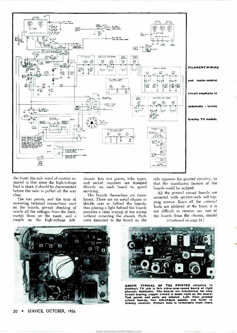
the front; the only word of caution re- quired is that since the high -voltage lead is short, it should be disconnected before the tube is pulled all the way clear.
The test points, and the type of mounting terminal connections used on the boards, permit checking of nearly all the voltages from the back, except those on the tuner, and a couple on the high -voltage sub -
chassis. Key test points, tube types, and socket numbers are stamped directly on each board to speed servicing.
The boards themselves are trans- lucent. There are no metal chassis or shields over or behind the boards; thus placing a light behind the boards provides a clear tracing of the wiring without removing the chassis. Parts were mounted to the board on the
FILAMENT WIRING
and motor -control
circuit employed in
automatic - tuning
Crosley TV models.
side opposite the printed circuitry, so
that the translucent feature of the boards could be utilized.
All the printed circuit boards are mounted with quarter -inch self -tap- ping screws. Since all the external leads are soldered at the front, it is
not difficult to remove any one of
the boards from the chassis, should (Continued on page 61)
ABOVE: TYPICAL OF THE PRINTED circuitry in Crosley's TV sets is this video -sync -sound board of rigid phenolic laminates. The boards are translucent for easy circuit tracing; copper circuit is made right on the board. Test points and parts are labeled. Left: Four printed circuit boards, two sub -chassis panels, and tuner in Crosley receiver. Picture tube is removable from front.
20 SERVICE, OCTOBER, 1956
www.americanradiohistory.com

TD sm
1
I.135v 0
I2,t,º
1330
P3- ó D6x E
ICJ02+ - L- _ <
-1(- aw
R302
0303
euzz CONTROL
r'Q},' 1
llh T301 "12BY71NSx~
~ºG316 Ì
vÑDEO L 0319 22
Rqa' x
.2,4K Ró v0 I -I, vJti
º r+ 0 `
onnu
-C3.002.7 TG3
12,
T1 L3w º '
, RE
8305
OM
06
11 B Ñ6DE i
pIIRV1
I or. L30
'6FD LJO. t0sB "r ; rJ0 I I
L--= ---J Rgoa 3º CJm_L3iJ 8J06
M1+ fÓ .BMCT Qnx
8325
L
TAP
C108
330 oUTPU
v115 121310 AU010 OUTPUT
Cr I ]0 "0
- VOLUME R307 CONTR9L á::
R 15 I
x R1YL 1 D G r-D. 0103313
TONE
J
3312
ör1.5
Çq3B1
R1e NEC
L30';
R321
0R R9 i RV4
I' 2T 1 a- '2 sëMS ws
R3p0 260 v1a 6DN"
®
Ar0v L
C325
33 92.
R3l6 ' PICTURE
8333 GUARD fo AGG LEVEL CONTROL 3 es
339 VIDEO -SYNC -SOUND BOARD
4 TO "M VOLTAGE 0000315- - - 3826 ,¿
SÁ202
.-1C226 Tw.
rz01
on.E
' L_ "c_ -- L3ós RÌO]
mw IC20e f 1nº13
T °N,2°1D 12206
RZ18
0 1K
2 wR
COIS_ _Cz020 äRN
05.02
I HORIZONTAL BOARD
óó'ó k
vuo 3626 xD¿.
L303
8338
0323 0T32 ep
Cwf>R If I C330
1 R1u 3
11-35 °' 17° ái:.'' I 0
D
4
CONTRAST I
CONTROL
-Ó 1'31
>:DP i
VERT HOLD
rbrxc. 0 11 iiw ñ
C402 1
k!.
R30e L312 I
M '36_
10J009 I
ODU
SLN r101
D ell!
x
I n,
= 01 - J 1cw3c
R].Ix T11ºD swuel
13,11-
3327
TAP 0014
To TOTAVAL
1 -
TII ...3525 - 61.
210104 PICTURE TUBE
ROO
Mº . Owe
IL103
I=° -
FOCUS
nv TOT
11.1
R112
.11
Oros _I_
R1O9 º 1JE6
BNIGH iiESS
.' RxÓ
-- ONN -br.3 0401 ROOD
1°v 4 :n NEIGNT cáób
IGbS AA. D .Ñ41
T
NAOS
iY , 61130 R406 ;..F.¡
h 67 VERT OSG Rb:
1
1u 13800tOe -. ...
I.110 º 8j,¡j VERTICAL
Ai _ LINEARITY
EARLr Hrv PRODUCTION - SRorR16 VERTICAL BOARD ,,,,T 0y r.s 00TT 0 U11E5. --
133 STNC OJ 'I100 FI18.
- C1o91°r 1i1xN 8;.. T + ., 9D Ri9DD DpB D
rloz
vU3A Pr -G Doe
+r iC5T7 j Tr`^ çsa OUTPUT,
,
p9 R
Gb i 22 OT/ T
pN
01 w2ozüR 09
'i(e,. I rI 13
33066
N K
f4
IÉÓ' RiiÓOa
J HNRvY
OSNn.
J 1S
C216
LJ a
8203
n1 Lzos I w
os TRn
R=1`
Ohm
DUr
G51e 10.
85.
¿Dr VIDEO I F BOARD Acç _ _ - 3514
OI^' 6t
vlose 2 6CN7 0
CONTROL
1.501 _ Ìf1
ail
0509
I.260 v j
T 60G7 v112A RN 'z 100
J.,ºJ
1`ióa I" 1 T w6= d
L
MR
RM0, TCDSOT
240
C>11
R5«0 ORw
29 BC67
015.8116E
'I C219 i tO .603
-
rg
10221
1- 260 V
T51I
10513 1C 12 I
URN rit 1
T_011
730
RZN
á`
1.206 1
1GD0 r=-
IfflE V.
f: `120 R119 -: LA w I gN 6 aw
I wié 1 -3!!43 I
L_____ J
1
o- óT110 aouw ARo
CIRCUITRY of video if, video -sync -sound, vertical and horizontal boards, plus by chassis in Crosley 493 (code B)/494 (code A) chassis
used in '57 line of TV receivers.
SERVICE, OCTOBER, 1956 21
www.americanradiohistory.com

Simplified Convergence Adjustment
THE MOST difficult task facing Serv- ice Men in color -TV installation and service is making the necessary con- trol adjustments to achieve accept- able convergence. Acceptable con- vergence was almost an impossibility for the early 15 and 19 -inch color receivers, and until recent improve- ments occurred in picture tubes and convergence circuitry, 21 -inch color receivers were almost as difficult.
Convergence is so troublesome be- cause perfect convergence can never be achieved, due to component, cir- cuitry and manufacturing tolerances. Another contributing factor is that it is very difficult, until sufficient ex- perience is gained, to determine when an improvement is no longer pos- sible, or when acceptable results have been obtained during a particular step in the adjustment procedure. Even though these conditions exist, present 21 -inch color receivers can be adjusted so that the slight amount of misconvergence that is present will be unnoticeable at normal viewing distances, even by the most critical viewers.
Another important consideration concerning convergence adjustments
Step -By -Step Analysis For Static
And Dynamic Convergence Control
by KEN KLEIDON National Color Television Manager
Hycon Electronics, Inc.
(Left) FIG. 1: WITH HELP of color bar/dot generator* and Sylvania 21 -inch color receiver, author (kneeling) demon- strates convergence procedure to E. W. Merrian, Sylvania service manager (right) and D. Winters, Sylvania color
school director (left).
is the type of convergence generator used. Whether the signal used is rf
or video, the generator must supply sync which corresponds in frequen- cy to that of a station. The horizon- tal and vert, ai scanning frequencies of the receiver must be the same dur- ing convergence adjustments as when an air signal is received. If the gen- erator does not correspond, the dy- namic convergence waveforms devel- oped will differ and misconvergence will result.
After reviewing the convergence adjustment procedures contained in the service manuals of various color receiver manufacturers, it was found that the procedures varied consider- ably. The basic method was similar in each procedure, but the approach differed drastically. When examin- ing the convergence circuitry of each receiver, it was found that, except for a few, there were no major differ- ences and the same type controls were employed which affected the electron beam in an identical man- ner. The convergence circuitry of three color TV manufacturers ap- pears in Fig. 1, 2 and 3. It will be
.Htiron 616
noted that in Figs. 1 and 2, identical controls are used in every case. The dc or static convergence controls in one case are permanent magnets and variable controls in the other. The circuit in Fig. 3 employs the same type vertical controls with combina- tion red and green horizontal -con- vergence controls. In those receivers which were not similar, the differ- ences as far as an overall conver- gence adjustment procedure is con- cerned, were found to be only minor. Also, the convergence generator sug- gested in the instructions varied from that supplying white dots to a cross- hatch pattern to vertical and horizon- tal lines.
Since such a variation existed, and due to the fact that three -gun color - picture tubes will be in use for a con- siderable length of time, it was decid- ed to devise a practical convergence adjustment procedure that would ap- ply to the greatest majority of color receivers and that could be used by those who are unfamiliar with con- vergence procedures. The conver- gence adjustment procedure that re- sulted was a combination of existing
(Continued on page 45)
EXTREME RIGHT-COLOR CONVERGENCE PATTERNS (Figs. 5-12): Fig. 5 illustrates patterns obtained when red static convergence control is adjusted properly. Results of red vertical amplitude and red vertical tilt -control adjustments are shown in Fig. 6. It is im- portant to note the unequal separation between red and blue vertical lines at left, center and right sides as illustrated in Fig. 7. The red horizontal amplitude and horizontal tilt (phase control adjustment) must be set so that red vertical lines are equally separated from blue vertical lines across entire face of tube, as shown in Fig. 8. The blue static convergence control adjustments must be carefully made until the blue horizontal line in the center of the picture tube is separated below the green horizontal line by about ?,", as shown in next pattern; Fig. 9. Blue verti cal amplitude and blue vertical tilt -control adjustment results are illus- trated in Fig. 10. One should note unequal separation between blue and green horizontal lines in center at left, center and right sides, as shown in pattern in Fig. 11. Result of blue horizontal amplitude and blue horizontal tilt -control adjustments are shown
in Fig. 12; blue line is parallel to green line in center of tube.
22 SERVICE, OCTOBER, 1956
www.americanradiohistory.com

Procedure For COLOR -TV
Vert Tilt Convergence Yoke
¡- 0 pc]
Horiz Amplitude
Winding on HV
Xfmr
B+
Vert Tilt B o
P
Blue Lateral
Magnet
Cathode V Output Tube
Convergence Yoke r--
Vert Amplitude
Winding on HV
Xfmr
Vert Tilt Convergence Yoke r--
B I e DCI
1I1I ` IH B I Horiz Tilt
r I
DCI
( ODC Amplitude 'Will ' r
R
Winding on
HV Xfmr
Blue Red
ii./.:4 jI jI1nch
Blue Red
O 1
7
Ilk f Blue Red
Blue ,,,Red,
1 Il h i 4 Green
IL r Blue/ jl/4
i t
Green f r
BILe t
10
B lue atillal _______
Green
II //////
eGreen%%%j,/jam/
12
(Left) FIGS. 2, 3, 4 (TOP TO BOTTOM): Con- vergence circuitry of Sylvania 1-534.1
(Fig. 2;, RCA CTC5 (Fig. 3) and Westing- house 2292-1 models (Fig. 41.
SERVICE, OCTOBER, 1956 23
www.americanradiohistory.com

Fuse
Fuse
Fused Plu Power
9 Switch r-----1
b i FIG. 1: FUSING SET with fused plug. Cross-sectional view of typical plug is illustrated in (a). How the fused plug is connected in a line is shown In (b).
.--. E
EXCEPT FOR fusible resistors and lengths of wire used in filament cir- cuits, TV fuses are of the cartridge variety and come in various lengths. Cartridge fuses may have pigtails for soldering in the circuit or come with- out pigtails for insertion in a fuse clip or fuse holder. Replacement fuses without pigtails must be the same length as the old fuse to fit properly in the fuse clip or fuse - holder.
A dual -fuse clip (illustrated in the first installment of this report$, and in Fig. 2 in this report) may be used to replace a blown pigtail fuse with- out unsoldering the old fuse. One side of each clip is placed on each end of a replacement fuse without pigtails. The other side of the fuse clips is placed on each end of the blown pig- tail fuse. In this way, a new fuse can be inserted in the circuit without soldering. No metal parts in the new fuse connection should be close enough to the chassis or other compo- nents to cause possibly a short. This
`Author of Repairing Television Receivers; John F. Rider Publisher, Inc.
24 SERVICE, OCTOBER, 1956
TV Fuse Installation -Repair IIIIIIIIIIIIIIIIIIIIIIIIIIIIIIIIIIIIIIIIIIII IIIIIIIIII Itl 11l ll llllllll ll llli II IIII IIIIIIII III III II II II II II111111111 "" '111111""'.,1111I .
How To Use Fuse Plugs And
C (Quick Blow) and N (Slow Blow) Fuses
II II IIII "9IIIm '.11 11111111 111111111'1 11
by CYRUS GLICKSTEIN*
method of replacing a pigtail fuse should be used only if the old fuse is in a chassis area not easily accessible to the set owner.
The simplest method to insert a fuse in a set not having one is to install a fused plug. Fuses commonly used for this purpose are 3.2 -amp slow blow. The objection to this type of fusing is its accessibility to the set owner. On occasion, Service Men may want to install a fuse on the chassis.
As a guide to effective fuse -instal- lation procedure, one should follow the requirements set forth by the Un- derwriters' Laboratories, Inc., for fus- ing circuits to minimize the danger of shock and fire.
Up to very recently, a serious fuse problem in TV sets has been the com- plete interchangeability of cartridge fuses, regardless of current rating. As a result, fuses with too high a current rating are often substituted by error or otherwise, especially in sets where the fuses are accessible to the set owner. If the overfusing is great enough, the fuse is obviously
(Right) FIG. 2: SNAP-ON insulated fuse holder designed for replacement of TV pigtail fuses, which can remain in holder, while snap -type fuse is inserted in other side.
(Left) FIG. 3: TYPICAL TYPE N fuse ial and fuseholder (b). Type C fuses and holders are similar. The flanges (A) vary in width according to current rating; they match
slots in the holder.
[Illustrations courtesy Bussmann and Littelfuse.]
fThe first report on TV fuses appeared in the September issue of SERVICE.
!111111111111111111111111111111 IIIIIIIIIIIIIIIII
serving no useful function, and dam- age to the set or a fire may result. As a result of the initiative of UL, fuse companies are now producing fuse holders and associated fuses which safeguard against substituting the wrong size and type of fuse.
Two basic types of fuses are used: C (quick blow) and N (slow blow) .
The top cap of each fuse has two flanges, varying in width according to a small amperage range. Slots in the top of the fuseholder are made to match the flanges on the fuses for each specific range. In addition, three fuse lengths are used. Since fuses with higher current ratings have wider flanges, they will not fit into a fuseholder designed for fuses with a substantially lower current rating. In the same way, to avoid blowing caused by using a quick blow fuse where a slow blow one should be used, a type C fuse will not fit into a type N fuseholder of the same am- perage.
A C or N fuseholder can be in- stalled by inserting the holder in a
(Continued on page 43 )
4
www.americanradiohistory.com

MIN MI IliiBi IliMI Ili ® MI Ma MO liNZI NMI MIMI MI
11.-TOP MOUNTING INSULATOP
1
1
1
1
1
CUP THESE FOR REFERENCE
OTPOINT
TV
TUBE
CHARTS
Hotpoint TV, America's newest major TV line, is now in the stores.
Complete service information is now available from Hotpoint TV Distributors. If you have not yet ordered it, these tube charts give you basic service in- formation for use until your complete material arrives.
Published as a service to servicemen by
(A Division of General Electric Company)
5600 West Taylor Street Chicago 44, III nois
R167 BR1GHT-=
NESS
CONTR45TC
R305 VOLUME ON-Off
INSULATOR
CENTERING LEVERS ROTATE TO CENTER PICTURE.
YOKE CLAMP WING NUT VAS
L005ENW TURN 3AÚ6 YOKE TO CORRECT FOR PICTURE TILT. R209
HEIGHT, ION TRAP
ROTATE.MOVE FORWARD B BACKWARD FOR MAU. BRIGHTNESS WITHOUT NECK SHADOW.
OUNTING INSULATORS
CHASSIS HS-Q-56-Covers 14S203 in VHF and UHF models.
5250
rR2:11
R210
R271
monC=
-r
"...]DISTANT LOCAL V109
I
:0i ;0:0:0;, R211 VIF AVE
VERT LI
Models
AC INTERLOCK
iV111¡ EIx2A/
INSULATORTA
14S201, 14S202,
r owlc
6CF TI51 Ó 152
o
11°c
L152s.o am
68T7ss c.xc
cr ï
C307
O T 300
6ÁU6
T400
I 12001
T250
1B3GT
] R171. R178 F. sWss
311
CHASSIS HS-U-56-Covers Models 21S401, 21S451, 21S452, 21S501, 21S502, 21S551, 21S552, 24S801, 24S802 in VHF and UHF models.
TPIY
CONTRAST
R 74
VERTICAL
R207
BRIGHTNESS
R179
VOLUME
R306
1154
AUDIO I -F
VIDEO AMP
L152
ON-OFF 1ST I -F 5401 4725MC TRAPOL150
b PI L136
VNF TOUNER IFENronEl
ÌUHF I
I I
Ivloói I I\2AF 1 I
C
YOKE
T$- VERT OSC.
..T4-22 B OUTPUT
sIORIZ MV VIQ7 . 6CMT VITO TPn
6CG7 L250
HOR STAB R255 R208 R214
O O O HORIZ HEIGHT VERT HOLD LIN
HORIZ. OUTPUT DAMPER
0.- -.N. / V112
1%2A H V. RECTIFIER
CHASSIS HS-MM-56-Covers 17S302 in both VHF and UHF models.
10-13,216
Models 17S301 and
WM IBM WM MI MI UM Mil WM lffl MIMI IZM OM IM MN
SERVICE, OCTOBER, 1956 25
www.americanradiohistory.com

26
BE
The Tung -Sol Magic Mirror Aluminized Picture
Tube captures every tone, every detail brilliantly to bring out the best in every set. It's your best
insurance for loyal, satisfied customers. Tell your supplier you'd rather have Tung -Sol tubes.
*TUNG-SOL® Magic Mirror A'uminized
PICTURE TUBES TUNG-SOL ELECTRIC INC., Newark 4, N. J. Sales Offices: Atlanta,
Columbus, Culver City, Dallas, Denver, Detroit, Melrose Park (111.1,
Newark, Seattle.
SERVICE, OCTOBER, 1956
CATALOGS -LEAFLETS -BOOKS
EAGLE ELECTRIC_ MANUFACTURING Co., Inc., 23-10 Bridge Plaza South, Long Island City 1, N. Y., has released a 72 - page illustrated catalog covering electrical wiring devices, ex- tension and cord sets, fuses, lamps, wall plates, push buttons, flashing devices, lighters and elements, nichrome wire and elements.
0 0 e
ALLIED RADIO CORP., 100 N. Western Ave., Chicago 80, Ill., has published a 356 -page catalog, 160, listing more than 27,000 items. Has a special section devoted to high-fidelity equipment. Contains descriptive and technical data on TV chassis, boosters, rotators, uhf converters; table model and portable phonos; pa amplifiers and systems; industrial vhf radio and radiotelephone equipment; test equipment; compo- nents; hardware; tools and technical publications.
* o *
HOWARD W. SAMS AND CO., Inc., 2201 E. 46th St., Indianap- olis 5, Ind., has announced publication of Servicing and Calibrating Test Equipment by Milton S. Kiver. Chapters cover proper use of test equipment, methods for checking accuracy of instrument, keeping of test equipment opera- tional records, preventive maintenance and servicing. Has 192 pages; priced at $2.75.
e e e
NEWARK ELECTRIC Co., 223 W. Madison St., Chicago 6, Ill., has issued 308 -page catalog 65, with descriptive and techni- cal specifications on test equipment, tubes, hardware, capaci- tors, fuses, tools, audio equipment, resistors, transformers, connectors and relays.
O 0 0
MERIT COIL AND TRANSFORMER CORP., 4427 N. Clark St., Chicago 40, Ill., has published a 128 -page All -Industry Repl Guide, 409, with coil and transformer replacement informa- tion for approximately 20,000 models and chassis. Included is a 631 -page section with flyback schematics.
e * 0
THE RADIO -ELECTRONIC MASTER, 106 Lafayette St., New York 13, N. Y., has issued an illustrated industry -wide chart on panel and flashlight lamps. Chart lists numerically all panel and flashlight lamps manufactured by General Electric, National Carbon, RCA, Raytheon, Tung -Sol and Westing- house.
o 0 e
MCGRAW-HILL Boor( Co., INC., 330 W. 42nd St., New York 36, N. Y., has published an 832 -page Handbook of Semicon- ductor Electronics, edited by Lloyd P. Hunter. Appearing are data on transistor action; basic physics of electrical con- duction in solids; technological processes used in transistor and diode manufacture; and circuit design and applications for transistors, diodes and photocells, with information on low and high -frequency amplifiers and switching circuits, direct- ly -coupled amplifiers, transistor oscillators and circuits using special semiconductor devices. Priced at $12.
e e e
GENERAL ELECTRIC Co., Tube Department, Schenectady 5, N. Y., has released wall -chart TV -picture tube replacement guide ETR-702B, listing 223 types currently available. Chart details both aluminized and non -aluminized replacements, where available, for each type. Tube types are classified by size, base, bulb structure, external coating, anode contact, focus method, deflection angle, overall length, bulb diameter, neck length, anode voltage and type of ion -trap magnet. Color tubes are included. Available from distributors.
e e o
JOHN F. RIDER, PUBLISHER, INC., 480 Canal St., New York 13, N. Y., has announced a TV receiver single -diagram -only service, S -D -O, consisting of 17" x 22" sheets with schema- tics, service information, voltage data, tube layouts, align- ment information, trimmer locations, adjustments and parts lists. Sheets, which fold for filing, cover RCA, Philco, Ad- miral, General Electric, Emerson, Motorola, Crosley and Zenith sets produced during the past five years, including present production. Service is available through parts dis- tributors.
www.americanradiohistory.com

Associations
AL HAAS, head of the Television Service Advisory Council, inking joint proclamation between Council and WHYY-TV, Philadelphia's channel 35 station, calling for close teamwork adapting area sets so they can pick up uhf signals. Looking on: Paul Blanshard Jr., and Richard Burdick of WHYY and Morrie Green, local distributor
and Council member.
RTTA, Pasadena, Calif. HARRY COOLIDGE, president of the Radio -Television Tech- nicians Association of Pasadena has been elected delegate to the California State Electronics Association.
According to Ben Leff, RTTA publicity chairman, the association has made tentative plans to take a booth at the Pasadena Home Show, Nov. 16-18, 1956. An operating TV chassis, surrounded by 'scopes and meters, connected to major test points, is expected to be shown.
c c º NATESA, Chicago, Ill.
THE NATIONAL ALLIANCE OF TELEVISION and Electronic Service Associations has named Frank Moch to a newly created salaried office of executive director for a two-year period. Moch will also serve as a member of a 12 -man executive council which includes: Robert Hester, president; F. B. Koepnick, secretary general; and C. Nelson Burns, treasurer. Albert C. W. Saunders has been retained as educational director.
a o *
RTG, Long Island, N. Y.
ON SUNDAY, DEC. 9, following the three-day electronics fair of the Radio and Television Guild, Long Island, N. Y., the group will sponsor a national conference of service associa- tions to discuss current industry problems. Arrangements are also being made to have the national service managers from leading manufacturers participate in a panel discussion on "What does the friture hold for the independent service business?"
TEN YEARS AGO IN SERVICE
TALKS ON independent scrV icing and TV installation -repair, featured at the annual conference of the Television Broad- casters Association in New York, stressed overwhelming approval of the independent Service Man and his ability to take care of TV receivers. Manufacturers indicated that they would set up schools to train Service Men and subsequently would authorize those who complete the courses successfully to take care of their servicing work. Associations, it was noted, would be asked to send members in for these special courses.... First of a series of exclusive reports on indus- trial intercom was published in SERVICE.... Roy S. Laird, Ohmite, was elected chairman of the Association of Elec- tronic Parts and Equipment Manufacturers; Les A. Thayer, Belden, vice chairman. . . . Dick Morris was appointed general sales manager of Snyder. . Charles Golenpaul, Aerovox, and Walter Jablon, Hammarlund, were named di- rectors of the 1947 Radio Parts and Equipment Trade Show.... A volume control, said to be smaller than a dime, was announced by Centralab.... Don G. Mitchell, president of Svl\ named to tlic National Distribution Council.
EST i N
ND Made to the highest requirements of leading set
manufacturers, Tung -Sol Tubes are perfect re- placements for all sets. Bank on Tung-Sol's brand of quality-tops in the industry. It's the sure way to avoid callbacks that eat into profits. Tell your supplier you'd rather have Tung -Sol tubes.
c
.,Jfj¡ ` / ¡ s CULfj lrTIIG .% "''.... / TONG -SOLI'
RECEIVING TUBES TUNG-SOL makes All Glass Sealed Beam Lamps, Miniature Lamps
Signal Flashers, Picture Tubes, Radio, TV and Special Purpose
Electron Tubes and Semiconductor Products.
SERVICE, OCTOBER, 1956 27
www.americanradiohistory.com

FIELD AND SHOP NOTES
Industrial ... Commercial ... Institutional
Communications ... Audio . , . Television
4 9 Installation ... Maintenance . .. Repair
A Report on a Commercial Mobile Tape -Phono Sound Truck With a Two -Way System
LEADING THE \ I \HDI GRAS parade in New Orleans this year was an inno- vation in mobile public-address serv- ice: a complete 2 -way high-fidelity unit on wheels.$ Housed in a custom- built car, the unit features a tape sound system with a two-way tele- phone system.
Transmitted over the truck's pa system is a tape narration. Operators of the sound truck have reported that the tape has proven most satisfactory in operating in varied climate and weather conditions. The microphone input was altered to a low 50 -ohm impedance; input to a phono (also used in the truck) was set at a high impedance. For the reproduction of records, the phono player output can be fed to the phono input of the tape recorder.
Tape Output VC Circuit
While the output of the tape re- corder is normally a cathode -follower circuit, a special small volume -control
mixer circuit was built in; two 500,- 000 -ohm gain controls, with 250,000 - ohm isolation resistors were used. One gain control was connected to the output of the tape recorder; the other was connected to the grid input of the first audio tube of the car radio. This was found to allow for independent volume control of not only the tape recorder, but a radio chassis over the loudspeaker system. The output of the volume control mixer was connected to the high -gain input of the power amplifier, serving as a bridging circuit.
Ample current to operate the equipment involved was a prime requisite in the sound car, so the standard generator was replaced with a 100 -ampere alternator. An out- put of 18-v ac (at motor idling speed the frequency is approximately 45 cy- cles) is rectified via a three-phase selenium rectifier attached to the fender firewall. The resulting 12-v dc
$Owned by the Miller Brewing Co., Milwaukee, Wis.
serves to keep the standard battery fully charged.
An additional 400 -ampere hour, 12-v battery was placed inside the car and wired with the regular bat- tery, giving approximately 500 am- pere battery service without the car motor running. A three-phase, 18-v transformer was attached to the out- put of the alternator. The output of the transformer secondary is rec- tified to produce 120-v dc with 800 - watt capacity.
Installation of the public address system and tape recorder required more than five months.
Rack -Mounted Facilities
The magnetic tape recorder can be used while the car is in motion. Mounted in the conventional rack and panel manner, the recorder can be set to tape material from the loudspeak- er system, radio or phono. By using intercomponent switches material to
(Continued on page 55)
ABOVE: CUSTOM-BUILT car which features a complete public-address sound and 2.way radio system. At right is sound track tape recorder designed to be used to record voice announcements over the loudspeaker, phono records or radio. The recorder can be used while the car is in motion, and recordings played back directly through the loud speaker. While recording it is not neces-
sary to have the material go through the loudspeaker. (Courtesy Miller Brewing Co.)
28 SERVICE, OCTOBER, 1956
www.americanradiohistory.com

The Equation that Shook the World!
® Registered in U. S. Patent Office
A hasty scrawl on a scrap of paper ushered in the Atomic Age. Through this equation, Dr. Albert Einstein revealed to mankind the awesome secret of atomic fission, with all of its tremendous power for good or evil.
This is the kind of a world we live in ... a world where knowledge is power in a truer sense than ever before. It is an exciting world.
Univac® has added a new dimension to the world of science, process- ing data with a speed that crowds many lifetimes of research into a few hours.
Squarely in the midst of this exciting world are the engineers and scientists of Remington Rand Univac. Their potential for growth and achievement (and the rewards that go with them) is unlimited. You can be one of them.
Immediate Openings for: FIELD LOCATION ENGINEERS with a college degree in a scientific or engineer- ing field and experience in electronics. Extensive electronic background may sub- stitute for some college. Many opportunities for rapid advancement.
FIELD LOCATION TECHNICIANS with technical school background and prefer- ably some experience in electronics. These positions can lead to full engineering responsibility.
Send complete resume to:
7lund 7iii_a occ DIVISION OF SPERRY RAND CORPORATION
Mr. Phil Wilson Dept. SO -28
1902 W. MINNEHAHA AVENUE ST. PAUL W4, MINNESOTA
SERVICE, OCTOBER, 1956 29
www.americanradiohistory.com

(Left) FIG. 1: PHILCO dynamic diode discriminator. Circuit at right of AA is the demodulator section; circuit at
left is responsible for AM reduction.
(Above) FIG. 2: BLOCK DIAGRAM of diode system, illustrat-
ing overall operation.
Dynamic Diode Discriminator
An Improved System of Sound Detection In TV Chassis
IN THE IDEAL CASE, the design phi- losophy of a frequency -modulation demodulator desires that the two functions, amplitude -modulation re- duction and frequency -modulation demodulating, be accomplished by different circuits. This is desirable, because in a device which accom- plishes both functions with common elements, there will exist a region of operation where the action of AM re- duction will also prevent any output of the FM signal. The ratio detector is an example of a system which suffers this drawback. It is also re- quired that the AM reduction action be self adjusting to different levels of input signal.
To meet the ideal conditions, with the added advantage of AM limiting at the highest signal level available and at a relatively high impedance, the circuit shown in Fig. 1 was developed. Termed the dynamic diode discriminator, this circuit performs the functions of AM reduction and FM demodulation in two distinct parts of the system.
Demodulation Action
Referring to Fig. 1, the portion of the circuit to the right of AA consti- tutes the demodulator section. This circuit is a conventional FM discrim- inator. The only feature here is the addition of the tertiary winding, which provides a dc return for the diodes and also a means of adjusting
30 SERVICE, OCTOBER, 1956
by R. H. OVERDEER Television Section, Engineering Department, Philco Corporation
the primary voltage impressed on the secondary. It is important to realize that the choice of discriminator type is arbitrary and not limited to this particular type.
The circuit to the left of AA is re- sponsible for AM reduction; this is the dynamic diode from which the circuit takes its name.
AM Suppression
To simplify an analysis of the operation of the AM suppression cir- cuit, the block diagram in Fig. 2 has been prepared.
The model shown in Fig. 2 consists of a parallel lc circuit with a black box connected across its terminals. Three conditions of operation obtain here: When the signal across the lc tank is constant, the box acts as a constant resistive load; when the signal suddenly increases across the lc tank, the resistance of the box de- creases; conversely when the im- pressed signal suddenly decreases, the box resistance increases. It can be seen that this action will tend to hold the signal across the tank constant, since the effective Q is varied in- versely as any short time change in the input signal.
Comparing the relationship of Fig. 2 to Fig. 1, we have the black box
of Fig. 2 representing the diode and its rc load in Fig. 1. The rc load, which biases the diode to the peak value of the impressed carrier, acts as a level -sensing device and, by con- trolling the conduction of the diode, varies the resistive load across the lc circuit from R/2 to a low value de- termined by the perveance of the diode.
This action serves to remove any upward or downward amplitude mod- ulation which appears on the positive cycle of the carrier. Amplitude mod- ulation occurring on the negative cycle is removed by the filter action of the lc circuit. Since it is not loaded during this portion of the cycle by the diode, and the Q is high enough only since waves can exist across the tank and the amplitude modulation is removed.
The damping action of the dynamic diode imposes several requirements on the design of the circuit. The Q of the primary must be as high as prac- tical for best AM reduction and is limited only by stability requirements. The dynamic diode effectively broad- ens the bandwidth of the primary and for best thermal -noise performance, the bandwidth of the signal ahead of the dynamic diode discriminator must be limited.
www.americanradiohistory.com

New RCA WR -46A Video Dot/Crosshatch Generator. Produces stable, sharp patterns at high-level video
output for convergence adjustments.
Saves installation time; en- ables more precise con- vergence adjustments.
PRICE...
$179.50'
Magnified view shows sharply defined Dot pattern produced by WR -46A on typical picture tube.
high-level video output permits direct connec-
tion to grid or cathode circuits of color picture tubes-eliminates pattern distortion which may be
caused when generator signals are fed through rf, if, or of channels-results in clean, extremely sharp
pattern display permits simultaneous display.of pattern with broadcast picture in background to
assure that convergence adjustments are made at
correct horizontal and vertical scanning rates
switch -selection of four types of patterns is pro- vided: "V" bars for vertical dynamic tilt and ampli- tude convergence adjustments; "H" bars for hori- zontal dynamic phase and amplitude convergence; Crosshatch for simultaneous check of "V" and "H" convergence adjustments; Dots for center -screen
static -convergence adjustments and for "touching up" dynamic convergence has Brightness Equal-
izer Control for "V" and "H" elements in cross-
hatch pattern vertical sync is frequency -divided from horizontal sync, resulting in interlaced scan-
ning and exceptional freedom from "jitter", "crawl", and "sync -hunting" light weight portable.
S4)»pg1 .geemettip aken/Setvicei RCA WR -61B Color -Bar Generator.
Provides crystal -controlled signal source for trouble -shooting, and adjusting color -phasing and matrixing circuits.
WR -61B simplifies the usually complex measurement of the
relative gains of the 3 chrominance channels (R -Y, B -Y,
G -Y). With the WR -61B the relative gains of these channels can be measured at the output of each demodulator stage.
This simplified method of measuring gain is possible be-
cause the subcarrier output of the generator is constant
for alt color -phase angles. Curve A shows WR -61B output as it would appear on a 'scope, Curve B shows the output signal of one of the demodulators.
Outstanding features of WR -61B: generates signals for producing 10 different color -bars simultaneously-includ- ing bars corresponding to R -Y, B -Y, G -Y, I, and Q, signals
excellent signal source for localizing trouble ahead of or following the 2nd detector accepted as a standard for checking accuracy of color -phasing in many TV sta-
tions and network operations light weight portable.
*User Price (oPtional)
A 1
PRICE...
$259.50*
RCA TEST INSTRUMENTS ARE AVAILABLE THROUGH YOUR RCA DISTRIBUTOR.
TEST EQUIPMENT RADIO CORPORATION OF AM ERICA, HARRISON, N. J.
SERVICE, OCTOBER, 1956 31
www.americanradiohistory.com

UHF -VHF ANTENNA DIGEST DESIGN APPLICATION INSTALLATION SERVICE
Apartment -House TV-Distribution Systems For Fringe Areas
THERE ARE THREE basic types of TV distribution systems in use today. The first, and by far the most popular, is the local -area, multiple -outlet system used in hotels, large apartment build- ings, and in some motels. Next is the city-wide subscription system used in shadow -areas. This type usually de- pends upon a group of antennas and channel boosters on top of a nearby hill to pick up and amplify signals which are then fed on a cable to subscribers in the town or village in the valley. Both of these systems exist in many forms, and some have developed to a high degree of relia- bility, fidelity, and relative economy. Several manufacture a complete line of distribution components which are especially engineered for these sys- tems.
The third system is the fringe area, limited outlet type for multiple -dwell- ings or apartment houses outside the secondary service areas, that has its own set of requirements. Speci- fically, this fringe area encompasses a distance range of 60 to 100 miles from vhf stations. A distribution sys- tem is necessary here because satis- factory reception can be obtained only by an installation of large, high - gain antennas on the top of a tall pole or tower. Obviously, the installation of several such antennas and towers is not practicable on the roof of a single apartment building.
The fringe -area distribution system has the following general require- ments. It must have a good signal-to- noise ratio on all the promised chan- nels. In most fringe areas, the term good reception is rather loosely used, but here the signal-to-noise perform- ance of the distribution system obvi- ously must be as good, and in general
by LOUIS E. RABURN
somewhat better than that of residen- tial installations in the same fringe area. The system also must have good reliability; not only so that the service expenses are reasonably low, but also so that subscribers are not often disappointed when they turn on their sets to watch scheduled TV programs. In addition, the cost of installing the system, adding tap-ons, and routine preventive service must all be reasonably low. It has been found desirable to employ an electric - clock timing arrangement to switch the system on only when the stations are on the air. This not only spares the amplifier tubes, but also saves needless power consumption. Finally, it is sometimes necessary to equalize the signal levels in the different chan- nels to avoid overload distortion and inter -channel coupling. There is usu- ally no requirement for special com- pensation due to the variation of the distribution cable losses with frequen- cy. These cables are not long enough to have appreciable loss at even the highest vhf frequency.
Outdoor Components
The most important of the outdoor components is the antenna. It must have high gain throughout its own channel and must be rugged enough to perform in the worst extremes of wind, rain and sleet. Since it is usu- ally convenient to cover the station in each channel with a separate an- tenna, the yagi-type antenna has been found to be the most suitable; it is generally best to choose one with
at least eight or nine elements and stabilizing angle braces. It may be necessary in some areas to receive two stations in the low band or two stations in the high band. It is then possible to use a single high -gain broad -band antenna quite satisfactor- ily if low noise preamplifiers, which can cover the required excess band- width without degradation in signal- to-noise ratio, are used.
The next important component is the channel preamp which should be located on top of the antenna tower near the feed terminals of the anten- na and far from the high -noise area arourtd the apartments. The preamp should have the best possible signal- to-noise ratio, such as that provided by a cascode circuit or some equiva- lent design.
The leadin from the channel pre - amp should be shielded to prevent pickup of ignition noise and other extraneous signals by the leadin. Pickup on this leadin is quite pos- sible, even though the preamp may boost the antenna signal on the order of 10 or 20 db; voltage gain of ap- proximately 3 to 10. A variety of suitable leadin cables in single lead coax and balanced two lead twin -ax forms are available for this purpose. The other leadin requirement is that it be designed and installed to pro- vide reliable service without corro- sion or increase in attenuation after prolonged exposure to the elements.
The supporting tower for the out- door components must be stable and reliable. It should have a height of at least 20' to 30' above the apart- ment house roof. The main reason for this minimum height is not to pro- vide an increase of the received signal but rather to move the antennas out
32 SERVICE, OCTOBER, 1956
www.americanradiohistory.com

of the high -noise level environment surrounding the apartment building. Naturally, the tower must also be high enough to place the antennas above nearby buildings and trees.
Indoor Components
The indoor components do not have any reliability problems due to weather conditions. However, dis- tribution amplifiers, which are usually necessary, do require some reliability consideration, since there are a multi- plicity of amplifier tubes with in- creased chances for outage. The amplifier should also provide sufficient branch outputs without appreciable distortion of the signals from the pre - amps. A moderately good input sig- nal-to-noise ratio is required so that the input noise does not degrade the signal-to-noise ratio of the preamps.
The branch distribution cables may be either of the shielded or the un- shielded balanced twin -lead type, de- pending upon the noise conditions near the cable runs of the apartment building. Obviously, if these cables must pass near electrically -controlled signs, furnaces, washing machines, etc., they should be shielded. Also, it is usually found that runs of perhaps more than 150' will be more likely to pickup noise; therefore, as a general precaution, they also should be shield- ed. There are two reasons for avoiding the use of shielded cables throughout a system: (1) More attenuation loss per foot in the shielded than the un- shielded cable, and (2) expense per foot and considerably more installa- tion expense per branch, if it has to be fished past a number of obstruc- tions or partitions.
There are obvious advantages to the use of small coax cable for the
To No I
Antenna
To No.2 Antenna
Leadin
!
Apartment Apartment
0 l A
Electric Clock-Switch
110V A C
Power ~,
* A C Power !- + TV Signals
\Pre Amp Power Supply
Distribution Amp ifier
A LOW-COST fringe -area TV -antenna distribution system.
secondary branch lines. However, this cable, while slightly less expen- sive than shielded twin -ax, is likely to result in a more expensive overall in- stallation when the costs of the matching transformers for feeding the balanced 300 -ohm terminals on the set are included.
The distribution setup shown in Fig. 1 illustrates a low-cost ($300 ex- clusive of secondary branches) type of system which has been found to provide good performance and ac- ceptable reliability. This system has been used with as many as three yagis, each feeding into a single -chan- nel preamp and then into a multiple - distribution amplifier.
The costs of stringing the sec- ondary branches depends to a great
extent on the type of building and the type of cable that is involved. It has been found that the cost of an average length of secondary branch, including the labor, is in the range of $20 to $30. An installation of this type can be profitable if at least five subscribers can be secured at a rate of $20 a month.
Special Problems
Two basic problems are usually en- countered in these installations: A sufficient number of prospective sub- scribers must be signed up to make the installation profitable; and the apartment house owner must be con- vinced that this system will satisfy
(Continued on page 67)
ANTENNA BUILT around an antenna - connecting delay line network said to maintain optimum impedance match to transmission line and a single lobe pat- tern throughout the vhf band. Line is essentially a balanced T section com- posed of inductive series elements and a capacitive shunt element. Mechan- ically, it is made up of the antenna element and four heavy -aluminum coils. (Topliners '40, '50, '60 and '70; Technical Appliance Corporation,
Sherburne, N. Y.)
CONICAL -V -BEAM all -aluminum con- ical designed for the replacement mar- ket. Butterfly clamps are all -aluminum, and elements are doweled tubular. Radiator assembly with swing clamp automatically position the elements. Snap -in, positioned -reflector assembly said to provide positive locking. (Quickies Q -2X (single bay), Q -4X (two bay stack) and Q -8X (four bay stack); Telrex Labs., Asbury Park,
N. J.)
ANTENNA utilizing a traveling -wave principle said to reinforce picture sig- nals electronically by providing for an equal flow of current in every dipole on each of the vhf channels. All but one of the antenna's elements are driven elements. Hairpin or fat dipoles replace conventional folded dipole; all elements are of folded construction, including the reflector. (Channel Master Corp., Ellenville,
N. Y.)
SERVICE, OCTOBER, 1956 33
www.americanradiohistory.com

Circuitry Report on RCA 21 -Inch
COLOR -TV Chassis
by J. A. MAY and W. H. FULROTH Commercial Service, TV Service Clinic, RCA Service Company, Inc.
THE LUMINANCE CHANNEL in the RCA 21 -inch color chassis', which performs the same functions as the video amplifiers in conventional black - and -white TV receivers, consists of two stages. The first video amplifier uses the pentode section of a 6AW8. The picture second detector output is applied between the grid and cathode of the first video stage. Output from the first video stage is taken from both the cathode and plate circuits. Luminance (the black -and -white sig- nal) is coupled to the second video amplifier grid from the cathode cir- cuit. Sync, agc voltage and chromi- nance information are derived from the plate circuit of this stage. A de- lay line between the first and second video amplifiers delays the luminance information so that it will arrive at the picture at the same time as the chrominance information. Because of its narrower bandwidth, compared with the luminance signal, the chro- minance signal normally would arrive at the picture tube at a later time than the luminance information. If the delay line were not used, the color picture would appear to have fringing or color ghosts.
The contrast control in these models is a variable resistor in the cathode circuit of the second video stage. Brightness is varied by chang-
'RCA CTC-5/CTC5N.
ing the operating level of the second video amplifier with a variable re- sistor in the grid circuit of the second video amplifier. The plate circuit of the second video stage is coupled to the cathodes of the picture tube. Varying the operating level of the second video amplifier changes the plate voltage, which thus varies the picture -tube bias and consequently, the brightness.
A horizontal -retrace -blanking cir- cuit is provided to prevent the ap- pearance of a vertical yellow stripe in the picture during a color program. This is accomplished by amplifying a horizontal retrace pulse in the hori- zontal -blanking amplifier and apply- ing the resultant voltage to the screen grid of the second video amplifier. This causes a positive pulse to appear at the picture -tube cathodes and cuts off the picture tube during horizontal - retrace time, preventing burst (which occurs during horizontal retrace) from appearing as a yellow stripe on the picture -tube.
Vertical -retrace blanking is accom- plished by applying a voltage from the plate of the vertical output stage to the plate of the second video stage. The result is a positive pulse at the picture -tube cathodes which blanks
$Initial report on these models, with complete circuit of basic chassis, ap- peared in September, 1956, SERVICE.
+385V SUPPLY
4300V SUPPLY
2 AMP . .
1600 1500 8, OHMS MFD
.7=5U4GBFOB ÌMFDRECT5U4GB
RECT
10 000 OHMS V
6.3V 2A
Y 6.3V 12A
ON-OFF SW
56,000 OHMS
.047 MFD
56,000 OHMS
INTERLOCK
115V 60,1, SUPPLY
the picture -tube during vertical re- trace time.
The chrominance channel in the Special and Super series consists of a bandpass amplifier (the pentode section of a 6AW8) and the demodu- lators, two type 12AT7 dual triodes.
The bandpass amplifier is tuned to amplify the portion of the composite color -TV signal appearing about the region of the color-subcarrier fre- quency and receives signal from the plate circuit of the first video ampli- fier.
Chrominance drive to the demodu- lators, the burst (the color sync sig- nal) are derived from the plate cir- cuit of the bandpass amplifier.
The signal appearing in the side - bands of the color subcarriers is fed to the grids of the four triodes in the demodulator circuit. A locally -gen- erated 3.58 -mc cw subcarrier signal is fed to the cathodes of the demodu- lators from the 3.58 -mc cw-output transformer. The transformer is tuned so that the B -Y demodulator tube is fed a cw reference signal differing in phase by 123° from the cw reference signal fed to the G -Y demodulator. Cancellation of the 3.58 -mc cw signal takes place in the grid circuit of the demodulators, and output at the plate circuits consists of the color difference signals + (B -Y), - (B -Y), + (G - Y) and - (G -Y) . The R -Y color dif- ference signal is developed by mix- ing portions of the - (B -Y) and - (G -Y) signals.
Sufficient output is available from the demodulators to drive the grids of the picture -tube directly. Direct coupling is used to affect dc restora- tion and maintain color balance. Color synchronization is maintained by the burst keyer, burst amplifier,
(Continued on page 56)
(Left) LV POWER SUPPLY of 21 -inch RCA
color -TV models.
34 SERVICE, OCTOBER, 1956
www.americanradiohistory.com

with exclusive interceptor discs
An INDOOR ANTENNA
with OUTDOOR
EFFICIENC V
COMPLETE KIT $ 9 AX -100A Nothing Else to Buy
1 MAST SECTION; 3 WALL STANDOFF INSULATORS
35' TWIN -X CABLE; 1 ADJUSTABLE MOUNTING BASE
ATTENTION TECHNICIANS! 1st time in electronic history a 1/2 wave length resonant
antenna with only a t/a wave length physical dimension.
exuum
J
JOBBERS! LOOK M
THESE SALES FEATURES
,/ Makes every building contractor
market for built-in antennas
Opens a big replacement market
J Offers an exclusive "hideaway"
stallation
Handles easily because of light weight
and small size
Recommended for METROPOLITAN
and
SUBURBAN areas within 20 miles of
television stations
a
in-
2MANUFACTURING CO. PHILADELPHIA LOS ANGELES TORONTO
SERVICE, OCTOBER, 1956 35
www.americanradiohistory.com
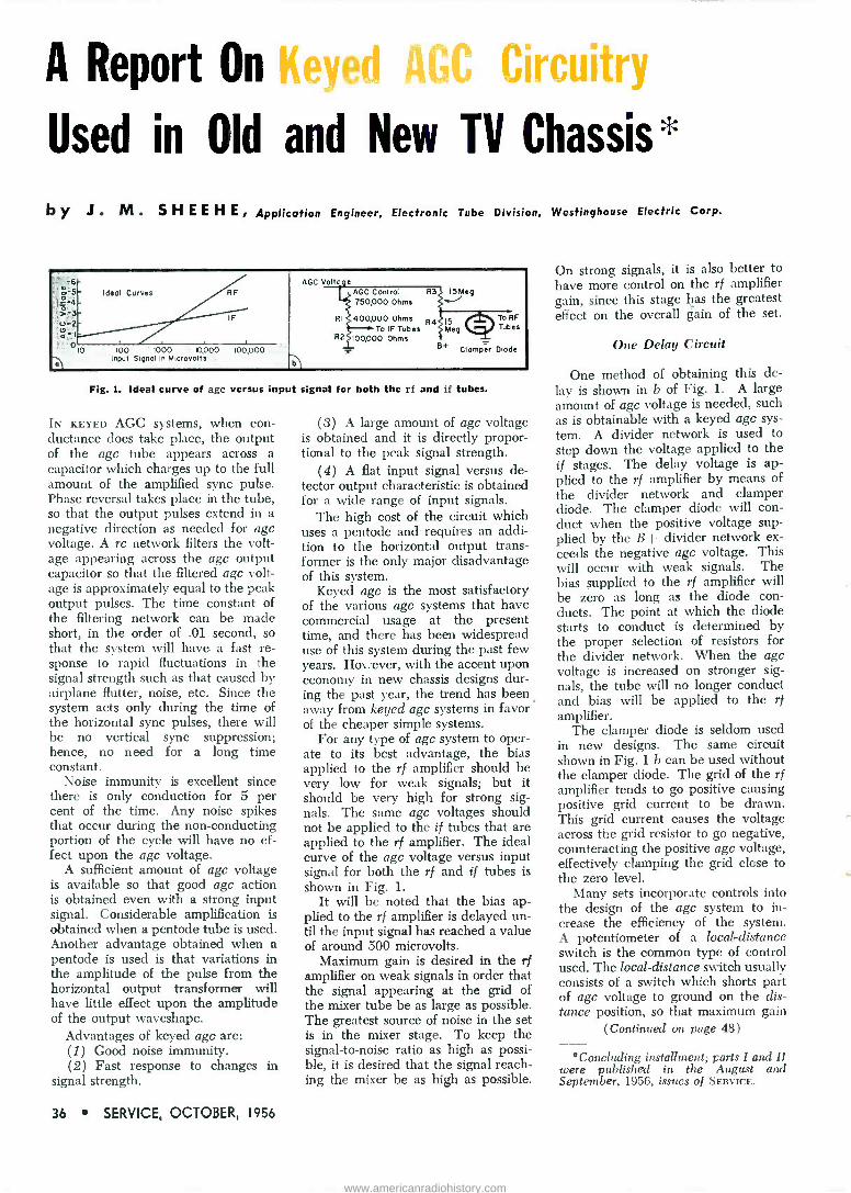
A Report On Keye 4Circuitry
Used in Old and New TV Chassis=
by J. M. S H E E H E r Application Engineer, Electronic Tube Division, Westinghouse Electric Corp.
.-5 Ideal Curves
-3 u -2 o
0 0 100 1000 10,000 100,000
Input Signal In Microvolts
AGC Volto.e AGC Control 750,000 Ohms
R3 1.5Meg
RI 400,000 Ohms R4 To IF Tubes
R2 100,000 Ohms
15 Meg
To RF Tubes
B+ Clamper Diode
Fig. 1. Ideal curve of agc versus input signal for both the rf and if tubes.
IN KEYED AGC systems, when con- ductance does take place, the output of the agc tube appears across a capacitor which charges up to the full amount of the amplified sync pulse. Phase reversal takes place in the tube, so that the output pulses extend in a negative direction as needed for agc voltage. A rc network filters the volt- age appearing across the agc output capacitor so that the filtered agc volt- age is approximately equal to the peak output pulses. The time constant of the filtering network can be made short, in the order of .01 second, so that the system will have a fast re- sponse to rapid fluctuations in the signal strength such as that caused by airplane flutter, noise, etc. Since the system acts only during the time of the horizontal sync pulses, there will be no vertical sync suppression; hence, no need for a long time constant.
Noise immunity is excellent since there is only conduction for 5 per cent of the time. Any noise spikes that occur during the non -conducting portion of the cycle will have no ef- fect upon the agc voltage.
A sufficient amount of agc voltage is available so that good agc action is obtained even with a strong input signal. Considerable amplification is obtained when a pentode tube is used. Another advantage obtained when a pentode is used is that variations in the amplitude of the pulse from the horizontal output transformer will have little effect upon the amplitude of the output waveshape.
Advantages of keyed agc are: (1) Good noise immunity. (2) Fast response to changes in
signal strength.
36 SERVICE, OCTOBER, 1956
(3) A large amount of agc voltage is obtained and it is directly propor- tional to the peak signal strength.
(4) A flat input signal versus de- tector output characteristic is obtained for a wide range of input signals.
The high cost of the circuit which uses a pentode and requires an addi- tion to the horizontal output trans- former is the only major disadvantage of this system.
Keyed agc is the most satisfactory of the various agc systems that have commercial usage at the present time, and there has been widespread use of this system during the past few years. However, with the accent upon economy in new chassis designs dur- ing the past year, the trend has been away from keyed agc systems in favor of the cheaper simple systems.
For any type of agc system to oper- ate to its best advantage, the bias applied to the rf amplifier should be very low for weak signals; but it should be very high for strong sig- nals. The same agc voltages should not be applied to the if tubes that are applied to the rf amplifier. The ideal curve of the agc voltage versus input signal for both the rf and if tubes is shown in Fig. 1.
It will be noted that the bias ap- plied to the rf amplifier is delayed un- til the input signal has reached a value of around 500 microvolts.
Maximum gain is desired in the rf amplifier on weak signals in order that the signal appearing at the grid of the mixer tube be as large as possible. The greatest source of noise in the set is in the mixer stage. To keep the signal-to-noise ratio as high as possi- ble, it is desired that the signal reach- ing the mixer be as high as possible.
On strong signals, it is also better to have more control on the rf amplifier gain, since this stage has the greatest effect on the overall gain of the set.
One Delay Circuit
One method of obtaining this de- lay is shown in b of Fig. 1. A large amount of agc voltage is needed, such as is obtainable with a keyed agc sys- tem. A divider network is used to step down the voltage applied to the if stages. The delay voltage is ap- plied to the rf amplifier by means of the divider network and clamper diode. The clamper diode will con- duct when the positive voltage sup- plied by the B-1- divider network ex- ceeds the negative agc voltage. This will occur with weak signals. The bias supplied to the rf amplifier will be zero as long as the diode con- ducts. The point at which the diode starts to conduct is determined by the proper selection of resistors for the divider network. When the agc voltage is increased on stronger sig- nals, the tube will no longer conduct and bias will be applied to the rf amplifier.
The clamper diode is seldom used in new designs. The same circuit shown in Fig. 1 b can be used without the clamper diode. The grid of the rf amplifier tends to go positive causing positive grid current to be drawn. This grid current causes the voltage across the grid resistor to go negative, counteracting the positive age voltage, effectively clamping the grid close to the zero level.
Many sets incorporate controls into the design of the agc system to in- crease the efficiency of the system. A potentiometer of a local -distance switch is the common type of control used. The local -distance switch usually consists of a switch which shorts part of age voltage to ground on the dis- tance position, so that maximum gain
(Continued on page 48)
°Concluding installment; parts I and II were published in the August and September, 1956, issues of SERVICE.
www.americanradiohistory.com

Q MUST for Accurate TV Service at a Profit
Phtkto : ,e y.a cu
Model 6500
PHILCO® Se'u'ice Kütq Pinpoints chassis or picture tube trouble
...without removal from cabinet At last, a multi -purpose instruxnel: that simplifies service and saves you time and money. Completely eliminates the :ask of removir_g chassis or picture tube from the cabinet for trouble shooting. Tells whether troulle is in the chassis or picture tube. Permits checking new CR tules without removal from original cartons. The Philcc "Service King" is available now at you: Philco distributor.
Tests both color and black and white picture tubes and receivers Clears picture tube shorts Aids in f etting up color purity, white balance and matrix circuits Measures DC voltage, anode voltage and resistance.
PHILCO UNIVERSAL COLOR BAR
AND DOT BAR GENERATOR A single, compact instrument that puts you
in the color .TV service business New, highly efficient and compact. Designed to provide the widest possible variety of functions. Unmatched for trouble shooting of circuits associated with color reproduction, and making accurate convergence adjustments in any color receiver made. In conjunction with your present monochrome equipment, it gives you complete color service facilities.
Write for FREE brochure on the complete line of Philco test equipment today.
PHILCO TUBES IMPROVE THE
EItOIMAMCE OP ANT TV OR
RATIO IICIIYEI
PHILCO CORPORATION ACCESSORY DIVISION PHILADELPHIA 34, PENNA.
QUALITY /
SERVICE, OCTOBER, 1956 37
www.americanradiohistory.com

Servicing Helps Leakage Control Factors in Bantam Electrolytics Used in
Transistor Amplifiers .. .
imuummuumiru umum!uuwm mm uu m r,r111.uuuuu ;,,;mmmuuunruuuuuuuuuuniiiiuuuwimuuuuuuuuuuuuumumiuuiiiuuuumuuuuuuunuuuuuiuiiuiuimuumuunimuum
IN LOW -FREQUENCY transistor ampli- fiers bantam electrolytics serve as coupling devices between stages. In tube circuits, a fixed capacitor is the rule for rc coupling; in transistorized equipment, the electrolytic is the rule rather than the exception. A tran- sistor amplifier illustrating typical coupling circuits is shown in Fig. 1. Here we find an electrolytic capacitor C, coupling a signal into transistor Tr,, and another capacitor C2 feeding the output signal of Tr, to the input of Tr,.
The circuit in Fig. 1 does not differ appreciably from a conventional tube circuit except for C, and C2. But the electrolytic is not just plain capacity; it has shunt leakage, as illustrated in
Fig. 2. At left the capacity is shunted by a leak resistance; this character- istic must be kept in mind whenever the electrolytic symbol (on right of Fig. 2) appears in the diagram.
Small subminiature electrolytics have the same capacity, power factor, and dc leakage qualities. In transistor coupling circuits, leakage may mean far more than capacity in determining the behavior of the circuit. To illus- trate, let us take the capacitor C, of Fig. 1 and redraw the coupling cir- cuit, as shown in Fig. 3. Now, we have a resistor RC, with which to reckon. The collector of transistor Tr, will run at nearly the battery po- tential; the base of transistor Tr, will he biased to about 1 volt by the ac-
nVO
3.dIF 1r;64 na.zr 1
119 RI 10,000 Ohms
TRI
0 10 7
2Mfd
220,000 Ohms
133 0000 Ohms
TR 2
2N107
F4 L20,OW Ohms
R5 0,000 Ohms
FIG. I (LEFT): Typical two -stage transistor- ized audio amplifier employing electrolytic
coupling capacitors.
FIG. 3 (RIGHT): Sec- ond stage coupling of Fig. 1 redrawn illus- trating the leakage
across capacitor Co.
O+
o -
FIG. 2: EQUIVALENT circuit of electro- lytic (left) contrasted to schematic sym-
bol (right).
tion of R,, primarily. RC, will be rather high for a good capacitor, in the vicinity of a megohm.
Now suppose the leakage of RCZ lowers to around 220,000 ohms. The base of Tr, thus has an additional bias path, the bias being about -2v instead of about 1 as intended. The operating load line of the transistor will shift, resulting in distortion or peak clipping; also an increased col- lector current of Tr, obtains, even if distortion does not become disagree- able, and the battery will wear out sooner. The circuit of Fig. 3 redrawn with the interelectrode resistances of the transistors drawn in to illustrate
(Continued on page 42)
IF YOU WANT THE BEST IN TV SERVICE INFORMATION
ON RCA PHILCO ADMIRAL EMERSON
GE CROSLEY
MOTOROLA ZENITH
(other manufacturers later on)
...ASK YOUR 1066Eß ABOUT
RIDER'S NEW
SDO (^5in9ia diagram eriiy ")
ONLY SOS PER CHASSIS!
38 SERVICE, OCTOBER, 1956
www.americanradiohistory.com

keep operating temperatures down-dependability up!
RCA SELENIUM RECTIFIERS utilize modern design --full surface ventilation with no chance of center -core hot -spots. Note the corrugated spring -steel separators which provide positive multiple -area contacts with each plate. This open construction facilitates free -flow of air and efficient cooling of the plates, and mini- mizes the possibilities of overheated components in compact TV, radio, and phonograph designs.
The one-piece assembly -yoke with the molded mounting stud prevents twisting or squeezing the stack during installation. Rigid construction minimizes the possibility of "barrier" breakdowns-gives greater assurance of dependability in operation.
So, when you need a replacement selenium rectifier, ask your distributor for a dependable, long life RCA SELENIUM RECTIFIER Available now in 12 types, ratings from 65 Ma to 500 Ma.
lei SELENIUM RECTIFIERS Radio Corporation of America Harrison, N. J.
590 ma compact) ,211G1
400 ma (compact) 421061
SERVICE, OCTOBER, 1956 39
www.americanradiohistory.com

BUD HEBERT, announcer, in sound -an- nounce booth, located on front end of steel beams which hold stadium overhang.
FRED HOFFMAN at tape recorder controls.
NICK STEMMLER, WHtUN radio an- nouncer, at recording ebuipment used to monitor track commentary for daily
broadcasts.
The Vernon Downs Raceway
SOUND PLAYS an important role at the three-quarter mile harness -racing oval in Vernon, N. Y., serving not only to supply running information to the fans in the park, interim music and sports news, but intercom contact for management and guests.
The system features four separate telephone circuits, four intercom sys- tems and four independent pa systems ranging from a 12 -watt mobile unit with one speaker used at the starting gate to 125 -watt high -power boosters feeding hi -fidelity horns across the track in the infield.
Main Track Sound System
The main track system is powered by rack -mounted amplifiers'; a moni- toring speaker in the rack assembly enables operator to monitor or check the output of any booster am- plifier. Below monitoring panel are two preamplifiers' whose inputs and outputs can be changed with the flip of a switch if one in use fails; pre - amps are self -powered five -channel mixers having low impedance micro -
'Bogen.
'Bogen LOL; response is 20-15,000 cps ± 2 db.
'Bogen H0125.
phone inputs; these preamps have level -indicating meters so the level may be kept down to about 0 db. It is possible to mix the outputs of four microphones and a phono pickup in any combination.
Its operation the tone control is held to near midposition so that minimum frequency attenuation appears on either end of the audio range; with the system used previously it was necessary to augment the bass re- sponse to give the sound body.
The rack also contains three booster amplifiers' each capable of 125 watts output, with a frequency response of 20 to 20,000 cps flat within 1 db. These amplifiers have been found very effective at the track where the background noise level rises as each field of horses drives at the finish line.
Conduit Line Runs
To expedite an efficient transfer of audio power from the amplifiers to the load in the infield, low -impedance twisted -pair lines (No. 12) were run in conduit under the track to terminate at the tote board. For impedance matching, constant -volt- age outdoor hi -fidelity transform- ers were installed; their use also simplified load calculations. The highest (16 w) tap was used on
E
Speaker, s
110 Feet
108 Feet TRACK
Apprournatery 600 Feet
150 Feet
STADIUM AREA
N
Speaker,
NUMBERS BOARD
50 Feet
TRACK
40 Feet
75 Feet
CLUB HOUSE AREA
w
SPEAKER LAYOUT on tote and numbers board at Vernon Downs track.
40 SERVICE, OCTOBER, 1956
www.americanradiohistory.com

Sound System by FREDERICK HOFFMAN
Features Hi-Fi Announce -Music and Intercom Networks
each transformer. These units have the added feature of taps down to .5 watt; in our case, though, each speak- er cluster was set up so it could be independently controlled by its relat- ed booster amplifier.
Main Area Speakers
The present speaker setup for the main area covered consists of five folded horns' which have a 1,000 - cycle lc crossover network. In the process of speaker placement, four of these units were tried on top of the tote board, in keeping with the single point source of sound principle; but it was found that even by employing brute force technique the sound ar- riving at the club house in the shel- tered area was pinched and weak. Although these horns are large (33" diameter) with good directional con- trol, facing them directly at the club house made slight difference; the dis- tance from the speakers was too great to provide adequate coverage.
Tests showed that each time the distance was doubled the pressure of the sound dropped 75% below its pre- vious level. The situation was recti- fied by placing two speakers near the club house in the infield, behind the numbers board, and another cluster of three -equally spaced on top of the tote board for the main stadium; these were connected to another am- plifier.
Care had to be taken in phasing and orienting these speakers (even though they were operated on sepa- rate amplifiers) to cut down the dis- tortion effect in the fringe area be- tween the club house and main grandstand, where the field of one set of horns was found to overlap the field of the other. A third booster3 was installed to feed speakers near the betting windows under the grand -
'University WLC. 'Shure 55S Unidyne. °Bogen RP -1.
'University PH.
[All photos by E. L. Boutilierj
stand and other speakers facing the main entrance and parking area to transmit event information to those coming into the park.
Club House Sound
Also on this line are club house dining room speakers, as well as an- other set which carry event an- nouncements to the paddock where the racetrack Marshall takes his place with a field of horses that enter the track for a parade preceding the race. Another booster is available to switch as a replacement for any defective unit which requires service.
Mike Platform
The announcer has a unique elbow platform (on which is mounted a microphones from which he can ob- serve the track; he can also swivel this platform at will. At the right of the announcer is a switch mounted so that it can be operated while holding binoculars; this elbow - operated switch is preceded by a switch on the pa operator's control panel which is normally off for phono use. Another low -impedance microphone cable runs to the winner's circle where an- other micrphone5 is used. A relay - operated precedence line runs to a switch at the junction box, so that if the winner's circle mike is needed
(Continued on page 53)
AMPLIFIER control panel and phono unit. Additional control equipment was added to rack after this photo was taken.
VIEW of two horns on numbers board.
(Below)
TOTE BOARD with three hi-fi bull horns.
SERVICE, OCTOBER, 1956 41
www.americanradiohistory.com

When .. You Change Your Address
Be sure to notify the Subscription Department of SERVICE at 52 Vander- bilt Avenue, New York 17, N. Y., giving the old as well as the new address, enclose address labels from your last SERVICE copy, and do this at least four weeks in advance.
The Post Office Department does not forward magazines unless you pay additional postage, and we cannot duplicate copies mailed to the old address.
We ask your cooperation.
YOU can easily service small appli- ances as well as TV and radio for extra profits. You're in the home, so no extra call is required. Just inquire if there's an iron, toaster, mixer or other appli- ance that needs attention. You'll be surprised how many will say "yes" and be glad you, mentioned it!
More Than 5 Million General Mills Appliances alone are in Daily Use!
Yes, aside from other makes, more than 6,000,000 GENERAL MILLS ap- pliances have been sold to American homes. They are famous for their performance and satisfaction, yet through abuse and carelessness thou-
sands of them need repair and service. You can get that business in your city.
We are exclusive national parts headquarters for all General Mills ap- pliances. We have an attractive prof- it -proposition for you. Send the cou- pon today.
-_. APPLIANCE SERVICE CO. 1516 East Lake Street
. MINNEAPOLIS 7, MINN.
rAPPLIANCE SERVICE CO. 1516 E. Lake Street, Minneapolis 7, Minn. Enclosed is 25 cents to cover cost of printing and mailing complete parts list and detailed instruction. for servicing General Mills appli- ances. Name Firm Address City Zone.... State
Servicing Helps (Continued from page 38)
the foregoing is shown in Fig. 4. Rcz is represented as having two values: 1
megohm (low leakage) and 220,000 ohms (high leakage) .
In Fig. 5 is another version of the first coupling capacitor of Fig. 1. The minus point has been connected to the input of Tr1, in contrast to the plus connection of capacitor C2 to the base of transistor Tr,. The arrow indicates the direction of maximum capacitor resistance; note its reversal for C1 in contrast to C,.
If the resistance of C1 was reduced to a quarter megohm, the bias on the base of Tr1 would be reduced by about half (to 3i -v negative). Such a change will affect the load line of the transistor and can result in distortion of signals; if used in conjunction with the output of a detector also supply- ing avc, it may upset the normal op- eration of the avc circuit, causing overloading on strong stations.
Now let us review the leakage ef- fects of capacitor Ca shown in Fig. 1.
FIG. 4: FIG. 3 re- drawn with trans- istor interelectrode resistance inserted; RCa resistance shown for two
values.
Here, leakage does not cause any- thing except shortened battery life; a 50-mfd, 15-v capacitor can have a
leakage of about 4-5 microamps when formed, if good. But if defective, it may be several times this value.
Like their big brothers, bantam ca- pacitors must be formed to produce a film on the electrodes. Such forming should obtain prior to their use in transistor circuits, particularly when used as coupling capacitors. The leakage may be very high (resistance near zero) for the first few seconds of even a low leakage capacitor. The result is a high base bias with high collector current. Even though the capacitor may form rapidly, the tran- sistor may be damaged in this short time by overheating of the metallur- gical junctions inside. The net result is a defective transistor with a good capacitor! (The transistor blowup will not become evident until the de- vice fails to work; meanwhile the capacitor has formed perfectly).
FIG. 5: FIRST stage of Fig. 1
redrawn to em- phasize leakage of Ct as a circuit element; it will de- crease the forward bias on the base of Tr, as the leak- age resistance
lowers.
II I I \1V _
,
- i J=
. iÿ ¡r%'i., I
..
\ \; ..
QUALITY and DEPENDABILITY BACKED
by 27 YEARS of DESIGN LEADERSHIP.
Chicago 26
42 SERVICE, OCTOBER, 1956
www.americanradiohistory.com

TV Fuses (Continued from page 24)
hole of the required size on the chas- sis inside the cabinet. A special snap - in steel clip on the body of the hold- er engages the edge of the chassis hole and locks the holder securely in place. These newer types of fuses have already appeared in sets and will become more common in new models.
There are two UL regulations con- cerning fuses which are of particular interest to Service Men. (These are part of a list of specifications which must be followed by manufacturers to secure the UL seal of approval for a given model. While these regula- tions are, of course, not binding on those who install fuses in TV sets, they do serve as a guide to good practice.)
The UL regulations state that: (1) -a fuseholder for a type C or a type N fuse should be mounted so that at least one terminal of the fuse - holder remains inaccessible (under the chassis) during servicing (fuse replacement) by the set owner. This is to minimize the possibility of shock. (2) -A fuse other than a type C or N should be soldered in place and located where it is not readily ac- cessible or perceptible to the set owner (under the chassis, inside the high -voltage compartment, etc.) .
It should be noted that the fuse - holder is mounted inside the cabinet so that the rear cover must be taken off the set owner to reach the fuse. The interlock therefore opens the ac line to the chassis before the fuse can be replaced. This is important to prevent shock. In normal operation, one end of the fuse projects beyond the end of the fuseholder. To remove the fuse, the fuse end must be grasped and twisted so that the fuse flange comes through the slot in the holder.
In many circuits, this fuse end re- mains hot, even though the fuse is blown, if power continues to be ap- plied to the set. For Service Men, this means that caution must be ob- served in replacing these fuses. One must never attempt to replace such fuses with the cheater cord connected and the set turned on or serious shock may result when the end of the fuse is touched. The recommended procedure is to disconnect the cheater cord from the chassis before replac- ing the fuse. In addition, when serv- icing any set with a C or N fuse for troubles other than a blown fuse, care should be exercised to avoid touching the end of the fuse or fuseholder when power is applied to the chassis.
TOPLINER '50 Model 2550
TOPLINER '60 Model 2560
III IE IID
Trodomork
TOPLINER '40 Model 2540
TOPLINER '70 Model 2570
get more useable power Each of the four TOPLINER models has the Power Pack, an exclusive feature that delivers more of the signal at the receiver-where you need it, and
... precision manufacture saves assembly and installation time.
... dry cleaning eliminates apologies for your appearance. . streamlining gives the customer a better looking installation.
Dollar -for -dollar, a TOPLINER gives the customer more performance, greater picture clarity for only TOPLINERS have
exclusive built in
Ask For Your Copy of the Folder
"Tomorrow's Antenna Today"
(!f lf 1%1% ZL'l' iC'- - ii
POWER-PA CK .,...
TACO Distributors Have Full Information on The Topliner Antennas
TECHNICAL APPLIANCE CORPORATION, SHERBURNE, N. Y.
IN CANADA: Hackbusch Electronics, Ltd., Toronto 4, Ont.
SERVICE, OCTOBER, 1956 43
www.americanradiohistory.com

only complete line of
TV and COMMUNICATION TOWERS
proven in Profits and Customer Satisfaction
look at thes ROHN exclusive AIM HOT DIPPED GALVANIZED
The finest, most durable finish is avail- able for ROHN Towers and accessories
. all done entirely on the ROHN premises under careful ROHN super- vision.
UNEQUALLED DESIGN AND ENGINEERING
ROHN is the only design that has stood up over the years. ROHN has been first and foremost ... and always the leader in new products to meet the changing demands.
MASS PRODUCTION FOR LOW COSTS
ROHN was the first to utilize mass production techniques co build a supe- rior tower at the most competitive prices. This means no sacrifice in qual- ity yet far greater profits for you.
UNIVERSAL CUSTOMER ACCEPTANCE
Thousands and thousands of installa- tions prove the ROHN line first in customer satisfaction.
PIONEER MANUFACTURERS
Pioneers in tower manufacturing-and today one of the world's largest manu- facturers of this type equipment. The ROHN Company was built on satisfac- tion on the part of distributor, dealer and customer alike.
COMPLETE LINE Only ROHN offers a full line-one de- pendable one -stop source for all TV in- stallation equipment. Save headaches, save shipping costs, save time ... use ROHN unequalled service exclusively.
HIGHLIGHTS OF THE ROHN LINE
tower "All -Purpose" tower -
Fulfills 75% of your general tower needs-is structurally as sturdy-yet costs less than the well-known Rohn No. 10 Tow- er. Ideal for home and indus- trial installations, communica- tion requirements ... eliminates stocking many different tower models. Self-supporting to 50 ft. or gu ed to 120 ft.! Easy to climb for fast, efficient servicing. Util- izes "Magic Triangle" which in- sures far greater strength and stability. Permanent hot -dipped galvanized coating. Dependabil- ity -a feature customers de- mand - is assured with the Rohn No. 6 Tower ... de- signed to "stand up" for years to the rigors of weather and climatic conditions.
ar
Package Tower "Space Saver"- cuts storage space 300% or more! Popular PT -48 has almost 50' of sturdy tower within a compact 8' x 20" package! "Magic Triangle" de- sign is adapted to a pyramid shape using a wide 19" base with progres- sively decreasing size upward. De- creases your overhead ... easy to transport and assemble - cuts ship- ping costs. Galvanized throughout. Available in heights of 24, 32, 40, 48, 56 and 64 feet!
Both Towers Feature THE ROHN MAGIC TRIANGLE For structural superiority, famed wrap -around "magic triangle design is featured in these all -steel towers. Towers have full 21/2" wide corrugated cross -bracing welded to tubular steel legs. The exclusive design assures depend- able strength and permanence.
Telescoping Masts Heavy-duty hot -dipped galvan- ized steel tubing and rigid joints give extraordinary strength. Quick installation ... mast at- tached to base-antenna fixed, then mast hoisted quickly to desired height. Utilizes special clamp and guy ring arrange- ment. Flanged interior section; crimped exterior section gives mast stability that can't be beat. Complete with guy rings and necessary erection parts. In 20, 30, 40 and 50 ft. sizes. Bases and ground mounts available.
A10 a full line of ROHN ACCESSORIES Rotor posts, house brackets, eave brackets, peak and flat roof mounts, instant drive-in bases, hinged base sections, telescoping mast bases, guy- ing brackets, UHF antenna mounts, erection fixtures, variety of mounts and supports for masts or tubing,
tower installation accessories, 1'V service tables, mast and TV hot - dipped galvanized tubing, guy rings, "twister -anchors", rubber tower grommets, insulator sections, hinged rotor platform, accessory shelf and platform and dozens of other items. Get the complete catalog TODAY!
ROHN Manufacturing Company I116 LIMESTONE, BELLEVUE
PEORIA, ILLINOIS
pat.pending
t<
ROHN FOLD -
OVER TOWERS These unique fold -over tow- ers are perfect for experi- mentation, TV service de- partments, amateur use, and special purposes. Uses regu- lar ROHN tower sections with kit. Now available in standard No. 10 tower to 50', and in ROHN No. 30 & No. 40 towers for heavy- duty use.
MAIL THIS COUPON FOR FREE LITERATURE!
Rohn Manufacturing Company 116 Limestone, Bellevue Peoria, Illinois
Gentlemen: Please rush me complete details on the full line of Rohn Towers and Accessories.
COMMUNICATIONS
TOWER
II
II II 11
11
II II II
II II
For extreme heights and com- municationose oalpur- poses of all kinds, the Rohn No. 40 gives you strength and durability on which you can depend. The time tested and proven
equilateral triangle de. s gn using extra heavy duty tubing and corru- gated steel cross -bracing is utilized. The No. 40 is structurally sound so you can install it for heights up to 300'; of at lesser heights when considerably greater strength is required be- cause of excessive wind or antenna loading. Use for radio telephone, broadcasting, micro- wave relay and all other such communication purposes. If a particular job calls for this type tower, save real money by using ROHN tow- ers.
Note: For lesser heights, use the Rohn No. 20 or No. 30
Tower.
Firm
Name
Address
City State
Title
44 SERVICE, OCTOBER, 1956
www.americanradiohistory.com

Color -TV Convergence (Continued from page 22)
procedures as well as the ideas and suggestions of many individuals. On those receivers checked, the proce- dure proved to be efficient and time saving.
The procedure utilizes a white -dot pattern for static (center -dc) con- vergence and horizontal and vertical bars for dynamic (edge) converg- ence. A crosshatch pattern is sug- gested for final touch adjustments. It is recommended that the four con- vergence patterns provide thin white lines or small white dots on a black background. It is much easier to use these type patterns for convergence adjustments than those with thicker lines or larger dots. The color bar/ bar dot generator, shown in Fig. 1,° is one type test instrument that will produce the dot, horizontal and ver- tical bar and crosshatch patterns rec- commended for the convergence ad- justment procedure. In addition, this model will also provide an NTSC standard color -bar pattern, found to be a must for color -circuitry align- ment and trouble -shooting. The gen- erator produces NTSC sync which is
crystal controlled and corresponds to that of a station. The convergence patterns produced can, therefore, be coupled to the antenna terminals or video circuits without locking a sta- tion's signal with the convergence pattern.
Before attempting to follow the procedure, it is suggested that the entire plan be reviewed to obtain an overall idea of the adjustments necessary to complete convergence adjustments. It is also suggested that the results outlined in a particular step in the procedure be obtained be- fore proceeding to the next step. This is very important if acceptable con- vergence is expected after completing the adjustment procedure.
As with any convergence adjust- ment procedure, the controls associ- ated with the black -and -white cir- cuitry (horizontal and vertical size, linearity, hold, etc.) must be adjusted prior to the convergence controls. Also, the purity controls must be ad- justed to achieve acceptable purity and the dynamic convergence controls should be pre-set to mid -range.
Static Convergence
(1) Power should be applied to the generator and color receiver. Then the power sync switch should be placed in the standby position and
(Continued on page 46)
°Hycon 616.
MODEL T-801
$417 LIST
MODEL T-811
$500 LIST
MODEL T-791
$444 LIST
MODEL T-751
$556 LIST
BAR X
MODEL T-851 $472
LIST
MODEL T-741 $529 LIST
BAR X
MODEL T-781
$556 LIST
MODEL T-771
$500 LIST
OFFERS YOU FOR THE
COMING SELLING SEASON
Anteiceed ÇI441 AND
MOST COMPLETE LINE OF
aleical Axe/egad Nowhere else can you buy such a high quality, full size Antenna with as many prac- tical, useable features at such low, down to earth prices. Here's what you get when you buy Tenno.
Check these Tenna features, feature by feature, with any or all other makes and you'll quickly agree that Tenne is truly the antenna for you . .. truly the king of all the conicals.
1.
2. 3.
4. 5. 6. 7. 8.
Completely pre -assembled. "Presto" Instant Mount Assembly opens as easily, quickly as an umbrella. Now! Polyethylene Cable Anchor takes all tension off of terminals, prevents cable from breaking at terminals. Models T-781, T-831 and T-751 are equipped with famous Tenna Director Bar to Improve perfor- mance on higher channels. Front Bracket made of heavy spring temper alum- inum alloy with High Q molded plastic insulator. Rear Bracket is made of heavy gouge aluminum to assure long life and resist strongest gales and heavy ice. Arrays are full siz In every respect and of all aluminum construction. Aluminum elements are doweled to prevent whistling and provide greater strength.
Full line to select from; 8 single array ant 8 stacked ant and 8 "Do -It -Yourself" antenna kits.
YOU BUY THE FINEST WHEN YOU BUY TENNA I
EinT111-1/1.«,b&vit,g,e0. Cleveland 25, Ohio
SERVICE, OCTOBER, 1956 45
www.americanradiohistory.com

SNOYA VY PICTURE or PATTERN
New MODEL 1000
3 SLIDE
TRANSPARENCIES
ARE SUPPLIED
1. Indian Head Pattern 2. White Dot Pattern 3. White Line Crosshatch Plus One Clear Acetate
These are broadcast quality and assure high -definition TV images. You can also transmit slides of any subject you wish.
MODEL 960
at any time - ON ANY TV SET
For Servicing Black & White and Color TV
For Merchandising and Advertising Promotions
For Paging, Educational and Industrial Use
ScA/V PICTURE AND PATTERN
VIDEO -GEN ERATOR Simplify and speed servicing with this unique, new, COMPLETE FLYING SPOT SCANNER. Produces com- posite video and sync signal that operates any standard VHF black and white or color TV receiver. Easily reproduces standard Indian Head test pat- tern or any other pattern-in home, shop or store- for proper TV set alignment; enables you to make all color TV static and dynamic convergence adjust- ments with stable White Dot and White Line pat- terns. Can be used with one or more standard TV receivers or fed into master antenna system. Repro- duces from any film transparency. Transmits mes- sages typed or written on clear acetate. Size: 161/2 in. long, 103/g in. high, 91/2 $19995 in. wide. Net wt. 28 lbs. NET
Model 950 Dyna-Scan Pickup and RF Generator Only
Make your own picture and pattern generator. Just connect Model 950 to any properly modified 10 -inch TV set which acts as your external flying spot scanner. Size: 31/2 in. high, 101/2 in. wide, 5 in. deep. Complete with 3 slide transparencies $6995 and 1 clear acetate. Net wt. 5 lbs..... NET
See Your Distributor or Send For Bulletin 1000-S
B a K MANUFACTURING CO. 3726 N. Southport Ave. Chicago 13, Illinois
Makers of DYNA-QUIK, CRT, CALIBRATOR and DYNA-SCAN
RADIOTELEPHONE JOBBER MARKETING PLAN
Plans for marketing radiotelephone products through parts distributors have been announced by Kaar Engineering Corp.
Distributors who do not have their own service departments will be asked to make suitable arrangements with inde- pendent Service Men who are equipped and manned to handle maintenance of two-way radio equipment. In some sec- tions of the country, distributors will be serviced by technically trained manufac- turer's reps. Reps will also advise how FCC licenses may be obtained and will also assist in the selection of suitable service sub -contractors.
48 SERVICE, OCTOBER, 1956
PREFERRED TUBE TYPES PROGRAM ANNOUNCED
A preferred tube type program, en- compassing a group of electron tubes having universal application in TV re- ceiver design, has been announced by the RCA Tube Division.
List of preferred tubes includes types for TV receiver applications (such as rf tuners, amplifiers, deflection oscilla- tors, rectifiers, damper circuits and con- trol circuits). Tubes were selected for preferred listing by engineering analysis and customer preference. List contains 18 types designed specifically for AM and FM broadcast receiver applications including rectifiers, diode detectors, am- plifiers, oscillators and mixers,
Color -TV Convergence (Continued from page 47 )
blue or green fringing is observed, steps 16, 17, 18, 19 and 20 should be repeated until best compromise is reached.
(21) The selector switch should now be placed in the crosshatch posi- tion.
(22) The red screen control should be advanced until a white crosshatch pattern is observed.
(23) Finally one should observe carefully face of picture tube for presence of red, blue or green fring- ing; step back approximately six feet and again observe fringing. If the face of the picture tube appears as a white crosshatch pattern at a distance of six feet, the convergence adjustment pro- cedure is completed.
If fringing is observed, dynamic convergence controls should be care- fully touched up, using blue as a reference for red and green and using either red or green as a reference for blue. It is suggested that only two colors be viewed at one time during the touch-up adjustments to avoid confusion.
For those color receivers which use combination red -green horizontal dy- namic convergence controls, the pro- cedure should be modified to the ex- tent that three colors are viewed rather than two during steps 12 and 18 and steps 6 and 7 should be dis- regarded.
Keyed AGC (Continued from page 36)
of the if strip is realized in fringe areas. The potentiometer is used as a divider network for the if agc line. The control is adjusted to the point where, with the strongest signal avail- able, maximum gain without distor- tion results. This control is needed for if strips which use sharp cutoff pentodes such as the 6CB6, and have large amounts of agc voltage available so that the agc voltage will not bias if amplifier tubes beyond cutoff with strong signals.
The trend in recent months has been toward the use of remote cutoff tubes such as the 6BZ6 in the if stages that are agc controlled. The agc pot control can be eliminated when remote cutoff if tubes are used, because these tubes will not be cut off completely when large values of agc voltages are applied.
An agc control is also sometimes used to change the amount of delay voltage delivered to the rf amplifier, so that maximum delay is applied with weak signals and no delay with strong signals.
www.americanradiohistory.com

PERSONNEL EDWARD R. MACDONALD has been appointed components products manager of National Co., Malden, Mass.
º º º EUGENE V. DI SCIULLO has been named eastern district sales manager of Hycon Electronics, Inc. with offices in Plain- field, N. J.
* º º
CLARENCE P. BAIRD has been appointed Southwestern field engineer for the Hoffman Radio Division, Hoffman Elec- tronics Corp., with headquarters in Houston, Tex.
* º *
JAMES J. LANIGAN has joined Sylvania Electric Products, Inc., 1740 Broadway, New York 19, N. Y., as a public relations project manager.... CLYDE W. FOSTER is now a field rep of the company's parts division in the Chicago office.... DEAN C. MIDEY has been named supervisor of private -brand sales service of the television tube division, Seneca Falls, N. Y. .
ROBERT W. PLUNKErr is now supervisor of equipment sales service for the division and EDWARD T. WESTGREN supervisor of renewal picture tube sales service.
º * *
HENRY F. DELoNc has been promoted to general manager of the cathode-ray tube department of General Electric Co., Electronics Park, Syracuse, N. Y.
Belong Schulman
HAROLD J. SCHULMAN has been named assistant to the presi- dent of Trav-Ler Radio Corp., 571 W. Jackson Blvd., Chicago 6, Ill.
º a *
ROBERT L. BoRCHARDT has been promoted to manager of the technical information center of the communications and electronics division of Motorola, Inc. . . . FREDERICK W. ALEXANDER is now ad manager of the division.... ROBERT E. NEWLIN has been named product promotion supervisor.
º º º
JOHN R. BAKER has been named field engineer by Koessler Sales Co., 6907 Melrose Ave., Los Angeles 38, Calif.
º º O
L. F. WAELTERMAN has been appointed regional manager of the midwest region of Jerrold Electronics Corp., with offices in St. Louis, Mo.
º ºº RAYMOND B. GEORGE, formerly vice-president merchandising, has been named vice-president sales promotion of Philco Corp., Philadelphia 34, Pa. . . . MAX ENELOW, formerly ad counsel, is now ad manager.
O º º
NEAL W. TURNER is now merchandising manager of Heath Co., Benton Harbor, Mich.
* º *
HENRY N. MULLER, JR. has been named assistant service man- ager of the Sentinel Radio Company, at its service department headquarters in Fort Wayne.
º O o
BILL ASHBY has been named director of service engineering of the Cornell-Dubilier Electric Corp.... Ashby has served as broadcast chief engineer, field and sales -service engineer and chief radio technician for the U. S. Navy.
not with Ca
apkI API's local service and inven- tory facilities solve your ter- minal and tooling stockpiling problems.
API local service and inventory facil- ities stock a wide variety of A -MP terminals and tools for your service and maintenance requirements. API inventory and service facilities are as
near as your telephone. Call API's nearest branch office for service and expert technical assistance.
In addition to branch offices, API maintains a group of local telephone information centers for your convenience.
a Trade Mark
Crà dependability 2 ways
The product and the product knowledge
of the API man who serves you.
1
AMERICAN PAMCOR, INC. Subsidiary of Aircraft -Marine Products, Inc. -
181 Hillerest Ave., Havertown, Pa. Atlanta, Ga. Philadelphia, Pa. *Baltimore, Md. Boston, Mass. Pittsburgh, Pa. *Portland, Oregon Chicago, III. St. Louis, Mo. *Dayton. Ohio Cincinnati, O. San Francisco, CalifsHuntington, W. Va. Cleveland, 0. "Milwaukee, Wisc. Washington, D.C. Dallas, Texas *Buffalo, N.Y. *Knoxville, Tenn. Detroit, Mich. +Indianapolis, Ind. Charlotte, N.C. Hawthorne, Calif. "Kansas City, Mo. "Minneapolis, Minn. Maplewood, N.J. "Albany, N.Y. Richmond, Va.
*Consult the yellow pages of your local telephone directory under
AMERICAN PAMCOR INC., for local telephone center number.
SERVICE, OCTOBER, 1956 49
www.americanradiohistory.com

TV
VOLTAGE
REGULATOR
10 Volt Line Adjuster...
At Ail Distributors manufactured by
ite COMPANY
4727 N. Damen Ave., Chicago 25, III. monofactvrers of electronic equipment smce 1928
Export: SCHEEL INT., Chicago
forSURE
cedi
rofits
RECOTON DIAMOND NEEDLES
For repeat sales and higher profits - sell RECOTON DIAMOND NEEDLES. Recoton has 100% consumer accept- ance, insuring your fast turnover! Stick with the winner-RECOTON- famous for quality!
RECOTON CORPORATION 52-35 Barnett Avenue
Long Islgnd, City 4, N. Y.
50 SERVICE, OCTOBER, 1956
Servicing RCA TV Portables -
How To Remove Chassis and Make Tuner, Control
and Picture -Tube Adjustments
by W. W. COOK, Technical Training, RCA Service Company, Inc.
To ADJUST PROPERLY the servicing controls in the RCA portable -TV receiver, the chassis must be removed from the cabinet. This is accomp- lished by removing the standard con- trol knobs and six screws located at points A and B shown in Fig. 1. As the chassis is then slid from the cabi- net the antenna and ac interlock will automatically disengage.
The relative position of the deflec- tion yoke, centering magnets and ion trap magnet is illustrated in Fig. 2. The ion trap magnet is positioned on a paper sleeve which extends slightly beyond the yoke hood. The adjust- ment of the ion trap magnet is ac- complished by moving it backward or forward, at the same time rotating it slightly around the neck of the pic- ture tube. To facilitate this adjust- ment long nose pliers must be used to grasp the paper sleeve. Movement of this sleeve will automatically rotate the ion trap magnet. This adjust- ment is continued until maximum ras- ter brilliance is obtained.
If yoke adjustment is necessary to correct for raster tilt, the screw at point C in Fig. 2 must be loosened. With the aid of a screwdriver inserted at either points A or B, the yoke may be rotated until the raster is squared
°Complete diagram and circuit analysis appeared in September, 1956, SERVICE.
REMOVE COMPLETELY
CHASSIS IN TERLOCK ADJUSTMENT
(ON REAR)
REMOVE COMPLETELY
FIG 1: POINTS ON PORTABLE whe e cabinet removal screws appear.
YORE
0.Ó1111I . Y1
YOU OCL. .00.TI
Ell .E MEP
i:Ori0.1
PIE TOES EMCEE
PIE YOU
.00000I0E E.OIKE
ELA.P OCRE.
YOKE AOJOETYE.T (00YAT10.1
YNOEY M
T WM
ION TOM. »MT
FIG. 2: MAGNET adjustments on portable
with the picture mask. Following this adjustment the screw at point C must be tightened.
Two disc type centering magnets are mounted directly behind the de- flection yoke. Proper raster centering is accomplished by alternately rotat- ing one disc with respect to the other, then rotating the entire assembly around the neck of the picture tube. A small screwdriver is placed in the teeth of these discs to facilitate ad- justment.
The width and drive adjustments are similar to other receivers. The picture is overscanned by á' at each side by adjustment of the width coil. The drive trimmer is adjusted clock- wise until a drive line appears in the picture, then backed off until this line
(Continued on page 59)
REMOVE SCREW Al' BOTTOM REAR OPPOSITE
FIG. 3. CHASSIS SEPARATION points on the portable.
www.americanradiohistory.com

Superior's New Streamlined Model TC -SS
TUBE TESTER FORThe Experimenter or Part-time Serviºe- man, who has delayed purchasing a higher priced Tube Tester. The Professional Serviceman, who needs an extra Tube Tester for outside calls. The Busy TV Service Organization, which needs extra Tube Testers for its field men.
CHECKS FOR SHORTS AND LEAKAGES BETWEEN .ALL ELEMENTS - Model TC -55 provides a super sensitive method of checking for shorts and leakages up to 5 Megohms between any and all of the terminals. Continuity between various sections Is individually indicated. "FREE -POINT" ELEMENT SWITCHING SYSTEM - Model TC -55 In- corporates a newly designed element selector switch system which reduces the possibility of obsolescence to an absolute minimum. Any pin may be used as a filament pin and the voltage applied between that pin and any other pin, or even the "top -cap." ELEMENTAL SWITCHES ARE NUMBERED IN STRICT ACCORDANCE WITH R.M.A. SPECIFICATION - The 4 positioi fast -action snap switches are all numbered in exact accordance with the standard R.M.A. (limbering system. Thus, if the element terminating In pin No. 7 of a tube Is under test, button No. 7 Is used for that test.
Model TC -55 comes complete with operating Instructions and charts. Housed In rugged steel cabinet. Use it on the bench - 95 use 1t for field calls. A streamlined carrying case, included at no extra charge, accommodates the tester and book of instructions. NET
Speedy, yet efficient operation Is accomplished by: 1. Simplifica- tion of all switching and con- trols. 2. Elimination of old style sockets used for testing obsolete tubes (26, 27, 57, 59, etc.) and providing sockets and circuits for efficiently testing the new Novai and Sub -Minar types.
SuMpeodriel or' Ts
New TRANS -CONDUCTANCE
TUBE TESTER TESTING TUBES. * Employs improved TRANS -CONDUCT-
ANCE circuit. An in -phase signal Is Impressed on the Input section of a tube and the resultant plate current change is measured. This provides the most suitable method of simulat- ing the manner in which tubes ac- tually operate in Radio & TV receiv- ers, amplifiers and other circuits. Amplification factor, plate resistance and cathode emission are all corre- lated in one meter reading. * NEW LINE VOLTAGE ADJUSTING SYS- TEM. A tapped transformer makes it
ALSO TESTS TRANSISTORS! age
ible to compensate for line volt- age variations to a tolerance of better than 2%. * SAFETY BUTTON-protects both the tube under test end the Instrument
meter against damage due to overload or other form of improper switching. * NEWLY DESIGNED FIVE POSITION LEVER SWITCH ASSEMBLY. Permits appli- cation of separate voltages as required for both plate and grid of tube under test, resulting in improved Trans -Conductance circuit.
TESTING TRANSISTORS A transistor can be safely and adequately tested only under dynamic conditions. The Model TV -1 z Model TV -12 will test all transistors in that housed In hand approved manner, and quality is read di- some rugged $ 5U redly on a special "transistor only" meter portable cabinet scale, sells for only NET
Superior's new Model TV -ii STANDARD PROFESSIONAL
TABE TESTER Uses the new self-cleaning Lever Action
Switches for Individual element testing. Because all elements are numbered according to pin - number In the RMA base numbering system,
the user can Instantly Identify which ele- ment is under test. Tubes having tapped filaments and tubes with filaments ter- minating In more than one pin are truly tested with the Model TV -11 as any of the pins may be placed In the neutral position when necessary. The Model TV -11 does not use any combination type sockets. Instead Individual sockets are used for
each type of tube. Thus it Is impossible to damage a tube by inserting it In the wrong socket. Free -moving built-in roll
chart provides complete data for all tubes. NOISE TEST; Phono -jack on front panel for
plugging in either phones or external amplifier will detect microphonic tubes or noise due to faulty elements and loose internal connections. EXTRA SERVICE - The Model TV -1I may be used as an extremely sensitive Condenser Leakage Checker. A relaxation type oscillator Incorpo- rated in this model will detect leakages even when the frequency Is one per minute.
The model TV -11 operates oh 106-130 Volt 60 Cycles A.C. Comes 50 housed in a beautiful hand -rubbed oak cabinet complete with
NETportable cover
Superior's New Model TV -40
PICTURE TUBE TESTER Tests all magnetically deflected tubes . ln the set ... out of the set ... in the carton!!
A complete picture tube tester for little more than the price of a "make -shift" adapter!!
The Model TV -40 is absolutely complete! Self- contained, including built-in power supply, K tests picture tubes In the only practical way to efficiently test such tubes- that is by the use of a separate Instrument which Is designed exclusively to test the ever Increasing number of picture tubes!
SPECIFICATIONS Tests all magnetically deflected
icture tubes from 7 Inch to 30 Inch types Tests for quality by the well established emission method. All readings on "Good - Bad" scale Tests for Inter - element shorts and leakages up to 5 megohms Test for open elements.
$
85
5. Model TV-40comes absolutely complete -nothing else to buy. Housed In round cornered, molded bakellte case. Only... NET
SHIPPED ON APPROVAL NO MONEY WITH ORDER-NO C.O.D.
We invite you to try before you buy r - - m - m - w me M UM Ono. J sue seam P.,- MI - - - - .-- NMI s - . ony of the models described on this and the following page. If after a 10 day trial you ore completely satisfied and decide to keep the Tester, you need send us only the down payment and agree to pay the balance due at the monthly indicated rate. )See other side for time -payment schedule details.)
NO INTEREST
OR FINANCE CHARGES ADDED!
If not completely satisfied, you are privi- leged to return the Tester to us, cancelling any further obligation.
SEE OTHER SIDE
CUT OUT AND MAIL TODAY!'
BUSINESS REPLY CARD No Postoge Stamp Necessary if Mailed in the United States
POSTAGE WILL BE PAID BY - MOSS ELECTRONIC DIST. CO.. INC.
3849 TENTH AVENUE
L/Mr NEW YORK 34, N. Y.
FIRST CLASS Permit No. 61430 New York, N. Y.
VIA AIR MAIL
J www.americanradiohistory.com

Superior's New Model 670-A Superior's New Model 770-A
The FIRST POCKET -SIZED
VOLT -OHM MILLIAMMETER USING THE NEW "FULL -VIEW" METER.
71% MORE SCALE AREA!!
Yes, although our new FULL -VIEW D'Arsonval type meter occupies exactly the same space used by the older standard 21/2" Meters, it provides 71% more scale area. As a result, all calibrations are printed in large easy -to -read type and for the first time it is now possible to obtain measurements instead of ap- proximations on a popular priced pocket -sized V.O.M.
SPECIFICATIONS 6 A.C. VOLTAGE RANGES: 0-15/30/150/300/1500/3000 Volts. 6 D.C. VOLTAGE RANGES: 0-7.5/15/75/150/750/- 1500 Volts. 2 RESISTANCE RANGES: 0-10,000 Ohms, 0-1 Megohm. 3 D.C. CURRENT RANGES: 0-15/150 Ma., 0-1.5 Amps. 3 DECIBEL RANGES: -6 db to +18 db, + 14 db to +38 db, + 34 db to + 58 db.
Compact - 3%" x 5;f1" x 2yá' $
NET85 test leads and all operating instructions. The Model 770-A comes complete with sell -contained batteries.
SUPER METER A COMBINATION VOLT -OHM MILLIAMMETER PLUS CAPACITY REAC- TANCE INDUCTANCE AND DECIBEL MEASUREMENTS
ADDED FEATURE:
Built in ISOLATION TRANSFORMER reduces possibility of burning out meter through misuse.
SPECIFICATIONS D.C. VOLTS: 0 to 7.5/15/75/150/750/1,500/7,500 Volts A.C. VOLTS: 0 to 15/30/150/300/1,500/3,000 Volts OUTPUT VOLTS: 0 to 15/30/150/300/1,500/3,000 Volts D.C. CURRENT: 0 to 1.5/15/150 Ma. 0 to 1.5/15 Amperes RESISTANCE: 0 to 1,000/100,000 Ohms 0 to 10 Megohms
CAPACITY: .001 to 1 M d. 1 to 50 Mfd. (Good -Bad scale for checking quality of electrolytic condensers.)
REACTANCE: 50 to 2,500 Ohms 2,500 Ohms to 2.5 Megohms INDUCTANCE: .15 to 7 Henries 7 Henries to 7,000 Henries DECIBELS: -6 to +18 +14 to +38
+34 to +58 The Model 670-A comes housed, in a rugged crackle -finished O NETsteel cabinet complete with test leads and operating instructions.
40
Superior's New Model TV -60 20,000 OHMS PER VOLT
ALLMETER
AUDIO SIGNAL TRACER SERVICE: Functions in the same manner as the R.F. Signal Tracing service specified at right except that it is used for the location of cause of trouble in all audio and amplifier systems.
SPECIFICATIONS 8 D.C. VOLTAGE RANGES (At a sensitivity of 20,000 Ohms per Volt) 0 to 15/75/150/300/ 750/1500/7500/30,000 Volts. 7 A.C. VOLTAGE RANGES: (At a sensitivity of 5,000 Ohms per Volt) 0 to 15/75/150/300/ 750/1500/7500 Volts. 3 RESISTANCE RANGES: 0 to 2,000/200,000 Ohms, 0-20 Megohms. 2 CAPACITY RANGES: .00025 Mfd. to 30 Mfd. 5 D.C. CURRENT RANGES: 0-75 Microamperes, 0 to 7.5/75/750 Milliamperes, 0 to 15 Amperes. 3 DECIBEL RANGES: -6 db to -I-58 db. R.F. SIGNAL TRACER SERVICE: Enables follow- ing the R.F. signal from the antenna to speaker of any radio or TV receiver and using that signal as a basis of measurement to first isolate the faulty stage and finally the com- ponent or circuit condition causing the trouble.
FEATURES Giant recessed 61/2 inch 40 Microampere meter with mirrored scale. Built-in Iso- lation Transformer. Use of the latest type printed circuit and 1% multipliers assure unchanging accurate readings.
Model TV -60 comes complete with book of instructions; pair of standard test leads; high -voltage probe; detachable line cord; R.F. Signal Tracer Probe and Audio Signal Tracer Probe. Pilo - film bag for all above accessories Is also included. Price complete. Nothing else to buy ONLY $52NET
Superior's New Model TV -50
GENOME TE R A versatile all-inclusive GENERATOR which provides ALL the outputs for servicing A.M. Radio F.M. Radio Amplifiers Black and White TV Color TV
R. F. SIGNAL GENERATOR: Provides com- plete coverage for A.M. and F.M. alignment. Generates Radio Frequencies from 100 Kilo- cycles to 60 Megacycles on fundamentals and from 60 Megacycles to 180 Megacycles on powerful harmonics. VARIABLE AUDIO FREQUENCY GENERATOR: In addition to a fixed 400 cycle sine wave audio, the Gen- ometer provides a variable 300 .cycle to 20,000 cycle peaked wave audio signal.
BAR GENERATOR: Projects an actual Bar Pattern on any TV Receiver Screen. Pattern will consist of 4 to 16 horizontal bars or 7 to 20 vertical bars. CROSS HATCH GENERATOR: Genometer will pro- ject a cross -hatch pattern on any TV picture tube. The pattern will consist of non -shifting horizontal and vertical lines interlaced to provide a stable cross- hatch effect. DOT PATTERN GENERATOR (FOR COLOR TV): The Dot Pattern pro- jected on any color TV Receiver tube by the Model TV -50 will enable you to adjust for proper color convergence. MARKER GENERATOR: The following markers are provided: 189 Kc., 262.6 Kc., 456 Kc., 600 Kc., 1000 Kc., 1400 Kc., 1600 Kc., 2000 Kc., 2500 Kc., 3579 Kc., 4.5 Mc., 5 Mc., 10.7 Mc., (3579 Kc. Is the color burst frequency.) MODEL TV -50 comes absolutely complete with $4'50 shielded leads and operating Instructions.
only / NET
SHIPPED ON APPROVAL NO MONEY WITH ORDER-NO C.O.D.
y 11111.
MOSS ELECTRONIC DISTRIBUTING CO., INC. Dept. D-310, 3849 Tenth Avenue, New York 34, N. Y.
Please send me the units checked. I agree to pay down payment within 10 days and to pay the monthly balance as shown. It is understood there will be no finance or interest charges added. It is further understood that should I fail to make payment when due, the full unpaid balance shall become immediately due and payable.
D Model TC -55 Total Price $26.95 $6.95 within 10 days. Balance 55.00 monthly for 4 months. Model TV-12 Total Price $72.50 $22.50 within 10 days. Balance $10.00 monthly for 5 months.
D Model TV -11.. Total Price $47.50 $11.50 within 10 days. Balance $6.00 monthly for 6 months.
D Model TV -40 Total Price $15.85 $3.85 within 10 days. Balance $4.00 monthly for 3 months.
O Model 770-A Total Price $15.85 $3.85 within 10 days. Balance $4.00 monthly for 3 months. Model 670-A Total Price $28.40 $7.40 within 10 days. Balance 53.50 monthly for 6 months.
D Model TV-60 Total Price $52.50 $12.50 within 10 days. Balance $8.00 monthly for 5 months.
D Model TV -50 Total Price $47.50 $11.50 within 10 days. Balance 56.00. monthly for 6 months.
Nome
Address
City Tone State
All prices net, F.O.B., N.Y.C.
,
u
3 1
1
I
11
SEE OTHER i SIDE 14
We invite you to try before you buy any of the models described on this and the preceding page. If after a 10 day trial you are completely satisfied and decide to keep the Tester, you need send us only the down payment and agree to pay the
balance due at the monthly indicated rote.
NO INTEREST
OR FINANCE CHARGES ADDED!
If not completely satisfied, you are privi- leged to return the Tester to us, cancelling any further obligation.
CUT OUT AND MAIL TODAY!
www.americanradiohistory.com

Vernon Downs Sound
(Continued from page 41)
it can be fed into the circuit without delay. No feedback problems were encountered at the winner's circle due to the distance factor; being cor- rectly phased and installed the speak- ers carry a much higher level with- out feeding back.
Switching System Installed
To permit more flexible music re- production a two -pole three -throw switch was installed; this made it pos- sible to use one turntable for a bugle - call record and two others to fade from one selection to another as re- quired. A tape recorder, also available, can be switched into the preamps separately.
Barn Area Speakers
In the barn area (carrying an- nouncements pertaining to racing and track personnel) is a preamps feeding two boosters' whose inputs and out- puts are paralleled. Seventeen trum- pets' with drivers provide coverage over an area of about two square miles.
Telephone -Intercom Lines
The main telephone system con- sists of a seven party line using mag- neto desk set phones, one each for the patrol judges, the paddock judge, as well as for the presiding judge. Across
(Continued on page 54)
BLOCK DIAGRAM of amp -mike -tape/ turntable -speaker setup at Vernon Downs
track.
are the only small size, all-purpose moving coil Dynamic Microphones that reduce the pickup of random noise energy by 67%.
The Unidynes, 55s and 556s, simplify P. A.
installation ... enhance your reputation ... insure customer satisfaction by eliminating or reducing callbacks due to critical gain control settings-often necessary when conventional microphones have been installed.
No wonder the Unidynes are used the World over-more than any other microphones- for finest quality public address ... theater stage sound systems ... professional recording ... remote broadcasting.
SHURE BROTHERS, Inc. Microphones -Electronic Components 204 Hartrey Avenue, Evanston, Illinois Cable Address: SHUREMICRO
SERVICE, OCTOBER, 1956 53
www.americanradiohistory.com

E/CO -^
84 Withers St., Brooklyn 11, N. Y. 8.10
SAVE ME 50% on precision instruments-
send FREE CATALOG on EICO's 46 models
in factory -wired and kit form. My Name
Address
City Zone State
"fw'COLOR and Black -&-White
DC to 5 MC LAB & TV
5" OSCILLOSCOPE #460 Factory -wired ;12950
and tested I 7
Also available as kit '79" Features DC Amplifiers!
Flat from DC -4.5 mc, usable to 10 mc. VERT. AMPL.: sens. 25 rms mv/in; Z 3 megs; direct -cou- pled it push-pull throout; K -follower coupling bet. stages; 4 -step freq-compensated attenuator up to 1000:1. SWEEP: perfectly linear 10 cps -100 kc (ext. cap. for range to I cps); pre-set TV V & H positions (30 & 7875 cps); auto. sync. ampi. & lim. PLUS:
direct or cap. coupling; bal. or unbal. inputs; edge - lit engraved lucite graph screen; dimmer; filter; bezel fits std photo equipt. High intensity trace CRT. 0.06 usec rise time. Push-pull hor. amp)., flat to 400 kc, sens. 0.6 rms mv/in. Built-in volt. calib. Z-axis mod. Sawtooth & 60 cps outputs. Astig. con- trol. Retrace blanking. Phasing control.
BEFORE you buy ANY instruments-get the FACTS on the money -saving, high -precision EICO line. Fill in coupon for FREE cata- log & name of your nearby distributor.
L C/L.OL '84 Withers St., Brooklyn 11, N. Y.
t Prices 5% higher on West Coast
"By golly, it is an emergency call ... they're out of
JENSEN NEEDLES."
Vernon Downs Sound
(Continued from page 53)
this telephone is a tape recorder which records all comments of the judges during each race; these reels are filed for future reference.
(Above) THREE -SPEED phonomotor, supplied with either a metal or a plastic eight - inch turntable and dynamically bal- anced friction drive. For use in port- able or small size phonos. Has idler wheel whose outer rim is pierced with tiny holes. Affixed to rim is a rubber tire whose upper and lower edges are vulcanized to each other through the holes so that tire does not slip on the wheel's rim. Shock mounted to min- imize vibration. (Federal Telephone and Radio Co.. 35 Central Ave., East
Newark, N. J.)
(Below) P -M DRIVER (25 watts continuous) with hermetically -sealed magnetic as- sembly and inverted dome diaphragm. Has phase -equalizing plug said to pre- vent internai phase cancellation or interference. (Model PD-5VH; Atlas Sound Corn. 1449 39th St., Brooklyn
18, N. Y.)
C ö U
REAR SEAT SPEAKER LINE EXPANSION
Oxford Electric Corp., 556 W. Monroe St., Chicago 6, has purchased all tools, dies and inventory of the rear seat speaker line from Lowell Manufacturing Company.
MERI'T first in exact replacement
FINE RADIO PARTS
For exact replacement in over 60 G.E. models and chassis. HVO-59 replaces G.E. parts RTO-125, 126, 127. HVO-61 replaces G.E. parts RTO-129 and 130. Both feature Merit's NEW anti -corona ring plus exact lead color coding! Another in Merit's line of exact replace- ment transformers, yokes and coils-as always, the most com- plete in the industry. And Merit is the only manufacturer of these products who has complete pro- duction facilities for all parts sold under their brand name.
MERIT MERIT COIL AND TRANSFORMER CORP.
4427 N. CLARK ST., CHICAGO 40, ILLINOIS
54 SERVICE, OCTOBER, 1956
www.americanradiohistory.com

Commercial Mobile Sound* (Continued from page 28)
be recorded need not go through the loudspeaker system. Recordings can be replayed directly through the car's loudspeaker.
One speaker' was mounted hori- zontally on the roof of the car above the front seat; duplex speakers' were mounted on either side of the car at the rear. These speakers served as a bass reflex unit. All speakers were provided with line -matching trans- formers'. Facilities were also provid- ed for rapid connection of additional speakers if required.
Since the unit finds most of its use in voice announcements, a pair of microphones were included as stand- ard equipment with a power amplifier and microphone preamp. The out- put has been conected for 70.7 volt circuits. Snap action toggle switches allow for easy connection of one or all speakers. Input plugs for the microphone were located in both front fenders, the dash and the front panel of the equipment. All mike units were paralleled.
The magnetic tape recorder has dual track heads and operates at a single speed of 73i inches per second. One mm Mylar based tape is used.
When the car is near a commercial source of 110-v ac, a throw -over switch enables tying in to the line. Current to operate the amplifier, tape recorder and phono comes from a 12-v dc to 120-v sixty cycle ac output.
'E -V. 2Altec-Lansing. *Sound system was installed by the
Milwaukee Sound Service.
TV LISTENING device that attaches to audio system of TV sets via a 15'
cord. Supplied with a control unit housing volume controls and on -off switch, cord, two jacks and an earset receiver which plugs into the jacks. (TV Listener; Telex, Telex Park, St.
Paul, Minn.)
you can hear the
quality of a
1 When you install a Quam
speaker, listen to it carefully. Your ears will tell you
why Quam Speakers have earned the reputation
of "the Quality Line."
No other replacement speaker offers you all these
important quality features: patented Adjust -a -
Cone® suspension, U-shaped pot, heavier magnetic
structures, 4 threaded holes in coil pot, transformer
brackets, universal mounting brackets, factory
packaging, listing in
Howard Sams' Photofacts.
.
e
For happier customers,
QUAM tademe°
SPEAKER
QUAM-N IC HOLS
COMPANY 232 last Marquette Road
Chicago 37, Illinois
aslc fivt vuaM,tit¢. qua( flea di yota sp¢akn nQeas
SERVICE AID COUNTER DISPLAY
LINE OF 60 service aids, accessories, components, hardware and specialty items in self-service display, designed for Dynamic Electronics, 73-39 Wood- haven Boulevard, Forest Hills, Long Island, N. Y. Items in line include assortment of coupler jumper cords and extensions for the coupling of hi-fi amplifiers, phonos, tuners, speak- ers and recorders, in addition to assortment of radio and TV hardware such as nuts, screws, cotter pins, tinnermans, brackets, rubber bumpers.
SERVICE, OCTOBER, 1956 55
www.americanradiohistory.com

THE GREATEST VALUE IN TEST EQUIPMENT
MODEL 980 VOM
o LIST
A real value leader ... accurate, compact, rugged, and low in cost. Has a combination of 28 func- tional ranges, simplified by a sin-
gle dial. Ideal for radio and TV servicing, and for all 'round elec- tronic and electrical measurement needs. At leading distributors, or write for literature. WESTON Elec-
trical Instrument Corporation, Newark 5, N. J. A subsidiary of Daystrom, Inc.
WESTON test equipment eiazieWine
PLUS THIS
MEANS MORE OF THIS
FOR YOU
DFF-Ducrone Fidelity Focus is big-big as Life where it's being advertised in the biggest program of its kind in needle history. For DFF brings music out of the shadows into focus. k's the big needle news. Put it to work for you. It's the perfect door opener. So is the free DFF Needle Test Card. Lets you test customer's needle right in his
machine. Then send test card to us (with 25(' to cover handling); and we will rush you
back a complete report on the customer'. needle. Gives you chance for second visit- second sale. Ask us about free DFF Nee Ile Test Cards and DFF Program-it's big-
SPECIAL SERVICE MAN'S KIT The all -in -one needle repair kit with the famous four free extras. Includes free- one 50X microscope to check needle. Jeweler's screw- driver. Professional Tools. Plastic carrying case. 13 of the most used needles. List $25.00.
DUOTONE T -V CLOTH An extra on every service call. New es- pecially treated cloth that removes T -V Smog like magic, Gives brighter pic- ture. Reduces reflec-
tion glare. Keeps dust from clinging. A quick wipe by servicemen inside and outside of protective glass and on picture tube. Sell one for home use to remove fingerprints-keep off dust. $1.00 list.
21 -Inch Color -TV
(Continued from page 34)
3.58 -mc cw oscillator and the color - killer circuits.
The burst keyer separates burst from the chrominance signal and the burst amplifier provides sufficient sig- nal to injection -lock the 3.58 -mc cw oscillator in frequency and phase. Hue is controlled by a potentiometer which varies effectively the capacity of the load on the primary of the transformer coupling the burst signal from the keyer to the burst amplifier.
The color killer is held at cutoff during reception of a color program by a bias developed in the 3.58 -mc oscillator. During black - and - white picture reception, the killer conducts and applies a bias to the bandpass amplifier which cuts off this stage and prevents high -frequency signal in- formation from appearing as color interference in the picture.
Deflection sync, in the Special and Super series, is developed from the composite video signal at the plate of the first video amplifier.
The sync stages consist of the tri- ode section of a 6U8, the first sync amplifier, and one triode section of a 6CG7 as the sync separator. Hori- zontal sync is fed to the synchro- guide horizontal -oscillator and control circuits, and vertical sync is fed to the vertical -oscillator grid from the dif- ferentiating and integrating networks in the plate circuit of the sync out- put stage.
AGC is also derived from the com- posite video at the plate of the first video amplifier. Fixed bias for the agc tube is controlled with a poten- tiometer in the grid circuit and is fully adjustable to compensate for varying signal conditions.
The 21 -inch tricolor tube is oper- ated with a potential of 20,000 volts at the ultor. The necessary high volt- age and horizontal -deflection voltages are supplied from the horizontal - sweep output circuit. A 6CB5A is driven by the horizontal oscillator to produce, in the horizontal output transformer; high voltage, drive for the horizontal windings of the deflec- tion yoke, a pulse source for agc, focus voltage for the picture -tube, horizontal dynamic convergence volt- age, a pulse for the burst keyer and a pulse for the horizontal blanking amplifier.
The complete horizontal output cir- cuit consists of the 6CB5A, horizontal output; 6AU4GTA, damper; a 6BK4 shunt regulator to maintain high volt -
56 SERVICE, OCTOBER, 1956
www.americanradiohistory.com

age under varying beam -control con- ditions; high -voltage rectifier, type 3A3; and focus rectifier, a 1V2.
An unusual feature found in the vertical -deflection circuit in these re- ceivers is the method used to isolate the vertical deflection yoke to mini- mize and improve overall efficiency.
A vertical -isolation winding is in- corporated in the horizontal output transformer. Vertical deflection cur- rent, from the vertical output trans- former, is fed to the vertical -deflec- tion coils through this winding and the vertical yoke operates at a hori- zontal pulse potential.
A tubeless, high -sensitivity conver- gence system is employed to main- tain convergence for all three beams of the picture tube.
Static convergence, which controls convergence at the center of the screen, is maintained by applying a do actuated magnetic field to each gun of the picture -tube. This is a de- parture from previous methods which used rotatable permanent magnets to accomplish this function.
DC for static convergence is ob- tained from the cathode circuit of the horizontal sweep -output tube and is
controllable individually for each gun. Horizontal - dynamic convergence -
control current is obtained from a winding on the horizontal -sweep -out- put transformer and is controlled in both shape and amplitude by indi- vidual slug -tuned inductances.
Vertical dynamic -convergence -con- trol current is obtained from the ver- tical sweep output circuit and is con- trolled in amplitude by a variable re- sistor in the cathode circuit of the vertical sweep -output tube, and in shape (tilt) by a variable resistor across the vertical convergence wind- ing of the vertical -output transformer.
Lateral control of the blue beam in the picture tube is effected by a pm magnet located on the neck of the picture tube. A few chassis have been equipped with a dc -actuated blue lateral beam positioning magnet. In these chassis the dc for this coil is supplied from the cathode of the horizontal sweep -output tube.
In conjunction with mechanical im- provements, the DeLuxe series receiv- ers incorporate additional features. Circuitwise, these include a noise - cancellation circuit, an additional stage of sound if amplification, a tone control, color channels having wider bandwidth, and automatic chroma control in the color synchronization stages.
The noise -cancellation circuit in the (Continued on page 58)
NEW EDITION!
...and it's yours
FREE! This handy booklet will help you make proper
and intelligent use of the amazing new Sonotone Ceramic Cartridges. It will enable you to make
profitable replacements, modernizing your customer's phonograph. It will give him extra
satisfaction and bring you prestige.
Be sure to get your
up-to-date manual.
Just fill in the coupon and mail to Sonotone.
Attach to a postcard if you wish.
r SON OTO N E° Corporation Department CS -106 Elmsford, N. Y.
Please send me, without cost or obligation, a copy of the newly revised "SorwroNE Phonograph Mod- ernization Manual."
NAME
ADDRESS
CITY ZONE-STATE
SERVICE, OCTOBER, 1956 57
www.americanradiohistory.com

KESTER
KESTER SOLDER COMPANY 4248 Wriºhtwood Avenue Chicago 39, Illinois
Newark 5, New Jersey Brantford, Canada Soi !'te.eitidat
PRINTED CIRCUIT OSCILLOSCOPE KIT
FOR COLOR TV!
1 Check the outstanding engineering design of this modern printed circuit Scope. Designed
for color TV work, ideal for critical laboratory ap- plications. Frequency response essentially flat from S cycles to S Mc down only 11/2 db at 3.58 Mc (TV color burst sync frequency). Down only 5 db at 5 Mc. New sweep generator 20-500,000 cycles, 5 Wass the range usually offered. Will sync wave form display up to 5 Mc and better. Printed circuit boards stabilize performance specifications and cut assembly time in half. Formerly available only in costly Lab type Scope. Features horizontal trace expansion for observation of pulse detail - retrace blanking am- plifier - voltage regulated power supply -3 step frequency compensated vertical input - low ca- pacity nylon bushings on panel terminals - plus a boa of other fine features. Combines peak perform- ance and fine engineering features with low kit cost!
ieetel .C4 T V
SWEEP GENERATOR KIT ELECTRONIC SWEEP SYSTEM
trA A new Heathkit sweep generator covering all frequencies encountered in TV service work
( color or monochrome). FM frequencies too! 4 Mc - 220 Mc on fundamentals, harmonics up to 880 Mc. Smoothly controllable all -electronic sweep sys- tem. Nothing mechanical to vibrate or wear out. Crystal controlled 4.5 Mc fixed marker and separate variable marker 19-60 Mc on fundamentals and 57- 130 Mc on calibrated harmonics. Plug-in crystal in- cluded. Blanking and phasing controls - automatic constant amplitude output circuit - efftdent atten- uation - maximum RF output well over .1 volt - vastly improved linearity. Easily your best buy in sweep generators.
Absolutely non -corrosive and non-conductive, KESTER "RESIN -FIVE" CORE SOLDER
contains an activated type of resin that gives you that fast, positive action on all your jobs ... including the most difficult
A SUBS'DIARY OF DAYSTROM, INC.
BENTON HARBOR 11, MICH.
WRITE FOR FREE CATALOG ...COMPLETE INFORMATION
21 -Inch Color TV
(Continued from page 57)
DeLuxe chassis uses the triode sec- tion of 6AW8 first video amplifier.
Composite video signal is coupled from the cathode of the first video stage to the cathode of the noise - inverter tube. The output of the noise inverter is fed to the grid of the first sync amplifier. Composite video is also coupled to the grid of the first sync amplifier through the primary of the chroma takeoff transformer in the plate circuit of the first video ampli- fier. Thus, by controlling conductivity of the noise -inverter tube with the noise threshold control in its grid cir- cuit, noise appearing at a level higher than tips of sync is cancelled effec- tively at the grid of the first sync amplifier.
The chrominance stages of the De - Luxe chassis include two bandpass amplifier stages, two 6BY6 demodu- lators, and a matrix amplifier for each of the R -Y, B -Y and G -Y color dif- ference signals.
The bandpass amplifiers perform the same function as the bandpass stage in the standard chassis. How- ever, the gain of the first bandpass amplifier stage is controlled automat- ically by a bias developed as a func- tion of burst amplitude. When the amplitude of burst increases, the gain of the stage decreases and conversely, when burst amplitude decreases, the gain of the first bandpass amplifier increases, thus supplying an essen- tially constant chroma signal to the second bandpass amplifier, and the demodulator and output stages.
Color saturation is controlled by a potentiometer in the grid circuit of the second bandpass amplifier. The horizontal retrace blanking amplifier couples an amplified horizontal pulse from the horizontal output trans- former to the cathode of the second bandpass amplifier, applying a posi- tive pulse which cuts off operation of the tube during horizontal retrace.
The color -demodulator stages oper- ate at a phase displacement of 57.5° and are noted as the X and Z de- modulators. The chrominance signal from the second bandpass amplifier output is coupled to the No. 1 grids of both demodulator tubes; 3.58 -mc cw is applied to the No. 2 input grids of the demodulators, and is displaced by 57.5° at each grid. By the process of sync phase detection, color -differ- ence signals are produced at the plates of the demodulators. The - (B -Y) and - (G -Y) output of
58 SERVICE, OCTOBER, 1956
www.americanradiohistory.com

the demodulators is matrixed to pro- duce (R -Y). (B -Y) and (G -Y) are also developed in the demodulators. These signals are then amplified by individual triode stages for each color - difference signal. The three channels, R -Y, B -Y and G -Y are of equal bandwidth; thus no delay lines are required in the chrominance chan- nels. Since the channels are wider in bandwidth than the color channels in the standard chassis, the delay in the luminance channel is less.
The color -sync circuits include the burst amplifier and the 3.58 -mc. os- cillator. Operation of these circuits is similar to the standard chassis, except that the cw-output transformer pro- vides phase displacement of 57.5° instead of 123°. Hue is controlled by a potentiometer and a fixed re- sistor in the secondary circuit of the cw output transformer. The poten- tiometer varies effectively the load capacity on the secondary of the transformer causing a change in res- onance and thus shifting the phase.
A 1N60 crystal -diode in the grid circuit of the 3.58 -mc oscillator recti- fies and doubles the oscillator -grid voltage developed when burst is pres- ent. The resultant rectified voltage is applied as automatic chroma control voltage to the first bandpass amplifier and color killer bias since the voltage varies directly with the burst level in the chrominance signal.
Servicing TV Portables (Continued from page 50)
just disappears. These adjustments will provide the brightest picture and best picture focus.
The height, vertical linearity and focus controls are adjusted in the normal fashion, after the foregoing adjustments have been made. When the receiver requires troubleshooting or alignment, the two chassis sub -as- semblies may be separated by remov- ing five screws, as shown in Fig. 3. (p. 50) . The picture tube socket is re- moved and the rear chassis slid off the yoke hood; the chassis is so placed that the bottom wiring side becomes visible. The picture tube socket may then be dressed through the hole in the chassis and reconnected on the picture tube.
To service the tubes in the tuner requires removal of the speaker. To remove the speaker the clamp screw shown in Fig. 2 (p. 50) must be loosened and the speaker removed from the clamp. When replacing the speaker, care must be taken that the face of the speaker is exactly 4l4" from the center line of the chassis.
There's a lot of controversy about which came first, the chicken or the egg , but there's no question about the fact that University has been first with
many of the most sensational developments in the loudspeaker field. Merely being first is not enough. We, at University, subject every new
product to the most rigorous laboratory tests, placing it on the market only when it has been brought to the peak of perfection. (Our customers have felt it was worth waiting for these "proven -firsts").
We've always enjoyed the challenge of finding new answers to old prob- lems as well as exploring entirely new fields in audio engineering. Perhaps that's the reason University has become the leading manufacturer of spe- cialized loudspeakers and components.
For the record-here are some of the "firsts" which we have engineered.
University was the FIRST to ... Pioneer high power reflex trumpets . . .
now the industry standard Introduce radial projectors ... making full coverage still more economical Achieve the one-piece integrally cast tone arm, reflector and bell Cobreflex-permit. Ling durable construction of intricate designs Offer wide -range response, breakdown and weatherproof driver traits ... bringing the best in Sound to public address Devise "rim -centered" diaphragm/voice coil and magnet assemblies ... eliminating need for shims and guides, ensuring shock and vibration -proof reliability Depart front obsolet e, er-atic-performing
LISTEN tescipeig
multi -cellular and slit type diffraction pro- jectors ... by introducing the still superior "reciprocating flare" principle for uniform wide-angle dispersion of high frequencies Make available high efficiency blast and submergence -proof speakers for p.a. and in- dustrial applications ... opening new mar- kets to Sound installations Combine driver and multi -match transform- er in one unit . substantially increasing versatility of application and flexibility of operation Conceive "progressive speaker expansion" (PSE) ... together with specially designed components such as adjustable impedance voice coils, adjustable response woofers, adjustable crossover networks and others too numerous to mention
C°MMEwCI,L.INo°=Tw,AL
UNIVERSITY LOUDSPEAKERS, INC., 80 SOUTH KENSICO AVEN, '. HITE PLAINS, N. Y.
SERVICE, OCTOBER, 1956 59
www.americanradiohistory.com

WITH Winegardard
Most Winegard antennas are so easy to install that you can put them up in minutes. Without a helper, too! All of which means more time for you to put in on skilled service instead of on rooftops.
Only Winegard makes a complete, factory -assembled antenna installa- tion. You get the whole package- nothing else to buy! Not a kit, but a completely assembled unit that opens easily as an umbrella. No loose parts. Nothing to put to- gether. Nothing to attach. Fold it open-nail it up. (Special screw - type nails included!) Clip lead-in to terminals ... and you're done!
There's a Winegard model for every area and every customer.
Nationally advertised in SATURDAY EVENING POST and other leading magazines.
tiNilli / See your Jobber, or write:
"Minute -Mount" Model
for fringe areas. A high -gain antenna with patented "Elec-
'tro Lens"* focusing and 10' aluminum fold -out tower. Fac- tory -assembled and ready for installa- tion. Complete, in- cluding lead-in, in- sulators, lightning arrestor, ground wire and ground rod - $44.95 retail.
Winegard ca 3000 Scotten Blvd., Burlington, Iowa
'Pot. No. 2700105
60 SERVICE, OCTOBER, 1956
TV PARTS... ACCESSORIES
SELENIUM PLUG-IN DUAL DIODE
A subminiature selenium plug-in dual diode, 60-7788, for replacing 6AL5s in TV sync discriminator circuits, has been developed by International Rectifier Corp., El Segundo, Calif.
Unit consists of two lU1 selenium di- odes mounted and soldered to a plug that fits a seven -pin miniature tube socket. Each diode is designed to de- liver 20 e dc at 1.5 ma for an rrns volt- age input of 26 y maximum. Tempera- ture range is from -50° to -100° C. Further information in bulletin SD -1B.
* e e
REPLACEMENT FLYBACK TRANSFORMERS
Three replacement flyback transform- ers for use in General Electric TV sets -
have been introduced by the Ram Electronics Sales Co., Irvington, N. Y.
One type, X133, delivers 18 kv with a B+ of 300 y and boost voltage of 680; replaces G.E. part numbers RTO -149-1, -150, -151, -151-3, -161, -166 and 166-5. Another, X134, delivers 14 kv with a B+ of 135 y and boost of 300 e; replaces G.E. part numbers RTO 165, -165-1, -173, -175, -175-3 Third, X135, replaces G.E. part num- bers RTO-179, -179-4, and -183; deliv- ers 17 kv with B+ of 320 y and boost of 575 v.
t0.
still TOPS... in the
2 -Set market
s.. lk Impedance match
Signal transfer
t172 -Set isolation
With the AIOSLE1 Dual -hutch TV Coupler "convenience" becomes a byword for the folks who have that extra TV for the den or play -room!
The Dual -Match Coupler is efficient, solderless, compact and so easily in- stalled on baseboard or set-yet priced so low you are assured complete cus- tomer satisfaction.
Available at Radio and Television Parts Distributors, Coast -to -Coast.
MOSLEY 902 List Price
Mrir/&!q Ccf2once, iu ís27 CI. CHARLES POCK ROAD St LOUIS 14. MISSOURI
SERVICE MEN KNOW THERE IS JUST ONE
HUSH Reg. U.S. Pat. Off.
Chemically engineered for tuners and switching mechanism
AILHush comes in a 6 oz. pres- sure can with sufficient pressure to reach all con- tacts to wash -away that dirt, leaving clean and positive contacts, protected with a
lasting lubricant film.
Hush also avail -
$2.25 able in 2 oz. 32 oz. and net containers.
EVER -QUIET Reg. U.S. Pat. On. Pend.
Since 1949 the Original Volume Control and Contact Restorer
EVER -QUIET is a free -flowing liquid that leaves no powder residue. Scientifically designed to seep around the shaft and penetrate the control or po- tentiometer, cleaning the con- tacts and leaving a safe protecting film. Harmless to metals, wire or carbon. Will not affect inductance, capaci- tance or resistance. 2 -Ounce Bottle with Handy ., ,...,, I. av, Dispenserailable) (32 oz. sizes
only 59c See your distributor or write to
nER-01111i
CHEMICAL ELECTRONIC ENGINEERING, INC. Matawan, New Jersey
www.americanradiohistory.com

Crosley TV
(Continued from page 20)
this appear necessary. In some cases, the boards can be detached far enough from the chassis to permit soldering of the connections on the back, without any of the leads being unsoldered.
The high -voltage sub -chassis has been designed so that the high -volt- age transformer can be removed and replaced from the rear.
All connections in the deflection yoke come to a terminal board just below the yoke, permitting it, too, to be changed simply from the rear.
The chassis also feature a quick - check filament circuit; special filament test points are arranged to permit the filament of any tube on the board to be shunted with a small screwdriver or metal object. Shunting the open filament allows the other tubes to light up, and thus identifies the tube with a burned -out filament.
There is no increase in B load, but the size of the seleniums has been in- creased to assure longer trouble -free operation.
Circuitry Features
Two new tubes have been included in the receivers; they are in the vhf tuner and in the sound if and agc cir- cuits. A 5BR8 is used in the vhf tuner. This is a dual triode used as a combination mixer -oscillator in the tuners. Although similar to the 5AT8, the tuner was designed around the 5BR8, and since this has more gain, a lower internal capacitance, and sepa- rate cathodes, it is not directly inter- changeable. In the sound if and agc circuits, a 5CM8 is used.
Picture tube, tuner, and chassis comprise a single unit. The chassis itself mounts to the bottom of the cabinet, and can be slid in and out. It is held in place by seven mounting bolts, three of which are additional shipping bolts which need not be re- placed once removed for any reason. One size socket wrench will fit all
seven bolts.
The Tuning Mechanism
Automatic tuner -bar controls have being designed for two lines3 in the series.
To obtain the fullest benefits from pushbutton tuning, the receiver's cir- cuitry provides for automatic compen-
'Custom and ElDorado.
...and Still ` The Champ! Cornell- Dubilier "CU BS"
YES, THE "cue has come through like a real champ in its battle with-high humidity --sizzling temperatures-shattering vibra- tion - and punishing endurance. In the molded tubular class, THE "CuB" rates sec- ond to none. THE "CUB" like the "Blue Beaver" is made exclusively for the service trade-for full profit and customer satis- faction. You can bet your reputation on
the C -D "CUB" when it comes to tubulars. Ask your nearby C -D Distributor for cata- log or write Cornell-Dubilier Electric Corporation, South Plainfield, N. J.
Cornell-Dubilier capacitors e South Plainfield, N.J ; New Bedford. Worcester & Cambridge, Mass.; Providence & Hope Valley, R.I.; Indianapolis, led.,
Sanford, Fuquay Springs & Varina, N. C.; Venice, Calif., & sr.bsidiary, The Radiart Corporation, Cleveland, Ohio.
sation of changes or variations in the TV signal when the set is tuned from one station to another. The five fully - automatic features are tuner bar, picture monitor, interference guard, sound control, and tube protector.
Add -On Remotes Available
Wireless or other remote controls are available for these sets. They are add-on units designed to plug into the rear of the receiver without removal of the back.
FULLY -AUTOMATIC controls on Crosley's line that permit consecutive or selective tuning, in which a touch on a tuner -bar skip stops to pre -selected channels. These
are set by backing -out the marked channel screws one -quarter inch.
SERVICE, OCTOBER, 1956 61
www.americanradiohistory.com

STEAM IRONS NEED CLEANING TOO!
get INSIDE clean for MORE steam
SSS' T STEAM IRON
CLEANER
EASY TO USE
ODORLESS
NON-ACID WILL NOT BURN
ECONOMICAL MFGR. RECOMMENDED
FULL YEAR SUPPLY
Free literature on re- quest. Stores and shops only, for free sample send 25t to cover cost of handling and postage.
Choice jobber areas available.
Steam Iron Cleaner 4
r.Cg,,N C E A A f vemtú r..iVYii1Y:*
A NATURAL Over -the -Counter Seller!
Used and Sold in Leading Appliance Service Stations Coast -to -Coast!
Order from your JOBBER or write us for name of your nearest supplier.
Fast Chemical Products Corp. 65 Page Avenue
YONKERS 4. N. Y.
Saves Time Servicing
SIGNAL TRACER For fast, accurate service of AM, FM, TV, Audio and Electronic Equipment. Checks all stages from Antenna to speaker or picture tube. Tests microphones, appliances, pickups, transformers, speakers, resistors, condensers, etc. Model 202 (with AF Probe) Net 37.50 Model A Probe (RF Demodulator) Net 4.50 Model B Probe (RF Demodulator, Amplifler) Net 7.50 See your dealer . . . if he cannot help you, write
PRECISION ELECTRONICS. INC. Dept. S-10, 9101 King Ave., Franklin Park, III D Send Full Details
NAME OF DEALER D Send .Check Enclosed D Send COD ($5.00 Enclosed) Name Address City Zone... State
62 SERVICE, OCTOBER, 1956
INSTRUMENTS FIVE -INCH 'SCOPE FOR COLOR -TV
A 5 -inch 'scope, 632, for color TV testing, has been announced by Hycon Electronics, Inc., 2961 E. Colorado St., Pasadena, Calif.
'Scope can be used for testing voltage and waveforms in color -TV and b -w re- ceivers. Units was designed to comple- ment model 616 color bar -dot generator.
o o 0
TRANSISTOR AND CRYSTAL DIODE CHECKER
A transistor and crystal -diode checker, TDC22, featuring test leads so that tran- sistors and crystal diodes need not be completely removed from the circuit, has been introduced by Service Instruments Co., 171 Official Rd., Addison, Ill.
A gain control is used to vary the 6 y battery voltage for different gain tran- sistors. Setup chart is in a removable booklet. Checks both pnp and npn tran- sistors for current gain, leakage, opens and shorts. Crystal diodes can be checked for forward to backward re- sistance ratio.
O o o
PICTURE AND PATTERN VIDEO GENERATOR
A picture and pattern video generator, Dyna-Scan 1000, for producing a com- posite video and sync signal that op- erates any standard b -w or color -TV re- ceiver on any vhf channel, has been developed by B&K Manufacturing Co., 3731 N. Southport Ave., Chicago 13, Ill.
Any picture or pattern placed in front of scanning tube, it is said, can be re- produced with high definition on TV re- ceivers. Can be used with a single monitor on any number of standard TV receivers or fed into a master antenna system. Maximum capability is said to be in excess of 400 lines. Can be used to make color TV static and dynamic convergence adjustments with stable white dot and white line patterns. Pro- vides closed circuit TV system. Rf car- rier output is continuously variable from 50,000 microvolts to minimum level for testing fringe area TV receiver sensitiv- ity. Built-in synchronized bars are claimed to make the unit self -calibrating and insure good vertical and horizontal linearity. Can also be used as a square wave generator for video amplifier trou- bleshooting.
HORIZONTAL SYSTEM ANALYZER, CAPACITOR CHECKER
An in -circuit horizontal system ana- lyzer and capacitor checker, 382, has been developed by Simpson Electric Co., 5200 W. Kinzie St., Chicago 44, Ill.
Tester is said to enable one to check an entire TV horizontal deflection system (in -circuit ), test flyback transformers and deflection yokes for opens and shorts, and measure capacitances from 10 mmfd to .1 mfd by direct reading. Ac- curacy is claimed to be better than 10%. Unit can also be used as a continuity meter and will compare various flyback transformers and deflection yokes for relative Q by means of a logging scale.
a
TV CIRCUIT TESTER
A TV circuit tester, Service King 8500, a multi -purpose portable instrument for b -w and color -TV servicing, has been de- veloped by Philco Corp., Philadelphia 34, Pa.
When used for receiver troubleshoot- ing, unit is connected between receiver output cable and pix tube without re- moving either from the cabinet. Setup is said to permit measurement of video drive, K-Gt voltage, K -G2 voltage and cathode current. When used with three gun, shadow -mask type of color receiv- ers, information is available separately on each of the three guns. A feed - through position is provided so that the receiver output can be viewed on cath- ode-ray tube.
Unit is also claimed to be a complete pix tube tester that checks emission, grid control, gas and leakage. Leakage is read directly in ohms with a 20,000 ohms/volt voltmeter, calibrated 0 to 1
megohm with mid -scale approximately 50,000 ohms. The pix tube test function is performed with voltages derived from the instrument and is useful for check- ing tubes installed in cabinets as well as tubes in cartons. An additional pix tube test function is available to permit determining cutoff voltage of each gun, measurement of emission and function- ing of control grid, while the pix tube is operating with its normal anode volt- age. Test prods are provided so that the meter can be used for the measure- ment of do voltages up to 1000 and up to 30,000 with high voltage probe sup- plied, and as an ohmmeter.
www.americanradiohistory.com

MONEYBACK GUARANTEE ON THE
WORLD'S FINEST SERVICE DATA! Howard W. Sams will prove to you that
PHOTOFACT will help you solve any service problem
FASTER, EASIER, BETTER, MORE PROFITABLY
GET THE PROOF... DO THIS NOW:
Choose a "Tough Nut"
Pick a set that's been giving you plenty of trouble-the tougher the test, the better the proof. Get the make and chassis number of the set ..
See Your Parts Distributor
L 1 `
Look up the set in the Sams Index to PHOTOFACT Folders. In just 60 seconds you'll find the applicable Folder Set. Buy it-take it back to your shop .. .
Give PHOTOFACT the "Acid Test"
With the proper PHOTOFACT Folder by your side, start solving your service problem...
THEN, YOU BE THE JUDGE: If PHOTOFACT doesn't save you time, doesn't make the job easier and more profitable for you, Howard W. Sams wants you to return the complete Folder Set direct to him and he'll refund your purchase price promptly.
TRY THE PHOTOFACI
MONEYBACK OFFER NOW
LEARN FOR YOURSELF HOW PHOTOFACT
SAVES YOU TIME ON EVERY SERVICE JOB...
HELPS YOU EARN MORE DAILY
HOWARD W. SAMS, INC. 2207 E. 46th ST. INDIANAPOLIS, IND.
SERVICE, OCTOBER, 1956 63
www.americanradiohistory.com

Approved by
UNDERWRITERS LABORATORIE
INC.
CORNING LOW -POWER RESISTORS
available now through
'ERI
for Service Replacements Corning Low -Power Resistors Types LP -4 and LP -5 have been especially designed for radio, TV, and similar applications. They have the highest resistance range of any low -power resistors on the market, and are used by leading manufacturers. They are stable and non -inductive, and impervious to moisture and dirt. Resistance spiralling is automatic and is electronically controlled.
For complete service information and prices ... see your Erie Distributor.
ERIE ELECTRONICS DISTRIBUTOR DIVISION
ERIE RESISTOR CORPORATION Main Offices: ERIE, PA.
Fodor.. ERIE, PA. LONDON, ENGLAND TRENTON, ONTARIO
Don't Juggle
Heavy Chassis
WHEN A FINGER TIP WILL DO THE JOB FOR YOU...
How many times have you had to lift and turn a big chassis in order to get the light correctly focused so that you could make a
solder connection...or look for a broken lead? All this extra work can now be eliminated if you put a LUXO LAMP above your bench.
LIGHTWEIGHT AND PORTABLE... YET SO STURDY!
The remarkable LUXO LAMP directs all the light where you want it. With just the touch of a finger, you can raise, lower, turn or tilt it to any angle ... get just the desired focus, direction and intensity of light. Comfortable to work under, too, because it eliminates reflections and disturbing shadows ... and provides glare -free illumination.
INSPECT THE LUXO LAMP AT YOUR JOBBER TODAY!
See for yourself why LUXO is the ideal lamp for your service bench.
LUXO ' LAMP CORPORATION TUCKAHOE, N.Y. SAN FRANCISCO, CAL. MONTREAL, QUEBEC
64 SERVICE, OCTOBER, 1956
BENCH -FIELD TOOLS
SOLDERING TIPS
Soldering tips, Hexclad, with a coating of iron alloy over a copper base on all exposed surfaces, have been introduced by IIexacon Electric Co., 594 W. Clay Ave., Roselle Park, N. J.
Units are said not to erode or pit and are available in 40 stock sizes and shapes.
a e o
UNMATCHED BIT STRENGTH SCREW DRIVER
A screw -holding unmatched bit screw driver, for driving or loosening tight screws, has been announced by the Speedring Manufacturing Co., 12860 Fisk Ave., East Detroit, Mich.
Driver employs two spring tension bits that are inserted in screw slot to provide positive holding action. Units feature Tenite handles and are available in five models for handling size 4 to 34"
screws. * a
FLUSH CUTOFF PLIERS
A transverse cutter (No. 62) for flush cutoff in miniature and subminia- ture circuits, featuring a small coil re- turn spring, has been announced by Xcelite, Inc., Orchard Park, N. Y. Set into body of plier, near the leverage axis, spring is said to be clear of the handles, permitting use of insulating sleeves.
Plier is long -nose type, has small trans- verse end -cutters hand -honed to a keen edge and induction -hardened.
www.americanradiohistory.com

Servicing Engineering Shop (Continuel from page 15 )
the first to be equipped with 2 -way radio and a talk -back loudspeaker system.
The city has two radio broadcast- ing stations, KSEI and KWIK. A third recently went off the air. Day- time radio reception from Boise and other Idaho cities is possible, but not entirely satisfactory. Excellent long distance reception at night is experi- enced because of the lack of numer- ous local stations. However, tropo- spheric fading is often severe.
The one local TV station, KID (channel 3) has its transmitter on a mountain about 40 air miles away and because of its location serves the Idaho Falls area as well. Network programs are brought in by micro- wave.
Television programs from three stations (channels 2, 4 and 5) in Salt Lake City, Utah, 175 miles south are piped to subscribers by the commu- nity -television system. The TV signals are picked up at a nearby mountain location and are cabled to approxi- mately 1000 subscribers in town.
Only standard -brand replacement parts are used by Roulias and a sub- stantial stock is always at hand to minimize installation or repair delays.
In addition to the complement of tube testers the shop has a 'scope, a vtvm, rf and audio signal generators, multimeter, plus a healthy assortment of modern tools and accessories.
Because of his extensive experience in servicing and his ham activities which have familiarized him with transmitting gear, Roulias also main- tains and services equipment at one of the radio -broadcasting stations, and is also called on to repair the raihoad- radio 2 -way equipment at the yards and 2 -way systems others operate in town.
These professional assignments have boosted the stock of Roulias; he has an outstanding reputation and as a result a booming service business.
HAM EQUIPMENT installed and oper- ated by Service Man Roullas, who is also a member of the Amateur Radio Emer-
gency Corps for Public Serrvice.
TODAY... A TECHNICIAN
TOMORROW... AN RCA FIELD ENGINEER!
HOW ABOUT YOU ? Many technicians have the knowledge and experience that can im- mediately qualify them as Field Engineers with RCA! Now is the time to find out whether you can make the big step up to Field Engineer- ing with RCA.
As an RCA Field Engineer, you'll be responsible to advise and assist the military in the instal- lation, maintenance and use of:
HEAVY GROUND RADAR AIRBORNE FIRE CONTROL RADAR COMMUNICATIONS EQUIPMENT
You may be assigned to one of many military installations in this country, or overseas. Lib- eral RCA benefit program adds security ... a Tuition Refund Plan makes continued education easy ... relocation assistance, too.
Arrange confidential interview with representa- tive of RCA Engineering Management at a location convenient to you.
Please send complete resume to: Mr. James Bell Employment Manager, Dept. Y -11K RCA Service Company, Inc. Cherry Hill, Camden 8, N.J.
RCA SERVICE COMPANY, INC.
J SERVICE, OCTOBER, 1956 65
www.americanradiohistory.com
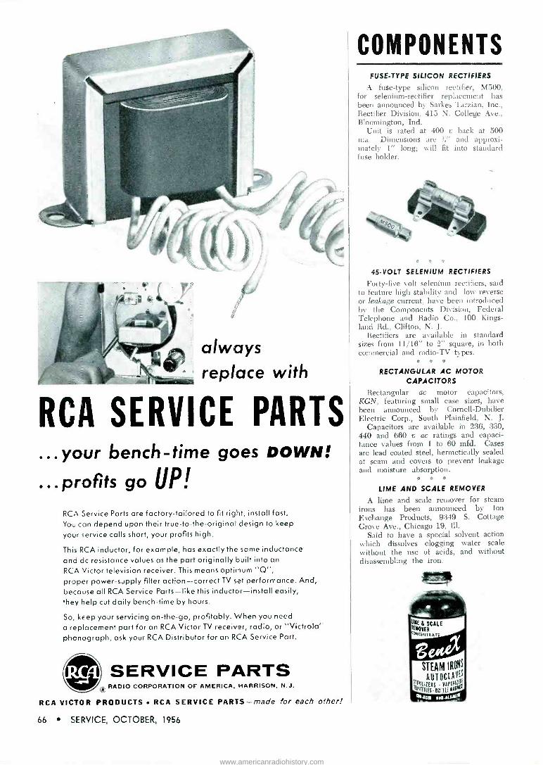
always replace with
RCA SERVICE PARTS ...your bench -time goes DOWN!
...profits go UP! RCA Service Parts are factory -tailored to fit right, install fast. You can depend upon their true -to -the -original design to keep
your service calls short, your profits high.
This RCA inductor, for example, has exactly the same inductance and dc resistance values as the part originally built into an
RCA Victor television receiver. This means optimum "Q", proper power -supply filter action-correct TV set performance. And, because all RCA Service Parts-like this inductor-install easily, they help cut daily bench -time by hours.
So, keep your servicing on -the -go, profitably. When you need
a replacement part for an RCA Victor TV receiver, radio, or "Victrola'u phonograph, ask your RCA Distributor for an RCA Service Part.
eel SERVICE PARTS iris RADIO CORPORATION OF AMERICA, HARRISON, N.J.
RCA VICTOR PRODUCTS RCA SERVICE PARTS-made for each cher!
66 SERVICE, OCTOBER, 1956
COMPONENTS FUSE -TYPE SILICON RECTIFIERS
A fuse -type silicon rectifier, M500, for selenium -rectifier replacement has been announced by Sarkes Tarzian, Inc., Rectifier Division, 415 N. College Ave., Bloomington, Ind.
Unit is rated at 400 e back at 500 ma. Dimensions are ', i" and approxi- mately 1" long; will fit into standard fuse holder.
C O C
45 -VOLT SELENIUM RECTIFIERS
Forty-five volt selenium rectifiers, said to feature high stability and low reverse or leakage current, have been introduced by the Components Division, Federal Telephone and Radio Co., 100 Kings - land Rd., Clifton, N. J.
Rectifiers are available in standard sizes from 11/16" to 2" square, in both commercial and radio -TV types.
RECTANGULAR AC MOTOR CAPACITORS
Rectangular ac motor capacitors, KGN, featuring small case sizes, have been announced by Cornell-Dubilier Electric Corp., South Plainfield, N. J.
Capacitors are available in 236, 330, 440 and 660 u ac ratings and capaci- tance values from 1 to 60 mfd. Cases
are lead coated steel, hermetically sealed at seam and covers to prevent leakage and moisture absorption.
LIME AND SCALE REMOVER
A lime and scale remover for steam irons has been announced by Ion Exchange Products, 9:349 S. Cottage Grove Ave., Chicago 19, Ill.
Said to have a special solvent action which dissolves clogging water scale without the use of acids, and without disassembling the iron.
ENE & SCALE teoVER `''NC[NTN ATE
STEAM IRONS
IEtItIIAEAST OCL AYE is 'AtEITLES BOTTLE low' lent, YOY ALIAlle
www.americanradiohistory.com

ADVERTISERS IN SERVICE
TV Antennas (Continued from page 33) SHE Tv TROUBLE FAST
OCTOBER, 1956
Page
Alliance Manufacturing Co., Inc 5
American Pamcor, Inc 49
Amphenol Electronics Corp 46
Appliance Service Co 42
Argos Products Co. 2
Astron Corp. 9
Avco Manufacturing Corp., Electronics Div. 1
B&K Manufacturing Co. 48
Bussmann Manufacturing Co ... 8
Channel Master Corp. 6, 7
Chemical Electronic Engineering, Ins 60 H. G. Cisin 67
Cornell-Dubilier Electric Corp. Inside Front Cover, 61
Duotone Co., Inc 56
Dynamic Electronics -New York, Inc 68
Electronic Instrument Co., Inc 54
Erie Resistor Corp. 64
Fast Chemical Products Corp 62
Heath Co. Hickok Electrical Instrument Co Hotpoint Co. Hycon Electronics, Inc
58 67 25 47
Jensen Industries, Inc. 54
JFD Manufacturing Co., Inc.......... 17, 18
Kester Solder Co.
Luxo Lamp Corp
58
64
P. R. Mallory and Co., Inc. Inside Back Cover
Merit Coil and Transformer Corp 54
Mosley Electronics, Inc 60
Moss Electronic Distributing Co., Inc..51, 52
Perma-Power Co. Permo, Inc. Philco Corp., Accessory Div Precision Apparatus Co., Inc. Precision Electronics, Inc..........
Pyramid Electric Co.
Quam-Nichols Co.
50 42
37
3
62 4
55
The Radiart Corp... Inside Front Cover, 61 Radio Corporation of America, Tube
Div. Back Cover, 31, 39, 66 RCA Service Co., Inc. Raytheon Manufacturing Co Recoton Corp. Remington Rand Univac, Div. of
Sperry -Rand Corp. John F. Rider, Publisher, Inc Rohn Manufacturing Co.
65 10
50
29 38 44
Howard W. Sams and Co., Inc. 63 Shure Brothers, Inc. 53 Simpson Electric Co. 68 Snyder Manufacturing Co. 35
Sonotone Corp. 57
Technical Appliance Corp 43 Tenna Manufacturing Co. 45 Trio Manufacturing Co. 14 Tung -Sol Electric, Inc. 26, 27
University Loudspeakers, Inc 59
Weston Electrical Instrument Co., Inc.. 56 Winegard Co. 60
the legitimate expectations of his ten- ants. The latter is usually not a dif- ficult job, for the landlords can usu- ally be sold on the idea that a single, well -designed distribution system will provide more reliable television re- ception at a far less cost than reason- ably -priced individual residential in- stallations in the same community. This feature is also a good selling point for landlords in leasing apart- ments. In many cases, a large pro- portion of prospective small-town apartment tenants are those who have lived in some large city where they had become accustomed to a steady diet of good television viewing, and are now interested in obtaining TV reception in the fringe -area provided the cost is not excessive.
If a landlord has been plagued with a number of requests for such a system, he may welcome a contract for its installation.
Technical Problems
In one installation we encountered a problem that merits comment. In this particular case, a secondary branch using shielded twin -lead cable had been installed during a hot summer period in a new air-con- ditioned apartment unit.
When the branch was first installed, it gave perfect performance. However, on the second day, the sig- nal-to-noise ratio appeared some- what impaired and on the third day the signal had practically disap- peared. At first it was thought that the cable had broken or shorted out. The branch cable was checked by open and short circuit tests with an ohmmeter, and the cable checked out all right. After considerable head - scratching, it was decided that the cold air in the apartment had crawled down the air space inside the shield- ing of the cable and had caused pro- gressive moisture to condense out of the warm air in the low portion of the branch run. This length of condensed water, of course, did not cause a dc short circuit or an open circuit, but it caused a severe cable mismatch as well as extremely high rf signal at- tenuation. In this particular case, a satisfactory answer was provided by pulling out the shielded twin -lead and substituting a run of unshielded twin -lead; however, an equally good answer would have been to seal air- tight both ends of the branch cable.
With H. G. Cisin's Copyrighted RAPID "TV TROUBLE SHOOTING
METHOD" Without experience or knowledge, this guaranteed
new method of servicing TV sets, enables you to DIAGNOSE TV troubles as midis, u an expert. NO THEORY-NO MATH-you can locate all faulte in record -breaking time regardless of make or model.
"TV TROUBLE SHOOTING METHOD" 1s the most valuable aid to TV servicing aver written. Bo a TV Trouble Diagnoeticien. Increase your present earnings. Open your own Profitable Business or get a high -paying skilled job.
It's all in this book .
Nothing more to Pay-Nothing else to Buy 85 picture troubles, over 56 raster and 17 sound troubles. By this unique copyrighted method you know EXACTLY WHERE the trouble is: plus step-by- step instructions, including 69 RAPID CHECKS, enabling you to find the faulty part.
13 IMPORTANT PRELIMINARY CHECKS NEED NO INSTRUMENTS! Of the 69 Rapid Checks, OVER 85 ALSO REQUIRE NO INSTRUMENTS! Rapid checks include emergency cheeks for distorted pic- tures, defective tubes Including PIX tube, plus 57 others. ALL EXPLAINED IN SIMPLE LANGUAGE. PERFORMED WITHOUT INSTRUMENTS, MANY CHECKS USE THE PICTURE TUBE AS A GUIDE.
H. G. Clain, the author, is the Inventor of the AO/DC midget radio. He licenses RCA, AT&T, eta He has also trained thousands of technicians now owning their own prosperous TV service organiza- tions or holding highly paid TV positions. His years of experience are embodied to this remarkable new book. Guaranteed. Money Back In 5 Days If Not Satiated!
$1 Postpaid
ABSOLUTELY FREE with oaoh order: H. G. Cisin's newest book "TV & RADIO TUBE SUBSTITUTION GUIDE." Gin» di- rect replacements of set and picture tubas. Most valuable servicing aids ACT NOW- get both books postpaid at cost of only oriel
RUSH COUPON NOW! F
H. G. CISIN, CONSULTING ENGINEER, Amanansett, N. Y. Dept. S-32 Enclosed find $1. Rush both books.
Name
Address
City Zone State
- Model 690
.4%_44a1
VHF -UHF Marker Generator Crystal controlled frequency coverage from 4.25 to 225 me on fundamentals - harmonic output on UHF. Optically magnified screen permits most accurate marker setting. Write for technical details ...
THE HICKOK ELECTRICAL INSTRUMENT CO.
10521 Dupont Ave., Cleveland, Ohio
SERVICE, OCTOBER, 1956 67
www.americanradiohistory.com

Compare the new Simpson Color - scope Model 458 with any oscillo- scope on the market. It is an advanced, seven-inch, high -gain, wide -band scope especially designed for color -TV service. Ideal for black and white, too.
100% RESPONSE at 3.58 me color - burst! DUAL bandwidth-narrow or wide! FLAT FREQUENCY RESPONSE, with- in 1 db to 4.5 mc! RISE TIME less than 0.05 microsecond (wide band) !
FULL RANGE compensated vertical attenuator! Price with shielded input cable, manual.... S22995 Four accessory probes available for extra utility!
See your distributor for details or write-
Ralj R.Sunpx,n 50'° ANNIVERSARY
IU TRF INSTRUKNE BUSINESS
'SIMPSON Electric Company WORLD'S LARGEST MANUFACTURER
OF ELECTRONIC TEST EQUIPMENT
5200 W. Kinzie St., Chicago 44, Illinois Phone: EStebrook 9-1121
In Canada: Bach -Simpson Ltd., London, Ont.
Tube News
SIx REPLACEMENT TUBES for TV and auto radio have been announced by Raytheon: 8BA8A, 8CM7, 12AF6, 12CN5, 17AX4GT and 17DQ6.
The 8BA8A, a heater -cathode medium -mu triode and sharp cutoff pentode of miniature construction with its triode section designed for use as a sync separator and the pen- tode section as a video amplifier, is a 450 -ma heater type.
The 8CM7, also a 450 -ma type, is a heater -cathode type medium -mu dual triode of miniature construction containing two dissimilar triodes in one envelope, and is designed especially for use as a vertical de- flection amplifier.
Horizontal Frequency Damper
The 17AX4GT, also in the 450 -ma heater family, is a heater -cathode type diode designed for use in hori- zontal frequency damper service and is said to be able to withstand high voltage pulses of line frequency be- tween cathode and both heater and plate elements, such as normally encountered in direct -drive circuits.
The fourth TV tube, 17DQ6, is a heater -cathode type beam pentode for use as a horizontal deflection ampli- fier. It is said to have an extremely high perveance for 90° deflection sys- tems. This is also a 450 -ma tube.
12-V Auto Tubes
The 12AF6 and 12CN5 are auto- radio tubes, designed to operate with plate and screen voltages supplied directly from a 12-v storage battery. The 12AF6 is a heater -cathode min- iature pentode for use as an rf or if amp.
The 12CN5 is also a heater -cathode miniature pentode, designed for use as an if amp.
Series -String Chart
A QUICK SELECTION chart for 600 and 450 -ma series -string tubes has been prepared by G. E.
The chart classifies 52 tube types in the 600 -ma series and 24 types in the 450 -ma series according to elements, typical service, heater vol- tages, maximum ratings, and gives average characteristics.
The recently -developed 450 -ma heater types are intended for use in medium -to -small -size series -string TV receivers, including portable models, where the reduced heater wattage eases ventilation design problems in compact cabinets.
Only the CLEAR PICTURE tomes jhrui
with the NEW and AMAZING
1111111 1111111elle_ - - - rmmaif TENNA with the EXCLUSIVE built-in
HI-PASS FILTER T. M. Reg. Pat. Pend.
THE FIRST TRULY ELECTRONIC INDOOR TV ANTENNA TO GIVE CLEAR FILTERED RECEPTION.
List
$18.95 SATIN BRASS, SATIN CHROME. SATIN COPPER FINISHES.
LUW.W'
C.)-'
Distributed through Parts Distributors only.
THE HI-PASS FILTER SCREENS OUT! . . . all elec-
trical disturbances. Field tests prove that this built-in unit rejects all interfere
ences picked up in the antenna circuit ... only a completely filtered signal comes thru. GUARANTEED TO OUT -PERFORM
ANY INDOOR TV ANTENNA - in re- jecting electrical disturbances-OR
YOUR MONEY BACK'
.11
STRONGEST POS- SIBLE'SIGNAL on any TV.
Powerful high gain phasing ele- ments with adjustable 12 position
channel attenuator. Eliminates ori- entation, ghosts, fuzz, picture tear-
ing, and distortion in practically all locations - on color and
black & white TV.
Manufactured By ... DYNAMIC ELECTRONICS -
NEW YORK, INC. Forest Hills, Long Island, New York
68 . SERVICE, OCTOBER, 1956
www.americanradiohistory.com

Etched Cathode
prevents "middle age hum"
incapacitors
.4" Do your capacitors have etched cathodes? If not, chances are they are developing "middle age hum"-may cost you some dissatisfied customers.
All Mallory FP's, and all popular Mallory metal and cardboard tubular electrolytics, have etched cathodes- at no extra cost to you. Ask your Mallory distributor why this is important ... or write directly to us.
P. R. MALLORY 8 CO. Inc.
P. R MALLORY & CO. Inc., INDIANAPOLIS 6, INDIANA
. _ another
MAY service -engineered
product
Capacitors Vibrators Resistors Contrals Switches
Rectifers Power Supplies filters Mercury Bakeries
www.americanradiohistory.com

Show your customers what RCA Silverama Picture Tubes can do :for their ald TV sets
Today, and each succeeding day, too, there is a vast new replacement market opening up for you with RCA SILVERAMA Super -Aluminized Picture Tubes. Many customers are no longer satisfied with dull, dim TV pictures on their present sets-and many are not even waiting until the picture tube is gone
entirely. They want the maximum light output and picture clarity their set is capable of giving right now.
These potential customers have seen the RCA SILVERAMA TV commercials...they have read about the advantages of RCA SILVERAMA Picture Tubes in Life, Saturday Evening Post, and TV Guide...they are pre -sold on the technical advantages of RCA SILVERAMA Picture Tubes...and they want to see it for
themselves.
It's smart business for you to "sell -up" to an RCA SILVERAMA when a replacement picture tube is
needed-and your customer benefits, too, in increased viewing pleasure backed by a reliable RCA product. Next time you're on a replacement call recommend SILVERAMA and add another satisfied customer to your list.
See Your RCA Distributor for Silverama display material and sales helps.
The RCA SILVERAMA line meets virtually every set need
-just 25 types handle over i 10 replacements.
PICTURE TUBES Radio Corporation of America Harrison, N.J.
www.americanradiohistory.com