Technical instructions - Krah Pipes kataloogid...4 Additionallyit is possible to produce pipes with...
28
Technical instructions Krah drainage, water and sewage piping systems
Transcript of Technical instructions - Krah Pipes kataloogid...4 Additionallyit is possible to produce pipes with...

Technicalinstructions
Krah drainage, waterand sewage piping systems

2

32
Table of contents
KRAH Structured pipes 41. Technical parameters 1.1.Specificlightweight 6 1.2.Flexibility 6 1.3.Abrasionresistance 6 1.4.Impactresistance 6 1.5.Hydraulics 7 1.6.UV-resistance 7
2. Profiles 2.1.Profileandringstiffness 8 2.2.ProfiletypesofKRAHpipes 8
3. Designing 3.1.Calculatingofhydraulicparameters 10 3.2.Staticcalculationofpipesforundergroundinstallation 12 3.3.Pipefittings 12 3.4. Branches 12 3.5. Bends 12 3.6.Reductions 13 3.7.Manholes 13
4. Jointing methods for KRAH pipes 4.1.Jointingpipesusingintegratedelectro-fusionfittings 16 4.2.JointingKRAHpipesusinggasket 18
5. Installation of KRAH pipes 5.1. Trench 19 5.1.1Widthofatrench 19 5.1.2Removalofwater 20 5.2.Fillingmaterialandsupport 20 5.3.Backfill 21 5.4.Packing 21 5.5.Leakagetest 21
6. Pipe-in-pipe-method renovation 227. Transportation 228. Storage 229. Quality control 23
DIN 16961-2:2010-03 24
4
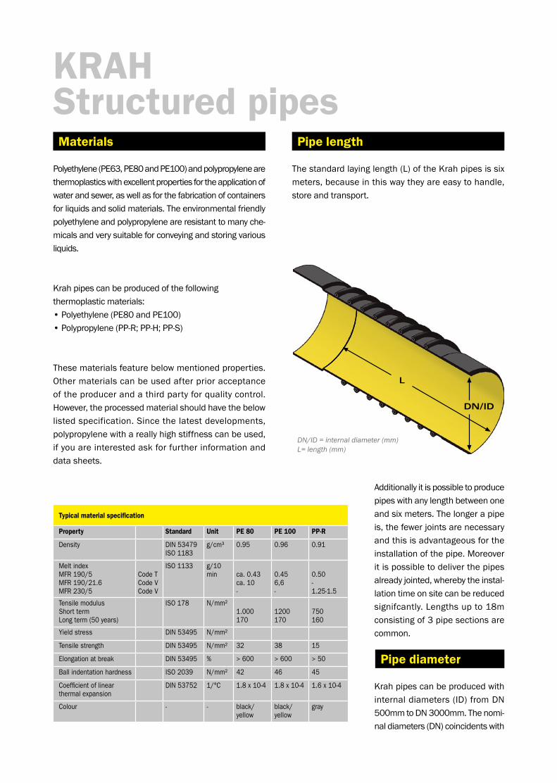
Additionallyitispossibletoproducepipeswithanylengthbetweenoneandsixmeters.Thelongerapipeis,thefewerjointsarenecessaryandthisisadvantageousfortheinstallationofthepipe.Moreoveritispossibletodeliverthepipesalreadyjointed,wherebytheinstal-lationtimeonsitecanbereducedsignifcantly.Lengthsupto18mconsistingof3pipesectionsarecommon.
Krahpipescanbeproducedwithinternaldiameters(ID)fromDN500mmtoDN3000mm.Thenomi-naldiameters(DN)coincidentswith
DN/ID = internal diameter (mm)L= length (mm)
Materials
KRAH Structured pipes
Polyethylene(PE63,PE80andPE100)andpolypropylenearethermoplasticswithexcellentpropertiesfortheapplicationofwaterandsewer,aswellasforthefabricationofcontainersforliquidsandsolidmaterials.Theenvironmentalfriendlypolyethyleneandpolypropyleneareresistanttomanyche-micalsandverysuitableforconveyingandstoringvariousliquids.
Krahpipescanbeproducedofthefollowing thermoplasticmaterials:•Polyethylene(PE80andPE100)•Polypropylene(PP-R;PP-H;PP-S)
Thesematerialsfeaturebelowmentionedproperties.Othermaterialscanbeusedafterprioracceptanceoftheproducerandathirdpartyforqualitycontrol.However,theprocessedmaterialshouldhavethebelowlistedspecification.Sincethelatestdevelopments,polypropylenewithareallyhighstiffnesscanbeused,ifyouareinterestedaskforfurtherinformationanddata sheets.
Pipe diameter
Pipe length
Typical material specification
Property Standard Unit PE 80 PE 100 PP-R
Density DIN 53479ISO 1183
g/cm³ 0.95 0.96 0.91
Melt index MFR 190/5MFR 190/21.6MFR 230/5
Code TCode VCode V
ISO 1133 g/10 min
ca. 0.43ca. 10-
0.456,6-
0.50-1.25-1.5
Tensile modulusShort termLong term (50 years)
ISO 178 N/mm² 1.000170
1200170
750160
Yield stress DIN 53495 N/mm²
Tensile strength DIN 53495 N/mm² 32 38 15
Elongation at break DIN 53495 % > 600 > 600 > 50
Ball indentation hardness ISO 2039 N/mm² 42 46 45
Coefficient of linear thermal expansion
DIN 53752 1/°C 1.8 x 10⁻⁴ 1.8 x 10⁻⁴ 1.6 x 10⁻⁴
Colour - - black/ yellow
black/ yellow
gray
Thestandardlayinglength(L)oftheKrahpipesissixmeters,becauseinthiswaytheyareeasytohandle,storeandtransport.
54
profiledpipe,theweightcanbereducedupto65%com-paredtoasolidwallpipewiththesameringstiffness.Krahpipesofferthebestsecurityanddurability.Thewallthicknessesofourpipescanbeadaptedinsmallstepstotherespectiveload.
TheKrahpipesystemcanwithstandlowworkingpres-sureupto3bar,dependingonthethicknessofthewaterwaywall(s1).EquivalenttoDIN8074thehoopstressformulacanbeusedtocalculatethes1astheminimumwallthickness.
Ifrequestedallpipescanbedeliveredeitherwithabright,inspectionfriendlyoranelectroconductiveinnersurfacemadebytheco-extrusionprocess.
Theco-extrusionensuresan inspection friendly,brightinnersurfaceandatthesametimealongtermUV-resistantoutersurface(forexampleforthestorageofpipesoutsideforalongtime).
TheKrahpipesystemisdesignedtomeettherequi-rementsofpresentapplicableinternationalnormsandstandards.KrahAGismemberofthemajorstan-dardizationcommitteestoguaranteethatthepipesarecorrespondingtothestandards,butalsothatthestandardsarecorrespondingtothepipes.
Thequalityofthepipeishighlydependingonthequalityofthewaterwaywall,thereforeallKrahpipesareproducedwithaminimumwaterwaywallof4mm.
Thegreatadvantageofthisdevelopmentisthataprofi-ledpipehasaverylowweight,butatthesametimecanbeusedforhighloadapplications.Alotlessmaterialisneededtoproduceapipewiththesamestaticalproperti-esthanasolidwallpipe,whichmeanssignificantsavingsinmaterialcosts.
Thesupportablestaticloadisdeterminedforeverypro-filegeometrybythefactorselasticmodulus(N/mm2)oftherespectivematerialandthemomentofinertiaoftheprofilegeometry(mm4/mm)referringtothepipediameter.Theresultiscalledringstiffness.Byusinga
theinternaldiameter(ID)ofthepipe,becauseincaseofanychangeinthedesignofthepipe,thewallthicknesscanbeincreasedorreducedwhiletheinternaldiameterremai-nsthesame.Thisensuresthatthedesignatedhydrauliccapacityfortheinstallationismaintained.
Bothprofiledandsolidwallpipeswithwallthicknessesupto300mmcanbeproduced.
Wall thicknesses
Minimum wall thickness in accordance with the standard EN 13476, Figure 5.
Normal pipe dimen-sions DN/ID (mm) s1 PE pipe (mm) s1 PP pipe (mm)
300 2.0 2.0
400 2.5 2.5
500 2.5 3.0
600 3.3 3.5
800 4.5 4.5
1000 5.0 5.0
> 1200 5.0 5.0
Profiled pipe wall
Internal pressure
Co-extrusion
Norms and standards

6
Thehighimpactresistance,evenatlowtemperatures,ensuresarobustpipe,resistantagainstimpactsduringtransport,installationonthesiteandduringthewholeservicelifeconditions.
anybreaksorcracks,sothattheactivityofthepipelineisnotdrasticallyaffected.Assoonastheoverloadandearthmovementends,thepipewillgobacktoitsinitialconditionandposition.
Anotheradvantageisthehighflexibility.Eveninareaswhicharehighlyaffectedby11earthquakes,ourpipesarehardlydamagedincomparisontopipesmadeofothermaterials.DespitetheflexibilityoftheKrahpipestheyhaveagreatcapacitytocarryloads,sothattheyarealsosuitableforroadconstruction.
Polyethyleneandpolypropylenepipesareamongthemostabrasionproofpipes.Thishasbeentestedintheso-calledDarmstadtprocedureandtheresultsareshowninthebelowdiagramandconfirmthequalityofpolyethylenepipes.Testshavebeenperformedatthe”SüddeutscheKunststoffzentrum”foritsapproval.
1. Technicalparameters
TheKrahpipeshaveaverylowweightandthereforeareeasytohandleduringinstallation,whichmakestheusageofacraneonsiteinmostofthecasesunnecessary.
1.1. Specific light weight
Material characteristic values
Specific weight in kg/dm3
Concrete pipe coated
Concrete pipe
PP or PE pipe
Clay pipe
GFK pipe
Abrasion in mm
Cycles
PVC pipe
PE PVC GFK Clay Concrete Ductile Steel
PipesmadeofPolyethyleneandPolypropylenehaveconsi-derableadvantagestootherpipematerialslikeconcrete,steel,ductileetc.DuetotheirmaterialtheKrahpipespossesoverahighelongationatbreak.Thissignifies,thatthepipecansupportevenloadsordeformations,thatwerenotincludedintheactualcalculationanddesignofthepipe,likeforexamplesearthquakes.TheKrahpipesdeformconformwiththemovementoftheearthwithout
By using profiled pipes we can safe weight up to 65% compared to equivalent solid wall pipes with the same statical capacity.
1.2. Flexibility
1.3. Abrasion resistance
Abrasion curve of various pipe materials according to the Darmstadt procedure.
1.4. Impact resistance
76
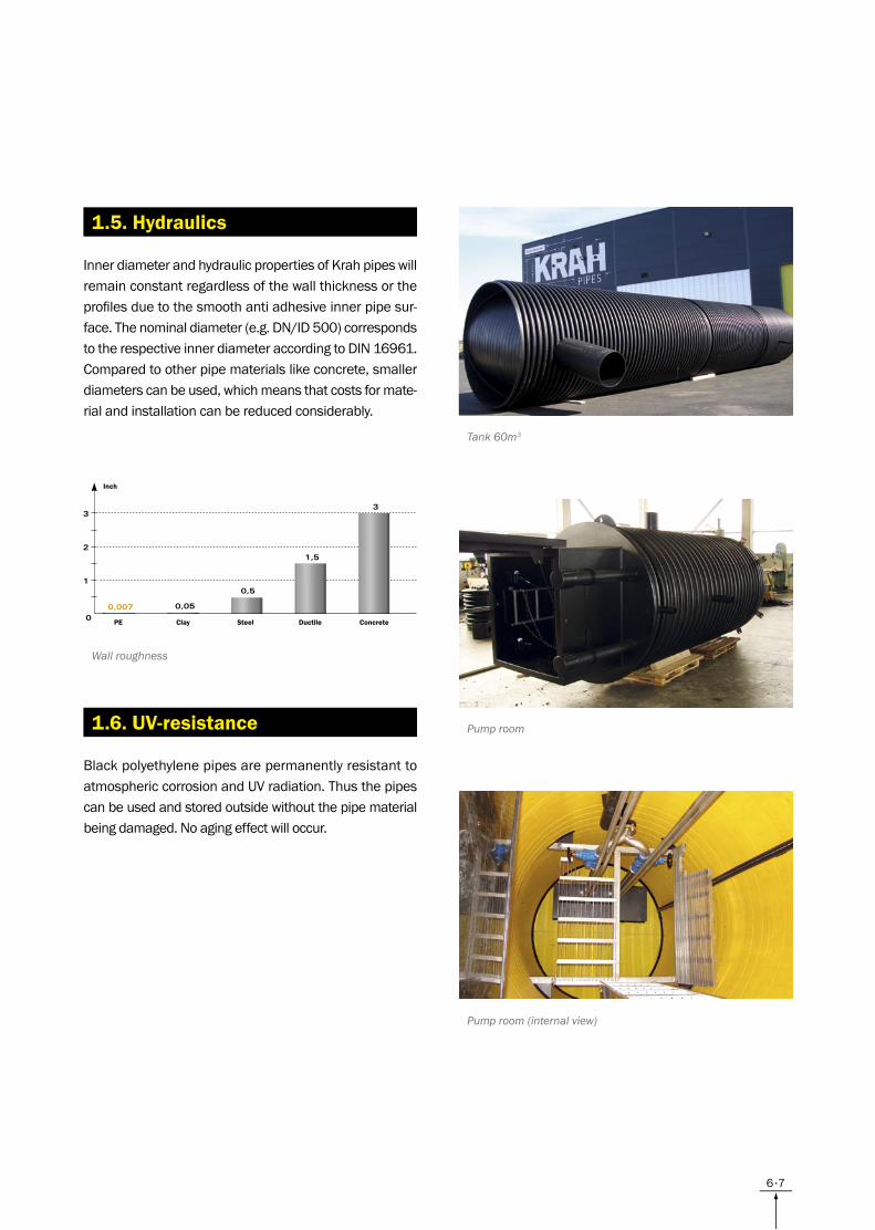
1.6. UV-resistance
1.5. Hydraulics
Wall roughness
InnerdiameterandhydraulicpropertiesofKrahpipeswillremainconstantregardlessofthewallthicknessortheprofilesduetothesmoothantiadhesiveinnerpipesur-face.Thenominaldiameter(e.g.DN/ID500)correspondstotherespectiveinnerdiameteraccordingtoDIN16961.Comparedtootherpipematerialslikeconcrete,smallerdiameterscanbeused,whichmeansthatcostsformate-rialandinstallationcanbereducedconsiderably.
BlackpolyethylenepipesarepermanentlyresistanttoatmosphericcorrosionandUVradiation.Thusthepipescanbeusedandstoredoutsidewithoutthepipematerialbeingdamaged.Noagingeffectwilloccur.
Tank 60m3
Pump room
Pump room (internal view)
PE Clay ConcreteSteel
Inch
Ductile

8
Profile type: SQ
Thisprofilepipehasasmoothinsideandoutsideinclud-inginternalprofileswithoneormorelayers.Thisprofilehasaveryhighlong-termstiffnessthereforeitisverysuitableforextremelyhighloadsandbigdiameters.
Profile type: VW
ThetypeVWisahomogeneoussolidpipewithsmoothinsideandoutsidesurface.Thesepipescanbeusedforinternalworkingpressure.Theminimumwallthicknessmeasures5mm,themaximumthicknessis80mm.
Profile type: ST
PipeswiththeprofiletypeSTarespeciallymadeforver-ticaltanks,wheredifferentwallthicknessesinonepipearerequiredtosavematerial.ThecalculationmethodisaccordingtoDVS2205.
2. Profiles
Theringstiffnesswillbedeterminedforeachprofile,baseduponthelong-termelasticitymoduleofthePolyethylene(Young’smodule),themomentofinertiaoftheprofileandthediameterofpipe.Usingstructuralpipewallssignificantlyreducestheweightofthepipescom-paredtopipesusedinregularconstructionwithequalringstiffness.ThestructuralwallofKrahpipesmakesitpossibletousethesepipesforlargestaticloads.
Profile type: PR
ThemainpropertiesoftheprofileseriePRisthesmoothinsideandtheprofiledoutside.Thelowweightandthehighstiffnessaresignificant.
Thefieldsofapplicationforthiskindofprofilesarepipelinesystemslikeforexamplesewer,drain,stormdrainandventilation.
Profile type: OP
ThisprofilehasasmoothinsidesurfaceandtheoutsidesurfaceisprofiledwithanOlympic-rings-alikepattern.Themaincharacteristicsofthisprofilearealsoitslowweightandveryhighstiffness.
2.1. Profile and ring stiffness
2.2. Profile types of KRAH pipes
Profile no
Ix [mm4/mm]
e [mm] se [mm]
PR 317 - 47 548 6.02 - 36.38 15.61 - 82.94
OP 14 942 - 194 000 32.98 - 75 56.39 - 132.44
SQ1 7 700 - 27 000 22.74 - 37.52 45.35 - 68.68
SQ2 34 400 - 107 900 41.32 - 65.07 74.48 - 108.99
SQ3 92 000 - 300 000 60.04 - 95.99 103.35 - 153.18
List of typical profileslx = moment of inertia, e = distance of inertia,se = equivalent solid wall thickness
Technical data of stepped pipes
Stepped pipes minimum maximum
Nominal width (Di) 300 (mm) 4000 (mm)
Number of steps (n) two six
Length of step (L) 200 (mm) length of a pipe
Wall thickness of step (s) 5 (mm) 300 (mm) for PE150 (mm) for PP
Step distance 5 (mm)
Profile type
Cross-section View
PR
OP

98
Sketch of a stepped vertical storage tankS1 = wall thickness of the step iL1 = length of the step i
ID Profile SN h OD a
500
PR21 2 27 554 120
PR34 4 39 578 120
PR34 6 39 578 120
PR34 8 39 578 100
600
PR21 2 29 658 120
PR34 4 39 678 120
PR34 6 41 682 120
PR42 8 46 692 100
800
PR34 2 39 878 120
PR42 4 48 896 120
PR54 6 60 920 120
PR54 8 60 920 120
1000
PR42 2 46 1092 100
PR54 4 60 1120 120
PR65 6 71 1142 140
PR65 8 73 1146 140
ID Profiil SN h OD a
1200
PR54 2 60 1320 120
PR65 4 71 1342 120
PR75 6 83 1366 140
PR75 8 85 1370 140
1400
PR65 2 71 1542 140
PR75 4 83 1566 140
PR75 6 87 1574 140
PR75 8 91 1582 140
1500
PR65 2 71 1642 120
PR75 4 85 1670 140
PR75 6 89 1678 120
PR75 8 95 1690 140
1600
PR65 2 73 1746 140
PR75 4 87 1774 140
PR75 6 93 1786 140
PR75 8 97 1794 140
1800
PR75 2 83 1966 140
PR75 4 91 1982 140
OP65 6 122 2044 120
OP65 8 127 2054 120
2000
PR75 2 85 2170 120
OP65 4 117 2234 120
OP65 6 127 2254 120
OP65 8 132 2264 140
2200
PR75 2 89 2378 120
OP65 4 127 2454 100
OP65 6 135 2470 100
OP65 8 142 2484 120
2400
PR75 2 93 2586 140
OP65 4 132 2664 120
OP65 6 141 2682 120
OP65 8 151 2702 100
3000
OP65 2 131 3262 100
OP65 4 148 3296 120
OP65 6 169 3338 100
SQ354-299.51 8 171 3342 61
Figure 1.1 Profile types of KRAH pipes
10
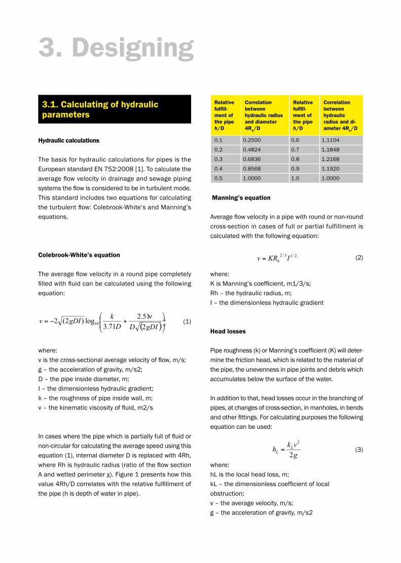
Relative fulfill-ment of the pipe h/D
Correlation between hydraulic radius and diameter 4R
h/D
Relative fulfill-ment of the pipe h/D
Correlation between hydraulic radius and di-ameter 4R
h/D
0.1 0.2500 0.6 1.1104
0.2 0.4824 0.7 1.1848
0.3 0.6836 0.8 1.2168
0.4 0.8568 0.9 1.1920
0.5 1.0000 1.0 1.0000
3. Designing
Hydraulic calculations
ThebasisforhydrauliccalculationsforpipesistheEuropeanstandardEN752:2008[1].Tocalculatetheaverageflowvelocityindrainageandsewagepipingsystemstheflowisconsideredtobeinturbulentmode.Thisstandardincludestwoequationsforcalculatingtheturbulentflow:Colebrook-White’sandManning’sequations.
Colebrook-White’s equation
Theaverageflowvelocityinaroundpipecompletelyfilledwithfluidcanbecalculatedusingthefollowingequation:
where:visthecross-sectionalaveragevelocityofflow,m/s;g–theaccelerationofgravity,m/s2;D–thepipeinsidediameter,m;I–thedimensionlesshydraulicgradient;k–theroughnessofpipeinsidewall,m;v–thekinematicviscosityoffluid,m2/s
Incaseswherethepipewhichispartiallyfulloffluidornon-circularforcalculatingtheaveragespeedusingthisequation(1),internaldiameterDisreplacedwith4Rh,whereRhishydraulicradius(ratiooftheflowsectionAandwettedperimeterχ).Figure1presentshowthisvalue4Rh/Dcorrelateswiththerelativefulfillmentofthepipe(hisdepthofwaterinpipe).
3.1. Calculating of hydraulic parameters
Manning’s equation
Averageflowvelocityinapipewithroundornon-roundcross-sectionincasesoffullorpartialfulfillmentiscalculatedwiththefollowingequation:
where:KisManning’scoefficient,m1/3/s;Rh–thehydraulicradius,m;I–thedimensionlesshydraulicgradient
Head losses
Piperoughness(k)orManning’scoefficient(K)willdeter-minethefrictionhead,whichisrelatedtothematerialofthepipe,theunevennessinpipejointsanddebriswhichaccumulatesbelowthesurfaceofthewater.
Inadditiontothat,headlossesoccurinthebranchingofpipes,atchangesofcross-section,inmanholes,inbendsandotherfittings.Forcalculatingpurposesthefollowingequationcanbeused:
where:hListhelocalheadloss,m;kL–thedimensionlesscoefficientoflocalobstruction;v–theaveragevelocity,m/s;g–theaccelerationofgravity,m/s2
(2)
(1)
(3)

1110
Total head loss
Tocalculatethetotalheadlossthefollowingmethodsarerecommended[1]:
• Toaddlocalheadlossestofrictionheadlossescausedbyflowinpipes;
• Assuminghigherhydraulicroughnesswhile calculatingthefrictionheadlosses,thelocal headlossesareconsideredtoaccruetothe totalheadloss.
Whenusingrecommendedhydraulicroughnessincalculatingthepipesitisnecessarytodeterminewhe-thertheimpactoflocalheadlosseshasbeenaddedtothevalueoftheroughness.Inpractice,thekvaluesfortheroughnessofthepipeinsidewallarenormallybetween0.03mmand3.0mmandManning’scoef-ficientKisbetween70and90m1/3s-1.
Anapproximatecomparisonbetweenestimationsofcomputationalvelocitiesbaseduponequations(1)and(2)canbeperformedusingthefollowingequation:
where: KisManning’scoefficient,m1/3/s; g–theaccelerationofgravity,m/s2; D–thepipeinsidediameter,m; k–thepipeinsidewallroughness,m
Thechoiceofpipediameterisdependentonthepipegradient,thevolumetricflowrateandtheaverageflowvelocity.Thisisaidedbyanomogram,whichisshowninFigure1.ThisnomogramwascreatedusingColebrook-White’sequation(1)ontheconditionthatthepipeisentirelyfull,theviscosityofwaterv=1.0310-6m2/sandthepipe’sinsidewallroughnessk=0.00710-3m.Incaseswherethereisapartiallyfullpipe,inequation(1)diameterDshallbereplacedwith4Rh.
Figure 1. Nomogram
(4)
Gradient
Volu
met
ric fl
ow ra
te
12
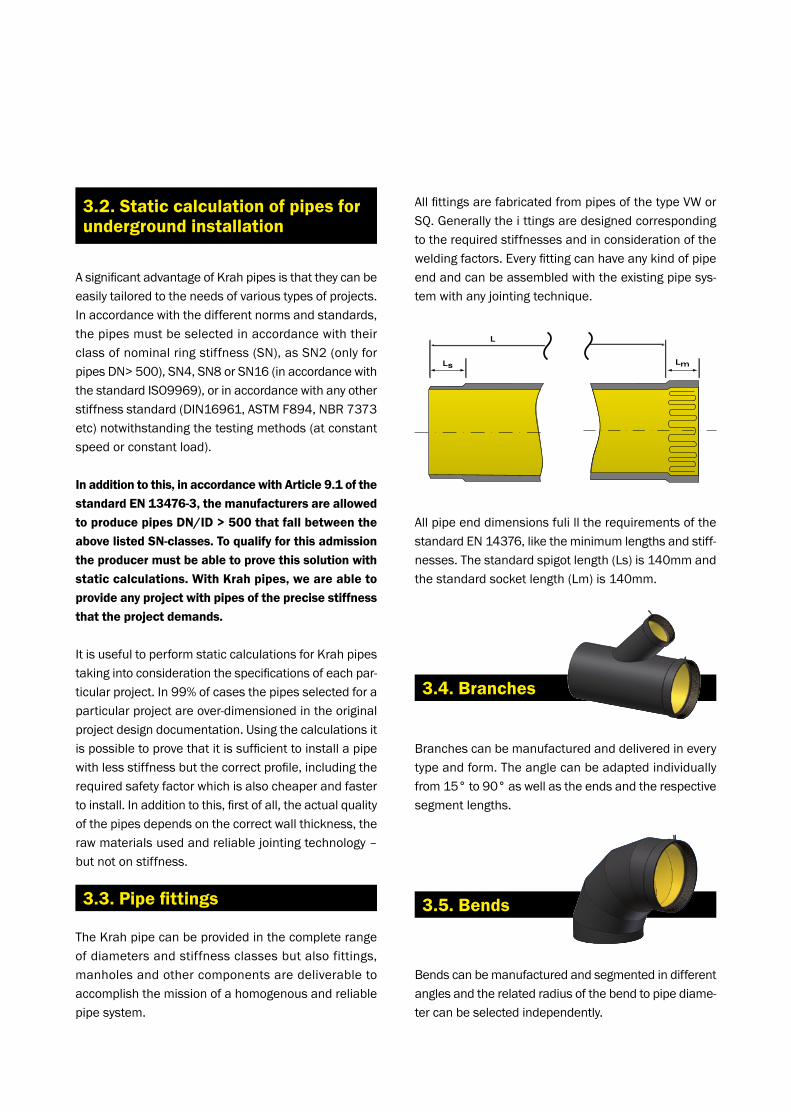
AllfittingsarefabricatedfrompipesofthetypeVWorSQ.Generallytheittingsaredesignedcorrespondingtotherequiredstiffnessesandinconsiderationoftheweldingfactors.Everyfittingcanhaveanykindofpipeendandcanbeassembledwiththeexistingpipesys-temwithanyjointingtechnique.
AllpipeenddimensionsfulilltherequirementsofthestandardEN14376,liketheminimumlengthsandstiff-nesses.Thestandardspigotlength(Ls)is140mmandthestandardsocketlength(Lm)is140mm.
AsignificantadvantageofKrahpipesisthattheycanbeeasilytailoredtotheneedsofvarioustypesofprojects.Inaccordancewiththedifferentnormsandstandards,thepipesmustbeselectedinaccordancewiththeirclassofnominalringstiffness(SN),asSN2(onlyforpipesDN>500),SN4,SN8orSN16(inaccordancewiththestandardISO9969),orinaccordancewithanyotherstiffnessstandard(DIN16961,ASTMF894,NBR7373etc)notwithstandingthetestingmethods(atconstantspeedorconstantload).
In addition to this, in accordance with Article 9.1 of the standard EN 13476-3, the manufacturers are allowed to produce pipes DN/ID > 500 that fall between the above listed SN-classes. To qualify for this admission the producer must be able to prove this solution with static calculations. With Krah pipes, we are able to provide any project with pipes of the precise stiffness that the project demands.
ItisusefultoperformstaticcalculationsforKrahpipestakingintoconsiderationthespecificationsofeachpar-ticularproject.In99%ofcasesthepipesselectedforaparticularprojectareover-dimensionedintheoriginalprojectdesigndocumentation.Usingthecalculationsitispossibletoprovethatitissufficienttoinstallapipewithlessstiffnessbutthecorrectprofile,includingtherequiredsafetyfactorwhichisalsocheaperandfastertoinstall.Inadditiontothis,firstofall,theactualqualityofthepipesdependsonthecorrectwallthickness,therawmaterialsusedandreliablejointingtechnology–butnotonstiffness.
3.2. Static calculation of pipes for underground installation
3.3. Pipe fittings
TheKrahpipecanbeprovidedinthecompleterangeofdiametersandstiffnessclassesbutalsofittings,manholesandothercomponentsaredeliverabletoaccomplishthemissionofahomogenousandreliablepipe system.
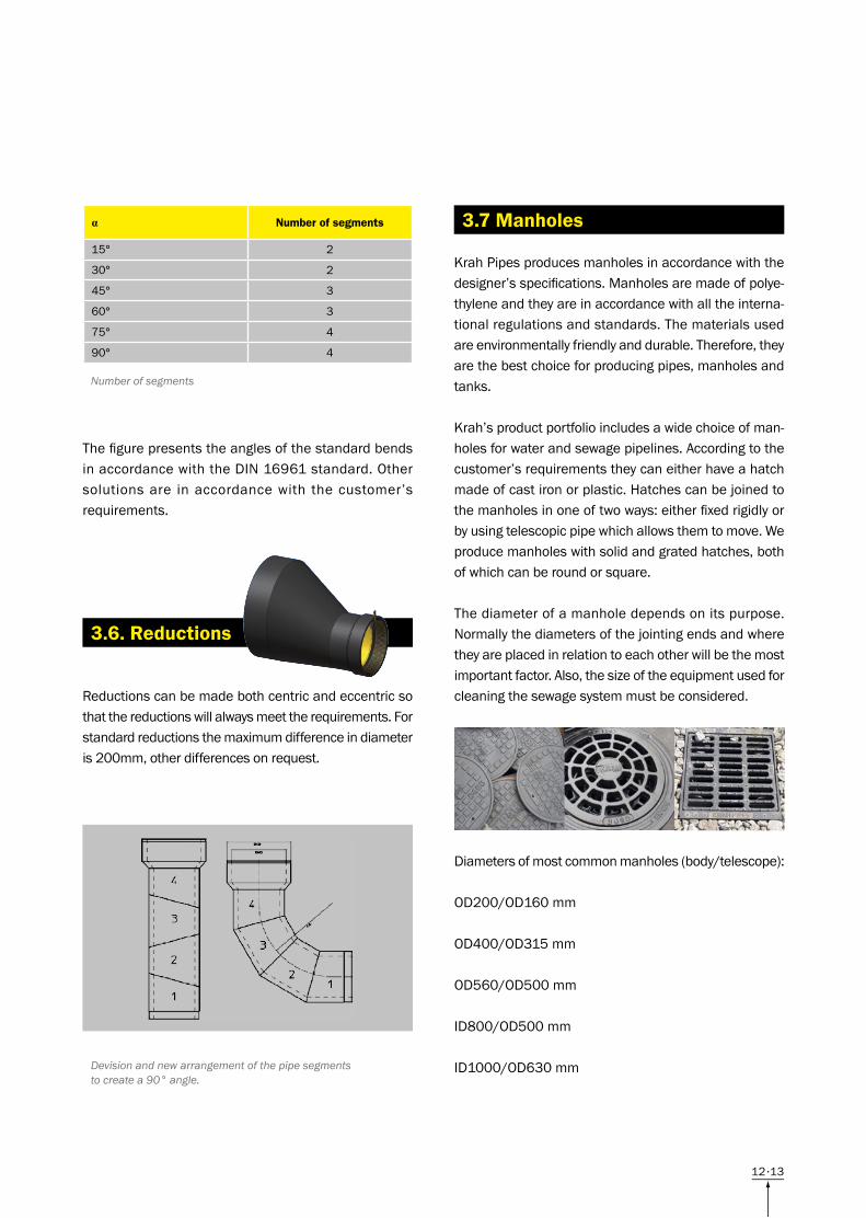
Branchescanbemanufacturedanddeliveredineverytypeandform.Theanglecanbeadaptedindividuallyfrom15°to90°aswellastheendsandtherespectivesegmentlengths.
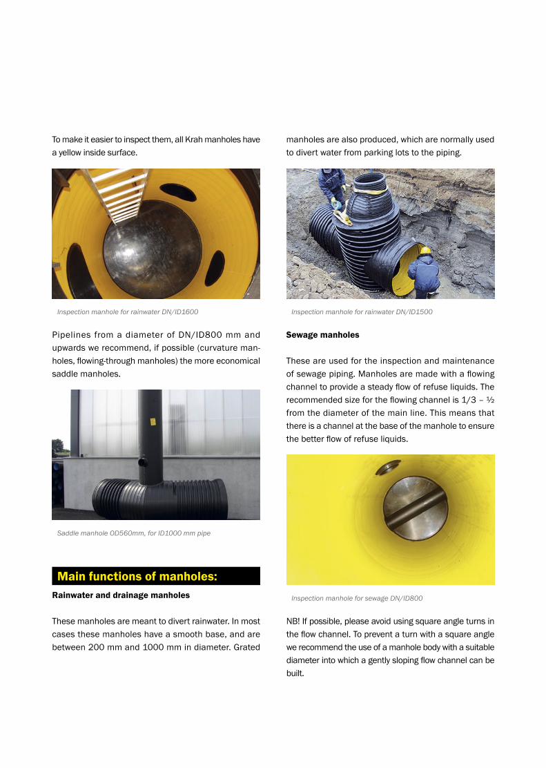
Bendscanbemanufacturedandsegmentedindifferentanglesandtherelatedradiusofthebendtopipediame-tercanbeselectedindependently.
3.4. Branches
3.5. Bends
1312
ThefigurepresentstheanglesofthestandardbendsinaccordancewiththeDIN16961standard.Othersolutionsare inaccordancewith thecustomer’srequirements.
Reductionscanbemadebothcentricandeccentricsothatthereductionswillalwaysmeettherequirements.Forstandardreductionsthemaximumdifferenceindiameteris200mm,otherdifferencesonrequest.
3.6. Reductions
α Number of segments
15° 2
30° 2
45° 3
60° 3
75° 4
90° 4
Number of segments
Devision and new arrangement of the pipe segments to create a 90° angle.
KrahPipesproducesmanholesinaccordancewiththedesigner’sspecifications.Manholesaremadeofpolye-thyleneandtheyareinaccordancewithalltheinterna-tionalregulationsandstandards.Thematerialsusedareenvironmentallyfriendlyanddurable.Therefore,theyarethebestchoiceforproducingpipes,manholesandtanks.
Krah’sproductportfolioincludesawidechoiceofman-holesforwaterandsewagepipelines.Accordingtothecustomer’srequirementstheycaneitherhaveahatchmadeofcastironorplastic.Hatchescanbejoinedtothemanholesinoneoftwoways:eitherfixedrigidlyorbyusingtelescopicpipewhichallowsthemtomove.Weproducemanholeswithsolidandgratedhatches,bothofwhichcanberoundorsquare.
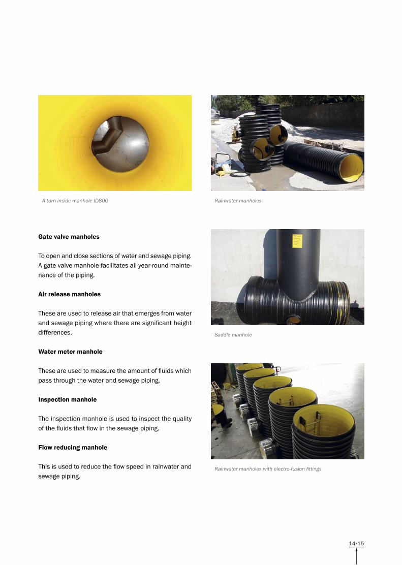
Thediameterofamanholedependsonitspurpose.Normallythediametersofthejointingendsandwheretheyareplacedinrelationtoeachotherwillbethemostimportantfactor.Also,thesizeoftheequipmentusedforcleaningthesewagesystemmustbeconsidered.
Diametersofmostcommonmanholes(body/telescope): OD200/OD160mm
OD400/OD315mm
OD560/OD500mm
ID800/OD500mm
ID1000/OD630mm
3.7 Manholes
14
Tomakeiteasiertoinspectthem,allKrahmanholeshaveayellowinsidesurface.
Pipelines fromadiameterofDN/ID800mmandupwardswerecommend,ifpossible(curvatureman-holes,flowing-throughmanholes)themoreeconomicalsaddlemanholes.
Rainwater and drainage manholes
Thesemanholesaremeanttodivertrainwater.Inmostcasesthesemanholeshaveasmoothbase,andarebetween200mmand1000mmindiameter.Grated
manholesarealsoproduced,whicharenormallyusedtodivertwaterfromparkinglotstothepiping.
Sewage manholes
Theseareusedfortheinspectionandmaintenanceofsewagepiping.Manholesaremadewithaflowingchanneltoprovideasteadyflowofrefuseliquids.Therecommendedsizefortheflowingchannelis1/3–½fromthediameterofthemainline.Thismeansthatthereisachannelatthebaseofthemanholetoensurethebetterflowofrefuseliquids.
NB!Ifpossible,pleaseavoidusingsquareangleturnsintheflowchannel.Topreventaturnwithasquareanglewerecommendtheuseofamanholebodywithasuitablediameterintowhichagentlyslopingflowchannelcanbebuilt.
Main functions of manholes:
Inspection manhole for rainwater DN/ID1600
Saddle manhole OD560mm, for ID1000 mm pipe
Inspection manhole for rainwater DN/ID1500
Inspection manhole for sewage DN/ID800
1514
Gate valve manholes
Toopenandclosesectionsofwaterandsewagepiping.Agatevalvemanholefacilitatesall-year-roundmainte-nanceofthepiping.
Air release manholes
Theseareusedtoreleaseairthatemergesfromwaterandsewagepipingwheretherearesignificantheightdifferences.
Water meter manhole
Theseareusedtomeasuretheamountoffluidswhichpassthroughthewaterandsewagepiping.
Inspection manhole
Theinspectionmanholeisusedtoinspectthequalityofthefluidsthatflowinthesewagepiping.
Flow reducing manhole
Thisisusedtoreducetheflowspeedinrainwaterandsewage piping.
A turn inside manhole ID800 Rainwater manholes
Saddle manhole
Rainwater manholes with electro-fusion fittings
16
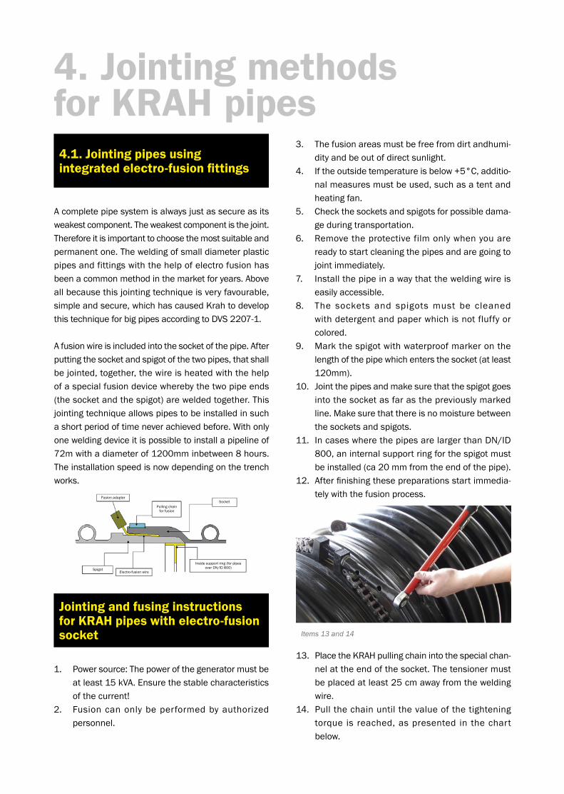
FusionadapterSocket
SpigotElectro-fusionwire
Insidesupportring(forpipesoverDN/ID800)
Pullingchainforfusion
3. Thefusionareasmustbefreefromdirtandhumi-dityandbeoutofdirectsunlight.
4. Iftheoutsidetemperatureisbelow+5°C,additio-nalmeasuresmustbeused,suchasatentandheatingfan.
5. Checkthesocketsandspigotsforpossibledama-geduringtransportation.
6. Removetheprotectivefilmonlywhenyouarereadytostartcleaningthepipesandaregoingtojointimmediately.
7. Installthepipeinawaythattheweldingwireiseasilyaccessible.
8. The sockets and spigotsmust be cleanedwithdetergentandpaperwhichisnotfluffyorcolored.
9. Markthespigotwithwaterproofmarkeronthelengthofthepipewhichentersthesocket(atleast120mm).
10. Jointthepipesandmakesurethatthespigotgoesintothesocketasfarasthepreviouslymarkedline.Makesurethatthereisnomoisturebetweenthesocketsandspigots.
11. IncaseswherethepipesarelargerthanDN/ID800,aninternalsupportringforthespigotmustbeinstalled(ca20mmfromtheendofthepipe).
12. Afterfinishingthesepreparationsstartimmedia-telywiththefusionprocess.
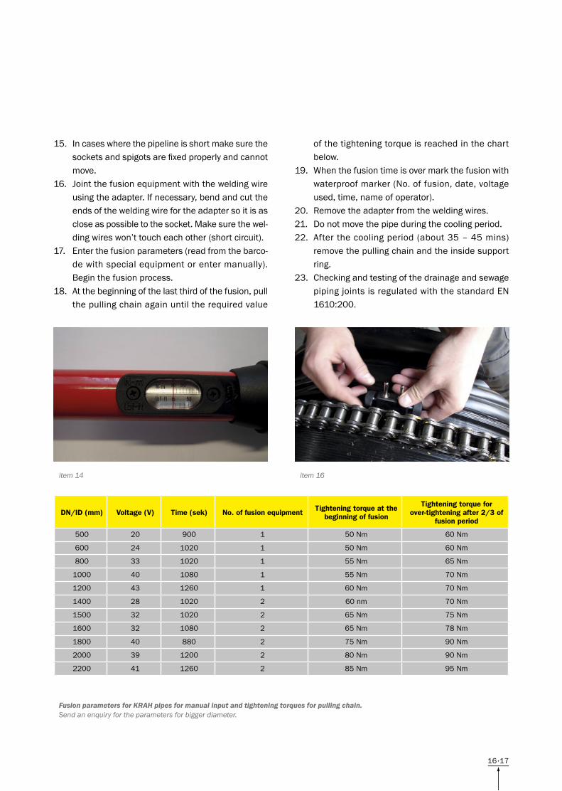
13. PlacetheKRAHpullingchainintothespecialchan-nelattheendofthesocket.Thetensionermustbeplacedatleast25cmawayfromtheweldingwire.
14. Pullthechainuntilthevalueofthetighteningtorque isreached,aspresented inthechartbelow.
Acompletepipesystemisalwaysjustassecureasitsweakestcomponent.Theweakestcomponentisthejoint.Thereforeitisimportanttochoosethemostsuitableandpermanentone.Theweldingofsmalldiameterplasticpipesandfittingswiththehelpofelectrofusionhasbeenacommonmethodinthemarketforyears.Aboveallbecausethisjointingtechniqueisveryfavourable,simpleandsecure,whichhascausedKrahtodevelopthistechniqueforbigpipesaccordingtoDVS2207-1.
Afusionwireisincludedintothesocketofthepipe.Afterputtingthesocketandspigotofthetwopipes,thatshallbejointed,together,thewireisheatedwiththehelpofaspecialfusiondevicewherebythetwopipeends(thesocketandthespigot)areweldedtogether.Thisjointingtechniqueallowspipestobeinstalledinsuchashortperiodoftimeneverachievedbefore.Withonlyoneweldingdeviceitispossibletoinstallapipelineof72mwithadiameterof1200mminbetween8hours.Theinstallationspeedisnowdependingonthetrenchworks.
4. Jointing methodsfor KRAH pipes4.1. Jointing pipes usingintegrated electro-fusion fittings
Items 13 and 14
Jointing and fusing instructions for KRAH pipes with electro-fusion socket
1. Powersource:Thepowerofthegeneratormustbeatleast15kVA.Ensurethestablecharacteristicsofthecurrent!
2. Fusioncanonlybeperformedbyauthorizedpersonnel.
1716
15. Incaseswherethepipelineisshortmakesurethesocketsandspigotsarefixedproperlyandcannotmove.
16. Jointthefusionequipmentwiththeweldingwireusingtheadapter.Ifnecessary,bendandcuttheendsoftheweldingwirefortheadaptersoitisascloseaspossibletothesocket.Makesurethewel-dingwireswon’ttoucheachother(shortcircuit).
17. Enterthefusionparameters(readfromthebarco-dewithspecialequipmentorentermanually).Beginthefusionprocess.
18. Atthebeginningofthelastthirdofthefusion,pullthepullingchainagainuntiltherequiredvalue
ofthetighteningtorqueisreachedinthechartbelow.
19. Whenthefusiontimeisovermarkthefusionwithwaterproofmarker(No.offusion,date,voltageused,time,nameofoperator).
20. Removetheadapterfromtheweldingwires.21. Donotmovethepipeduringthecoolingperiod.22. Afterthecoolingperiod(about35–45mins)
removethepullingchainandtheinsidesupportring.
23. CheckingandtestingofthedrainageandsewagepipingjointsisregulatedwiththestandardEN1610:200.
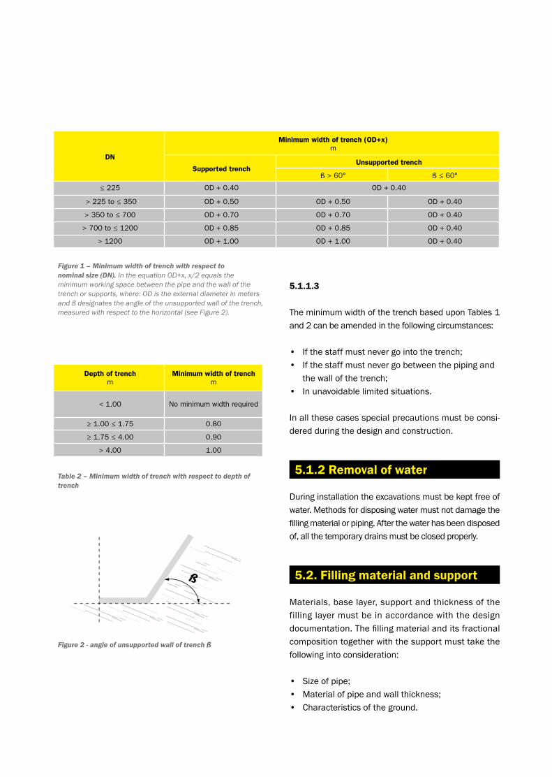
item 14 item 16
DN/ID (mm) Voltage (V) Time (sek) No. of fusion equipment Tightening torque at the beginning of fusion
Tightening torque forover-tightening after 2/3 of
fusion period
500 20 900 1 50 Nm 60 Nm
600 24 1020 1 50 Nm 60 Nm
800 33 1020 1 55 Nm 65 Nm
1000 40 1080 1 55 Nm 70 Nm
1200 43 1260 1 60 Nm 70 Nm
1400 28 1020 2 60 nm 70 Nm
1500 32 1020 2 65 Nm 75 Nm
1600 32 1080 2 65 Nm 78 Nm
1800 40 880 2 75 Nm 90 Nm
2000 39 1200 2 80 Nm 90 Nm
2200 41 1260 2 85 Nm 95 Nm
Fusion parameters for KRAH pipes for manual input and tightening torques for pulling chain.Send an enquiry for the parameters for bigger diameter.

18
• Twogasketsperjoint
• Installthegasketsasshowninthefigure
• Tofacilitatetheinstallation,itwouldbegoodifthegroundaroundoneofthepipestobejointedcouldbepartiallybackfilledasthisensurespropersupportduringthejointingandpreventsthepipelinefromwaving.
• Markthespigotwithwaterproofmarkerontheleng-thofthepipewhichwillenterthesocket(atleast125mm).
• CoverthesocketsandspigotswithPLENTYoflubricant.
• Thespigotsandsocketsmustbekeptcleanduringthelubricationaswellasthejointingprocess.
• Jointthepipesupuntilthemarkedlineonthespigothasbeenreached.
• Duringthejointingperiodamechanicalaidisnee-ded.Ifyoujointbypushing,adevicetospreadthepressuremustbeused(e.g.awoodensheet),topreventthesocketfrombeingdamaged.
• Avoiddraggingthepipeends.
• Krahpipeswithagasketjointingareforuseinstraightpipelines.Incaseswherethereisacurva-tureintheproject,apipebendmustbeused.
4.2. Jointing KRAH pipes using gasket
Gaskets
Marking
Grooves for gaskets on the pipe
Spigot
Gasket

1918
a–depthoflowerbedlayer b–depthofhigherbedlayer c–depthofinitialbackfill
b=kxOD(seechapter“fillandsupport”)
where: k–afactorwithoutunit,ratiobetweendepthofhigherbedlayerbandOD
OD–outerdiameterofpipeinmillimeters
Note 1.
Forminimalvaluesforaandcseechapter“fillandsupport”
Note 2.
InsomenationalstandardskxODreplacesthedeter-minationofthebedangle.Thebedangleisnotthesameasthereactionangleofthebedusedinthecon-structiondesigndocumentation.
5. Installation ofKRAH pipes5.1. Trench Trenchesmustbedesignedandexcavatedinawaythat
guaranteesaninstallationwhichissafeandwhichfitstherequirements.
Iftheundergroundconstructions,e.g.manholes,needtobeaccessedfromtheside,aprotectedworkingzonewithaminimumwidthof0.5mmustbeprovided.Iftwoormorepipesaregoingtobeinstalledintothesametrenchorembankment,theminimalhorizontalinter-pipeworkingareamustbeobserved.Ifithasnotbeenstatedotherwise,itmustbe:forpipesuptoandinclud-ingDN7000.35mandpipesoverDN7000.5m.
Installation of Krah pipes DN/ID1000 at a construction site
1. Trenchwalls2. Finalbackfill3. Initialbackfill4. Sidefill
5. Bed 6. Depthofcover7. Depthofbed8. Depthoftrench
5.1.1.1 Maximum width of a trench
Themaximumwidthofatrenchcannotexceedthemaximumwidthasprovidedintheconstructiondesigndrawings.
Ifthisisnotpossible,thedesignermustbecontacted.
5.1.1.2 Minimum width of a trench
TheminimumwidthofatrenchmustexceedthevaluesprovidedinFigures1and2,exceptinthecasescove-redinSection5.1.1.3.
5.1.1 Width of a trench
20
5.1.1.3
TheminimumwidthofthetrenchbaseduponTables1and2canbeamendedinthefollowingcircumstances:
• Ifthestaffmustnevergointothetrench;• Ifthestaffmustnevergobetweenthepipingand
thewallofthetrench;• Inunavoidablelimitedsituations. Inallthesecasesspecialprecautionsmustbeconsi-deredduringthedesignandconstruction.
Duringinstallationtheexcavationsmustbekeptfreeofwater.Methodsfordisposingwatermustnotdamagethefillingmaterialorpiping.Afterthewaterhasbeendisposedof,allthetemporarydrainsmustbeclosedproperly.
Materials,baselayer,supportandthicknessofthefillinglayermustbeinaccordancewiththedesigndocumentation.Thefillingmaterialanditsfractionalcompositiontogetherwiththesupportmusttakethefollowingintoconsideration:
• Sizeofpipe;• Materialofpipeandwallthickness;• Characteristicsoftheground.
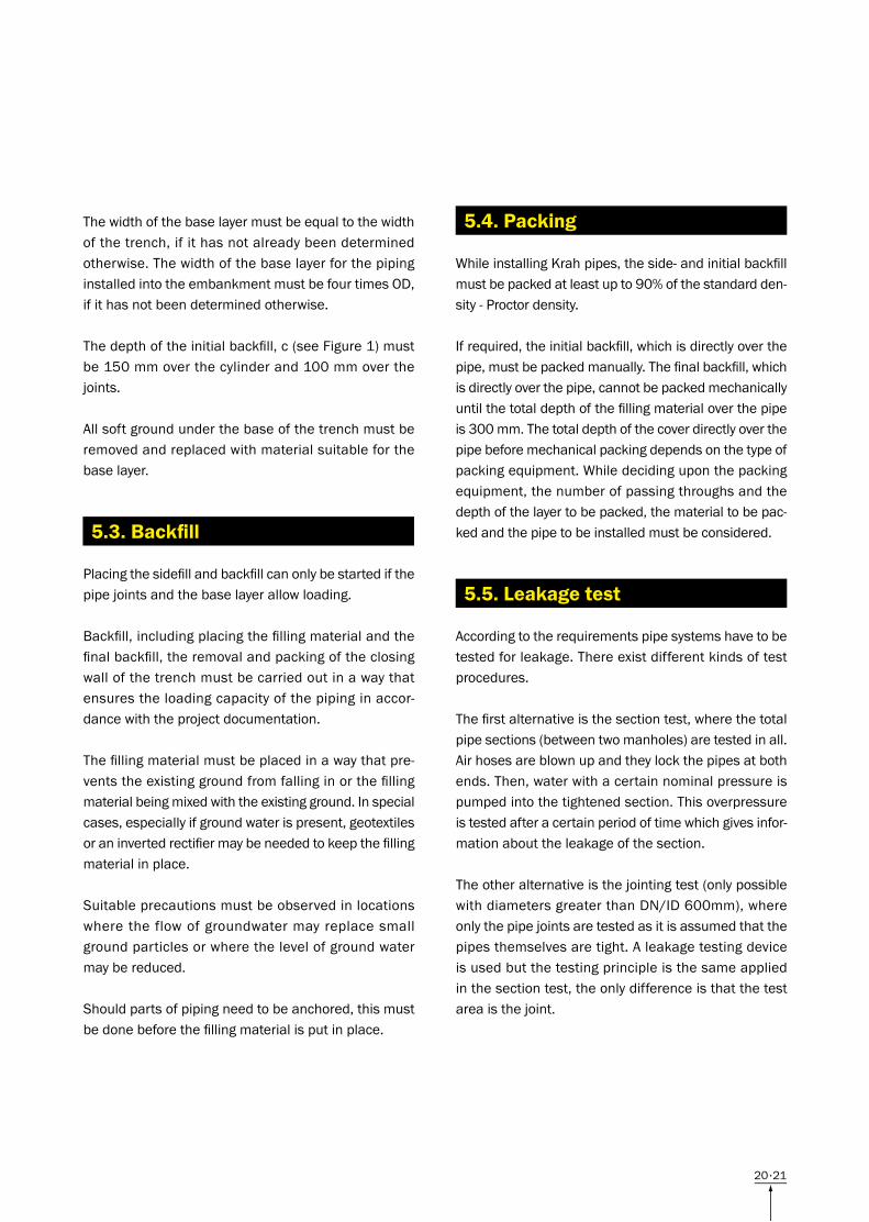
DN
Minimum width of trench (OD+x)m
Supported trenchUnsupported trench
ß > 60° ß ≤ 60°
≤ 225 OD + 0.40 OD + 0.40
> 225 to ≤ 350 OD + 0.50 OD + 0.50 OD + 0.40
> 350 to ≤ 700 OD + 0.70 OD + 0.70 OD + 0.40
> 700 to ≤ 1200 OD + 0.85 OD + 0.85 OD + 0.40
> 1200 OD + 1.00 OD + 1.00 OD + 0.40
Figure 1 – Minimum width of trench with respect to nominal size (DN). In the equation OD+x, x/2 equals the minimum working space between the pipe and the wall of the trench or supports, where: OD is the external diameter in meters and ß designates the angle of the unsupported wall of the trench, measured with respect to the horizontal (see Figure 2).
Depth of trench m
Minimum width of trench m
< 1.00 No minimum width required
≥ 1.00 ≤ 1.75 0.80
≥ 1.75 ≤ 4.00 0.90
> 4.00 1.00
Table 2 – Minimum width of trench with respect to depth of trench
Figure 2 - angle of unsupported wall of trench ß
5.1.2 Removal of water
5.2. Filling material and support
2120
WhileinstallingKrahpipes,theside-andinitialbackfillmustbepackedatleastupto90%ofthestandardden-sity-Proctordensity.
Ifrequired,theinitialbackfill,whichisdirectlyoverthepipe,mustbepackedmanually.Thefinalbackfill,whichisdirectlyoverthepipe,cannotbepackedmechanicallyuntilthetotaldepthofthefillingmaterialoverthepipeis300mm.Thetotaldepthofthecoverdirectlyoverthepipebeforemechanicalpackingdependsonthetypeofpackingequipment.Whiledecidinguponthepackingequipment,thenumberofpassingthroughsandthedepthofthelayertobepacked,thematerialtobepac-kedandthepipetobeinstalledmustbeconsidered.
Accordingtotherequirementspipesystemshavetobetestedforleakage.Thereexistdifferentkindsoftestprocedures.
Thefirstalternativeisthesectiontest,wherethetotalpipesections(betweentwomanholes)aretestedinall.Airhosesareblownupandtheylockthepipesatbothends.Then,waterwithacertainnominalpressureispumpedintothetightenedsection.Thisoverpressureistestedafteracertainperiodoftimewhichgivesinfor-mationabouttheleakageofthesection.
Theotheralternativeisthejointingtest(onlypossiblewithdiametersgreaterthanDN/ID600mm),whereonlythepipejointsaretestedasitisassumedthatthepipesthemselvesaretight.Aleakagetestingdeviceisusedbutthetestingprincipleisthesameappliedinthesectiontest,theonlydifferenceisthatthetestareaisthejoint.
Thewidthofthebaselayermustbeequaltothewidthofthetrench,ifithasnotalreadybeendeterminedotherwise.ThewidthofthebaselayerforthepipinginstalledintotheembankmentmustbefourtimesOD,ifithasnotbeendeterminedotherwise.
Thedepthoftheinitialbackfill,c(seeFigure1)mustbe150mmoverthecylinderand100mmoverthejoints.
Allsoftgroundunderthebaseofthetrenchmustberemovedandreplacedwithmaterialsuitableforthebaselayer.
Placingthesidefillandbackfillcanonlybestartedifthepipejointsandthebaselayerallowloading.
Backfill,includingplacingthefillingmaterialandthefinalbackfill,theremovalandpackingoftheclosingwallofthetrenchmustbecarriedoutinawaythatensurestheloadingcapacityofthepipinginaccor-dancewiththeprojectdocumentation.
Thefillingmaterialmustbeplacedinawaythatpre-ventstheexistinggroundfromfallinginorthefillingmaterialbeingmixedwiththeexistingground.Inspecialcases,especiallyifgroundwaterispresent,geotextilesoraninvertedrectifiermaybeneededtokeepthefillingmaterialinplace.
Suitableprecautionsmustbeobservedinlocationswheretheflowofgroundwatermayreplacesmallgroundparticlesorwherethelevelofgroundwatermaybereduced.
Shouldpartsofpipingneedtobeanchored,thismustbedonebeforethefillingmaterialisputinplace.
5.3. Backfill
5.4. Packing
5.5. Leakage test
22
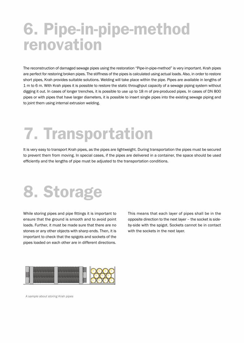
A sample about storing Krah pipes
6. Pipe-in-pipe-method renovationThereconstructionofdamagedsewagepipesusingtherestoration“Pipe-in-pipe-method”isveryimportant.Krahpipesareperfectforrestoringbrokenpipes.Thestiffnessofthepipesiscalculatedusingactualloads.Also,inordertorestoreshortpipes,Krahprovidessuitablesolutions.Weldingwilltakeplacewithinthepipe.Pipesareavailableinlengthsof1mto6m.WithKrahpipesitispossibletorestorethestaticthroughputcapacityofasewagepipingsystemwithoutdiggingitout.Incasesoflongertrenches,itispossibletouseupto18mofpre-producedpipes.IncasesofDN800pipesorwithpipesthathavelargerdiameters,itispossibletoinsertsinglepipesintotheexistingsewagepipingandtojointthemusinginternalextrusionwelding.
ItisveryeasytotransportKrahpipes,asthepipesarelightweight.Duringtransportationthepipesmustbesecuredtopreventthemfrommoving.Inspecialcases,ifthepipesaredeliveredinacontainer,thespaceshouldbeusedefficientlyandthelengthsofpipemustbeadjustedtothetransportationconditions.
7. Transportation
8. StorageWhilestoringpipesandpipefittingsitisimportanttoensurethatthegroundissmoothandtoavoidpointloads.Further,itmustbemadesurethattherearenostonesoranyotherobjectswithsharpends.Then,itisimportanttocheckthatthespigotsandsocketsofthepipesloadedoneachotherareindifferentdirections.
Thismeansthateachlayerofpipesshallbeintheoppositedirectiontothenextlayer–thesocketisside-by-sidewiththespigot.Socketscannotbeincontactwiththesocketsinthenextlayer.

2322
Thequalityassurancedemandsagreatknow-howandthereforetheKrahAGhascreatedaQualityhandbookinwhichalltheimportanttestsincludingthenecessarymachinesaredescribed.Inordertogivethecustomeranimpressionofthequalitycontrolitispossibletohavealookintothehandbook.
9. Quality controlTotal quality management
ThequalityofthepipesandthepipeproductsisthecriterionforalldevelopmentsofKrahAGandcompa-niesusingtheKrahtechnology.Astheinternationalrequirementsvarybecauseofthedifferentnormsandstandards,thereexistsamultiplicityoftestproceduresforthequalityassurance.ThewholeproductionprocessisincludedinanextensiveTotal-Quality-Management-System.Therearetwomainfields,theoneistheinternalqualitycontrolandtheotheristheexternal(third-party)qualitycontrol.
Generallytheinternalqualitycontrolisdividedintothreedifferentsteps:
1. BEFORE PRODUCTION CONTROL
Therawmaterialsandanyotherinputaretestedregardingthemeltingflowratio,moistureandcolour.Usuallyanynewdeliveryofmaterialistestedbeforeitisstored.Everytestisdocumented,analysedandfiled.
2. DURING PRODUCTION CONTROL
Duringtheproductiontheindividualworkingstepsarecontinouslysupervisedanddocumented.Moreoverthemostimportantdimensionsaremeasuredandifnecessary,corrected.
Inspection of ring stiffness
3. AFTER PRODUCTION CONTROL
Aftertheproduction,thefinalproductistestedandcomparedwiththerequirementsofthecustomer.Thefinalminuteiswrittenandthedocumentationisfinished.InordertoguaranteethatthestatictheoreticvaluesareconformtotherealitypipesarecontinuouslytakenoutoftheproductionandtheyaretestedwiththehelpofaringstiffnesstestaccordingtoDIN16961orISO9969.
Measuring the width of the pipe wall
24
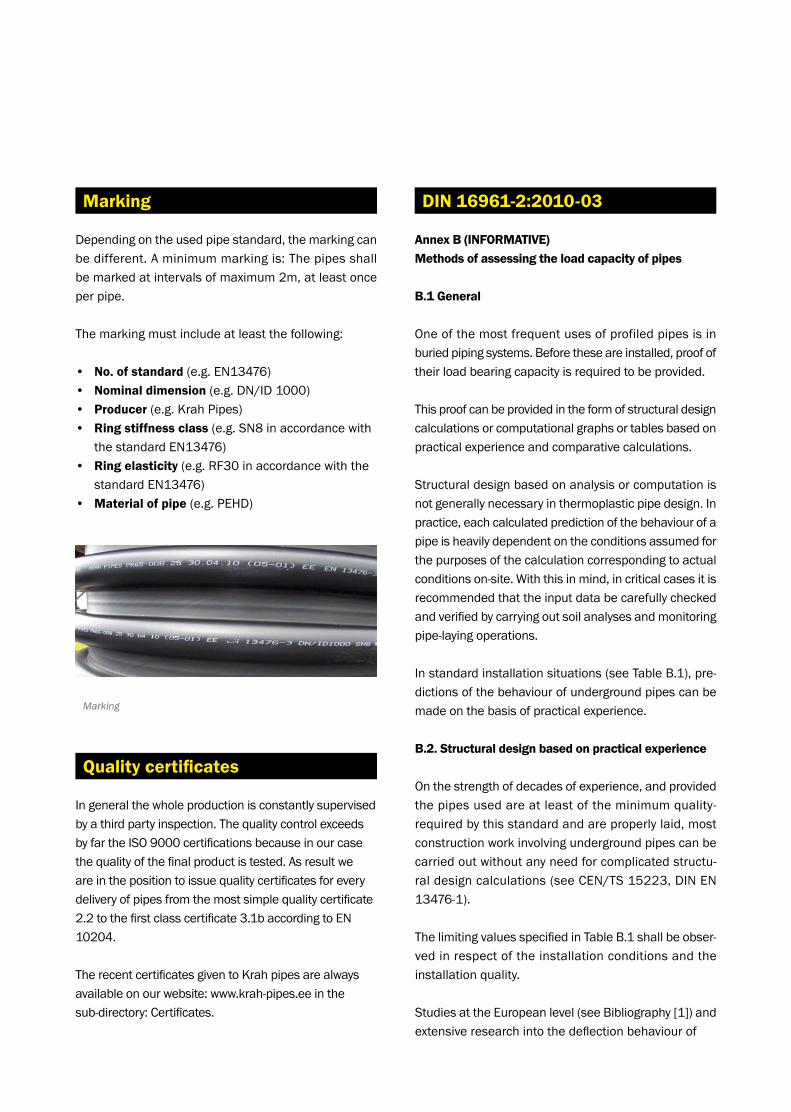
Dependingontheusedpipestandard,themarkingcanbedifferent.Aminimummarkingis:Thepipesshallbemarkedatintervalsofmaximum2m,atleastonceper pipe.
Themarkingmustincludeatleastthefollowing:
• No. of standard(e.g.EN13476)• Nominal dimension(e.g.DN/ID1000)• Producer(e.g.KrahPipes)• Ring stiffness class(e.g.SN8inaccordancewith
thestandardEN13476)• Ring elasticity(e.g.RF30inaccordancewiththe
standardEN13476)• Material of pipe(e.g.PEHD)
Ingeneralthewholeproductionisconstantlysupervisedbyathirdpartyinspection.ThequalitycontrolexceedsbyfartheISO9000certificationsbecauseinourcasethequalityofthefinalproductistested.Asresultweareinthepositiontoissuequalitycertificatesforeverydeliveryofpipesfromthemostsimplequalitycertificate2.2tothefirstclasscertificate3.1baccordingtoEN10204.
TherecentcertificatesgiventoKrahpipesarealwaysavailableonourwebsite:www.krah-pipes.eeinthe sub-directory:Certificates.
Quality certificates
Marking
Annex B (INFORMATIVE)Methods of assessing the load capacity of pipes
B.1 General
Oneofthemostfrequentusesofprofiledpipesisinburiedpipingsystems.Beforetheseareinstalled,proofoftheirloadbearingcapacityisrequiredtobeprovided.
Thisproofcanbeprovidedintheformofstructuraldesigncalculationsorcomputationalgraphsortablesbasedonpracticalexperienceandcomparativecalculations.
Structuraldesignbasedonanalysisorcomputationisnotgenerallynecessaryinthermoplasticpipedesign.Inpractice,eachcalculatedpredictionofthebehaviourofapipeisheavilydependentontheconditionsassumedforthepurposesofthecalculationcorrespondingtoactualconditionson-site.Withthisinmind,incriticalcasesitisrecommendedthattheinputdatabecarefullycheckedandverifiedbycarryingoutsoilanalysesandmonitoringpipe-layingoperations.
Instandardinstallationsituations(seeTableB.1),pre-dictionsofthebehaviourofundergroundpipescanbemadeonthebasisofpracticalexperience.
B.2. Structural design based on practical experience
Onthestrengthofdecadesofexperience,andprovidedthepipesusedareatleastoftheminimumquality-requiredbythisstandardandareproperlylaid,mostconstructionworkinvolvingundergroundpipescanbecarriedoutwithoutanyneedforcomplicatedstructu-raldesigncalculations(seeCEN/TS15223,DINEN13476-1).
ThelimitingvaluesspecifiedinTableB.1shallbeobser-vedinrespectoftheinstallationconditionsandtheinstallationquality.
StudiesattheEuropeanlevel(seeBibliography[1])andextensiveresearchintothedeflectionbehaviourof
DIN 16961-2:2010-03Marking

2524
KeyXRingstiffnessSN,inkN/m2
YGroundwaterlevelabovetheinvert,inm1Compaction“GOOD”2Compaction“AVERAGE”
Joonis B.2 – Maximum permissible groundwater level above the invert (GW) as in ATV-DVWK-A 127 (DWA-A 127 Code of practice)
NOTE 1TherelationshipbetweenSNandSR24asshowninFigureB.2,basedonpolyethylene,isintendedforguidance.Thecurvehasbeencalculatedassumingalayingdepthof6mandgoodlayingquality(seeTableB.1).Highergroundwaterlevelsarepermittedforpipeslaidatadepthlessthan6m.
NOTE 2“Good”and“average”compactionwith95%and90%standardProctordensityrespectivelyareusedforalltypesofgroundinwhichpipesareinstalled(i.e.includingnaturalground).OnlyinstallationcaseIasinATV-DVWK-A127isconsidered.Mixedsoilsofgroups1and2asinATV-DVWK-A127(DIN18196)are assumed.
AccordingtoCEN/TS15223,pipingsystemsofstiffnessclassesSN4orSR2416designedtobeusedunderg-roundaresufficientlyresistanttoexternalwaterpressu-re.ThemorestringentrequirementsofATV-DVWK-A127(DWA-A127)[3]withregardtoexternalwaterpressurecanbecheckedinFigureB.2asafunctionoftheringstiffnessofthepipe.
pipes in existing European pipe systems (seeBibliography[2])haveinvestigatedthesubjectofdef-lectionofundergroundpipes.Inthelatterstudy,actualdeflectionwasmeasuredseveraltimesoveraperiodof25years.ThefindingsofthetwostudieshaveresultedintheempiricalvaluesshowninFigureB.1.
FigureB.1illustratestheexpectedmaximumlong-termdeflectionofburiedpipesasafunctionofthelayingqualityandtheringstiffnessofthepipes.
KeyXRingstiffnessSN,inkN/m2
YLong-termdeflection,in%ACompaction“AVERAGE”BCompaction“GOOD”
Joonis B.1 – Long-term pipe deflection: maximum values
TheringstiffnessofapipeorfittingcannotbedirectlyconvertedfromtheSR24totheSNvalueandvice-versa.Duetotheinfluenceofvariousfactors:themodulusofelasticityoftherespectivematerial,thenominalsizeofthepipe,thevariousmethodsoftestingstiffnessandthedifferingdurationsofthetests,thevalueofringstiffnessisrequiredtobedeterminedindividuallybytesting.Practicehasshownthatthesefactorsdonothaveanymeasurableinfluenceontheactualdeflectionofpipesoncetheyarelaid.
Theringstiffnessvalues<SN4(SR2416)showninthediagramsaremostfrequentlyfoundinlargepipes.
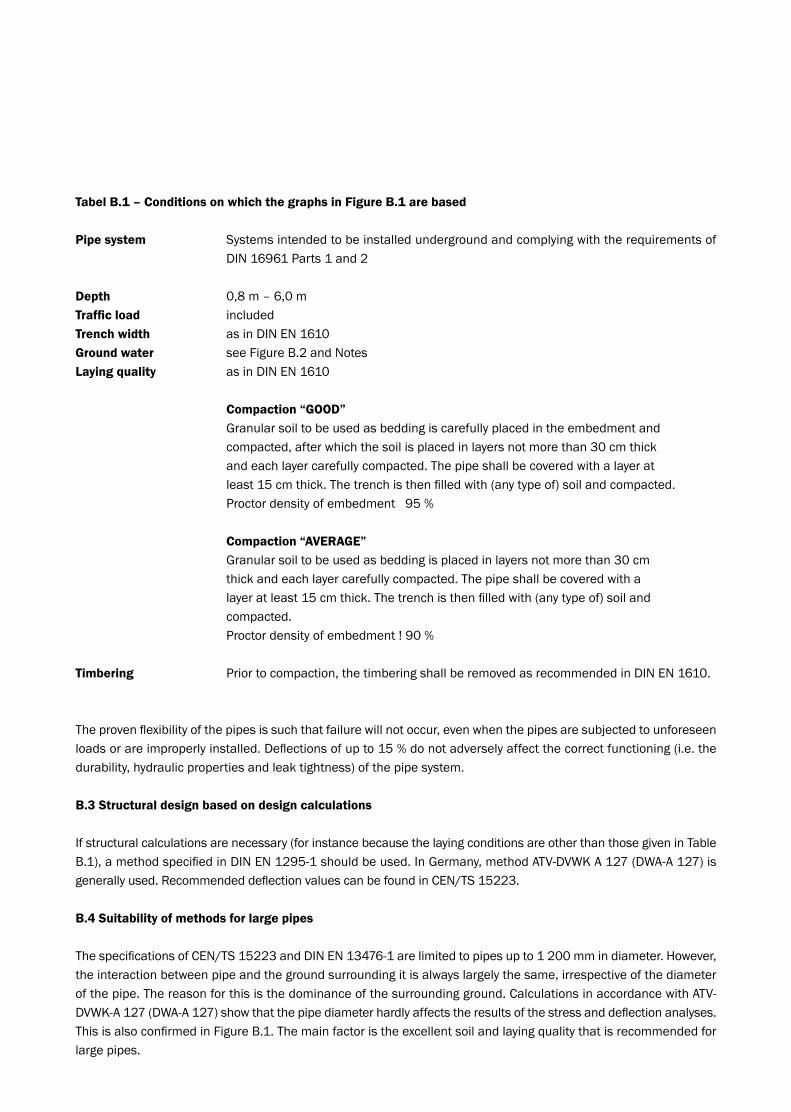
Tabel B.1 – Conditions on which the graphs in Figure B.1 are based
Pipe system Systemsintendedtobeinstalledundergroundandcomplyingwiththerequirementsof DIN16961Parts1and2
Depth 0,8m–6,0mTraffic load includedTrench width asinDINEN1610Ground water seeFigureB.2andNotesLaying quality asinDINEN1610
Compaction “GOOD” Granularsoiltobeusedasbeddingiscarefullyplacedintheembedmentand compacted,afterwhichthesoilisplacedinlayersnotmorethan30cmthick andeachlayercarefullycompacted.Thepipeshallbecoveredwithalayerat least15cmthick.Thetrenchisthenfilledwith(anytypeof)soilandcompacted. Proctordensityofembedment95%
Compaction “AVERAGE” Granularsoiltobeusedasbeddingisplacedinlayersnotmorethan30cm thickandeachlayercarefullycompacted.Thepipeshallbecoveredwitha layeratleast15cmthick.Thetrenchisthenfilledwith(anytypeof)soiland compacted. Proctordensityofembedment!90%
Timbering Priortocompaction,thetimberingshallberemovedasrecommendedinDINEN1610.
Theprovenflexibilityofthepipesissuchthatfailurewillnotoccur,evenwhenthepipesaresubjectedtounforeseenloadsorareimproperlyinstalled.Deflectionsofupto15%donotadverselyaffectthecorrectfunctioning(i.e.thedurability,hydraulicpropertiesandleaktightness)ofthepipesystem.
B.3 Structural design based on design calculations
Ifstructuralcalculationsarenecessary(forinstancebecausethelayingconditionsareotherthanthosegiveninTableB.1),amethodspecifiedinDINEN1295-1shouldbeused.InGermany,methodATV-DVWKA127(DWA-A127)isgenerallyused.RecommendeddeflectionvaluescanbefoundinCEN/TS15223.
B.4 Suitability of methods for large pipes
ThespecificationsofCEN/TS15223andDINEN13476-1arelimitedtopipesupto1200mmindiameter.However,theinteractionbetweenpipeandthegroundsurroundingitisalwayslargelythesame,irrespectiveofthediameterofthepipe.Thereasonforthisisthedominanceofthesurroundingground.CalculationsinaccordancewithATV-DVWK-A127(DWA-A127)showthatthepipediameterhardlyaffectstheresultsofthestressanddeflectionanalyses. ThisisalsoconfirmedinFigureB.1.Themainfactoristheexcellentsoilandlayingqualitythatisrecommendedforlargepipes.


Gaasitee11/75306Raevald/Harjumaa/Eesti/Tel:+3726841050/Fax:+3726841051/[email protected]/www.krah-pipes.ee