Technical Information - SMA HYBRID CONTROLLER
74
Parameter-HyCon-TI-en-11 | Version 1.1 ENGLISH Technical Information SMA HYBRID CONTROLLER Parameters and display values
Transcript of Technical Information - SMA HYBRID CONTROLLER

Parameter-HyCon-TI-en-11 | Version 1.1ENGLISH
Technical InformationSMA HYBRID CONTROLLERParameters and display values

Legal Provisions SMA Solar Technology AG
Technical InformationParameter-HyCon-TI-en-112
Legal ProvisionsThe information contained in these documents is the property of SMA Solar Technology AG. No part of this documentmay be reproduced, stored in a retrieval system, or transmitted, in any form or by any means, be it electronic,mechanical, photographic, magnetic or otherwise, without the prior written permission of SMA Solar Technology AG.Internal reproduction used solely for the purpose of product evaluation or other proper use is allowed and does notrequire prior approval.SMA Solar Technology AG makes no representations or warranties, express or implied, with respect to thisdocumentation or any of the equipment and/or software it may describe, including (with no limitation) any impliedwarranties of utility, merchantability, or fitness for any particular purpose. All such representations or warranties areexpressly disclaimed. Neither SMA Solar Technology AG nor its distributors or dealers shall be liable for any indirect,incidental, or consequential damages under any circumstances.The exclusion of implied warranties may not apply in all cases under some statutes, and thus the above exclusion maynot apply.Specifications are subject to change without notice. Every attempt has been made to make this document complete,accurate and up-to-date. Readers are cautioned, however, that product improvements and field usage experience maycause SMA Solar Technology AG to make changes to these specifications without advance notice or per contractprovisions. SMA Solar Technology AG shall not be responsible for any damages, including indirect, incidental orconsequential damages, caused by reliance on the material presented, including, but not limited to, omissions,typographical errors, arithmetical errors or listing errors in the content material.
Software licensesYou will find the software licenses for the installed software modules on the Internet at www.SMA-Solar.com.
TrademarksAll trademarks are recognized, even if not explicitly identified as such. Missing designations do not mean that aproduct or brand is not a registered trademark.
SMA Solar Technology AGSonnenallee 134266 NiestetalGermanyTel. +49 561 9522-0Fax +49 561 9522-100www.SMA.deEmail: [email protected] of: 6/29/2021Copyright © 2021 SMA Solar Technology AG. All rights reserved.

Table of ContentsSMA Solar Technology AG
Technical Information 3Parameter-HyCon-TI-en-11
Table of Contents1 Information on this Document..................................................................................................... 5
1.1 Validity ............................................................................................................................................................. 51.2 Target Group ................................................................................................................................................... 51.3 Typographical Elements in the Document ...................................................................................................... 51.4 Designations in the Document ........................................................................................................................ 51.5 Explanation of Used Terms ............................................................................................................................. 61.6 Additional Information..................................................................................................................................... 6
2 Parameters for Communication with SCADA System ............................................................... 7
3 Display Values.............................................................................................................................. 103.1 Overview of Operating Modes and Setpoints .............................................................................................. 103.2 Display Values of the Entire Hybrid System................................................................................................... 123.3 Display Values of the Gensets ........................................................................................................................ 173.4 Display Values of the PV Power Plant ............................................................................................................ 183.5 Storage System Display Values ...................................................................................................................... 193.6 Display Values of the Measurement Devices................................................................................................. 203.7 Performance Diagrams of the PV Diesel Hybrid System ............................................................................... 213.8 Display Values and Functions for Battery-Powered Operation .................................................................... 233.9 Display Values for SCADA System................................................................................................................. 253.10 Display values for external interpolation points ............................................................................................ 263.11 Display values for ripple control receivers and communication in accordance with IEC 60807.............. 263.12 Device Information .......................................................................................................................................... 27
4 System Settings............................................................................................................................. 284.1 Parameters for the Utility Grid ........................................................................................................................ 284.2 Adjustable parameters for gensets in the Hybrid Controller......................................................................... 29
4.2.1 Parameters for Gensets with the Genset Controller AGC ............................................................................. 294.2.2 Parameters for Gensets with Genset Controller ComAp InteliGen NTC or ComAp InteliSys NTC ........... 304.2.3 Parameters for Gensets with Genset Controller DSE8610 ........................................................................... 324.2.4 Parameters for gensets with genset controller easYgen-3000 via the CAN network ................................. 334.2.5 Parameters for Gensets with Genset Controller easYgen-3000 via the ESENET Gateway ....................... 354.2.6 Parameters for Gensets with the Genset Controller GENSYS 2.0 ............................................................... 364.2.7 Parameters for Gensets without the Genset Controller.................................................................................. 38
4.3 Settings on the Genset Controllers ................................................................................................................. 394.3.1 Settings on ComAp InteliGen NTC or ComAp InteliSys NTC Genset Controllers ...................................... 394.3.2 Settings on DSE8610 Genset Controllers or DSE8610 MKII ...................................................................... 424.3.3 Settings on easYgen 3000 Genset Controllers ............................................................................................. 424.3.4 Settings on the Genset Controllers GENSYS 2.0 .......................................................................................... 44
4.4 Parameters for the PV Power Plant ................................................................................................................. 454.5 Parameters for the Storage System ................................................................................................................ 464.6 Settings on the Measurement Devices ........................................................................................................... 47
4.6.1 General Settings on Measurement Devices ................................................................................................... 474.6.2 Detailed Settings on Measurement Devices for Internal Measurement Modules of the Hybrid
Controller .......................................................................................................................................................... 484.6.3 Detailed Settings on Measurement Devices for Data Acquisition Modules................................................. 49
4.7 Settings on the Temperature and Irradiation Sensors ................................................................................... 514.8 User-defined settings at digital inputs and outputs ........................................................................................ 52
5 System Control ............................................................................................................................. 55

Table of Contents SMA Solar Technology AG
Technical InformationParameter-HyCon-TI-en-114
5.1 Control of PV and battery inverters ................................................................................................................ 555.1.1 Control of the PV Power Plant Reactive Power According to Electrical Consumption................................. 555.1.2 State-Of-Charge Control of the Battery .......................................................................................................... 57
5.2 Processing of the received measured values and parameters...................................................................... 585.2.1 Selecting a Measuring Point for Control ........................................................................................................ 585.2.2 Other Parameters for Processing the Received Measured Values and Parameters .................................... 59
5.3 Calculation of the parameters to be output ................................................................................................... 605.3.1 Setpoint Change Rate for PV Inverters and Gensets ..................................................................................... 605.3.2 Options for Specifying the Reserve Power Setpoint of the Gensets ............................................................. 635.3.3 Conditions for the Connection and Disconnection of the PV Inverters ......................................................... 645.3.4 Distribution of setpoints among the PV inverter .............................................................................................. 645.3.5 Distribution of setpoints among the battery inverters ..................................................................................... 655.3.6 Distribution of setpoints among all PV inverters ............................................................................................. 68
5.4 Battery-supported operation .......................................................................................................................... 685.4.1 Parameters for PV Yield Forecast .................................................................................................................... 685.4.2 Parameters for Frequency Control .................................................................................................................. 695.4.3 Parameters for Voltage Control....................................................................................................................... 705.4.4 Parameter for black start.................................................................................................................................. 71
5.5 Functions for grid support ............................................................................................................................... 715.5.1 General Functions for Grid Support ............................................................................................................... 715.5.2 Parameter for SOC Management of Battery Inverter.................................................................................... 73

1 Information on this DocumentSMA Solar Technology AG
Technical Information 5Parameter-HyCon-TI-en-11
1 Information on this Document1.1 ValidityThis document is valid for:
• HYBRID-CONTROLLER (SMA Hybrid Controller) from software version 2.12• HYBRID-CONTROLLER (SMA Hybrid Controller), assembly unit on DIN rail
1.2 Target Group• Training in the installation and configuration of IT systems• Knowledge of how the product works and is operated• Training in how to deal with the dangers and risks associated with installing, repairing and using electrical devices
and installations• Training in the installation and commissioning of electrical devices and installations• Knowledge of all applicable laws, standards and directives• Knowledge of and compliance with this document and all safety information
1.3 Typographical Elements in the DocumentTypography Use Example
bold • Messages• Terminals• Elements on a user interface• Elements to be selected• Elements to be entered
• Connect the insulated conductorsto the terminals X703:1 toX703:6.
• Enter 10 in the field Minutes.
> • Connects several elements to beselected
• Select Settings > Date.
[Button][Key]
• Button or key to be selected or pressed • Select [Enter].
# • Placeholder for variable components(e.g., parameter names)
• Parameter WCtlHz.Hz#
1.4 Designations in the DocumentComplete designation Designation in this document
SMA Hybrid Controller Hybrid Controller, product
SMA Hybrid Controller as assembly unit on DIN rail Assembly unit
SMA Hybrid Controller as switch cabinet SMA switch cabinet
SMA Solar Technology AG SMA
Sunny Tripower, Sunny Central PV inverter
Sunny Tripower Storage, Sunny Central Storage Battery inverter

1 Information on this Document SMA Solar Technology AG
Technical InformationParameter-HyCon-TI-en-116
1.5 Explanation of Used TermsTerm Explanation
Genset Electric generator with combustion engine
Genset controller System for the regulation and control of electric generators with combustion en-gine
Hybrid system System for the control of energy flows based on a programmable logic controller(e.g. SMA Hybrid Controller or Power Plant Manager)Various energy sources can be integrated into a hybrid system (e.g. PV powerplant, genset or battery-storage system).
1.6 Additional InformationFor more information, please go to www.SMA-Solar.com.
Title and information content Type of information
Operation, configuration and troubleshooting User Manual
"PUBLIC CYBER SECURITY - Guidelines for a Secure PV System Communication" Technical information
"Parameters and Measured Values"Overview of all inverter operating parameters and their configuration options
Technical Information
"SMA HYBRID CONTROLLER Modbus® Interface"Information on the commissioning and configuration of the SMA Modbus inter-face
Technical Information
"Use of Gensets in hybrid systems with SMA Hybrid Controller"Communication interface requirements and Genset Controller configuration
Technical Information

2 Parameters for Communication with SCADA SystemSMA Solar Technology AG
Technical Information 7Parameter-HyCon-TI-en-11
2 Parameters for Communication with SCADA SystemPath: Home > Settings > SCADA Settings
Parameters Description Value Explanation Default value
EnaWrite Enables the write access ofSCADA system to the Hy-brid Controller
Disabled Write access is disabled. Disabled
SCADA1 SCADA1 write access isenabled.
SCADA2 SCADA2 write access isenabled.
Port SCADA1 Port of Modbus/TCP connectionfor SCADA1The ports for SCADA1 andSCADA2 must be different fromeach other.
1 to 65535 - 503
Port SCADA2 Port of Modbus/TCP connectionfor SCADA2The ports for SCADA1 andSCADA2 must be different fromeach other.
1 to 65535 - 504
FallbackMode Fallback level in the event of com-munication problems
Fallback set-point
The Hybrid Controllerchanges the setpoints start-ing with FlbSubVal aftersetting the parameters. Allof these parameters can befound on this page.
Fallback set-point
Last setpoint The Hybrid Controller re-tains the setpoints that werevalid before the communi-cation fault.
Go to Stop The Hybrid Controllerstops.
Go to Error The Hybrid Controllerswitches to the operatingstate ERROR. Automaticoperation of the hybrid sys-tem is interrupted.
FallbackErrTm Timeout for return to fallbacklevelIf FallbackMode is set to Go toError, this parameter applies.
0 s to 86400 s - 60 s

2 Parameters for Communication with SCADA System SMA Solar Technology AG
Technical InformationParameter-HyCon-TI-en-118
Parameters Description Value Explanation Default value
Fallback-MonTm
Timeout for return to fallbacklevelIf FallbackMode is set to Fall-back setpoint, Last setpointand Go to Stop, this parameterapplies.
5 s to 86400 s - 5 s
FlbRun This parameter specifies how theHybrid Controller has to behavewhen the communication of theSCADA system is interrupted.
STOP The Hybrid Controllerswitches to the operatingstate STANDBY.
STOP
RUN The Hybrid Controllerswitches to the operatingstate OPERATE.
FlbSubValP-wrAt
Predefined setpoint for activepower of battery inverter, validduring time-out
-100000 kWto+100000 kW
- 0 kW
FlbSubValPwrRt Predefined setpoint for reactivepower of all battery inverters,valid during time-out
-100000 kVArto+100000 kVAr
- 0 kvar
FlbSubValVt-gSpnt
Predefined setpoint for outputvoltage, valid during time-out
0 V to220000 V
- 400 V
FlbSubVal-CosPhiSpnt
Predefined setpoint for cos phi ofall inverters, valid during time-out
-1.000 to+1.000
- 1.000
FlbSubValP-wrAtApr
Predefined setpoint for active-power reserve of PV inverters,valid during time-out
0 kW to1000000 kW
- 0 kW
FlbSubValP-wrAtLimHi
Predefined upper active-powerlimit of all inverters, valid duringtime-out
-1000000 kWto+1000000 kW
- 0 kW
FlbSubValP-wrAtLimLo
Predefined lower active-powerlimit of all inverters, valid duringtime-out
-1000000 kWto+1000000 kW
- 0 kW
FlbSubValP-wrAtLimSale
Predefined upper active-powerlimit of the direct seller, valid dur-ing time-out
-1000000 kWto+1000000 kW
- 0 kW
FlbSubValP-wrAtMpp
Predefined maximum power pointof PV inverters, valid during time-out for all inverters
0 kW to1000000 kW
- 0 kW
FlbSubValP-wrAtRateMax
Predefined rate of change of ac-tive power, valid during time-out
0.001 MW/min to1000000 MW/min
- 1 MW/min

2 Parameters for Communication with SCADA SystemSMA Solar Technology AG
Technical Information 9Parameter-HyCon-TI-en-11
Parameters Description Value Explanation Default value
FlbSubValPwr-RtRateMax
Predefined rate of change of re-active power, valid during time-out
0.001 Mvar/min to 1000000 Mvar/min
- 1 Mvar/min
FlbSubValP-wrApLim
Predefined apparent-power limitof all inverters, valid during time-out
0 kVA to1000000 kVA
- 0 kVA
FlbSubValPwr-RtLimHi
Predefined upper reactive-powerlimit of all inverters, valid duringtime-out
-1000000 kVAr to+1000000 kVAr
- 0 kVAr
FlbSubValPwr-RtLimLo
Predefined lower reactive-powerlimit of all inverters, valid duringtime-out
-1000000 kVAr to+1000000 kVAr
- 0 kVAr

3 Display Values SMA Solar Technology AG
Technical InformationParameter-HyCon-TI-en-1110
3 Display Values3.1 Overview of Operating Modes and SetpointsPath: Home > Operations > Mode
BA
C
Figure 1: Overview of current operating state of the product (example)

3 Display ValuesSMA Solar Technology AG
Technical Information 11Parameter-HyCon-TI-en-11
Position Display group Parameters /Functions
Description
A Change controlmode
Current opera-tion
Shows the current operating mode:• Automatic mode (see Enable automatic mode)
The Hybrid Controller normally operates in Automaticmode.The Hybrid Controller calculates the setpoints for the PVpower plant, the battery and the reserve power to beretained by the gensets.
• Manual mode (see Enable manual mode)Manual mode is normally used only when theHybrid Controller is being commissioned. In Manualmode, the reserve power to be kept by the gensets isspecified via the user interface.If the Hybrid Controller remains 15 minutes in theoperating mode Manual and no user is logged in, theHybrid Controller switches automatically to the operatingstate SLOW STOP and then to the Standby mode.
• SLOW STOP modeThe Hybrid Controller stops the PV inverter (seeHybrid Controller user manual).
Enable auto-matic mode
Enable operating mode Automatic (see Hybrid Controller usermanual)
Enable manualmode
Enable operating mode Manual (see Hybrid Controller usermanual)
B System setpoints /system recommenda-tion
Genset reservepower
Current setpoint for the reserve power of the gensets in kW*
PV activepower
Current setpoint for the active power of the PV power plant inkW*
PV reactivepower
Current setpoint for the reactive power of the PV power plant inkvar*
Battery activepower
Current setpoint for the active power of the storage system inkW*
Battery reactivepower
Current setpoint for the reactive power of the storage system inkVAr*

3 Display Values SMA Solar Technology AG
Technical InformationParameter-HyCon-TI-en-1112
Position Display group Parameters /Functions
Description
C Live values Calculated sys-tem load
Calculated active power requirement of the loads in kW
Running gensetcapacity
Sum of rated power of all active gensets in kW
PV production Active power of the PV power plant in kW
Genset powerproduction
Active power of the gensets in kW
Available spin-ning reserve
Current reserve power of the gensets in kW
Battery activepower
Active power of the storage system in kW
* The Hybrid Controller would currently send this setpoint if the Hybrid Controller were in automatic mode.
3.2 Display Values of the Entire Hybrid SystemThe most important display values of the entire hybrid system can be found on the Hybrid Plant Overview page viathe following registers:
• Power: Display values of the electrical power• Energy: Display values of the electrical energy
Path: Home > Stations > General Overview

3 Display ValuesSMA Solar Technology AG
Technical Information 13Parameter-HyCon-TI-en-11
Power: Instantaneous value of the electrical power
AH
FB
C
D
G
E
Figure 2: Power: Overview of electrical power (example)
Position Display group Display value Description
A Electrical loads Active power Current active power of the loads
Reactive power Current reactive power of the loads

3 Display Values SMA Solar Technology AG
Technical InformationParameter-HyCon-TI-en-1114
Position Display group Display value Description
B State of the dynamicgenset control (Dy-namic Genset Shut-down)
Current plant state State of the dynamic genset control (DynamicGenset Shutdown):
• Idle: Hybrid system is out of operation.• Genset operation: Gensets are in operation.• Battery operation: Storage system is in
operation.
Current transition Transition of the dynamic genset control:• Idle: State of the dynamic genset control is
stable. There is currently no transition.• Genset unloading: Performance requirement
for the gensets is being reduced.• Genset shutdown: Gensets are disconnected
form the local utility grid and switched off.• Genset start preparation: Voltage and
frequency of the local utility grid aresynchronized with the gensets
• Genset start: Gensets are started.
Battery in process Operating hours of the storage system of the currentday
Genset in process Operating hours of the gensets of the current day
Mains op. process Duration of purchased electricity on the current day
C Distribution of electricalpower
Total active power Active power currently consumed by the loads
Genset power Share of genset active power currently consumed bythe loads
PV power Share of PV power plant active power currently con-sumed by the loads
Battery power Share of storage system active power currently con-sumed by the loads
Grid power Share of utility grid active power currently consumedby the loads
D Irradiation and temper-ature sensors
Ambient temp. Ambient temperature
Module temp. Temperature of the PV modules
Global irradiation PV irradiation
Power MPP Active power output at the maximum power point
3 Display ValuesSMA Solar Technology AG
Technical Information 15Parameter-HyCon-TI-en-11
Position Display group Display value Description
E Utility grid MCB status* Status of the connection to the utility grid:• OPEN: Connection is open.• CLOSED: Connection is closed.
Active power Current active power of the utility grid
Reactive power Current reactive power of the utility grid
F Storage system Active Power Current active power of the storage system
Reactive power Current reactive power of the storage system
State of charge State of charge of the battery
G Gensets Active power Current active power of the gensets in kW
Reactive power Current reactive power of the gensets in kvar
Reserve power setpoint Setpoint for the reserve power of the gensets
H PV power plant Active power Current active power of the PV power plant in kW
Reactive power Current reactive power of the PV power plant in kvar
* MCB: Main Control Block (control unit of control system)

3 Display Values SMA Solar Technology AG
Technical InformationParameter-HyCon-TI-en-1116
Energy: Instantaneous values of the electrical energy
AF
B
D
C
E
Figure 3: Power: Overview of electrical energy (example)
Position Display group Display value Description
A Electrical loads Consumed energy Energy consumption of loads: What is the period towhich this information relates?
B Distribution of electricalenergy
Total energy Energy currently consumed by the loads
Genset energy Share of genset energy consumed by the loads
PV energy Share of the load energy consumption supplied bythe PV power plant
Battery energy Share of storage system energy currently consumedby the loads
Mains energy Share of utility grid energy currently consumed bythe loads
C Utility grid Energy delivered Energy fed into the utility grid
Consumed energy Grid-supplied energy
D Storage system Delivered Energy Energy drawn from the storage system
Consumed energy Energy delivered to the storage system (for batterycharging)

3 Display ValuesSMA Solar Technology AG
Technical Information 17Parameter-HyCon-TI-en-11
Position Display group Display value Description
E Gensets Energy delivered Energy delivered by gensets
F PV power plant Energy delivered Energy delivered by the PV power plant
3.3 Display Values of the GensetsThe page Generator system overview shows the display values of all gensets in the hybrid system. The gensetnames are assigned at the time of commissioning.Path: Home > Stations > Genset System
Display value Description Value Explanation
Selected genset Currently displayed genset – –
Rated power Rated power of the selected genset – –
Active power Current active power of the selectedgenset
– –
Reactive power Current reactive power of the selectedgenset
– –
Apparent power Current apparent power of the selectedgenset
– –
Power factor Power factor: specifies the ratio of ac-tive power to apparent power.
– –
AC voltage Current AC voltage of the selectedgenset
– –
Operation time Operation time of the selected gensetsince first commissioning
– –
Energy fed in Grid feed-in: Energy fed into the localutility grid
– –
DevState Operating mode of the selected genset STOP Genset is out of service (e.g., formaintenance work)
IN OPERA-TION
Genset is in operation.
ERROR An error has occurred in thegenset.
WAIT Genset is in waiting mode.
WARNING A warning has occurred in thegenset.
COM ERROR Communication between gensetcontroller and Hybrid Controllerhas failed.

3 Display Values SMA Solar Technology AG
Technical InformationParameter-HyCon-TI-en-1118
Display value Description Value Explanation
Mode Operating mode of the selected genset STOP Genset is out of service (e.g., formaintenance work)
MANUAL Genset is in manual mode.
AUTO Genset is in automatic mode andcan be activated by means of theautostart signal.
LDSS The genset is enabled and dis-abled via the genset system’spower management function.
GCB status Current status of the circuit breakersthat connect the genset to the local util-ity grid.
CLOSED The genset is connected to the lo-cal utility grid.
OPEN The genset is not connected tothe local utility grid.
3.4 Display Values of the PV Power PlantThe most important display values of the entire hybrid system can be found on the Photovoltaic system overviewpage.Path: Home > Stations > PV System
Display value Description Value Explanation
Selected inverter Currently displayed inverter – –
Rated power Rated power of the inverter – –
Active power Current active power of the in-verter
– –
Reactive power Current reactive power of the in-verter
– –
Active power setpoint Setpoint for the current activepower as a ratio of rated power,in %
– –
Reactive power set-point
Setpoint for the current reactivepower as a ratio of rated power,in %
– –
AC voltage AC output voltage of the inverter – –
DC voltage DC input voltage of the inverterin V
– –
Energy fed in Grid feed-in: Energy fed into thelocal utility grid in MWh
– –
3 Display ValuesSMA Solar Technology AG
Technical Information 19Parameter-HyCon-TI-en-11
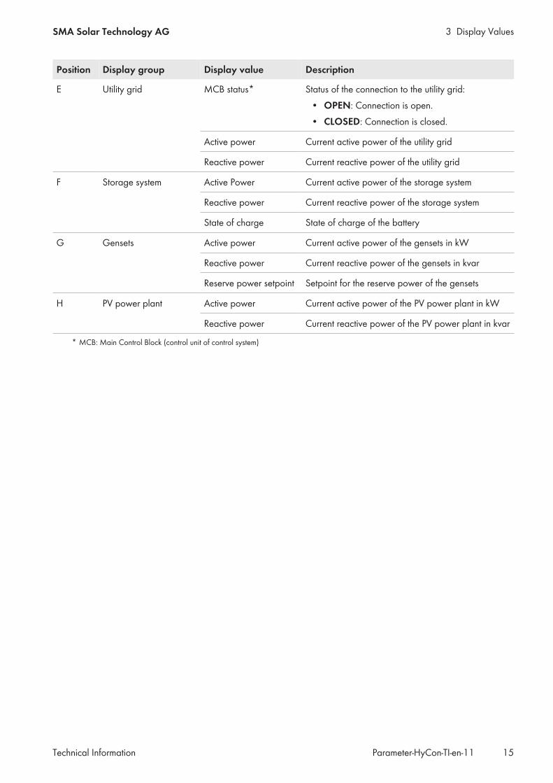
Display value Description Value Explanation
Operational state Current operating mode of the in-verter
STOP The inverter is switched off.
WAIT FOR DC The inverter is waiting for DC in-put voltage.
WAIT FOR AC The inverter is waiting for anavailable local grid at the ACoutput.
COM ERROR Communication between inverterand Hybrid Controller has failed.
WAIT FOR SET-POINT
The inverter is waiting for a set-point from the Hybrid Controller.
IN OPERATION The inverter is feeding in.
WARNING A warning has occurred in the in-verter.
ERROR An error has occurred in the in-verter.
Q ON DEMAND The inverter is in the operatingstate "Q on Demand".
Device Error Error in the inverter – See inverter documentation
Serial number Inverter serial number – –
3.5 Storage System Display ValuesThe display values can only be retrieved on this page if a battery inverter has been installed.Path: Home > Stations > Battery
Display value Description Value Explanation
Selected inverter Currently displayed battery in-verter
– –
State of Charge(SOC)
State of charge of the battery – –
Active Power Current active power of the bat-tery inverter
– –
Reactive Power Current reactive power of thebattery inverter
– –
Active power setpoint Setpoint for the active power ofthe battery inverter
– –
Reactive power set-point
Setpoint for the reactive power ofthe battery inverter
– –
Maximum activepower charge
Maximum charge power of thebattery inverter
– –

3 Display Values SMA Solar Technology AG
Technical InformationParameter-HyCon-TI-en-1120
Display value Description Value Explanation
Maximum activepower discharge
Maximum discharge power ofthe battery inverter
– –
AC frequency Frequency – –
BSC operation modestatus
Operating mode of the BatterySystem ControllerThe Battery System Controller isthe communication interface ofthe battery inverter to the BatteryManagement System and the Hy-brid Controller.
STOP The storage system is switchedoff.
WAIT The storage system is verifying itsconnection conditions.
PQ The storage system is connectedand is processing the active andreactive power setpoints.
FAILURE An error has occurred in the stor-age system.
UNKNOWN The status of the storage systemcannot be read.
Device status Status of the battery inverter STOP The battery inverter is switchedoff.
IN OPERATION The battery inverter is feeding in.
ERROR An error has occurred in the bat-tery inverter.
WAIT The battery inverter is waiting forsetpoints.
WARNING A warning has occurred in thebattery inverter.
COM ERROR An error has occurred in the com-munication between the batteryinverter and the Hybrid Con-troller.
Device error code Storage system error For information on potential causes or corrective mea-sures, see the documentation for the battery inverter
3.6 Display Values of the Measurement DevicesThe values obtained from the connected measurement systems are displayed on the Measurement systemoverview page.Path: Home > Stations > Measurements
Display value Description Value Explanation
Selected measure-ment device
Currently displayed measurementsystem
Internal Measure-ment
Measurement devices connecteddirectly to the product.
DAQ Measurement devices connectedto the product via a Data Acquisi-tion Module.

3 Display ValuesSMA Solar Technology AG
Technical Information 21Parameter-HyCon-TI-en-11
Display value Description Value Explanation
Active power Calculated total active power – –
Active power L1/L2/L3
Calculated active power for L1/L2/L3
– –
Reactive power Calculated reactive power inkvar
– –
Reactive power L1/L2/L3
Calculated reactive power forL1/L2/L3 in kvar
– –
Apparent power Current apparent power of themeasuring device
– –
cos φ L1/L2/L3 Calculated power factor for L1/L2/L3
– –
Voltage L1-2/L2-3/L3-1
Measured voltage for L1/L2/l3 – –
Frequency Measured frequency – –
Energy consumed Energy consumption – –
Energy delivered Energy generation – –
Digital Input #1 sta-tus
Status of the digital input 1 on theData Acquisition Module
OPEN The digital input is switched off(contact is open).
CLOSED The digital input is switched on(contact is closed).
Digital Input #2 sta-tus
Status of the digital input 2 on theData Acquisition Module
OPEN The digital input is switched off(contact is open).
CLOSED The digital input is switched on(contact is closed).
List of measured de-vices
List containing all the devices inthe hybrid system to which thecurrently displayed measurementdevice is assigned.
– –
3.7 Performance Diagrams of the PV Diesel Hybrid SystemThe Historical Data page depicts a selection of power values over time. Different analysis periods can be selectedhere:
• the last minute (Show last minute)• the last 5 minutes (Show last 5 minutes)• the last hour (Show last hour)• the last 24 hours (Show last day)
Path: Home > Visualizations > Power Chart
Display value Description
Engaged nominal genset power Sum of nominal power of all active gensets

3 Display Values SMA Solar Technology AG
Technical InformationParameter-HyCon-TI-en-1122
Display value Description
Mains active power Active power of utility grid
Load active power Active power consumed by the loads
Genset active power Active power supplied by the gensets
PV active power Active power of the PV power plant
Battery active power Active power supplied by the storage system

3 Display ValuesSMA Solar Technology AG
Technical Information 23Parameter-HyCon-TI-en-11
3.8 Display Values and Functions for Battery-Powered OperationPath. Home > Visualizations > Battery-Powered Operation
A
B
D
E
CC
Figure 4: Overview of Battery-Powered Operation page

3 Display Values SMA Solar Technology AG
Technical InformationParameter-HyCon-TI-en-1124
Position Category Display value / but-ton / function
Description
A Boundary Conditions Short-Circuit Current Short-Circuit CurrentTo trigger fuses and circuit breakers, a minimumshort-circuit current must always be available in thelocal utility grid. When the gensets are switched off,the inverters must be able to supply this short-circuitcurrent.
• Actual: actual short-circuit current• Optimal: optimal short-circuit current• Minimal: minimal short-circuit current
Battery Power Battery inverter powerThe battery inverters must be able to provide enoughactive and reactive power to enable stable opera-tion of the loads even in the event of fluctuations inPV generation.
Est. Time For BatteryIOF
Operating time only with invertersThe battery inverters must also be able to ensure thestable operation of the loads for a certain operatingtime.
• Estimated: estimated operating time (underfavorable conditions)
• Minimal: minimal operating time
State Of Charge State of chargeThe batteries of the individual battery inverters canhave different states of charge.
• Minimal: minimal state of charge of a battery• Maximal: maximal state of charge of a battery• Difference: difference between minimal and
maximal state of charge
B Genset-based operation Battery IOP duration When the battery inverter is shown in green, onlythe battery inverters are in operation.
C Black start Initiate black start Button for tripping black start (for further informationon how to carry out a black start see user manual ofHybrid Controller)

3 Display ValuesSMA Solar Technology AG
Technical Information 25Parameter-HyCon-TI-en-11
Position Category Display value / but-ton / function
Description
D Dynamic Genset Shut-down
Current control mode Current mode to start and stop the gensets• AUTOMATIC: The gensets are started
automatically.• MANUAL: The gensets are started manually.
Current genset request Only if Current Control Mode is set to MANUAL,the gensets can be started via this function.
• START: The start of the gensets is beingrequested.
• STOP: The shutdown of the gensets is beingrequested.
Proposal for genset re-quest in automaticmode
Hybrid Controller recommendation for start and shut-down of gensets
• START: The genset controller recommends tostart the gensets.
• STOP: The genset controller recommends toshutdown the gensets.
Only if Current Control Mode is set to Manual,
E Genset-based operation Genset IOP duration When the genset is shown in green, only the gensetsare in operation.
3.9 Display Values for SCADA SystemPath: Home> Visualizations > SCADA
Display value Description Value Explanation
SCADA1 com-municationstate
Status of communication connection to the SCADAsystem 1
Disconnected The connection is inter-rupted.
Connected The connection is active.
SCADA1 com-municationstate
Status of communication connection to the SCADAsystem 2
Disconnected The connection is inter-rupted.
Connected The connection is active.
Lifesign If the communication is intact, the SCADA systemsends a signal with a continuously increasing nu-merical value to the Hybrid Controller. If this signalis absent, the Hybrid Controller switches to a safestate.
- -
3 Display Values SMA Solar Technology AG
Technical InformationParameter-HyCon-TI-en-1126
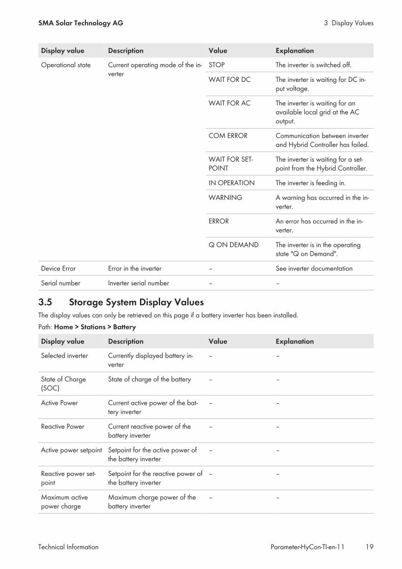
3.10 Display values for external interpolation pointsPath: Home > Visualizations > External setpoints
Display value Description Value Explanation
Ackn The SCADA system sends this signal to the Hy-brid Controller. This acknowledges warnings anderrors.
- -
OpCtrlCmd Control mode command requirement from SCADAsystem
- -
PwrAtSpnIn Setpoint for the delivery of active power by the hy-brid system specified by the SCADA system: If com-munication is intact, this value corresponds to thesetting in the SCADA system.
- -
PwrRtSpnIn Setpoint for the delivery of reactive power by thehybrid system specified by the SCADA system: Ifcommunication is intact, this value corresponds tothe setting in the SCADA system.
- -
PwrAtAprSpnt SCADA system setpoint for active power setpoint - -
PwrAtLimHi Upper active power limitation for the entire hybridsystem set by the SCADA system
- -
PwrAtLimLo Lower active power limitation for the entire hybridsystem set by the SCADA system
- -
PwrAtLimSale Active power limitation of all inverters for direct sell-ing set by the SCADA system
- -
PwrAtMpp MPP power estimation set by the SCADA system - -
PwrAtRateMax Maximum rate of change of active power set bythe SCADA system
- -
PwrRtRateMax Maximum rate of change of reactive power set bythe SCADA system
- -
PwrApLim Apparent power limitation set by the SCADA sys-tem
- -
PwrRtLimHi Upper active power limitation for the entire hybridsystem set by the SCADA system
- -
PwrRtLimLo Lower active power limitation for the entire hybridsystem set by the SCADA system
- -
CosPhiSpnt SCADA system setpoint for cos phi setpoint - -
VtgSpnt SCADA system setpoint for voltage setpoint - -
3.11 Display values for ripple control receivers and communication inaccordance with IEC 60807
Path: Home > Visualizations > IEC, RCR

3 Display ValuesSMA Solar Technology AG
Technical Information 27Parameter-HyCon-TI-en-11
Ripple control receiver (RCP - Ripple Control Receiver):
Display value Description Value Explanation
Active powerlimitation
Status of active power limitation Function not ac-tivated
Active power limitation isdisabled.
Function en-abled
Active power control is en-abled.
Communication in accordance with IEC 60870:
Display value Description Value Explanation
IEC 60870communicationstate
Status of communication connection in accordancewith IEV 60870
Disconnected The connection is inter-rupted.
Connected The connection is active.
3.12 Device InformationPath: Home > Visualizations > Device Information
Name line Description
HyCon serial number Indication of serial number
State of the applica-tion
Display of the state of application
MSys version Indication of the installed version of the operating system
CPU temperature Display of the processor temperature in the product
CAN bus load Display of the load of the CAN bus
CAN message bufferload
Display of the current capacity used in the CAN message store

4 System Settings SMA Solar Technology AG
Technical InformationParameter-HyCon-TI-en-1128
4 System Settings4.1 Parameters for the Utility GridThe system settings can only be changed in operating state STANDBY or ERROR. The operating state STANDBY canbe reached by stopping the system (see the user manual for Hybrid Controller).Path: Home > Wizard > Grid > General
Parameters Description Value Explanation Defaultvalue
Enable Determines whether the Hy-brid Controller should take theutility grid into account for controlof the hybrid system
Yes The Hybrid Controller takesthe utility grid into account.
No
No The Hybrid Controller takesnot the utility grid into ac-count.
Nominal activepower
Rated active power of utility grid 0 kW to 10000 kW – –
Short-circuit cur-rent capability
Short-circuit current capability ofthe utility grid
0 A to 10000 A – –
MCB feedbackvia
Defines the source of the feed-back signal from the MCB com-ponent in the control system
DI 8 Switching input DI 8 DI 8
COM External communicationnetwork
4 System SettingsSMA Solar Technology AG
Technical Information 29Parameter-HyCon-TI-en-11
Parameters Description Value Explanation Defaultvalue
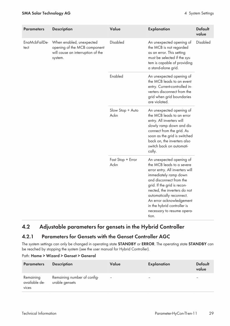
EnaMcbFailDe-tect
When enabled, unexpectedopening of the MCB componentwill cause an interruption of thesystem.
Disabled An unexpected opening ofthe MCB is not regardedas an error. This settingmust be selected if the sys-tem is capable of providinga stand-alone grid.
Disabled
Enabled An unexpected opening ofthe MCB leads to an evententry. Current-controlled in-verters disconnect from thegrid when grid boundariesare violated.
Slow Stop + AutoAckn
An unexpected opening ofthe MCB leads to an errorentry. All inverters willslowly ramp down and dis-connect from the grid. Assoon as the grid is switchedback on, the inverters alsoswitch back on automati-cally.
Fast Stop + ErrorAckn
An unexpected opening ofthe MCB leads to a severeerror entry. All inverters willimmediately ramp downand disconnect from thegrid. If the grid is recon-nected, the inverters do notautomatically reconnect.An error acknowledgementin the hybrid controller isnecessary to resume opera-tion.
4.2 Adjustable parameters for gensets in the Hybrid Controller
4.2.1 Parameters for Gensets with the Genset Controller AGCThe system settings can only be changed in operating state STANDBY or ERROR. The operating state STANDBY canbe reached by stopping the system (see the user manual for Hybrid Controller).Path: Home > Wizard > Genset > General
Parameters Description Value Explanation Defaultvalue
Remainingavailable de-vices
Remaining number of config-urable gensets
– – –

4 System Settings SMA Solar Technology AG
Technical InformationParameter-HyCon-TI-en-1130
Parameters Description Value Explanation Defaultvalue
Number of de-vices
Number of installed gensets 0 to 8 – 0
Generator In-terface Type
Type of genset interface DEIF AGC Genset Controllers of theAGC series (manufacturer:DEIF)
None
Path: Home > Wizard > Genset > Detail
Parameters Description Value Explanation Defaultvalue
Alias Genset / genset controller ID – – –
Enable this gen-erator
Determines whether the Hy-brid Controller should take thegenset into account for control ofthe hybrid system
Yes The Hybrid Controller takesthe genset into account.
No
No The Hybrid Controller takesthe genset not into account.
IP address IP address of the genset con-troller (not applicable with ahigher-level control system)
172.16.1.31 to172.16.1.38
Address range defined bythe Hybrid Controller forgensets
172.16.1.31
Unit-ID (Mod-bus/TCP)
Genset controller ID for the Mod-bus/TCP protocol
1 to 254 – 0
Rated activepower
Rated power of the genset 0 kW to 10000 kW – 0 kW
Apply changesto all devices
Enables transfer of the current set-tings for all gensets with GensetController DSE8610
Checkbox enabled Transfer of current settingsfor all gensets is enabled.
Disabled
Checkbox disabled Transfer of current settingsfor all gensets is disabled.
4.2.2 Parameters for Gensets with Genset Controller ComAp InteliGen NTC orComAp InteliSys NTC
Genset general configurationThe system settings can only be changed in operating state STANDBY or ERROR. The operating state STANDBY canbe reached by stopping the system (see the user manual for Hybrid Controller).Path: Home > Wizard > Genset > General
Parameters Description Value Explanation Defaultvalue
Remainingavailable de-vices
Remaining number of config-urable gensets
– – –
Number of de-vices
Number of installed gensets 0 to 8 – 0

4 System SettingsSMA Solar Technology AG
Technical Information 31Parameter-HyCon-TI-en-11
Parameters Description Value Explanation Defaultvalue
Genset inter-face type
Type of genset interface ComAp IG-/IS-NTC Genset Controller ComApInteliGen NTC or ComApInteliSys NTC with Mod-bus/TCP communication(manufacturer: ComAp)*
None
ComAp accesscode
Password for access to the gensetcontroller
0 to 65535 The maximum length of thepassword is 16 bits.
0
ComAp adminpassword
Administrator password for writeaccess to parameters of thegenset controller
0 to 65535 The maximum length of thepassword is 16 bits.
0
Genset setpointmechanism
Enables the writing of reservepower setpoints to the gensetcontroller system Configuring theMinimum Genset Load Threshold
Yes The setpoints for the reservepower is enabled.
No
No The setpoints for the reservepower is disabled.
Write start/stoprequest com-mand
Enables writing of the remotestart command to the gensets
Yes Function is enabled.* No
No Function is disabled.
* for settings on the genset controller Section 4.3.1, page 39Path: Home > Wizard > Genset > Detail
Parameters Description Value Explanation Defaultvalue
Alias Genset / genset controller ID – – –
Enable this gen-erator
Determines whether the Hy-brid Controller should take thegenset into account for control ofthe hybrid system
Yes The Hybrid Controller takesthe genset into account.
No
No The Hybrid Controller takesthe genset not into account.
IP address IP address of the genset con-troller (not applicable with ahigher-level control system)
172.16.1.31 to172.16.1.38
Address range defined bythe Hybrid Controller forgensets
172.16.1.31
Unit-ID (Mod-bus/ TCP)
Genset controller ID for the Mod-bus/TCP protocol
1 to 254 – 0
Nominal activepower
Nominal power of the genset 0 kW to 10000 kW – 0 kW
Short-circuit cur-rent capability
Short-circuit current capability ofthe genset
0 A to 10000 A This value is needed for anestimation of the availableand necessary short-circuitcurrent capability in theBAT_IOP.
0 A
4 System Settings SMA Solar Technology AG
Technical InformationParameter-HyCon-TI-en-1132
Parameters Description Value Explanation Defaultvalue
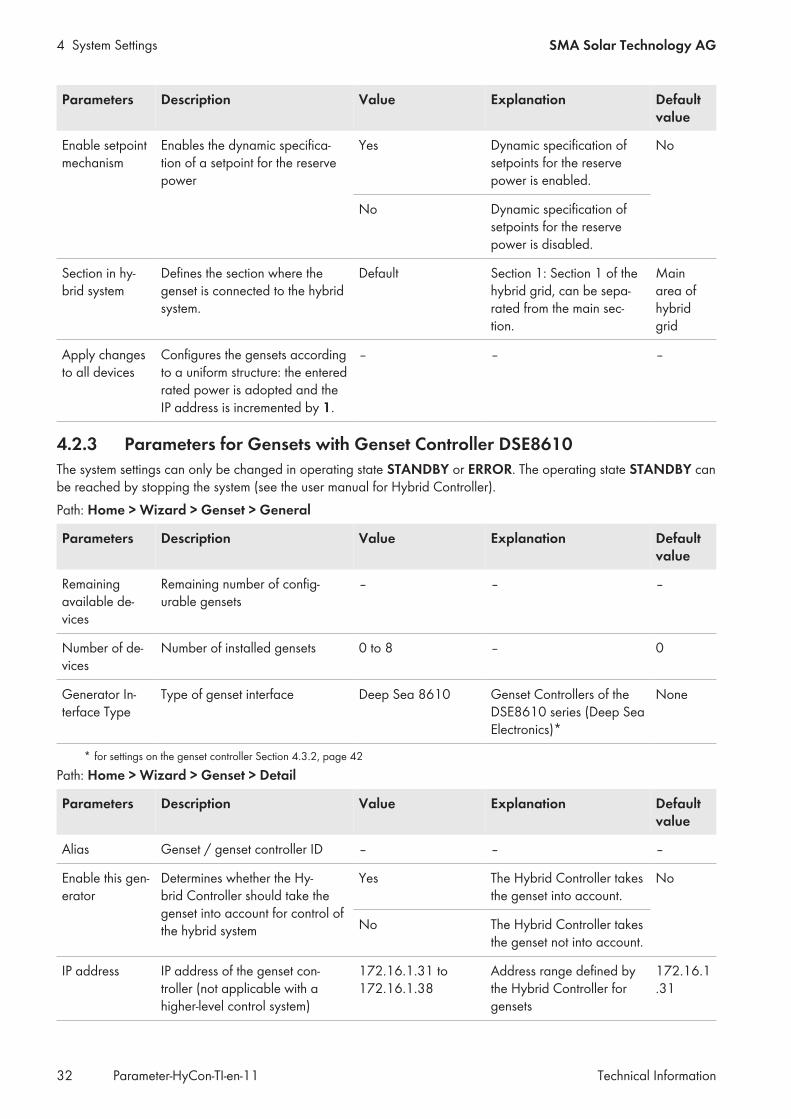
Enable setpointmechanism
Enables the dynamic specifica-tion of a setpoint for the reservepower
Yes Dynamic specification ofsetpoints for the reservepower is enabled.
No
No Dynamic specification ofsetpoints for the reservepower is disabled.
Section in hy-brid system
Defines the section where thegenset is connected to the hybridsystem.
Default Section 1: Section 1 of thehybrid grid, can be sepa-rated from the main sec-tion.
Mainarea ofhybridgrid
Apply changesto all devices
Configures the gensets accordingto a uniform structure: the enteredrated power is adopted and theIP address is incremented by 1.
– – –
4.2.3 Parameters for Gensets with Genset Controller DSE8610The system settings can only be changed in operating state STANDBY or ERROR. The operating state STANDBY canbe reached by stopping the system (see the user manual for Hybrid Controller).Path: Home > Wizard > Genset > General
Parameters Description Value Explanation Defaultvalue
Remainingavailable de-vices
Remaining number of config-urable gensets
– – –
Number of de-vices
Number of installed gensets 0 to 8 – 0
Generator In-terface Type
Type of genset interface Deep Sea 8610 Genset Controllers of theDSE8610 series (Deep SeaElectronics)*
None
* for settings on the genset controller Section 4.3.2, page 42Path: Home > Wizard > Genset > Detail
Parameters Description Value Explanation Defaultvalue
Alias Genset / genset controller ID – – –
Enable this gen-erator
Determines whether the Hy-brid Controller should take thegenset into account for control ofthe hybrid system
Yes The Hybrid Controller takesthe genset into account.
No
No The Hybrid Controller takesthe genset not into account.
IP address IP address of the genset con-troller (not applicable with ahigher-level control system)
172.16.1.31 to172.16.1.38
Address range defined bythe Hybrid Controller forgensets
172.16.1.31

4 System SettingsSMA Solar Technology AG
Technical Information 33Parameter-HyCon-TI-en-11
Parameters Description Value Explanation Defaultvalue
Unit-ID (Mod-bus/ TCP)
Genset controller ID for the Mod-bus/TCP protocol
1 to 254 – 0
Nominal activepower
Nominal power of the genset 0 kW to 10000 kW – 0 kW
Short-circuit cur-rent capability
Short-circuit current capability ofthe genset
0 A to 10000 A This value is needed for anestimation of the availableand necessary short-circuitcurrent capability in theBAT_IOP.
0 A
Section in hy-brid system
Defines the section where thegenset is connected to the hybridsystem.
Default Section 1: Section 1 of thehybrid grid, can be sepa-rated from the main sec-tion.
Mainarea ofhybridgrid
Apply changesto all devices
Enables transfer of the current set-tings for all gensets with GensetController DSE8610
Checkbox enabled Transfer of current settingsfor all gensets is enabled.
Disabled
Checkbox disabled Transfer of current settingsfor all gensets is disabled.
4.2.4 Parameters for gensets with genset controller easYgen-3000 via the CANnetwork
Path: Home > Wizard > Genset > GeneralThe system settings can only be changed in operating state STANDBY or ERROR. The operating state STANDBY canbe reached by stopping the system (see the user manual for Hybrid Controller).Path: Home > Wizard > Genset > General
Parameters Description Value Explanation Defaultvalue
Remainingavailable de-vices
Remaining number of config-urable gensets
– – –
Number of de-vices
Number of installed gensets 0 to 8 – 0
Genset inter-face type
Type of genset interface easYgen 3000 CAN Genset Controller easY-gen-3000 with CAN com-munication (manufacturer:Woodward)*
None
CAN#1 pass-word
Password for write access to thegenset controller
0 to 9999 For setting the password,refer to manufacturer docu-mentation
–

4 System Settings SMA Solar Technology AG
Technical InformationParameter-HyCon-TI-en-1134
Parameters Description Value Explanation Defaultvalue
Genset setpointmechanism
Enables the specification of set-points for the reserve power Con-figuring the Minimum GensetLoad Threshold
Checkbox enabled The specification of set-points for the reservepower is enabled
Disabled
Checkbox disabled The specification of set-points for the reservepower is disabled.
Write start/stoprequest com-mand
Enables writing of the remotestart command to the gensets
Checkbox enabled Function is enabled.* Disabled
Checkbox disabled Function is disabled.
* for settings on the genset controller Section 4.3.3, page 42Path: Home > Wizard > Genset > Detail
Parameters Description Value Explanation Defaultvalue
Alias Genset / genset controller ID – – –
Enable thisgenset
Determines whether the Hy-brid Controller should take thegenset into account for control ofthe hybrid system
Yes The Hybrid Controller takesthe genset into account.
No
No The Hybrid Controller takesthe genset not into account.
PDO-ID Proto-col 6000
Genset controller ID for the proto-col 6000 (load distribution mes-sage)
0 to 2047 For more information on thegenset controller, see themanufacturer documenta-tion
1280
PDO-ID Proto-col 5003
Genset controller ID for the dataprotocol 5003 (basic visualiza-tion)
0 to 2047 385
Service DataObject ID
Genset controller ID for communi-cating via Service Data Objects(SDO)
0 to 2047 1537
Timeout forPDO-ID Proto-col 6000
Timeout for transfer according toprotocol 6000
20 ms to 60000 ms The setpoint for the timeoutmust be higher than the cy-cle time configured in thegenset controller (for moreinformation on the gensetcontroller, see the manufac-turer documentation).
250 ms
Timeout forPDO-ID Proto-col 5003
Timeout for transfer according todata protocol 5003
20 ms to 60000 ms 250 ms
Timeout for Ser-vice Data Ob-ject ID
Timeout for communication viaService Data Objects
20 ms to 60000 ms 500 ms
Nominal activepower
Nominal power of the genset 0 kW to 10000 kW – 0 kW

4 System SettingsSMA Solar Technology AG
Technical Information 35Parameter-HyCon-TI-en-11
Parameters Description Value Explanation Defaultvalue
Short-circuit cur-rent capability
Short-circuit current capability ofthe genset
0 A to 10000 A This value is needed for anestimation of the availableand necessary short-circuitcurrent capability in theBAT_IOP.
0 A
Section in hy-brid system
Defines the section where thegenset is connected to the hybridsystem.
Default Section 1: Section 1 of thehybrid grid, can be sepa-rated from the main sec-tion.
Mainarea ofhybridgrid
Apply changesto all devices
Enables the transfer of current set-tings for all gensets
Checkbox enabled Transfer of current settingsfor all gensets is enabled.
Disabled
Checkbox disabled Transfer of current settingsfor all gensets is disabled.
4.2.5 Parameters for Gensets with Genset Controller easYgen-3000 via theESENET Gateway
The system settings can only be changed in operating state STANDBY or ERROR. The operating state STANDBY canbe reached by stopping the system (see the user manual for Hybrid Controller).Path: Home > Wizard > Genset > General
Parameters Description Value Explanation Defaultvalue
Remainingavailable de-vices
Remaining number of con-figurable gensets
– – –
Number of de-vices
Number of installedgensets
0 to 8 – 0
Genset inter-face type
Type of genset interface easYgen 3000 ES-ENET-Gateway
Genset Controller easYgen-3000with Modbus/TCP communica-tion via Ethernet gateway ES-ENET (manufacturer: Wood-ward)*
None
CAN#1 pass-word
Password for write accessto the genset controller
0 to 9999 For setting the password, refer tomanufacturer documentation
0
Genset setpointmechanism
Enables the writing of re-serve power setpoints tothe genset controller systemConfiguring the MinimumGenset Load Threshold
Yes The setpoints for the reservepower is enabled.
No
No The setpoints for the reservepower is disabled.

4 System Settings SMA Solar Technology AG
Technical InformationParameter-HyCon-TI-en-1136
Parameters Description Value Explanation Defaultvalue
Parameter com-pare mecha-nism
Compares the rated powervalues of the gensets set inthe Hybrid Controller withthose of the genset con-trollers
Checkbox enabled Comparison of genset ratedpower is enabled
Disabled
Checkbox disabled Comparison of genset ratedpower is disabled.
* for settings on the genset controller Section 4.3.3, page 42Path: Home > Wizard > Genset > Detail
Parameters Description Value Explanation Defaultvalue
Alias Genset / genset controller ID – – –
Enable thisgenset
Determines whether the Hy-brid Controller should take thegenset into account for control ofthe hybrid system
Yes The Hybrid Controller takesthe genset into account.
No
No The Hybrid Controller takesthe genset not into account.
ESENET-Gate-way IP address
IP address of the ESENET gate-way (not applicable with ahigher-level control system)
172.16.3.1 to172.16.3.70
Address range defined bythe Hybrid Controller forgensets
172.16.3.1
Unit-ID (Mod-bus/TCP)
Genset controller ID for the Mod-bus/TCP protocol
1 to 254 – –
Nominal activepower
Nominal power of the genset 0 kW to 10000 kW – 0 kW
Short-circuit cur-rent capability
Short-circuit current capability ofthe genset
0 A to 10000 A This value is needed for anestimation of the availableand necessary short-circuitcurrent capability in theBAT_IOP.
0 A
Section in hy-brid system
Defines the section where thegenset is connected to the hybridsystem.
Default Section 1: Section 1 of thehybrid grid, can be sepa-rated from the main sec-tion.
Mainarea ofhybridgrid
Apply changesto all devices
Enables the transfer of current set-tings for all gensets
Checkbox enabled Transfer of current settingsfor all gensets is enabled.
Disabled
Checkbox disabled Transfer of current settingsfor all gensets is disabled.
4.2.6 Parameters for Gensets with the Genset Controller GENSYS 2.0The system settings can only be changed in operating state STANDBY or ERROR. The operating state STANDBY canbe reached by stopping the system (see the user manual for Hybrid Controller).

4 System SettingsSMA Solar Technology AG
Technical Information 37Parameter-HyCon-TI-en-11
Path: Home > Wizard > Genset > General
Parameters Description Value Explanation Defaultvalue
Remainingavailable de-vices
Remaining number of con-figurable gensets
– – -
Number of de-vices
Number of installedgensets
0 to 8 – 0
Genset inter-face type
Type of genset interface Generic Genset Genset Controller GENSYS 2.0(Manufacturer: CRE Technol-ogy)*
None
Activate spin-ning reservesetpoint
Enables the writing of thedynamic setpoints for thegenset reserve power.
Checkbox enabled Setting of the dynamic setpointsfor the genset reserve power isenabled.
Disabled
Checkbox disabled Setting of the dynamic setpointsfor the genset reserve power isdisabled.
Write start/stoprequest com-mand
Enables writing of the re-mote start command to thegensets
Checkbox enabled Writing of the remote start com-mand is enabled.
Disabled
Checkbox disabled Writing of the remote start com-mand is disabled.
* for settings on the genset controller Section 4.3.4, page 44Path: Home > Wizard > Genset > Detail
Parameters Description Value Explanation Defaultvalue
Alias Genset / genset controller ID – – –
Enable thisgenset
Determines whether the Hy-brid Controller should take thegenset into account for control ofthe hybrid system
Yes The Hybrid Controller takesthe genset into account.
No
No The Hybrid Controller takesthe genset not into account.
IP address IP address of the genset con-troller
172.16.3.1 to172.16.3.70
Address range defined bythe Hybrid Controller forgensets
172.16.3.1
User config.state
Status of the imported user con-figuration
User config. success-fully initalized
The configuration enteredvia the user interface hasbeen initialized.
-
Default config initial-ized
The standard configurationhas been initialized.
Nominal activepower
Nominal power of the genset 0 kW to 10000 kW – 0 kW

4 System Settings SMA Solar Technology AG
Technical InformationParameter-HyCon-TI-en-1138
Parameters Description Value Explanation Defaultvalue
Short-circuit cur-rent capability
Short-circuit current capability ofthe genset
0 A to 10000 A This value is needed for anestimation of the availableand necessary short-circuitcurrent capability in theBAT_IOP.
12 A
Section in hy-brid system
Defines the section where thegenset is connected to the hybridsystem.
Default Section 1: Section 1 of thehybrid grid, can be sepa-rated from the main sec-tion.
Mainarea ofhybridgrid
Apply changesto all devices
Configures the gensets according to a uniform structure: the entered rated power is adopted andthe IP address is incremented by 1.
4.2.7 Parameters for Gensets without the Genset ControllerThe system settings can only be changed in operating state STANDBY or ERROR. The operating state STANDBY canbe reached by stopping the system (see the user manual for Hybrid Controller).Path: Home > Wizard > Genset > General
Parameters Description Value Explanation Defaultvalue
Remainingavailable de-vices
Remaining number of config-urable gensets
– – –
Number of de-vices
Number of installed gensets 0 to 8 – 0
Genset inter-face type
Type of genset interface None The genset is monitored viathe current and voltagemeasurement of the Hy-brid Controller. No gensetcontroller is used.
None
Path: Home > Wizard > Genset > Detail
Parameters Description Value Explanation Defaultvalue
Alias Name for identification of genset – – –
Enable this gen-erator
Determines whether the Hy-brid Controller should take thegenset into account for control ofthe hybrid system
Yes The Hybrid Controller takesthe genset into account.
No
No The Hybrid Controller takesthe genset not into account.
Nominal activepower
Nominal power of the genset 0 kW to 10000 kW – 0 kW

4 System SettingsSMA Solar Technology AG
Technical Information 39Parameter-HyCon-TI-en-11
Parameters Description Value Explanation Defaultvalue
Short-circuit cur-rent capability
Short-circuit current capability ofthe genset
0 A to 10000 A This value is needed for anestimation of the availableand necessary short-circuitcurrent capability in theBAT_IOP.
0 A
Section in hy-brid system
Defines the section where thegenset is connected to the hybridsystem.
Default Section 1: Section 1 of thehybrid grid, can be sepa-rated from the main sec-tion.
Mainarea ofhybridgrid
Apply changesto all devices
Enables the transfer of current set-tings for all gensets
Checkbox enabled Transfer of current settingsfor all gensets is enabled.
Disabled
Checkbox disabled Transfer of current settingsfor all gensets is disabled.
4.3 Settings on the Genset ControllersThe following sections describe which settings you have to make on the genset controllers (for the implementation ofthese settings, see the genset controller documentarian).
4.3.1 Settings on ComAp InteliGen NTC or ComAp InteliSys NTC GensetControllers
You can use the following settings for the ComAp InteliMonitor configuration software.
Observing manufacturer documentation of genset controllerWhen using a genset controller with the Hybrid Controller, the following settings must be made on the gensetcontroller. At the same time, the specifications stated in the manufacturer documentation must be observed at alltimes (see the genset controller documentation).
IP settingsFor each genset controller of the ComAp InteliGen NTC or ComAp InteliSys NTC series, the following IP settings mustbe made on the genset controller.
IP setting Specified value
IP Address 172.16.1.31 to 172.16.1.38*
Subnet mask 255.255.0.0
Standard gateway 172.16.1.11
* Only one IP address must be assigned to each genset controller.
Assignment of Modbus registersThe Modbus registers from the tab Contr Modbus needed for the use with the Hybrid Controller must be assigned tothe following Modbus registers from the tab User Modbus. The assignment of the Modbus registers must be set in thegenset controller.

4 System Settings SMA Solar Technology AG
Technical InformationParameter-HyCon-TI-en-1140
In order to facilitate the assignment of the Modbus registers, the configuration software ComAp GenConfig can beused.
User Modbus tab Contr Modbus tab
Register number Register number Register name Explanation
42873 40003 BIN Binary inputs
42874 40264 Act power Active power
42875 40269 React power Reactive power
42876 40274 Appar power Apparent power
42877 40261 Pwr factor Power factor
42878 40256 Gen freq Generator frequency
42879 43587 Run hours (1/2) Operating hours
42880 43588 Run hours (2/2)
42881 43009 Nomin power Rated power
42882 43595 kWhours (1/2) Meter reading in kWh
42883 43596 kWhours (2/2)
42884 40168 ControllerMode Operating mode
42885 40349 Engine Prio Priority of the gensets
42886 40132 LogBout 3 Logical binary outputs
42887 40133 LogBout 4
42888 40253 Gen V L1-L2 Generator voltage between L1 and L2
42889 40254 Gen V L2-L3 Generator voltage between L2 and L3
42890 40255 Gen V L3-L1 Generator voltage between L3 and L1
42891 40249 Gen V L1-N Generator voltage between L1 and N
42892 40250 Gen V L2-N Generator voltage between L2 and N
42893 40251 Gen V L3-N Generator voltage between L3 and N
42894 40258 Gen curr L1 Generator current L1
42895 40259 Gen curr L2 Generator current L2
42896 40260 Gen curr L3 Generator current L3
Passwords
Password for access to the genset controller by the Hybrid ControllerThe Hybrid Controller and communication processor of the IB-COM of a genset controller of the ComAp InteliGenNTC or ComAp InteliSys NTC series are communicating with each other via Modbus/TCP. For this communicationprocess, a shared password is necessary. The following requirements must be fulfilled when choosing a sharedpassword:

4 System SettingsSMA Solar Technology AG
Technical Information 41Parameter-HyCon-TI-en-11
• The password must not exceed a maximum length of 16 bit.• The password must be preset in the genset controller.• The password settings must be adopted for the parameter ComAp access code of the Hybrid Controller.
Administrator password for write access to parameters of the genset controller by the Hybrid ControllerAn administrator password is necessary for write access to parameters of the genset controller by theHybrid Controller. The following requirements must be fulfilled when choosing an administrator password:
• The administrator password must not exceed a maximum length of 16 bit.• The administrator password must be preset in the genset controller.• The administrator password settings must be adopted for the parameter ComAp admin password of the
Hybrid Controller.
Assignment of the input signal ExtValue1 to the internal signal DynSpinResReqFor the remote start request by the Hybrid Controller and for the dynamic reserve power request of the PV power plant,genset controllers of the ComAp InteliGen NTC or ComAp InteliSys NTC series must be equipped with the ComApIGS-NT-Hybrid firmware. In addition, the requirements from the following table must be met.
Remote start request via Hybrid Controller The input signal ExtValue2 can be transferred to the in-ternal signal Sys start/stop. System-specific require-ments must be taken into account. This signal transfermust be set in the genset controller.
Dynamic reserve power requirement of PV power plant The input signal ExtValue1 must be transferred to the in-ternal signal DynSpinResReq. This signal transfer mustbe set in the genset controller. Depending on assembly ofthe hybrid system, the following variants must be se-lected:
• Signal transfer from Hybrid Controller to all gensetcontrollersThe Hybrid Controller transfers the ExtValue1signal to all genset controllers in the hybrid system.This variant is recommended since, in the event of agenset controller failure, all other genset controllersremain unaffected. The transmission of theExtValue1 input signal to the internalDynSpinResReq signal must be set on every gensetcontroller.
• Signal transfer from Hybrid Controller to 1 gensetcontrollerThe Hybrid Controller transfers the ExtValue1signal to 1 genset controller in the hybrid system.With this genset controller, the transmission of theExtValue1 input signal to the internalDynSpinResReq signal and the forwarding of theinternal DynSpinResReq signal to all other gensetcontrollers must be set.

4 System Settings SMA Solar Technology AG
Technical InformationParameter-HyCon-TI-en-1142
Function "Password Break Protection"For write access to parameters of the genset controller by the Hybrid Controller, the "Password Break Protection"function must be disabled.
4.3.2 Settings on DSE8610 Genset Controllers or DSE8610 MKIIObserving manufacturer documentation of genset controllerWhen using a genset controller with the Hybrid Controller, the following settings must be made on the gensetcontroller. At the same time, the specifications stated in the manufacturer documentation must be observed at alltimes (see the genset controller documentation).
In the user interface of the genset controller, the following register settings must be selected in the directory Advance >Configurable Gencomm Pages > Page 166.
Register Value
0-1 Generator Average Power Factor
2-3 Page = 3, Register = 4, Size = 16 bit
4-5 Generator Positive kWh
6-7 Generator Available
8-9 Generator Current L1
10-11 Generator Current L2
12-13 Generator Current L3
14-15 Engine Run Time
16-17 Page = 137, Register = 32, Size = 16 bit
18-19 Generator Total VA
20-21 Generator Total Power
22-23 Generator Total VAr
24-25 Generator Volts (L1-L2)
26-27 Generator Volts (L2-L3)
28-29 Generator Volts (L3-L1)
30-31 Generator% Full Power (Load Sharing)
32-33 Generator Total Lead/Lag
34-35 Page = 3, Register = 6, Size = 16 bit
4.3.3 Settings on easYgen 3000 Genset ControllersObserving manufacturer documentation of genset controllerWhen using a genset controller with the Hybrid Controller, the following settings must be made on the gensetcontroller. At the same time, the specifications stated in the manufacturer documentation must be observed at alltimes (see the genset controller documentation).
4 System SettingsSMA Solar Technology AG
Technical Information 43Parameter-HyCon-TI-en-11
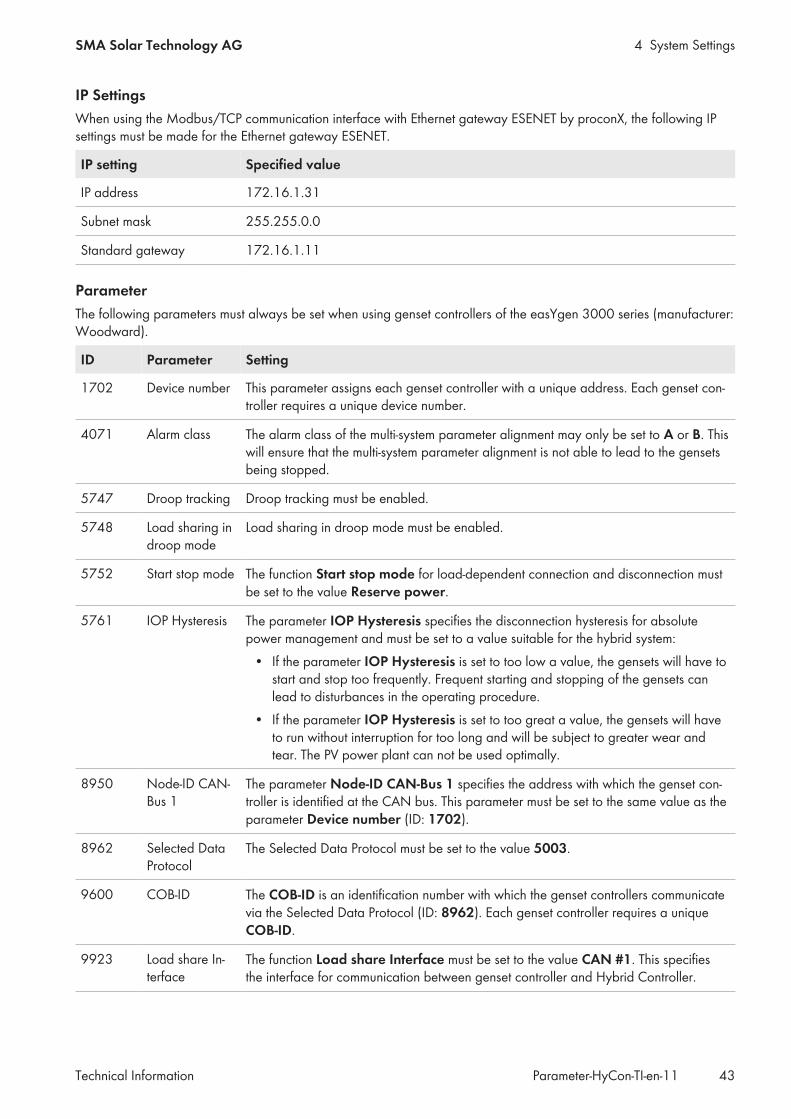
IP SettingsWhen using the Modbus/TCP communication interface with Ethernet gateway ESENET by proconX, the following IPsettings must be made for the Ethernet gateway ESENET.
IP setting Specified value
IP address 172.16.1.31
Subnet mask 255.255.0.0
Standard gateway 172.16.1.11
ParameterThe following parameters must always be set when using genset controllers of the easYgen 3000 series (manufacturer:Woodward).
ID Parameter Setting
1702 Device number This parameter assigns each genset controller with a unique address. Each genset con-troller requires a unique device number.
4071 Alarm class The alarm class of the multi-system parameter alignment may only be set to A or B. Thiswill ensure that the multi-system parameter alignment is not able to lead to the gensetsbeing stopped.
5747 Droop tracking Droop tracking must be enabled.
5748 Load sharing indroop mode
Load sharing in droop mode must be enabled.
5752 Start stop mode The function Start stop mode for load-dependent connection and disconnection mustbe set to the value Reserve power.
5761 IOP Hysteresis The parameter IOP Hysteresis specifies the disconnection hysteresis for absolutepower management and must be set to a value suitable for the hybrid system:
• If the parameter IOP Hysteresis is set to too low a value, the gensets will have tostart and stop too frequently. Frequent starting and stopping of the gensets canlead to disturbances in the operating procedure.
• If the parameter IOP Hysteresis is set to too great a value, the gensets will haveto run without interruption for too long and will be subject to greater wear andtear. The PV power plant can not be used optimally.
8950 Node-ID CAN-Bus 1
The parameter Node-ID CAN-Bus 1 specifies the address with which the genset con-troller is identified at the CAN bus. This parameter must be set to the same value as theparameter Device number (ID: 1702).
8962 Selected DataProtocol
The Selected Data Protocol must be set to the value 5003.
9600 COB-ID The COB-ID is an identification number with which the genset controllers communicatevia the Selected Data Protocol (ID: 8962). Each genset controller requires a uniqueCOB-ID.
9923 Load share In-terface
The function Load share Interface must be set to the value CAN #1. This specifiesthe interface for communication between genset controller and Hybrid Controller.

4 System Settings SMA Solar Technology AG
Technical InformationParameter-HyCon-TI-en-1144
ID Parameter Setting
12120 Start req. inAUTO
Only if the optional function of the Hybrid Controller "Dynamic shutdown of thegensets" is used, the following setting must be made:The function Start. req. in AUTO and the input variable 04.13 Remote start must beactivated in the genset controller and connected via an AND operation.
12510 Operat. modeAUTO
The Operat. mode AUTO must be activated.
12930 Load dep. On/off
The function Load dep. on/off. for the load-dependent connection and disconnectionmust be activated.
33040 2. Node ID If a genset controller of the Woodward easYgen 3000 series is connected to the Hy-brid Controller via a CAN communication interface, and the Ethernet gateway ESENETis set in parallel, e.g. for an additional monitoring function, then so-called Ser-vice Data Objects (server SDOs) must be configured in the genset controller. Here, theidentification numbers of the server SDOs 2. Node ID must be set to values from33 to 65.
4.3.4 Settings on the Genset Controllers GENSYS 2.0Observing manufacturer documentation of genset controllerWhen using a genset controller with the Hybrid Controller, the following settings must be made on the gensetcontroller. At the same time, the specifications stated in the manufacturer documentation must be observed at alltimes (see the genset controller documentation).
IP SettingsWhen using the Modbus/TCP communication interface with Ethernet gateway ESENET by proconX, the following IPsettings must be made for the Ethernet gateway ESENET.
IP setting Specified value
IP address 172.16.1.31
Subnet mask 255.255.0.0
Standard gateway 172.16.1.11
CompatibilityGENSYS 2.0 genset controllers with firmware version 4.77e2 and from firmware version 5.05 are compatible for usewith the Hybrid Controller.
Modbus interfaceThe Modbus interface must be set to Port 502 and enabled.
Specific settings for the Hybrid Controller in the configuration fileGENSYS 2.0 genset controllers are include a configuration file that enables an application-specific modification of theparameter settings. This configuration file includes a number of settings in terms of Hybrid Controller operation in theModBus Mapping CRE TECHNOLOGY<>SMA section.If the settings for Hybrid Controller operation is modified, the genset controller and the Hybrid Controller may not becompatible anymore. Therefore, these settings may only be modified in cooperation with and with the express consentof SMA Solar Technology AG.

4 System SettingsSMA Solar Technology AG
Technical Information 45Parameter-HyCon-TI-en-11
4.4 Parameters for the PV Power PlantThe system settings can only be changed in operating state STANDBY or ERROR. The operating state STANDBY canbe reached by stopping the system (see the user manual for Hybrid Controller).
PV general configuration - Buttons
Button Parameter
Add new item Add a device type for the PV inverter
Remove item Remove a device type for the PV inverter
Path: Home > Wizard > PV > General
Parameters Description Value Explanation
Remaining availabledevices
Remaining number of con-figurable inverters
– –
Type of inverter Inverter device type Sunny Tripower Type of an inverter of the Sunny Tripower se-ries: STP 20000TL-30 / STP 25000TL-30 /STP 15000TLEE-10 / STP 20000TLEE-10
Sunny TripowerTL-60
Type of an inverter of the Sunny Tripower se-ries: STP 60-10
Sunny CentralCP
Type of an inverter of the Sunny Cen-tral CP XT series
Sunny Central2200/2500
Type of a Sunny Central XXXX(-EV) inverter of
Number of inverters Number of installed invert-ers of the same device type
0 to 64 –
Path: Home > Wizard > PV > Detail
Parameter/checkbox
Description Value Explanation Defaultvalue
Alias Type label for identifying the in-verter
– – –
Enable this in-verter
Determines whether the Hy-brid Controller should take the in-verter into account for control ofthe hybrid system
Yes The Hybrid Controller takesthe inverter into account.
No
No The Hybrid Controller takesthe inverter not into ac-count.
IP address IP address of the inverter 172.16.200.1 to172.16.200.64
Address range defined bythe Hybrid Controller for in-verters
–
Protocol Communication protocol used bythe inverter
Defined by Type ofinverter
See inverter documentation Definedby Typeof in-verterDifferent communica-
tion protocol

4 System Settings SMA Solar Technology AG
Technical InformationParameter-HyCon-TI-en-1146
Parameter/checkbox
Description Value Explanation Defaultvalue
Modbus UnitID
Inverter ID for the Modbus/TCPprotocol
126 to 167 See inverter documentation –
EnableQ on demand
The Hybrid Controller uses the in-verter's "Q on Demand" function.
Yes "Q on Demand" is beingused.
No
No "Q on Demand" is not be-ing used.
Rated DCPower
Rated DC input power of the in-verterEach PV inverter may be con-nected to as many PV modules asthe maximum DC power and themaximum input voltage of the PVinverter allow. If less modules areconnected, the correspondingDC input power must be storedvia this parameter.
0 kW to 10000 kW – 0 kW
Short circuit cur-rent capability
The inverter's capability to outputshort-circuit current
0 A to 10000 A – –
Apply changesto all devices
Selection of the configurationscheme
Enabled Configures all inverters ac-cording to the samescheme*
–
Disabled Only configures the se-lected inverter
* The entered rated power is adopted and the IP address is incremented by 1.
4.5 Parameters for the Storage SystemThe parameters can only be set on this page if a battery inverter has been installed.The system settings can only be changed in operating state STANDBY or ERROR. The operating state STANDBY canbe reached by stopping the system (see the user manual for Hybrid Controller).Path: Home > Wizard > Battery > General
Parameters Description Value
Remaining available de-vices
Remaining number of configurable battery inverters –
Quantity of battery con-trollers
Number of installed battery inverters of the same device type 0 to 16
Path: Home > Wizard > Battery > Detail
Parameter/checkbox
Description Value Explanation Defaultvalue
Alias Type label for identifying the in-verter
– – –

4 System SettingsSMA Solar Technology AG
Technical Information 47Parameter-HyCon-TI-en-11
Parameter/checkbox
Description Value Explanation Defaultvalue
Enable this in-verter
Determines whether the Hy-brid Controller should take the in-verter into account for control ofthe hybrid system
Yes The Hybrid Controller takesthe inverter into account.
No
No The Hybrid Controller takesthe inverter not into ac-count.
IP address IP address of the inverter 172.16.200.1 to172.16.200.64
Address range defined bythe Hybrid Controller for in-verters
–
Protocol Communication protocol used bythe inverter
Defined by Type ofinverter
See inverter documentation Definedby Typeof in-verterDifferent communica-
tion protocol
Short circuit cur-rent capability
The inverter's capability to outputshort-circuit current
0 A to 10000 A – –
Rated activepower
Rated active power of the in-verter
0 kW to 5000 kW – 2000 kW
Upper SOC op-erating limit
Upper SOC operating limit 0% to 100% – 100 %
Lower SOC op-erating limit
Lower SOC operating limit 0% to 100% – 0 %
Apply changesto all devices
Selection of the configurationscheme
Enabled Configures all inverters ac-cording to the samescheme*
–
Disabled Only configures the se-lected inverter
* The entered rated power is adopted and the IP address is incremented by 1.
4.6 Settings on the Measurement Devices
4.6.1 General Settings on Measurement DevicesThe system settings can only be changed in operating state STANDBY or ERROR. The operating state STANDBY canbe reached by stopping the system (see the user manual for Hybrid Controller).

4 System Settings SMA Solar Technology AG
Technical InformationParameter-HyCon-TI-en-1148
Path: Home > Wizard > Measurements > General
Display group Parameter Description Value Explanation Default value
Internal measure-ment devices
Remaining availabledevices
Remaining number ofconfigurable mea-surement devices
– – –
Number of devices Number of measure-ment devices installed
0 to 6 – 0
Frequency Rated frequency 50 Hz – 50 Hz
60 Hz –
Reset energy coun-ters
Reset the energy meters of all internal measurement modules. It is advis-able to only use the Reset energy counters function during commission-ing.
External measure-ment devices
Remaining availabledevices
Remaining number ofconfigurable mea-surement devices
0 to 32 – –
Type of Measure-ment device
Measurement devicetype
DAQ-11 Data AcquisitionModule
DAQ-11
Number of devices Number of measure-ment devices installed
0 to 32 – 0
4.6.2 Detailed Settings on Measurement Devices for Internal MeasurementModules of the Hybrid Controller
The system settings can only be changed in operating state STANDBY or ERROR. The operating state STANDBY canbe reached by stopping the system (see the user manual for Hybrid Controller).Path: Home > Wizard > Measurements > Detail
Parameters Description Value Explanation Default value
Alias Name for identification ofmeasurement devices
– – –
Enable this device Determines whether the Hy-brid Controller should takethe measuring device intoaccount for control of thehybrid system
Yes The Hybrid Controller takesthe measuring device intoaccount.
No
No The Hybrid Controller takesnot the measuring deviceinto account.

4 System SettingsSMA Solar Technology AG
Technical Information 49Parameter-HyCon-TI-en-11
Parameters Description Value Explanation Default value
Data source priority Use of the measured valuesfrom the Hybrid Controllerin the event of a communi-cation connection failure
Single source Connection to the devicecarrying out the measure-ments is disabled. Only themeasured values from theHybrid Controller are used.
–
Second source Connection to the devicecarrying out the measure-ments is enabled. The val-ues communicated by thedevice have priority. If com-munication fails, the mea-sured values from the Hy-brid Controller are used.
Measurementpriority
Connection to the devicecarrying out the measure-ments is enabled. The val-ues measured by the Hy-brid Controller have prior-ity. In case of measurementfailure, the values communi-cated by the device areused.
Device type Type of measurement mod-ule
GM260 – –
GMP232x –
Grid type Type of grid used for cur-rent and voltage measure-ment
3PH-3L Three-conductor utility gridwith three line conductors
–
3PH-4L Four-conductor utility gridwith three line conductorsand one neutral conductor
Ratio of potentialtransducer
Transformation ratio forvoltage measurement
The requirements of the measurement inputs must be compliedwith (see installation manual of the product).
Ratio of current trans-ducer
Transformation ratio for cur-rent measurement
The requirements of the measurement inputs must be compliedwith (see installation manual of the product).
Assign measurementpoints
Overview of the enableddevices, e.g. PV inverters
Devices can be enabled or disabled for the selected measure-ment device via the button [Show devices] (see user manualof Hybrid Controller).
Feeder number Current measurement num-ber (see product installa-tion manual)
1 to 6 – –
4.6.3 Detailed Settings on Measurement Devices for Data Acquisition ModulesThe parameters can only be set on this page if a Data Acquisition Module has been installed.The system settings can only be changed in operating state STANDBY or ERROR. The operating state STANDBY canbe reached by stopping the system (see the user manual for Hybrid Controller).
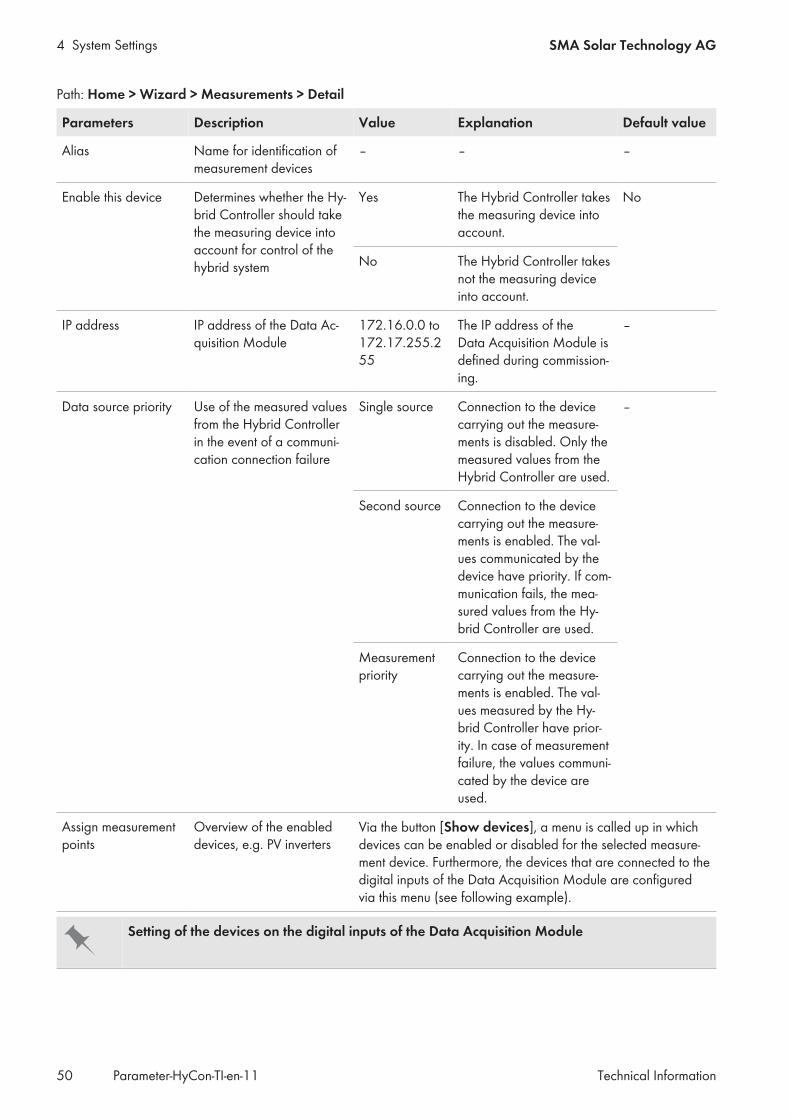
4 System Settings SMA Solar Technology AG
Technical InformationParameter-HyCon-TI-en-1150
Path: Home > Wizard > Measurements > Detail
Parameters Description Value Explanation Default value
Alias Name for identification ofmeasurement devices
– – –
Enable this device Determines whether the Hy-brid Controller should takethe measuring device intoaccount for control of thehybrid system
Yes The Hybrid Controller takesthe measuring device intoaccount.
No
No The Hybrid Controller takesnot the measuring deviceinto account.
IP address IP address of the Data Ac-quisition Module
172.16.0.0 to172.17.255.255
The IP address of theData Acquisition Module isdefined during commission-ing.
–
Data source priority Use of the measured valuesfrom the Hybrid Controllerin the event of a communi-cation connection failure
Single source Connection to the devicecarrying out the measure-ments is disabled. Only themeasured values from theHybrid Controller are used.
–
Second source Connection to the devicecarrying out the measure-ments is enabled. The val-ues communicated by thedevice have priority. If com-munication fails, the mea-sured values from the Hy-brid Controller are used.
Measurementpriority
Connection to the devicecarrying out the measure-ments is enabled. The val-ues measured by the Hy-brid Controller have prior-ity. In case of measurementfailure, the values communi-cated by the device areused.
Assign measurementpoints
Overview of the enableddevices, e.g. PV inverters
Via the button [Show devices], a menu is called up in whichdevices can be enabled or disabled for the selected measure-ment device. Furthermore, the devices that are connected to thedigital inputs of the Data Acquisition Module are configuredvia this menu (see following example).
Setting of the devices on the digital inputs of the Data Acquisition Module

4 System SettingsSMA Solar Technology AG
Technical Information 51Parameter-HyCon-TI-en-11
If the genset 1 is connected to digital input DI 1 on the Data Acquisition Module and the utility grid is connected todigital input DI 2, then the settings on the Hybrid Controller are correct in this example.If the utility grid is connected to digital input DI 1 on the Data Acquisition Module and the genset 1 is connected todigital input DI 2, then the settings on the Hybrid Controller are incorrect in this example. Incorrectly configureddevices must be disabled and re-enabled with the correct settings.
4.7 Settings on the Temperature and Irradiation SensorsThe system settings can only be changed in operating state STANDBY or ERROR. The operating state STANDBY canbe reached by stopping the system (see the user manual for Hybrid Controller).Path: Home > Wizard > Meteorologic > General
Parameters Description Value Explanation Defaultvalue
Remaining availabledevices
Remaining number of config-urable temperature and irradia-tion sensors
– – –
Number of devices Number of temperature and irra-diation sensors installed
0 to 6 – 0
Path: Home > Wizard > Meteorologic > Detail
Parameters Description Value Explanation Defaultvalue
Alias Name for identifying the sensor – – –
Enable device Determines whether the Hy-brid Controller should take thesensor into account for control ofthe hybrid system
Yes The Hybrid Controller takes thesensor into account.
No
No The Hybrid Controller takes thesensor not into account.

4 System Settings SMA Solar Technology AG
Technical InformationParameter-HyCon-TI-en-1152
Parameters Description Value Explanation Defaultvalue
Device type Type of temperature and irradia-tion sensors
SMA Me-teo Sta-tion
Interface to the SMA Cluster Con-troller or SMA Inverter Manager
SMA Me-teo Sta-tion
SunspecMini MetModel
Communication interface speci-fied according to SunSpec Mod-bus
SMADataManager
Interface to SMA Data ManagerM / SMA Data Manager L
Genericsky im-ager
Generic interface for a sky im-ager
SMA Me-teo Sta-tion Mod-bus TCP
Communication interface speci-fied according to Modbus TCP
Forcasting with skyimager
Forecasting with sky imager Yes Data from sky imager is takeninto account during PV genera-tion forecasting.
No
No Data from sky imager is not takeninto account during PV genera-tion forecasting.
IP address IP address of the sensor 172.16.xxx.81 to172.16.xxx.89*
Address range defined by theHybrid Controller for different de-vices (e.g. sensors)
–
Modbus UID Sensor ID for the Modbus/TCPprotocol
1 to 254Is thatcorrect?
– –
Apply changes to alldevices
Accepts the current settings for allsensors
– – –
* xxx: system-specific definition for a device that is assigned to any desired station (for further information regarding IP addresses within theinternal communication network of the hybrid system see installation manual of Hybrid Controller).
4.8 User-defined settings at digital inputs and outputsThe system settings can only be changed in operating state STANDBY or ERROR. The operating state STANDBY canbe reached by stopping the system (see the user manual for Hybrid Controller).Path: Home > Wizard > Digital Inputs/Outputs > GeneralThe Digital Input/Output Configuration page contains freely configurable inputs and outputs to which specificfunctions can be assigned. The assignment of the functions must match the configuration of the inputs and outputs onthe hybrid controller.
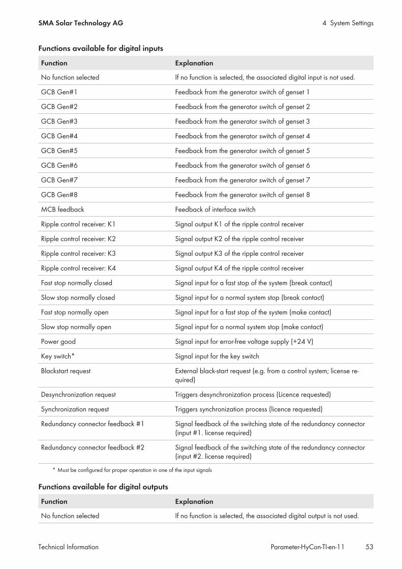
4 System SettingsSMA Solar Technology AG
Technical Information 53Parameter-HyCon-TI-en-11
Functions available for digital inputs
Function Explanation
No function selected If no function is selected, the associated digital input is not used.
GCB Gen#1 Feedback from the generator switch of genset 1
GCB Gen#2 Feedback from the generator switch of genset 2
GCB Gen#3 Feedback from the generator switch of genset 3
GCB Gen#4 Feedback from the generator switch of genset 4
GCB Gen#5 Feedback from the generator switch of genset 5
GCB Gen#6 Feedback from the generator switch of genset 6
GCB Gen#7 Feedback from the generator switch of genset 7
GCB Gen#8 Feedback from the generator switch of genset 8
MCB feedback Feedback of interface switch
Ripple control receiver: K1 Signal output K1 of the ripple control receiver
Ripple control receiver: K2 Signal output K2 of the ripple control receiver
Ripple control receiver: K3 Signal output K3 of the ripple control receiver
Ripple control receiver: K4 Signal output K4 of the ripple control receiver
Fast stop normally closed Signal input for a fast stop of the system (break contact)
Slow stop normally closed Signal input for a normal system stop (break contact)
Fast stop normally open Signal input for a fast stop of the system (make contact)
Slow stop normally open Signal input for a normal system stop (make contact)
Power good Signal input for error-free voltage supply (+24 V)
Key switch* Signal input for the key switch
Blackstart request External black-start request (e.g. from a control system; license re-quired)
Desynchronization request Triggers desynchronization process (Licence requested)
Synchronization request Triggers synchronization process (licence requested)
Redundancy connector feedback #1 Signal feedback of the switching state of the redundancy connector(input #1. license required)
Redundancy connector feedback #2 Signal feedback of the switching state of the redundancy connector(input #2. license required)
* Must be configured for proper operation in one of the input signals
Functions available for digital outputs
Function Explanation
No function selected If no function is selected, the associated digital output is not used.

4 System Settings SMA Solar Technology AG
Technical InformationParameter-HyCon-TI-en-1154
Function Explanation
LED Operation Output for indicator light OPERATION
LED Disturbance Output for indicator light DISTURBANCE
Blackstart done The message appears that the black start was successful (licence re-quired)
Synchronization Output signal to external synchronization device (license required)
Alarm Output Message appears that the Hybrid Controller received an error mes-sage.
Fast Stop active Output as status message of a fast stop
Din1 at MeasDev1 Mirroring of the digital input signal from measuring point #1
Redundancy - reboot other HyCon Output signal for restarting the other Hybrid Controller in redun-dancy mode (license required)
Redundancy Connector switchover Output signal for changing the switching state of the redundancyconnector in redundancy mode (license required)

5 System ControlSMA Solar Technology AG
Technical Information 55Parameter-HyCon-TI-en-11
5 System Control5.1 Control of PV and battery inverters
5.1.1 Control of the PV Power Plant Reactive Power According to ElectricalConsumption
Path: Home > Control Functions > PV & Battery > Reactive Power Management
Parameters Description Value Explanation Defaultvalue
Enable Enables this function Yes Enables the function* Yes
No Disables the function
RpmIslandMode Selects the mode of this functionin case of island operation
Off Reactive power manage-ment for island operationis deactivated.
Off
Fixed CosPhi Reactive power manage-ment for island operationwith set power factor
Load CosPhi Reactive power manage-ment for island operationwith load-dependentpower factor
FixedCosPhiIsland Fixed cosPhi in island operation(only active if selected in RpmIs-landMode)This parameter is only valid if theparameter RpmIslandMode isset to Fixed CosPhi.
-1 to +1 – 0.900
RpmGridMode Determines the mode of this func-tion in case of grid operation
Off Reactive power manage-ment for operation in theutility grid is disabled.
FixedCosPhi
Fixed CosPhi Reactive power manage-ment for operation in theutility grid with set powerfactor
Load CosPhi Reactive power manage-ment for operation in theutility grid with load-de-pendent power factor
FixedCosPhiGrid Fixed cosPhi in grid operation(only active if selected in Rpm-GridMode)This parameter is only valid if theparameter RpmGridMode is setto Fixed CosPhi.
-1 to +1 – +0.900

5 System Control SMA Solar Technology AG
Technical InformationParameter-HyCon-TI-en-1156
Parameters Description Value Explanation Defaultvalue
PvCosPhiMinOx Minimum overexcited power fac-tor which the PV inverters canprovide
0 to +1 – 0.8
PvCosPhiMinUx Minimum underexcited powerfactor which the PV inverters canprovide.
0 to +1 – 0.8
GenCosPhiWarOx If the genset system exceeds thispower factor threshold, a warn-ing message is generated after acertain time has elapsed Gen-CosPhiWarTm.
0 to +1 – 0.800
GenCosPhiWarTm If the genset system exceeds thepower factor GenCosPhi-WarOx or falls below the powerfactor GenCosPhiWarUx, awarning message is generatedafter a certain time has elapsed.
0 s to 86400 s – 10.0 s
GenCosPhiWarUx If the genset system falls belowthis power factor threshold, awarning message is generatedafter a certain time has elapsedGenCosPhiWarTm.
-1 to 0 – -0.800
GridCosPhiWarOx If the utility grid falls below thispower factor threshold, a warn-ing is generated after a certaintime has elapsed GridCosPhi-WarTm.
0 to +1 – 0.700
GridCosPhiWarUx If the utility grid exceeds thepower factor GridCosPhi-WarOx or falls below the powerfactor GridCosPhiWarUx, awarning message is generatedafter a certain time has elapsed.
-1 to 0 – -0.700
GridCosPhiWarTm If the utility grid falls below thispower factor, a warning mes-sage is generated after a certaintime has elapsed GridCosPhi-WarTm.
0 s to 86400 s – 10.0 s
FixedCosPhiBat Fixed cosPhi in grid operation(only active if selected in Rpm-GridMode)
0 to 1 – 0.900
* When the function Reactive Power Management is enabled, the function Reactive Power Control must be disabled Setting thePower Factor Control for the Gensets Using the Reactive Power Release of the PV Inverters.

5 System ControlSMA Solar Technology AG
Technical Information 57Parameter-HyCon-TI-en-11
5.1.2 State-Of-Charge Control of the BatteryThe parameters of the function State of charge can only be set if a battery inverter has been installed.Path: Home > Control Functions > PV & Battery > State of charge
Parameters Description Value Explanation Defaultvalue
Enable Enables this function Yes Enables the function Yes
No Disables the function
UsePvPwr Use of excess PV power for bat-tery chargingIt is advisable to always chargethe battery with excess PV en-ergy.
Yes The battery is ideallycharged with PV en-ergy.
Yes
No The battery is ideallycharged from gensetsor the utility grid
UseFullPvPwr Enables the battery charging withthe entire PV power.
Yes Battery charging withPV energy is enabled.
No
No Battery charging withPV energy is dis-abled.
HysPc Hysteresis of SOC range:• If the battery state of charge
falls below the value of theparameter SocLimLoPc, theHybrid Controller begins tocharge the battery.
• If the battery state of chargeexceeds the sum of theparameters SocLimLoPcand HysPc, theHybrid Controller stopscharging the battery.
0% to 100% – 5 %
SocLimHiPc Upper limit of SOC range 0% to 100% – 80 %
SocLimLoPc Lower limit of SOC range 0% to 100% – 60 %
PwrAtChrMaxPc Maximum setpoint of the Hy-brid Controller to charge the bat-tery based on the available elec-tric power of all battery inverters
0% to 100% – 10 %

5 System Control SMA Solar Technology AG
Technical InformationParameter-HyCon-TI-en-1158
Parameters Description Value Explanation Defaultvalue
PwrAtDisMaxPc Maximum setpoint of the Hy-brid Controller to discharge thebattery based on the availableelectric power of all battery in-verters
0% to 100% 10 %
ChrFromGenTm Time until charging the batterieswith electrical power from thegensets or from the utility grid
0 s to 86400 s – 21600 s
5.2 Processing of the received measured values and parameters
5.2.1 Selecting a Measuring Point for ControlThe measuring point, where voltage, frequency and power of the hybrid system are recorded, can be selected via thePOI Configuration page.Path: Home > Control Functions > Aggregate > POI Configuration
Parameters Description Value Explanation Defaultvalue
FrqPoiMeasDevIdx Selection of measuring point forfrequency measurement
1st measuring point – –
2nd measuring point –
VtgPoiCalcMode Mode for voltage measurement Between L1 and L2 Measurement be-tween L1 and L2
BetweenL1 andL2
Average of all 3PH Average of all mea-sured voltages (L1-L2,L1-L3 and L2-L3)
VtgPoiMeasDevIdx Selection of measuring point forfrequency measurement
1st measuring point – –
2nd measuring point –
PwrAtPoiCalcMode Mode for capturing the activepower
Selected device Active power of a de-vice
Sum ofselecteddevices
Sum of selected de-vices
Sum of active powerof all selected de-vices
Average of selecteddevices
Average activepower of all selecteddevices
PwrAtPoiMeasDevIdx Selection of measuring point forthe active power measurement
1st measuring point – –
2nd measuring point –

5 System ControlSMA Solar Technology AG
Technical Information 59Parameter-HyCon-TI-en-11
Parameters Description Value Explanation Defaultvalue
PwrRtPoiCalcMode Mode for capturing the reactivepower
Selected device Reactive power of adevice
Sum ofselecteddevices
Sum of selected de-vices
Sum of reactivepower of all selecteddevices
Average of selecteddevices
Average reactivepower of all selecteddevices
PwrRtPoiMeasDevIdx Selection of measuring point forthe reactive power measurement
1st measuring point – –
2nd measuring point –
5.2.2 Other Parameters for Processing the Received Measured Values andParameters
Path: Home > Control Functions > Aggregate > Miscellaneous
Parameters Description Value Explanation Defaultvalue
SocAvgCalcMode Selects the mode for calculatingthe state of charge of all batteries
SOC State of charge of thebattery based on thenominal battery ca-pacity
Energy
Energy State of charge of thebattery as availableelectrical power
SafePctPv Share of the current MPP powerof the PV plant which will still beavailable in case of PV drops
0 % to 100 % – 20 %
EnaPvPwrRt-MaxRamp
Enables ramp down of nominalreactive power at low activepower.
No Reactive power is notramped down
No
Yes Reactive power isramped down
PvPwrAtThrsldHysPc Hysteresis for switching on andoff the nominal reactive powerramp of one device.
0 % to 100 % - 1.0 %
PvPwrAtThrsldPc Threshold for ramping the nomi-nal reactive power of a deviceup or down, in % of nominal ac-tive power of device.
0 % to 100 % - 0.0 %
PvPwrAtThrsldTm Switch-on delay for ramping thenominal reactive power up ordown in s.
0 to 600 - 10 %s

5 System Control SMA Solar Technology AG
Technical InformationParameter-HyCon-TI-en-1160
Parameters Description Value Explanation Defaultvalue
PvPwrRtMaxRate Maximum rate of PV devicesnominal reactive power in MW/min
0 to 1000000 - 1.00MW/min
ComQualiMinPcBat Minimum communication qualityvalue for valid system power cal-culation of battery system.
0 % to 100 % - 60 %
ComQualiMinPcGen Minimum communication qualityvalue for valid system power cal-culation of genset system.
0 % to 100 % - 60 %
ComQualiMinPcGrid Minimum communication qualityvalue for valid system power cal-culation of grid system.
0 % to 100 % - 60 %
ComQualiMinPcLoad Minimum communication qualityvalue for valid system power cal-culation of load system.
0 % to 100 % - 60 %
ComQualiMinPcPv Minimum communication qualityvalue for valid system power cal-culation of PV system.
0 % to 100 % - 60 %
5.3 Calculation of the parameters to be output
5.3.1 Setpoint Change Rate for PV Inverters and GensetsPath: Home > Control Functions > Dispatch > Ramps
Parameters Description Value Explanation Default value
GenPwrMngmt-TransRamp:
Maximum rate of active powersetpoint for PV system in case oftoo low reserve power.
0%/s to 100%/s - 5%/s
PvPwrAtFall-RateMax
Maximum negative rate of theactive power setpoint for PV in-verters in percent per second (%/s) of related rated inverter power
0%/s to 1000%/s - 20%/s
PvPwrAtRiseR-ateMax
Maximum positive rate of the ac-tive power setpoint for PV invert-ers in percent per second (%/s)of related rated inverter power
0%/s to 1000%/s - 5%/s
BatPwrAtFall-RateMax
Maximum negative rate of activepower setpoint for battery systemrelated to the actual power.
0%/s to 1000%/s - 20%/s
BatPwrAtRiseR-ateMax
Maximum positive rate of changeof active power setpoint for thestorage system related to the cu-mulated rated power of the bat-tery inverter
0%/s to 1000%/s - 20%/s

5 System ControlSMA Solar Technology AG
Technical Information 61Parameter-HyCon-TI-en-11
Parameters Description Value Explanation Default value
PwrRtFall-RateMax
Maximum negative rate ofchange of reactive power set-point for the hybrid system re-lated to the cumulated ratedpower of the PV and battery in-verter
0%/s to 1000%/s - 20%/s
PwrRtRiseR-ateMax
Maximum positive rate of changeof reactive power setpoint for thehybrid system related to the cu-mulated rated power of the PVand battery inverter
0%/s to 1000%/s - 20%/s
PwrAtReset-ThrsldPc
Limiting value for the reset of theactive power setpoint to the cur-rent active power value mea-sured (related to the parameterPwrAtNomPoi)
0% to 100% - 5 %
EnaPv-CloudRamp
Enables a slow increase of PVpower when cloud shading dis-appears.The function is based on solar ir-radiation measured. The modefor measuring solar irradiation isspecified by PwrAtMode. Theadjustment rate of the PV poweris limited by PwrAtRateMax.
No Function is disabled. No
Yes Function is enabled.
SlowStopRamp When switching from operationmode OPERATE to STANDBY,the Hybrid Controller reduces theactive- and reactive power set-points for the PV power plant andstorage system according to theparameters set on this page.SlowStopRamp specifies thetime in which the change must beimplemented.
0 s to 3600 s - 20 s
SafetyRampTm When switching from operationmode OPERATE to SAFETY, theHybrid Controller reduces the ac-tive- and reactive power setpointsfor the PV power plant and stor-age system according to the pa-rameters set on this page.SafetyRampTm specifies thetime in which the change must beimplemented.
0 s to 3600 s - 10 s

5 System Control SMA Solar Technology AG
Technical InformationParameter-HyCon-TI-en-1162
Parameters Description Value Explanation Default value
PwrAtRateMax Maximum rate of change of ac-tive power setpoint for entire hy-brid system
1 MW/min to100000 MW/min
- 100 MW/min
PwrAtMode Defines the operating state inwhich PwrAtRateMax orPwrAtSpntFilterTm is enabled.
None PwrAtRateMax isdisabled.
None
GEN IOP Genset IsolatedOperation: Gensetsprimarily supply thehybrid system.
GRID MOP Grid Mains Opera-tion: The utility gridprimarily supplies thehybrid system.
GRID MOP GENIOP
Genset IsolatedOperation andGrid Mains Opera-tion: The utility gridand gensets primarilysupply the hybrid sys-tem.
PwrAtSpntFil-terTm
Filter time of the active powerspecification, if the filter time isgreater than 0, this is used in-stead of the PwrAtRateMaxramp.
0 s to 3600 s - 0 s
PwrRtRateMax Maximum rate of change of reac-tive power setpoint for entire hy-brid system
1 MW/min to100000 MW/min
- 100 MW/min

5 System ControlSMA Solar Technology AG
Technical Information 63Parameter-HyCon-TI-en-11
Parameters Description Value Explanation Default value
PwrRtMode Defines the operating state inwhich PwrRtRateMax orPwrAtSpntFilterTm is enabled.
None PwrAtRateMax isdisabled.
None
GEN IOP Genset IsolatedOperation: Gensetsprimarily supply thehybrid system.
GRID MOP Grid Mains Opera-tion: The utility gridprimarily supplies thehybrid system.
GRID MOP GENIOP
Battery IsolatedOperation andGrid Mains Opera-tion: The utility gridand gensets primarilysupply the hybrid sys-tem.
PwrRtSpntFil-terTm
Filter time of the reactive powersetpoints, if the filter time isgreater than 0, this is used in-stead of the PwrAtRateMaxramp.
0 s to 3600 s - 0 s
EnaCa-pacRamp
Enables the capacity ramp to 0active power of battery system.
Yes Capacity ramp atlow discharge andcharge energy is en-abled
No
No Capacity ramp atlow discharge andcharge energy is dis-abled
CapacP-wrAtRateMax
Set active power default to 0when battery is full or empty.
0 MW/min to10000000 MW/min
- 100 MW/min
CapacRemain Residual capacity for charging ordischarging.
0 MWh to1000000 MWh
- 0.100 MWh
5.3.2 Options for Specifying the Reserve Power Setpoint of the GensetsPath: Home > Control Functions > Dispatch > Genset setpoints
Parameters Description Value Default value
GenSpntTrigPctNeg The reserve power setpoint will be transmit-ted immediately to the genset system if a neg-ative change of the setpoint is greater thanthis percentage of the connected ratedgenset power.
0% to 10000% 20 %
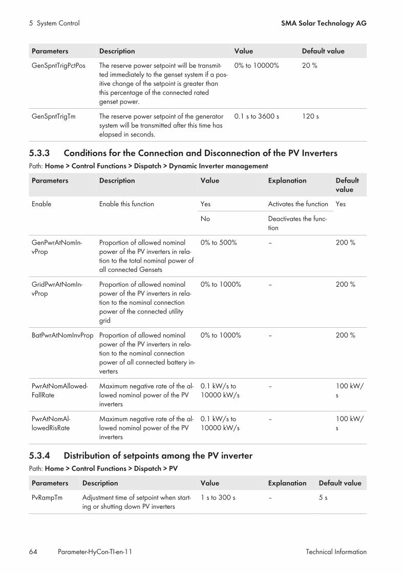
5 System Control SMA Solar Technology AG
Technical InformationParameter-HyCon-TI-en-1164
Parameters Description Value Default value
GenSpntTrigPctPos The reserve power setpoint will be transmit-ted immediately to the genset system if a pos-itive change of the setpoint is greater thanthis percentage of the connected ratedgenset power.
0% to 10000% 20 %
GenSpntTrigTm The reserve power setpoint of the generatorsystem will be transmitted after this time haselapsed in seconds.
0.1 s to 3600 s 120 s
5.3.3 Conditions for the Connection and Disconnection of the PV InvertersPath: Home > Control Functions > Dispatch > Dynamic Inverter management
Parameters Description Value Explanation Defaultvalue
Enable Enable this function Yes Activates the function Yes
No Deactivates the func-tion
GenPwrAtNomIn-vProp
Proportion of allowed nominalpower of the PV inverters in rela-tion to the total nominal power ofall connected Gensets
0% to 500% – 200 %
GridPwrAtNomIn-vProp
Proportion of allowed nominalpower of the PV inverters in rela-tion to the nominal connectionpower of the connected utilitygrid
0% to 1000% – 200 %
BatPwrAtNomInvProp Proportion of allowed nominalpower of the PV inverters in rela-tion to the nominal connectionpower of all connected battery in-verters
0% to 1000% – 200 %
PwrAtNomAllowed-FallRate
Maximum negative rate of the al-lowed nominal power of the PVinverters
0.1 kW/s to10000 kW/s
– 100 kW/s
PwrAtNomAl-lowedRisRate
Maximum negative rate of the al-lowed nominal power of the PVinverters
0.1 kW/s to10000 kW/s
– 100 kW/s
5.3.4 Distribution of setpoints among the PV inverterPath: Home > Control Functions > Dispatch > PV
Parameters Description Value Explanation Default value
PvRampTm Adjustment time of setpoint when start-ing or shutting down PV inverters
1 s to 300 s – 5 s

5 System ControlSMA Solar Technology AG
Technical Information 65Parameter-HyCon-TI-en-11
Parameters Description Value Explanation Default value
FallbackPc In case of a communication failure, PVinverters will feed in this percentage ofrated power.
1% to 100% – 10 %
FallbackTmPv In case of a communication failure, thePV inverter enables FallbackPc after acertain time has elapsed.
1 s to 86400 s – 20 s
PvPwrRtDis-patchMode
Determines the mode based on whichthe setpoint for the reactive power isdistributed to the PV inverters.
Nominal Distribution ofthe setpointbased on therated power ofeach PV in-verter
Nominal
Same CosPhi Assignment ofan uniform set-point for thecos φ to all PVinverters.
5.3.5 Distribution of setpoints among the battery invertersPath: Home > Control Functions > Dispatch > Battery
Parameters Description Value Explanation Defaultvalue
BatDispatch-Mode
Determines the mode based on whichthe setpoint for the active power is dis-tributed to the battery inverters in thehybrid system.
Power Distribution of the setpointaccording to the chargingand discharging activepower of each battery in-verter
Energy
Energy Distribution of the setpointbased on the charging anddischarging energy of eachbattery inverter
C rate* Distribution of the setpointsfor the ramp rates accord-ing to the C rate of eachbattery inverterBut: Distribution of the set-points for energy still ac-cording to the chargingand discharging energy ofeach battery inverter
Nominal Distribution of the setpointbased on the rated powerof each battery inverter

5 System Control SMA Solar Technology AG
Technical InformationParameter-HyCon-TI-en-1166
Parameters Description Value Explanation Defaultvalue
BatPwrRtDistri-butionMode
Determines the mode based on whichthe setpoint for the reactive power isdistributed to the battery inverters.
Same CosPhi Assignment of an uniformsetpoint for the cos φ to allbattery inverters.
SameCosPhi
Same PowerRt Distribution of the setpointaccording to the chargingand discharging reactivepower of each battery in-verter
EnaSocEqual Enables the automatic compensation ofthe states of charge.**
No Automatic compensation ofthe states of charge is dis-abled.
No
Yes Automatic compensation ofthe states of charge is en-abled.
BatRampTm Adjustment time of setpoint when start-ing or shutting down of battery inverters
1 s to 300 s – 5 s
BatStdbyStrTm Battery standby timer before startingthe inverter. (So that the battery rackshave enough time to connect.)
0 s to 3600 s - 15 s
SocRampTm The battery inverter regularly reportsthe current state of charge to the Hy-brid Controller.Transmitted values are filtered withinthe period SocRampTm to allow aslow adaptation of the control processin the Hybrid Controller.
1 s to 60 s – 5 s
SpntDistFilterTm Filter time constant to supplement theparameter SocRampTm, which causesan additional limitation of the ramprate.
1 s to 600 s – 12 s
SpntRedist-MaxPc
Percentage of the rated inverter powerthat can be used for automatic com-pensation of the states of charge.
0 % to 10 % – 1 %
SocDevMaxAl-lowed
Maximum permissible deviation be-tween the state of charge of a batteryinverter and the average state ofcharge of all battery inverters. If thisvalue is exceeded, the setpoint for au-tomatically compensating the state ofcharge becomes effective.
1 % to 10 % – 2 %
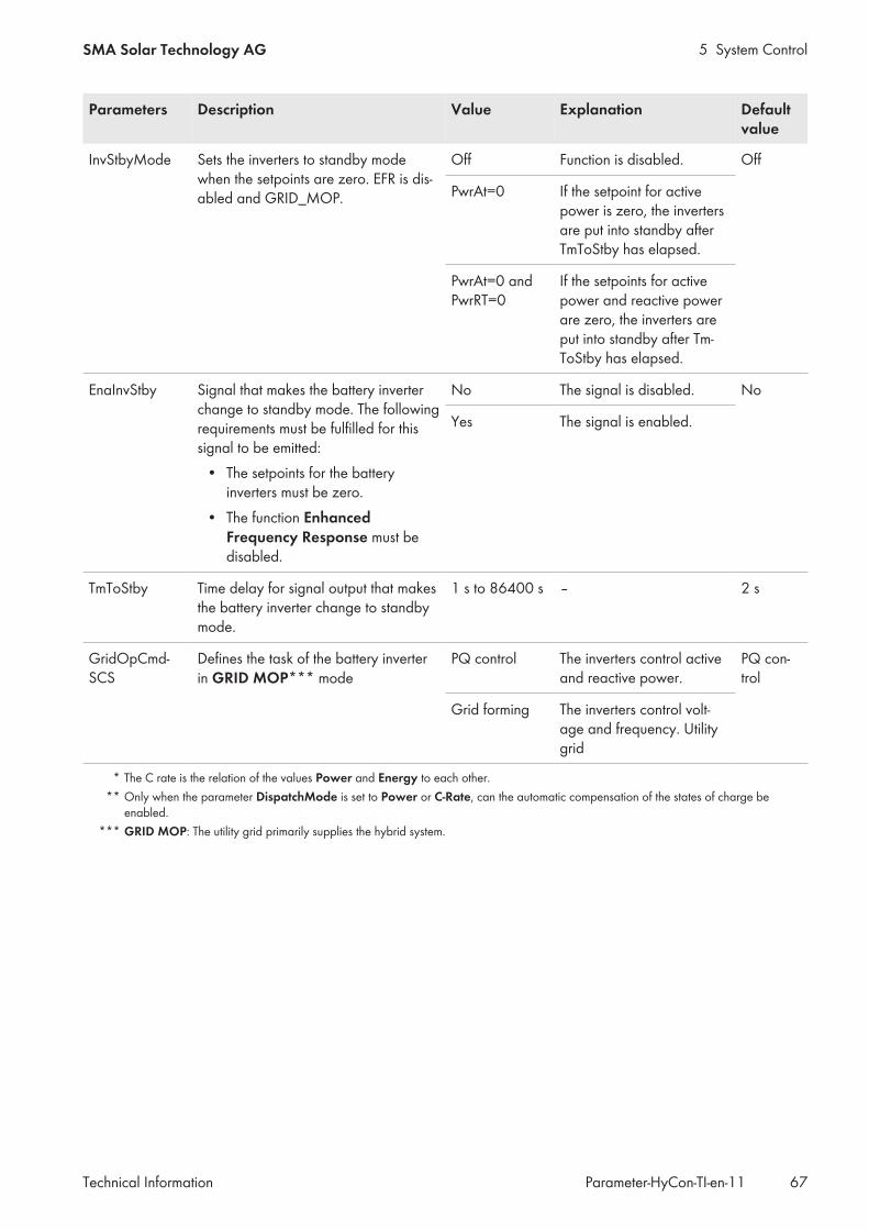
5 System ControlSMA Solar Technology AG
Technical Information 67Parameter-HyCon-TI-en-11
Parameters Description Value Explanation Defaultvalue
InvStbyMode Sets the inverters to standby modewhen the setpoints are zero. EFR is dis-abled and GRID_MOP.
Off Function is disabled. Off
PwrAt=0 If the setpoint for activepower is zero, the invertersare put into standby afterTmToStby has elapsed.
PwrAt=0 andPwrRT=0
If the setpoints for activepower and reactive powerare zero, the inverters areput into standby after Tm-ToStby has elapsed.
EnaInvStby Signal that makes the battery inverterchange to standby mode. The followingrequirements must be fulfilled for thissignal to be emitted:
• The setpoints for the batteryinverters must be zero.
• The function EnhancedFrequency Response must bedisabled.
No The signal is disabled. No
Yes The signal is enabled.
TmToStby Time delay for signal output that makesthe battery inverter change to standbymode.
1 s to 86400 s – 2 s
GridOpCmd-SCS
Defines the task of the battery inverterin GRID MOP*** mode
PQ control The inverters control activeand reactive power.
PQ con-trol
Grid forming The inverters control volt-age and frequency. Utilitygrid
* The C rate is the relation of the values Power and Energy to each other.** Only when the parameter DispatchMode is set to Power or C-Rate, can the automatic compensation of the states of charge be
enabled.*** GRID MOP: The utility grid primarily supplies the hybrid system.

5 System Control SMA Solar Technology AG
Technical InformationParameter-HyCon-TI-en-1168
5.3.6 Distribution of setpoints among all PV invertersPath: Home > Control Functions > Dispatch > PV & Battery
Parameters Description Value Explanation Default value
PvBatSp-ntSplitPc
Distribution of the reactive power set-point among the PV and battery invert-ersExamples:SpntSplitPc = 100%: 100% allotted tothe PV power plant and 0% to the stor-age system.SpntSplitPc = 0%: 0% allotted to thePV power plant and 100% to the stor-age system.
0% to 100% – 80 %
EnaPrioBatP-wrAt
Enables the prioritization of the activepower setpoints of the battery.
Yes Battery feed-inis preferred toPV feed-in.
No
No PV feed-in ispreferred tobattery feed-in.
PwrRtDispacht-Mode
Determines the mode based on whichthe setpoint for the reactive power isdistributed to the PV and battery invert-ers.
Split percentage Specified bysetting the pa-rameter PvBat-SpntSplitPc.
Split percent-age
Nominal Specified bysetting therated power ofall active invert-ers.
5.4 Battery-supported operation
5.4.1 Parameters for PV Yield ForecastPath: Home > Control Functions > Battery Isolated Operation > Energy Management
Parameters Description Value Explanation Defaultvalue
Enable Enables the Energy Management function. Yes Enables the function No
No Disables the function
EnaDomAt-Night
Allows the transition to diesel-off mode atnight.
Yes Transition is also al-lowed at night.
Yes
No Transition is not al-lowed at night.

5 System ControlSMA Solar Technology AG
Technical Information 69Parameter-HyCon-TI-en-11
Parameters Description Value Explanation Defaultvalue
AutoMode Enables the automatic switch to battery-sup-ported operation.
Yes Automatic switch ispossible.
No
No Automatic switch isnot possible.
GeoCoordLat Latitude at which the hybrid system is in-stalled.
-90° to +90° – 51.31 °*
GeoCoordLong Longitude at which the hybrid system is in-stalled.
-180° to+180°
– 9.48 °*
PvModB Orientation of the PV modules with regard tothe north direction (azimuth)
0° to 180° 0°: Orientation to thenorth180°: Orientation tothe south
180 °*
PvModH Orientation of the PV modules with regard tothe horizon
0° to 90° – 5 °
MinDomTm Minimum time for the operating mode "DieselOff" which is necessary for an automatictransmission
300 s to36000 s
– 1800 s
AvgLoad Average electrical consumption for forecast-ing the time that the hybrid system can re-main in the "Diesel Off" operating mode toestimate the projected charging energy
1 kW to10000 kW
The expected aver-age load of the hy-brid system must beentered here.
500 kW
AvgLoadDef-Sect
Average load (DEFAULT section) for estimat-ing the forecasted load energy. This parame-ter is for simple EMS!
1 kW to10000 kW
– 500 kW
* Example for Kassel
5.4.2 Parameters for Frequency ControlPath: Home > Control Functions > Battery Isolated Operation > Frequency Control
Parameters Description Value Explanation Defaultvalue
Enable Enables the Frequency Controlfunction.
Yes Enables the function No
No Disables the function
FrqFilterTm Filter time constant for measuringthe current frequency
0.1 s to 30.0 s – 3.0 s
FrqMaxWar Warning threshold for overfre-quency
40 Hz to 70 Hz – 52 Hz
FrqMinWar Warning threshold for underfre-quency
40 Hz to 70 Hz – 48 Hz

5 System Control SMA Solar Technology AG
Technical InformationParameter-HyCon-TI-en-1170
Parameters Description Value Explanation Defaultvalue
FrqOfsGenSync Frequency offset for synchroniz-ing the gensets to the local utilitygrid
-0.5 Hz to +0.5 Hz – -0.05 Hz
FrqOfsGridSync: Frequency offset for synchroniz-ing the utility grid to the local util-ity grid
-0.2 Hz to +0.2 Hz +0.05 Hz
FrqSpnt Frequency setpoint in the "DieselOff" operating mode
40 Hz to 70 Hz – 50 Hz
IntGain Integral gain for the control share 0 to 500 – 1
IntLimAwu Threshold for the integral share offrequency control, e.g.:
• IntLimAwu=1: The batteryinverter's entire active powermay be used for thefrequency control.
• IntLimAwu=0.2: 20% ofthe battery inverter's activepower may be used for thefrequency control.
0 to 2 – 0.2
PropGain Proportional gain for the controlshare
0 to 100 – 1
5.4.3 Parameters for Voltage ControlPath: Home > Control Functions > Battery Isolated Operation > Voltage Control
Parameters Description Value Explanation Defaultvalue
Enable Enables the Voltage Controlfunction.
Yes Enables the function No
No Disables the function
IntGain Integral gain for the control share 0 to 100 – 1
IntLimAwu Threshold for the integral share ofvoltage control
0 to 2 – 0.5
PropGain Proportional gain for the controlshare
0 to 100 – 1
VtgFilter Tm Filter time constant for measuringthe current voltage
0.1 s to 30.0 s – 3.0 s
VtgMaxWar Warning threshold for overvolt-age
1 V to 100000 V – 450 V
VtgMinWar Warning threshold for undervolt-age
1 V to 100000 V – 330 V

5 System ControlSMA Solar Technology AG
Technical Information 71Parameter-HyCon-TI-en-11
Parameters Description Value Explanation Defaultvalue
VtgNom Rated voltage of hybrid system 1 V to 220000 V – 400 V
VtgOfsGenSync Voltage offset for synchronizingthe gensets to the local utility grid
-1000 V to 1000 V – -2.0 V
VtgSpnt Voltage setpoint in the "DieselOff" operating mode
1 V to 100000 V – 400 V
5.4.4 Parameter for black startThis section describes the parameter settings that must be set for the preparation of a black start (further information forblack-start execution see user manual of Hybrid Controller).Path: Home > Control Functions > Battery Isolated Operation > Black Start
Parameters Description Value Explanation Defaultvalue
AvgLoadPc Necessary power of black start-capable inverters in % related tothe estimated minimum demandof the electrical loads
0.01% to 1000% – 70 %
VtgRampUpTm Ramp-up time of VtgSpntStrUpfor nominal voltage of hybrid sys-tem during BlackStart_RampUp
0.01 s to 30 s – 5 s
VtgSpntStrUpPc Voltage setpoint for black-startpreparation in % related to nomi-nal voltage of hybrid system
0.01% to 130% – 20 %
5.5 Functions for grid support
5.5.1 General Functions for Grid SupportPath: Home > Control Functions > Gridservice > Gridservice
Parameters Description Value Explanation Defaultvalue
EnaExtAtSpnt Defines whether the charging and dis-charging of battery is based on an ac-tive power setpoint. Energy is drawnfrom or fed into the utility grid duringthe charging and discharging process.The setpoint source is defined by theExtSpntSrc parameter.
Yes Enables the function No
No Disables the function
EnaExtRtSpnt Defines whether the charging and dis-charging of battery is based on a reac-tive power setpoint. Energy is drawnfrom or fed into the utility grid duringthe charging and discharging process.The setpoint source is defined by theExtSpntSrc parameter.
Yes Enables the function No
No Disables the function
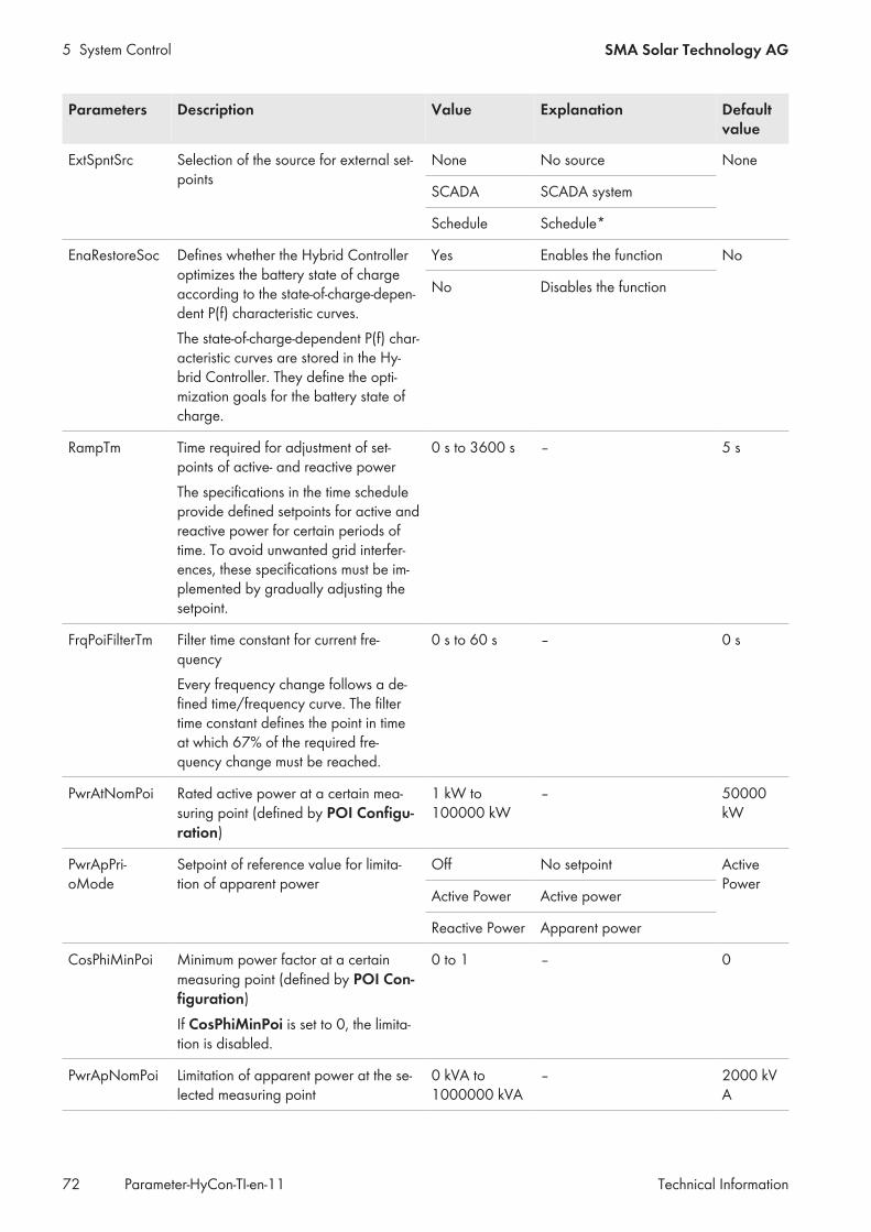
5 System Control SMA Solar Technology AG
Technical InformationParameter-HyCon-TI-en-1172
Parameters Description Value Explanation Defaultvalue
ExtSpntSrc Selection of the source for external set-points
None No source None
SCADA SCADA system
Schedule Schedule*
EnaRestoreSoc Defines whether the Hybrid Controlleroptimizes the battery state of chargeaccording to the state-of-charge-depen-dent P(f) characteristic curves.The state-of-charge-dependent P(f) char-acteristic curves are stored in the Hy-brid Controller. They define the opti-mization goals for the battery state ofcharge.
Yes Enables the function No
No Disables the function
RampTm Time required for adjustment of set-points of active- and reactive powerThe specifications in the time scheduleprovide defined setpoints for active andreactive power for certain periods oftime. To avoid unwanted grid interfer-ences, these specifications must be im-plemented by gradually adjusting thesetpoint.
0 s to 3600 s – 5 s
FrqPoiFilterTm Filter time constant for current fre-quencyEvery frequency change follows a de-fined time/frequency curve. The filtertime constant defines the point in timeat which 67% of the required fre-quency change must be reached.
0 s to 60 s – 0 s
PwrAtNomPoi Rated active power at a certain mea-suring point (defined by POI Configu-ration)
1 kW to100000 kW
– 50000kW
PwrApPri-oMode
Setpoint of reference value for limita-tion of apparent power
Off No setpoint ActivePower
Active Power Active power
Reactive Power Apparent power
CosPhiMinPoi Minimum power factor at a certainmeasuring point (defined by POI Con-figuration)If CosPhiMinPoi is set to 0, the limita-tion is disabled.
0 to 1 – 0
PwrApNomPoi Limitation of apparent power at the se-lected measuring point
0 kVA to1000000 kVA
– 2000 kVA

5 System ControlSMA Solar Technology AG
Technical Information 73Parameter-HyCon-TI-en-11
Parameters Description Value Explanation Defaultvalue
PwrRtNomPoi Limitation of reactive power at the se-lected measuring point
0 kVAr to1000000 kVAr
– 1000 kVAr
PwrAtPoiFil-terTm
Filter time constant for measuring thecurrent active power
0 s to 600 s – 0 s
PwrRtPoiFil-terTm
Filter time constant for measuring thecurrent reactive power
0 s to 600 s – 0 s
* The time schedule defines parameter settings depending on date and time (further information on time schedule see user manual ofHybrid Controller).
5.5.2 Parameter for SOC Management of Battery InverterPath: Home > Control Functions > Gridservice > SOC Management
Parameters Description Value Explanation Defaultvalue
Enable Activates the SOC Manage-ment function.
No Disables the function No
Yes Enables the function
HysPc Hysteresis of SOC limits forcharging and discharging of bat-tery
0% to 100% – 1.00 %
PwrAtChrMaxPc Percentage of the maximumavailable charging power to limitthe calculated setpoint CtrlGain
0% to 100% – 10.00 %
PwrAtDisMaxPc Percentage of the maximumavailable discharging power tolimit the calculated setpoint Ctrl-Gain
0% to 100% – 10.00 %
SocLimHiPc Upper limit of SOC range 0% to 100% – 60.00 %
SocLimLoPc Lower limit of SOC range 0% to 100% – 40.00 %
SocTargetPc Control target for battery state ofcharge
0% to 100% – 50 %
TmToNextPeriod If the SOC band is reachedwithin this time frame before thenext billing period, the SOCmode is extended by one period.
0 s to 1500 s – 300 s

www.SMA-Solar.com


![HC900 Hybrid Controller Technical p Traducir[1]](https://static.fdocuments.in/doc/165x107/55cf97b5550346d033931e82/hc900-hybrid-controller-technical-p-traducir1.jpg)