
Monoblock directional control valves MDT MDT - Directional ...

298
Technical Information, MDT – Index
MDT - Multi Directional Turning Page
General information . . . . . . . . . . . . . . . . . . . . . . . . . . . . . . . . . 299Code keys . . . . . . . . . . . . . . . . . . . . . . . . . . . . . . . . . . . . . . . . . 300 - 304Toolholder selection . . . . . . . . . . . . . . . . . . . . . . . . . . . . . . . . . 305 - 307Insert selection and grades. . . . . . . . . . . . . . . . . . . . . . . . . . . . 308 - 310Special applications . . . . . . . . . . . . . . . . . . . . . . . . . . . . . . . . . 312 - 313Application technique . . . . . . . . . . . . . . . . . . . . . . . . . . . . . . . . 314 - 319Cutting data . . . . . . . . . . . . . . . . . . . . . . . . . . . . . . . . . . . . . . . 321 - 325Troubleshooting . . . . . . . . . . . . . . . . . . . . . . . . . . . . . . . . . . . . 327 - 328

299
MDT – General information
The Seco MDT (Multi Directional Turning) system consists of holders and inserts for external radial, external axial and internal machining.
The system can be used for• Turning• Profiling• Grooving• Cutting off• Threading
Suitable applications are turning of parts with many different diameters, complicated profiles and grooves. For complex parts of this type several standard and special tools can be replaced by one Seco MDT tool. Savings can be achieved through fewer toolchanges and reduced tool stock.
Seco MDT has a unique insert clamping method.A combination of v top clamp and serrated contact surfacesbetween the insert bottom and toolholder offers superb stability.The relatively long inserts also increase the stability.
The excellent stability gives a number of benefits• Improved safety• Increased cutting data• Good surface finish• Less risk of vibrations• Good repeatability (+/–.001)
300
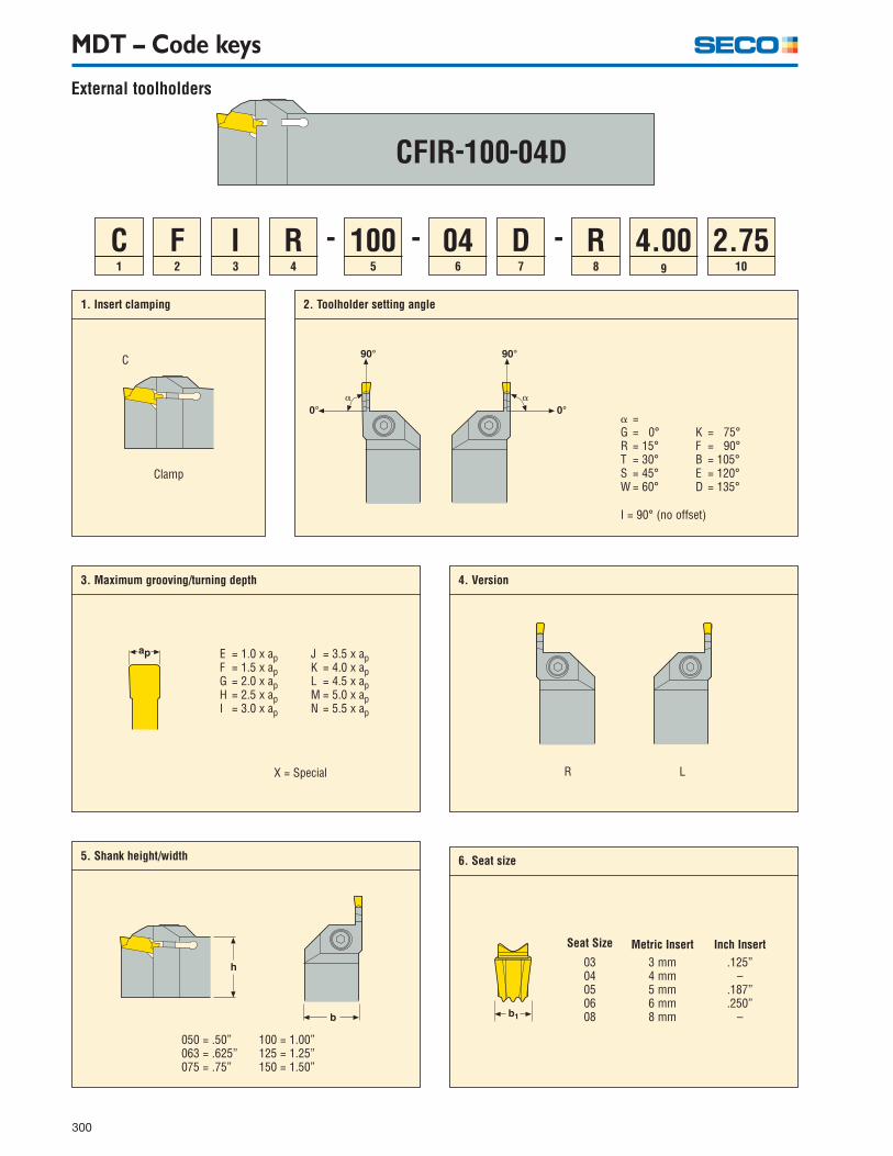
1
C2
F3
I4
R5
1006
049
4.0010
2.758
R
1. Insert clamping
C
Clamp
3. Maximum grooving/turning depth 4. Version
2. Toolholder setting angle
� =G = 0°R = 15°T = 30°S = 45°W = 60°
K = 75°F = 90°B = 105°E = 120°D = 135°
R LX = Special
5. Shank height/width
050 = .50”063 = .625”075 = .75”
100 = 1.00”125 = 1.25”150 = 1.50”
MDT – Code keys
6. Seat size
0304050608
Seat Size
3 mm4 mm5 mm6 mm8 mm
Metric Insert.125”
–.187”.250”
–
Inch Insert
External toolholders
7
D
E = 1.0 x apF = 1.5 x apG = 2.0 x apH = 2.5 x apI = 3.0 x ap
J = 3.5 x apK = 4.0 x apL = 4.5 x apM = 5.0 x apN = 5.5 x ap
I = 90° (no offset)
- - -

301
7. Tool length
A = 4”B = 4.5”C = 5”D = 6”E = 7”
8. Tang curvature direction
9. Maximum diameter
Additional informationfor axial machining
10. Minimum diameter
Additional informationfor axial machining
MDT – Code keys
R
L
4.00 = 4.00 in (D1) 2.75 = 2.75 in (D2)
Additional information for axial machining
External toolholders

302
1
A2
244
G7
043
C5
G6
R
1. Toolholder type
A = Steel with coolant passageS = Solid steel
2. Shank diameter 3. Insert clamping
4. Toolholder setting angle
Clamp
5. Maximum grooving/turning depth
6. Version
R
7. Seat size
MDT – Code keys
- -
C
� =G = 0°R = 15°T = 30°S = 45°W = 60°
K = 75°F = 90°B = 105°E = 120°D = 135°
L
E = 1.0 x apF = 1.5 x apG = 2.0 x apH = 2.5 x apI = 3.0 x ap
J = 3.5 x apK = 4.0 x apL = 4.5 x apM = 5.0 x apN = 5.5 x ap
X = Special
10 = .625”12 = .75”16 = 1.0”20 = 1.25”24 = 1.5”
Internal toolholders
03040506
Seat Size
3 mm4 mm5 mm6 mm
Metric Insert
.125”–
.187”
.250”
Inch Insert

303
1
L3
M4
F2
C9
18710
MT8
A
1. Shape 3. Tolerances
4. Insert type 6. Insert gauge width 7. Corner radius
Single Endedwith Chipbreaker
Double Endedwith Chipbreakers
Single Endedwithout Chipbreaker
Double Endedwithout Chipbreakers
5. Insert gauge length
10. Insert type code
FT = Chipbreaker for Fine turningMC = Chipbreaker for deep grooving and parting offMG = Chipbreaker for Medium groovingMP = Chipbreaker for Medium profilingMT = Chipbreaker for Medium turningFG = For lockringsDY = For dynamic o-ringsST = For static o-ringsR = For radiusD76 = For thread undercutsMCR/L = Right or left hand version with a speci- fied setting angle
MDT – Code keys
- -
Rectangular
R
F
N
A
5
166
057
05
L
2. Front clearance angle
A = 3°B = 5°C = 7°D = 15°E = 20°
Tol.class
Tolerance ± inch For insert widthb1 inch
b1 d r l .125 .187 .250
M .002 .002 .002
m
.003 .004 • • •
Seat size
02 = .008 (0.2 mm)05 = .020 (0.5 mm)
9. Insert width
8. Inch Size
Inserts, inch
125 = .125”187 = .187”250 = .250”
03 = 3.0 mm04 = 4.0 mm05 = 5.0 mm06 = 6.0 mm

304
1
L3
M4
F2
C9
040011
MT8 10
1. Shape 3. Tolerances
4. Insert type 6. Insert gauge width 7. Corner radius
Single endedwith chipbreaker
Double endedwith chipbreaker
Single endedwithout chipbreaker
Double endedwithout chipbreaker
5. Insert gauge length
11. Insert type code
FT = Chipbreaker for Fine turningMC = Chipbreaker for deep grooving and parting offMG = Chipbreaker for Medium groovingMP = Chipbreaker for Medium profilingMT = Chipbreaker for Medium turningFG = For lockringsDY = For dynamic o-ringsST = For static o-ringsR = For radiusD76 = For thread undercutsMCR/L = Right or left hand version with a speci- fied setting angle
MDT – Code keys
- -
Rectangular
R
F
N
A
5
166
047
08
L
2. Front clearance angle
C = 7°
Tol.class
Tolerance ± mm For insert widthb1 mm
b1 d r l 3 4 5 6 8
G
M
0.025
0.05
0.025
0.05
0.025
0.05
0.040 •
•
•
•
•
•
•
•
•
•0.08
Seat size
M0,00 = Round02 = .008”04 = .016”05 = .020”
06 = .024”08 = .031”10 = .039”12 = .047”
9. Insert width
10. Version8. Side clearance radius
L R
LR
Inserts, metric
0300 = .118” (3 mm)0400 = .157” (4 mm)0500 = .197” (5 mm)0600 = .236” (6 mm)0800 = .315” (8 mm)

305
MDT – Toolholders
CFIR/L – Basic choice• For external turning, profiling and grooving• Maximum working depth 3 x the insert width (can be limited by double ended inserts)• Size 16 – For general machining• Size 30 – For heavy machining
CFMR/L – Long reach• For external turning, profiling and grooving• Maximum working depth 5 x the insert width• Single ended inserts should be used• Size 16 – For general machining• Size 30 – For heavy machining
CFOR/L, CFPR/L, CFTR/L – Extra long reach, 6 x insert width up to 8.5 x insert width (3 and 4 mm inserts).• For grooving and cut-off• Maximum grooving depth is 1.00”• Single ended inserts should be used• Size 16 – For general machining

306
MDT – Toolholders
Single ended blades• Mainly for tailor made applications• Holder with both right and left hand blade mounting available• Size 16 – For general machining
C_IR/L – Axial machining• For axial turning, profiling and grooving• Maximum working depth 3 x the insert width (can be limited by double ended inserts)• These toolholders demand that the first cut must be made between two specified diameters (see code key)• Size 16 – For general machining• Size 30 – For heavy machining
CGIR
CFIL
MDT16
MDT13
CG_R/L Internal machining• For internal turning, profiling and grooving• Maximum working depth 1–3.5 x the insert width for size 13• Maximum working depth 2 x the insert width for size 16• For ’through’ coolant supply• Size 13 – For machining in small bore sizes• Size 16 – For general machining

307
Modular holders• For axial turning, profiling and grooving• Maximum working depth up to 3x the insert width• These toolholders demand that the first cut must be made between two specified diameters (see code key)• Size 13 – For axial machining at small diameters
MDT – Toolholders

308
MDT – Inserts
MDT13 MDT16MDT30
MDT13 MDT16MDT30
MDT13MDT16MDT30
MDT16MDT30
LCMF – Basic choice• Double-ended• Economy (cutting edges at both ends)• Size 13 – For machining in small bore sizes and axial machining at small diameters• Size 16 – For general machining• Size 30 – For heavy machining
LCMR• Single-ended• Flexibility• Reach (full length clearance)• Size 13 – For machining in small bore sizes and axial machining at small diameters• Size 16 – For general machining• Size 30 – For heavy machining
LCG_• Special applications• Standard and (customer specified) tailor made profiles• Double or single ended• With or without chipbreaker
Select narrow inserts if small cutting depths and feed rates are to be used.Select wide inserts if large cutting depths and feed rates are to be used.
• Size 13 – For machining in small bore sizes and axial machining at small diameters• Size 16 – For general machining• Size 30 – For heavy machining

309
MDT – Inserts
FT (Fine Turning)• For fine turning• For deep grooving
MG (Medium Grooving)• For deep grooving• For parting off• For medium turning• Improves the chipbreaking
MT (Medium Turning)• For medium turning• For shallow grooving
MC (Medium Cutoff)• For parting off thin walled pipes and small diameter workpieces• For deep grooving• For turning• Reduces vibration risk
MP (Medium Profiling)• For medium profiling• For medium turning• For medium grooving• Good accessibility
A55/A60G55/G60• For threading applications

310
MDT – Inserts
310
CP500
CP600
TP200
883
890
TK150
Basic choice.PVD -coated micrograin grade.
(Ti, Al) N + TiN
For higher cutting speeds.CVD-coated grade.
Ti (C, N) + Al2O3 + TiN
For roughing operations in superalloys.
For machining in superalloys. Also suitable forhardened steel and cast iron.
First choice for general machining in steel and stainless steel with MC chipbreaker. Also suitable for superalloys.PVD-coated grade.(Ti, Al) N + TiN
Grades
Basic choice for grey cast iron and nodular cast iron.
Ti (C, N) + Al2O3
The application area for each grade is shown in the chart below.
Grades
Easy conditions: pre-machined surface, shallow grooves etc. Difficult conditions: raw surface, deep grooves etc.
GroovingEasy
conditionsDifficult
conditions
MDT – Secolor TurningEasy
conditionsDifficult
conditions
CP200 First choice for high-strength steel, martensitic stainless steel, cast iron with low hardness and aerospace alloys. First choice for high cutting speeds. Hard micrograin with sharp edge, highly resistant to plastic deformation. PVD-coated grade. (Ti, Al) N + TiN

311
MDT

312
MDT – Inserts
• Standard program• LCGN (MDT 16)• LCGA (MDT 13)
Special applications
FG– For locking rings
DY– For dynamic o-rings
R– For full radius grooving
D76– For thread undercuts
ST– For static o-rings
Remember to check the toolholder clearance before using these inserts.

313
MDT – Inserts
• Tailor made inserts• LCG_Special inserts can easily be produced in the styles below.They are made from blanks, single or double ended, with or without chipbreaker.(Contact your Seco representative for a special order form to define the required insert.)
Special applications
Style A Style B
Style C Style D Style E
Style F Style G Style H
Style I Style J Style K
Standard or special widths with corner radii Standard or special widthswith corner and crest radii
Standard or special widthswith full radius
Standard or special widthswith front angle and corner radii
Special widths with front angleand corner radii
Special widths with doublefront angles and corner radii
Special widths with doublefront angles and corner radii
Special widths with radii Special widthswith radii and chamfers
Special widths with radii and wipers
Special widthswith radii, chamfers and angles
Remember to check the toolholder clearance before using these inserts.
N
N
N
N N N
N N
A B A B A B
N A B N

314
MDT – Application technique
During turning the axial forces deflect the tool generating a necessary trailing edge clearance angle.
This angle depends on• Feed• Depth of cut• Tool overhang• Insert width• Cutting speed• Workpiece material
Principles
The deflection arising during turning causes a minor change of the actual tool length. This influences the received diameter on the workpiece. The exact amount can be figured by running a test piece. First make a groove and then a turning operation to the same diameter with the selected cutting data. Compare the two different diameters and use the formula to calculate a compensa-tion measure.
D1 – D2
2� =

315
MDT – Application technique
Use the following technical tips for a favorable cutting processconsidering chipbreaking, cutting forces and tool life.
Technical tips
Machining a deep groove
• Make a central groove to half of the total depth.• Make infeeds at both sides to the same depth.• Machine a central groove to full depth.• Make infeeds at both sides to the full depth.• Always outfeed, do not rapid traverse.
Roughing a recess
If the depth is larger than the width• Use successive infeeds to requested diameter.• Increment a distance of the insert width – 2 x the insert corner radius to get a flat bottom surface.• Always outfeed, do not use rapid traverse.
If the width is larger than the depth• Start with a infeed at one end.• Use successive alternating turning with infeeds at the end.• Release the tool deflection after turning before infeeding (reverse feed and reposition the insert before infeed – .004”).

316
MDT – Application technique
Finishing a recess with corner radius or chamfer
Machining a large corner radius or chamfer
Eliminating a hanging ring
Profiling with round inserts
• Machine the face down to the end point of the radius or chamfer.• Make a groove to the required depth at the end point of the radius or chamfer.• Machine down to the end point of the radius or chamfer.• Machine the radius or chamfer.• Machine the diameter until the end point of the radius or chamfer is reached (remember to compensate for the deflection).• Machine the radius or chamfer.
• Make a groove to the required depth at the end point of the radius or chamfer.• Machine the face down to the end point of the radius or chamfer.• Machine the radius or chamfer.• Continue with turning starting from the groove (remember to compensate for the deflection).
Turning towards the end of a component or towards arecess sometimes causes a hanging ring.To avoid this• Stop the turning operation .04”–.06” before the end of the component or the recess.• Plunge down to the turned diameter.
• The cutting depth should be maximum .4 x the insert diameter.• There is no requirement to generate a trailing edge clearance angle as the geometry will provide that.

317
MDT – Application tecnhnique
Roughing a recess with round inserts
Finishing a recess with round inserts
• Machine the face down to the end point of the radius or chamfer.• Track around the radius.• Turn to the end point of the radius or chamfer on the other side.• Machine down the other side and track around the radius or chamfer.
• Make the cut in one continuous movement.• Notice the maximum cutting depth allowed during outfeeding (see table).
Axial machining
• In axial grooving operations the tool must be adapted to the radius of the groove.• The toolholder code tells the maximum and minimum diameters that can be handled (see code key).• The diameter measured on the outside of the blade (D1) determines the largest diameter that can be made.• The diameter measured on the inside of the blade (D2) determines the smallest diameter that can be made.• This applies to the initial groove only. Changing to turning means no general restrictions besides collision risk if machining towards center.
Internal machining
• Generally the same technique as for external machining should be used.• In blind holes problems can occur with chip evacuation. To avoid that start with making a groove at the inner wall and turn towards the outside.
D inch3 (.125)45 (.187)6 (.250)8
.006
.008
.009
.010
.016
ap inch

318
Modular holders, calculation of dimensions after mounting
Example, left hand version (L)• Blade holder GL (alternative Seco Capto GL).• Blade type V21-C.R130.L.. l1 = l1 holder + f1 blade f1 = f1 holder + l1 blade
Example, right hand version (R)• Blade holder GR (alternative Seco Capto GR).• Blade type V21-C.L130.R.. l1 = l1 holder + f1 blade f1 = f1 holder + l1 blade
Example, right hand version (R)• Blade holder FR (alternative Seco Capto FR).• Blade type V21-C.R130.L.. l1 = l1 holder + l1 blade f1 = f1 holder + f1 blade
Example, left hand version (L)• Blade holder FL (alternative Seco Capto FL).• Blade type V21-C.L130.R.. l1 = l1 holder + l1 blade f1 = f1 holder + f1 blade
MDT – Application tecnhnique

319
Modular holders, calculation of dimensions after mounting
Example, left hand version (L)• Blade holder FL (alternative Seco Capto FL).• Blade type V21-C.L130.L.. l1 = l1 holder + l1 blade f1 = f1 holder + f1 blade
Example, right hand version (R)• Blade holder FR (alternative Seco Capto FR).• Blade type V21-C.R130.R.. l1 = l1 holder + l1 blade f1 = f1 holder + f1 blade
Example, left hand version (L)• Blade holder A..FL (alternative Seco Capto A..FL).• Blade type V21-C.L130.L.. l1 = l1 holder + l1 blade f1 = f1 holder + f1 blade
Example, right hand version (R)• Blade holder A..FR (alternative Seco Capto A..FR).• Blade type V21-C.R130.R.. l1 = l1 holder + l1 blade f1 = f1 holder + f1 blade
MDT – Application tecnhnique

320
MDT

321
MDT – Cutting data
These working depths can be limited when using double ended insertsbecause of their design. (Maximum total working depth with LCMF 16inserts is .55” and with LCMF30 inserts 1.10”.)
• Use medium to high feeds for general grooving.
• Use medium to low feeds for precision grooving.
• Always use reverse feed instead of rapid traverse out of grooves.
• Do not use too low cutting depths and feed rates for finishing and semi-finishing turning operations. The appropriate deflection must be achieved. Minimum cutting depths and feed rates are shown in the table below.
• When profiling with round inserts do not use cutting depths over .4 x the insert diameter.
• Lower the cutting data when using the CFMR/L holders because the extra length makes them deflect more.
• Maximum overhang with CGGR/L holders should be 3 x the tool diameter.
General recommendations
Torque values for clamping screws
ScrewL85011MC6S4..MC6S5..TCEI05..TCEI06..TCEI08..TCEI10..
Nm54668
1015
in/lbs443553537088
132
CFIR/L CFMR/L CFOR/L, CFTR/L, CFPR/L CFIR/L CGGR/L
Working depths
3 x insert width 5 x insert width 3 x insert width
1–3.5 x insert widthfor size 13
2 x insert width for size 16
Maximum working depths for the different toolholder models.
CFOR/L 6 x insert widthCFTR/L 8.5 x insert widthCFPR/L 6.5 x insert width
3-FT 3-MT 3-MG 3-MC 4-FT 4-MT 4-MG 4-MC
5-FT 5-MT 5-MG 5-MC 6-FT 6-MT 6-MG 6-MC 8-FT
.012
.012
.020
.020
.016
.016
.020
.020
.002
.004
.002
.002
.003
.006
.004
.002
.020
.020
.020
.020
.024
.024
.024
.020
.030
.0035.007.004.002.004.008.004.004.010
Minimum cutting depth (ap) and feed rate (f)Insert InsertMin ap Min f Min ap Min f
Dynamomentic keys, see page 21.
322
MDT – Cutting data
�
���
���
���
���
���
���
� ���� ���� ���� ���� ����
�������
�����������������������������
� ���� ���� ���� ���� ���� ����
�
���
���
���
���
���
���
� ���� ���� ���� ���� ����
������������������������
� ���� ���� ���� ���� ����
�
���
���
���
���
���
���
� ���� ���� ���� ���� �����
�����������������������
� ���� ���� ���� ���� ����
�
���
���
���
���
���
���
� ���� ���� ���� ��� ���� �����������������������������
� ���� ���� ���� ��� ����
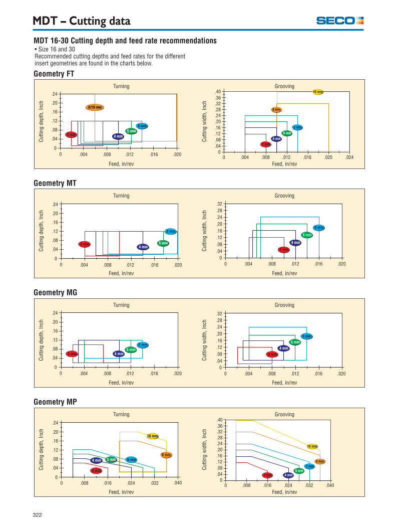
MDT 16-30 Cutting depth and feed rate recommendations
Geometry FT
• Size 16 and 30Recommended cutting depths and feed rates for the differentinsert geometries are found in the charts below.
Cutti
ng d
epth
, Inc
h
Feed, in/rev
Turning
Cutti
ng w
idth
, Inc
h
Feed, in/rev
Grooving
Geometry MT
Cutti
ng d
epth
, Inc
h
Feed, in/rev
Turning
Cutti
ng w
idth
, Inc
h
Feed, in/rev
Grooving
Geometry MG
Cutti
ng d
epth
, Inc
h
Feed, in/rev
Turning
Cutti
ng w
idth
, Inc
h
Feed, in/rev
Grooving
Geometry MP
Cutti
ng d
epth
, Inc
h
Feed, in/rev
Turning
Cutti
ng w
idth
, Inc
h
Feed, in/rev
Grooving

323
���������������
���������
�� ���� ���� ���� ���� ���� ���� ���� ���� ����
���������������
���������
�� ���� ���� ���� ���� ���� ���� ���� ���� ����
���� ���� ���� ���� ����
���
���
���
���
���
���
���� ���� ���� ���� ����
���
���
���
���
���
���
���������������
���������
�� ���� ���� ���� ���� ���� ���� ���� ���� ����
���������������
���������
�� ���� ���� ���� ���� ���� ���� ���� ���� ����
������������������������
����� ���� ���� ���� ���� �����
������������������������
����� ���� ���� ���� ���� �����
MDT 13 – Cutting depth and feed rate recommendations• Size 13Recommended cutting depths and feed rates are found inthe charts below.
Geometry MC
Cutti
ng d
epth
, inc
h
Feed, in/rev
Turning
Cutti
ng w
idth
, inc
h
Feed, in/rev
Grooving
Geometry MCCu
tting
dep
th, i
nch
Feed, in/rev
Turning
Cutti
ng w
idth
, inc
h
Feed, in/rev
Grooving
Geometry MP
Cutti
ng d
epth
, inc
h
Feed, in/rev
Turning
Cutti
ng w
idth
, inc
h
Feed, in/rev
Grooving
Geometry FT
Cutti
ng d
epth
, inc
h
Feed, in/rev
Turning
Cutti
ng w
idth
, inc
h
Feed, in/rev
Grooving
MDT – Cutting data

324
MDT - Cutting data
Classify the workpiece material into a Seco material group to get a cutting speed recommendation based on• workpiece material• insert width and grade• feed rateFor workpiece material classification see page 481-485.
Cutting speed
CP500
4,5–6,03,0–4,0
790690620520
–
690620560480
–
640570490430
–
520480410360
–
460410340330
–
430360330300
–
260250230210
–
590520480430
–
510480410380
–
690620560460390
620560490430390
560510440390360
480390360330310
410340310280250
360330300260230
230210180160
–
520480410360310
480410380330280
920890820790
–
790690640560
–
750690620560
–
740670620570
–
660620560520
–
570510480430
–
430390360340
–
660610560510
–
570520480430
–
850790720670640
690640570510460
670640570510480
670640570520490
620560510480430
510480430390360
390360340330310
610560490430390
520480430380330
8,0–10,0
–670620570520
–570510480410
–570520480430
–590520490460
–490480410390
–430390340330
–340330310300
–490430360310
–410390330300
–––––
–––––
–––––
–––––
–––––
–––––
–––––
–––––
–––––
.004
.008
.012
.016
.020
.004
.008
.012
.016
.020
.004
.008
.012
.016
.020
.004
.008
.012
.016
.020
.004
.008
.012
.016
.020
.004
.008
.012
.016
.020
.004
.008
.012
.016
.020
.004
.008
.012
.016
.020
.004
.008
.012
.016
.020
4,5–6,0
–520490410330
–490430390330
–460410360330
–340330300260
–300260230200
–300250210180
–160150110100
–410360310260
–360330280230
8,0–10,0
CP600
720660570490
–
660570510430
–
590540480410
–
490430390340
–
410360330300
–
410340310260
–
250230210180
–
560490430390
–
480430390360
–
– 3,0–4,0 3,0–10,0
TP200/CP200 883/890
770690620520
–
690620560480
–
640570490430
–
540480410360
–
460410360330
–
430360330300
–
260250230210
–
590520480430
–
510480410380
–
–
TP400
950920870820790
820740660590560
790740660590560
750690620560520
690660590560520
620560510480440
480430410390360
–––––
–––––
3,0–8,0
TK150
1
2
3
4
5
6
7
8
9
SecoMaterial
GroupNo.
Feedf
in/rev
Cutting speed, vc (sf/min)
Insert width, ap (mm)

325
MDT - Cutting data
60
.010–.059
.039–.118
.059–.197
.008–.059
.039–.118
.059–.197
.008–.059
.039–.118
.059–.197
.008–.059
.039–.118
.059–.197
.003 –.008
.004–.010
.008–.016
.004–.010
.006–.012
.008–.016
.004–.010
.006–.012
.008–.016
.004–.010
.006–.012
.008–.016
490380250
–––
–––
–––
460360230
–––
–––
–––
440330210
–––
–––
–––
430310200
–––
–––
–––
390300160
–––
–––
–––
–––
250200150
–––
–––
–––
250180130
–––
–––
–––
210160110
–––
–––
–––
–––
200150110
–––
–––
–––
18013080
–––
–––
–––
–––
1108070
–––
–––
–––
705030
FMR
FMR
FMR
FMR
40–60
21–35
11–20
5 –10
55 50 45 40 35 30 25 20 15 10 5
CP500
4,5–6,03,0–4,0
490430390360
–
310280260230
–
440410340310
–
360330280250210
340310260230
–
340310260230
–
10
11
12
13
14
15
430390330300280
310280260230
–
410360310260250
330300260230210
310260250210180
310260250210180
560490460410
–
–––––
590560510480
–
490460410360
–
430390340310
–
430390340310
–
490460390360310
–––––
560510440410390
460410390340330
390340330300250
390340330300250
8,0–10,0
–410380300260
–––––
–480390340330
–360340330310
–310300280230
–310300280230
–––––
160130110
––
330280260250
–
330280250210
–
300250210160
–
250210160130
–
.004
.008
.012
.016
.020
.004
.008
.012
.016
.020
.004
.008
.012
.016
.020
.004
.008
.012
.016
.020
.004
.008
.012
.016
.020
.004
.008
.012
.016
.020
4,5–6,0
–360300250210
–280260230210
–330260230210
–250230200200
–230210180160
–230210180160
8,0–10,0
CP600
460410380330
–
300260230210
–
–––––
–––––
–––––
–––––
– 3,0–4,0 3,0–8,0
TP200 883/890
490430390360
–
310280260230
–
440410340310
–
360330280250210
340310260230
–
340310260230
–
–
TP400
–––––
–––––
660620570540490
560510480430390
520490430390360
490460410380330
3,0–8,0
TK150Seco
MaterialGroup
No.
Feedf
in/rev
Cutting speed, vc sf/min)
Insert width, ap (mm)
Cutting speed
Machin-ability
%
D.O.Cap(in)
Initial values
Feedf
(in/rev)
Cutting speed, vc (sf/min)
Machinability (%)
Type
of
appl
icat
ion
Cutting data for grade 883 and 890The machinability of the workpiece material expressed in percent is given on page 486.

326
MDT
327
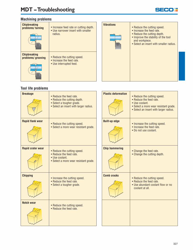
MDT – Troubleshooting
Machining problemsChipbreakingproblems/ turning • Increase feed rate or cutting depth.
• Use narrower insert with smaller radius.
• Reduce the cutting speed.• Increase the feed rate.• Use interrupted feed.
Chipbreakingproblems/ grooving
Vibrations• Reduce the cutting speed.• Increase the feed rate.• Reduce the cutting depth.• Improve the stability of the tool and workpiece.• Select an insert with smaller radius.
Tool life problemsBreakage
• Reduce the feed rate.• Reduce the cutting depth.• Select a tougher grade.• Select an insert with larger radius.
• Reduce the cutting speed.• Select a more wear resistant grade.
Rapid flank wear
Plastic deformation• Reduce the cutting speed.• Reduce the feed rate.• Use coolant.• Select a more wear resistant grade.• Select an insert with larger radius.
• Increase the cutting speed.• Increase the feed rate.• Do not use coolant.
Built-up edge
• Reduce the cutting speed.• Reduce the feed rate.• Use coolant.• Select a more wear resistant grade.
Rapid crater wear• Change the feed rate.• Change the cutting depth.
Chip hammering
• Increase the cutting speed.• Reduce the feed rate.• Select a tougher grade.
Chipping• Reduce the cutting speed.• Reduce the feed rate.• Use abundant coolant flow or no coolant at all.
Comb cracks
• Reduce the cutting speed.• Reduce the feed rate.
Notch wear
328
MDT – Troubleshooting
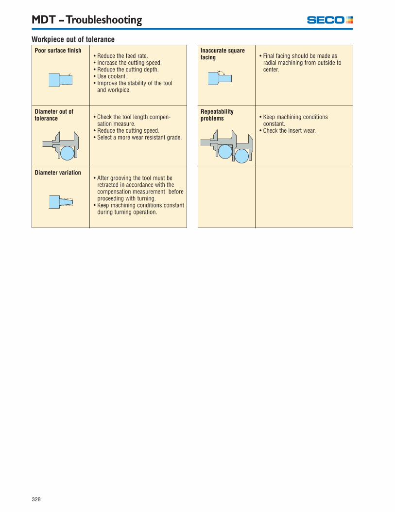
Workpiece out of tolerancePoor surface finish
• Reduce the feed rate.• Increase the cutting speed.• Reduce the cutting depth.• Use coolant.• Improve the stability of the tool and workpice.
• Check the tool length compen- sation measure.• Reduce the cutting speed.• Select a more wear resistant grade.
Diameter out oftolerance
• After grooving the tool must be retracted in accordance with the compensation measurement before proceeding with turning.• Keep machining conditions constant during turning operation.
Diameter variation
Inaccurate square facing • Final facing should be made as
radial machining from outside to center.
• Keep machining conditions constant.• Check the insert wear.
Repeatabilityproblems
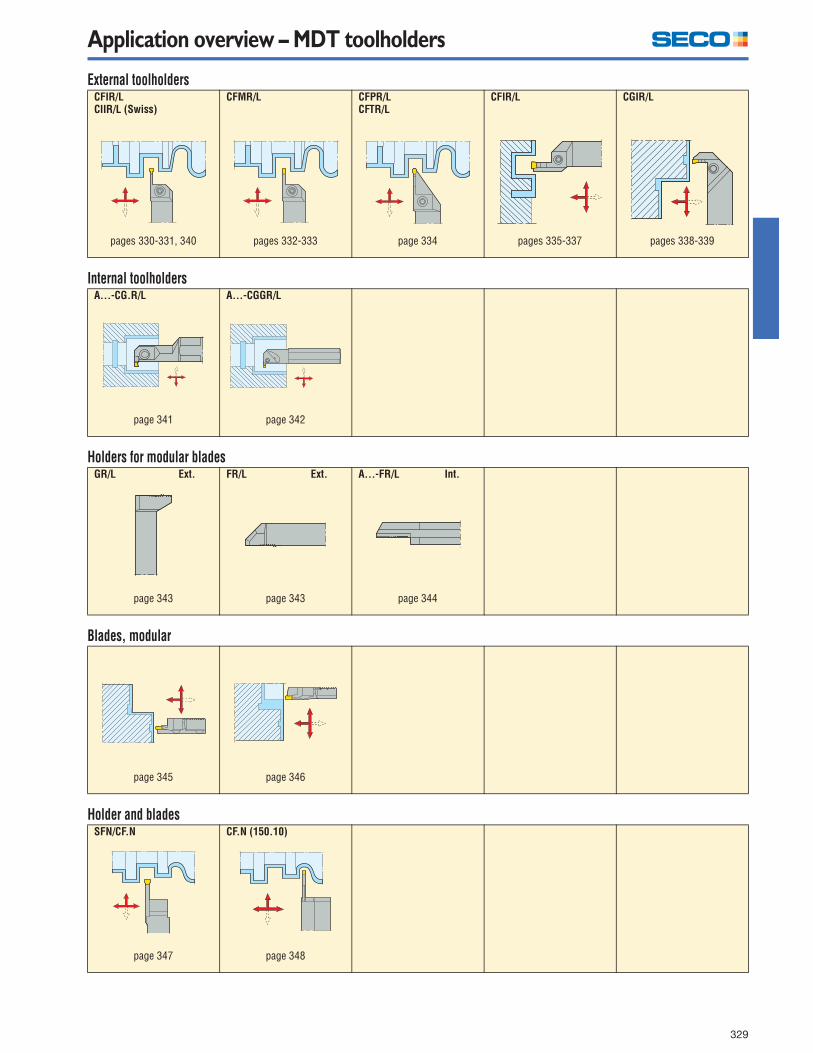
Application overview – MDT toolholders
329
External toolholders
Internal toolholders
Holders for modular blades
Blades, modular
Holder and blades
CFIR/LCIIR/L (Swiss)
CFMR/L CFPR/LCFTR/L
CFIR/L CGIR/L
A...-CG.R/L A...-CGGR/L
GR/L Ext. FR/L Ext. A...-FR/L Int.
SFN/CF.N CF.N (150.10)
pages 330-331, 340 pages 332-333 page 334 pages 335-337 pages 338-339
page 341 page 342
page 343 page 343 page 344
page 345 page 346
page 347 page 348
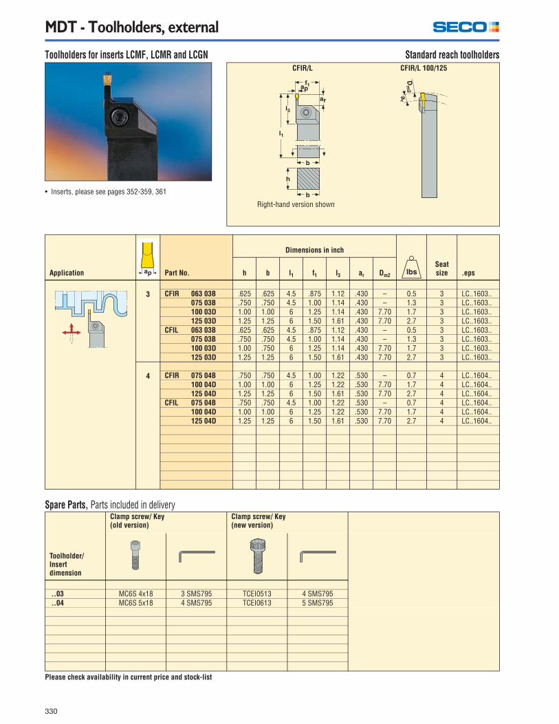
MDT - Toolholders, external
330
Toolholders for inserts LCMF, LCMR and LCGN Standard reach toolholders
Spare Parts, Parts included in delivery
Please check availability in current price and stock-list
Application Part No.
Dimensions in inch
Seatsize .epsh b l1 f1 l3 ar Dm2
3 CFIR 063 03B .625 .625 4.5 .875 1.12 .430 – 0.5 3 LC..1603.. 075 03B .750 .750 4.5 1.00 1.14 .430 – 1.3 3 LC..1603.. 100 03D 1.00 1.00 6 1.25 1.14 .430 7.70 1.7 3 LC..1603.. 125 03D 1.25 1.25 6 1.50 1.61 .430 7.70 2.7 3 LC..1603..
CFIL 063 03B .625 .625 4.5 .875 1.12 .430 – 0.5 3 LC..1603.. 075 03B .750 .750 4.5 1.00 1.14 .430 – 1.3 3 LC..1603.. 100 03D 1.00 .750 6 1.25 1.14 .430 7.70 1.7 3 LC..1603.. 125 03D 1.25 1.25 6 1.50 1.61 .430 7.70 2.7 3 LC..1603..
4 CFIR 075 04B .750 .750 4.5 1.00 1.22 .530 – 0.7 4 LC..1604.. 100 04D 1.00 1.00 6 1.25 1.22 .530 7.70 1.7 4 LC..1604.. 125 04D 1.25 1.25 6 1.50 1.61 .530 7.70 2.7 4 LC..1604..
CFIL 075 04B .750 .750 4.5 1.00 1.22 .530 – 0.7 4 LC..1604.. 100 04D 1.00 1.00 6 1.25 1.22 .530 7.70 1.7 4 LC..1604.. 125 04D 1.25 1.25 6 1.50 1.61 .530 7.70 2.7 4 LC..1604..
Toolholder/Insertdimension
Clamp screw/ Key(old version)
Clamp screw/ Key(new version)
..03 MC6S 4x18 3 SMS795 TCEI0513 4 SMS795 ..04 MC6S 5x18 4 SMS795 TCEI0613 5 SMS795
• Inserts, please see pages 352-359, 361
CFIR/L CFIR/L 100/125
Right-hand version shown

MDT - Toolholders, external
331
Toolholders for inserts LCMF, LCMR and LCGN Standard reach toolholders
*Max depth of cut for LCMF16.. = .550 in., LCMF30.. = 1.100 in.
Spare Parts, Parts included in delivery
Please check availability in current price and stock-list
Application Part No.
Dimensions in inch
Seatsizeh b l1 f1 l3 ar* Dm2
5 CFIR 075 05B .750 .750 4.5 1.00 1.42 .610 – 0.7 5 LC..1605.. 100 05D 1.00 1.00 6 1.25 1.42 .610 7.70 1.7 5 LC..1605.. 125 05D 1.25 1.25 6 1.50 1.61 .610 7.70 2.7 5 LC..1605..
CFIL 075 05B .750 .750 4.5 1.00 1.42 .610 – 0.7 5 LC..1605.. 100 05D 1.00 1.00 6 1.25 1.42 .610 7.70 1.7 5 LC..1605.. 125 05D 1.25 1.25. 6 1.25 1.61 .610 7.70 2.7 5 LC..1605..
6 CFIR 100 06D 1.00 1.00 6 1.25 1.61 .800 7.70 1.7 6 LC..1606.. 125 06D 1.25 1.25 6 1.50 1.61 .800 7.70 2.7 6 LC..1606..
CFIL 100 06D 1.00 1.00 6 1.25 1.61 .800 7.70 1.7 6 LC..1606.. 125 06D 1.25 1.25 6 1.50 1.61 .800 7.70 2.7 6 LC..1606..
8 CFIR 100 08D 1.00 1.00 6 1.25 1.98 1.00 7.70 1.7 8 LC..3008.. 125 08E 1.25 1.25 7 1.50 1.98 1.00 7.70 2.7 8 LC..3008..
CFIL 100 08D 1.00 1.00 6 1.25 1.98 1.00 7.70 1.7 8 LC..3008.. 125 08E 1.25 1.25 7 1.50 1.98 1.00 7.70 3.0 8 LC..3008..
Toolholder/Insertdimension
Clamp screw/ Key(old version)
Clamp screw/ Key(new version)
..05 MC6S 5x18 4 SMS795 TCEI0613 5 SMS795
..06 MC6S 6x20 5 SMS795 TCEI0815 6 SMS795
..08 TCEI 0825 6 SMS795 TCEI1020 6 SMS795
• Inserts, please see pages 352-358, 361
CFIR/L CFIR/L 100/125
Right-hand version shown

MDT - Toolholders, external
332
Toolholders for inserts LCMF, LCMR and LCGN Long reach toolholders
*Max depth of cut for LCMF16.. = .550 in.
Spare Parts, Parts included in delivery
Please check availability in current price and stock-list
Application Part No.
Dimensions in inch
Seatsizeh b l1 f1 l3 ar* Dm2
3 CFMR 075 03B .750 .750 4.5 1.00 1.14 .680 7.70 0.7 3 LC..1603.. 100 03D 1.00 1.00 6 1.25 1.44 .680 7.70 1.4 3 LC..1603.. 125 03D 1.25 1.25 6 1.50 1.14 .680 7.70 2.2 3 LC..1603.. 150 03E 1.50 1.50 7 2.00 1.62 .680 7.70 3.6 3 LC..1603..
CFML 075 03B .750 .750 4.5 1.00 1.14 .680 7.70 0.7 3 LC..1603.. 100 03D 1.00 1.00 6 1.25 1.44 .680 7.70 1.4 3 LC..1603.. 125 03D 1.25 1.25 6 1.50 1.14 .680 7.70 2.2 3 LC..1603.. 150 03E 1.50 1.50 7 2.00 1.62 .680 7.70 3.6 3 LC..1603..
4 CFMR 075 04B .750 .750 4.5 1.00 1.22 .787 7.70 0.7 4 LC..1604.. 100 04D 1.00 1.00 6 1.25 1.54 .787 7.70 1.4 4 LC..1604.. 125 04D 1.25 1.25 6 1.50 1.22 .787 7.70 2.2 4 LC..1604.. 150 04E 1.50 1.50 7 2.00 1.97 .787 7.70 3.6 4 LC..1604..
CFML 075 04B .750 .750 4.5 1.00 1.22 .787 7.70 0.7 4 LC..1604.. 100 04D 1.00 1.00 6 1.25 1.54 .787 7.70 1.4 4 LC..1604.. 125 04D 1.25 1.25 6 1.50 1.22 .787 7.70 2.2 4 LC..1604.. 150 04E 1.50 1.50 7 2.00 1.97 .787 7.70 3.6 4 LC..1604..
Toolholder/Insertdimension
Clamp screw/ Key(old version)
Clamp screw/ Key(new version)
..03 MC6S 4x18 3 SMS795 TCEI0513 4 SMS795
..04 MC6S 5x18 4 SMS795 TCEI0613 5 SMS795
• Inserts, please see pages 352-359, 361
CFMR/L CFIR/L 100/125/150
Right-hand version shown

MDT - Toolholders, external
333
Toolholders for inserts LCMF, LCMR and LCGN Long reach toolholders
*Max depth of cut for LCMF16.. = .550 in., LCMF30.. = 1.100 in.
Spare Parts, Parts included in delivery
Please check availability in current price and stock-list
Application Part No.
Dimensions in inch
Seatsizeh b l1 f1 l3 ar* Dm2
5 CFMR 100 05D 1.00 1.00 6 1.25 1.70 .984 7.70 1.5 5 LC..1605.. 125 05D 1.25 1.25 6 1.50 1.42 .984 7.70 2.2 5 LC..1605.. 150 05E 1.50 1.50 7 2.00 2.25 .984 7.70 3.6 5 LC..1605..
CFML 100 05D 1.00 1.00 6 1.25 1.70 .984 7.70 1.5 5 LC..1605.. 125 05D 1.25 1.25 6 1.50 1.42 .984 7.70 2.2 5 LC..1605.. 150 05E 1.50 1.50 7 2.00 2.25 .984 7.70 3.6 5 LC..1605..
6 CFMR 100 06D 1.00 1.00 6 1.25 2.05 1.300 7.70 1.5 6 LC..1606.. 125 06D 1.25 1.25 6 1.50 1.61 1.300 7.70 2.3 6 LC..1606.. 150 06E 1.50 1.50 7 2.00 2.61 1.300 7.70 3.6 6 LC..1606..
CFML 100 06D 1.00 1.00 6 1.25 2.05 1.300 7.70 1.5 6 LC..1606.. 125 06D 1.25 1.25 6 1.50 1.61 1.300 7.70 2.3 6 LC..1606.. 150 06E 1.50 1.50 7 2.00 2.61 1.300 7.70 3.6 6 LC..1606..
8 CFMR 100 08D 1.00 1.00 6 1.25 1.98 1.620 7.70 1.5 8 LC..3008.. 125 08E 1.25 1.25 7 1.50 1.98 1.620 7.70 2.3 8 LC..3008.. 150 08E 1.50 1.50 7 2.00 3.28 1.620 7.70 3.6 8 LC..3008..
CFML 100 08D 1.00 1.00 6 1.125 1.98 1.620 7.70 1.5 8 LC..3008.. 125 08E 1.25 1.25 7 1.50 1.98 1.620 7.70 2.3 8 LC..3008.. 150 08E 1.50 1.50 7 2.00 3.28 1.620 7.70 3.6 8 LC..3008..
Toolholder/Insertdimension
Clamp screw/ Key(old version)
Clamp screw/ Key(new version)
..05 MC6S 5x18 4 SMS795 TCEI0613 5 SMS795
..06 MC6S 6x20 5 SMS795 TCEI0815 6 SMS795
..08 TCEI 0825 6 SMS795 TCEI1020 6 SMS795
• Inserts, please see pages 352-358, 361
CFMR/L CFIR/L 100/125/150
Right-hand version shown

MDT - Toolholders, external
334
Toolholders for inserts LCMR Deep grooving/Cut-off toolholders
*Due to the design, grooving depth is limited.
Spare Parts, Parts included in delivery
Please check availability in current price and stock-list
Application Part No.
Dimensions in inch
Seatsizeh b l1 f1 l3
∅max*
3 CFTR 075 03C .75 .75 5.00 1.00 1.65 2.00 .88 3 LC..1603..CFTR 100 03D 1.00 1.00 6.00 1.25 1.65 2.00 1.54 3 LC..1603..CFTL 075 03C .75 .75 5.00 1.00 1.65 2.00 .88 3 LC..1603..CFTL 100 03D 1.00 1.00 6.00 1.25 1.65 2.00 1.54 3 LC..1603..
4 CFPR 075 04C .75 .75 5.00 1.00 1.65 2.00 .88 4 LC..1604..CFPR 100 04D 1.00 1.00 6.00 1.25 1.65 2.00 1.54 4 LC..1604..CFPL 075 04C .75 .75 5.00 1.00 1.65 2.00 .88 4 LC..1604..CFPL 100 04D 1.00 1.00 6.00 1.25 1.65 2.00 1.54 4 LC..1604..
Toolholder/Insertdimension
Clamp screw Key
CFT.. TCEI0513 4 SMS795CFP.. TCEI0613 5 SMS795
• Inserts, please see pages 352-359, 361
CFTR/L, CFPR/L
* ∅ maxRight-hand version shown

MDT - Toolholders, external
335
Toolholders for inserts LCMF, LCMR and LCGN Face machining toolholders
*Initial plunge relates to face groove diameter
Spare Parts, Parts included in delivery
Please check availability in current price and stock-list
ApplicationInitial
plunge* Part No.
Dimensions in inch
Seatsizeh b l1 f1 l3 ar
3 4.00/2.75 CFIR 100 03D-L4.00 2.75 1.00 1.00 6 1.25 1.10 .430 1.7 3 LC..1603..5.00/3.50 100 03D-L5.00 3.50 1.00 1.00 6 1.25 1.10 .430 1.7 3 LC..1603..6.70/4.30 100 03D-L6.70 4.30 1.00 1.00 6 1.25 1.10 .430 1.7 3 LC..1603..4.00/2.75 CFIL 100 03D-R4.00 2.75 1.00 1.00 6 1.25 1.10 .430 1.7 3 LC..1603..5.00/3.50 100 03D-R5.00 3.50 1.00 1.00 6 1.25 1.10 .430 1.7 3 LC..1603..6.70/4.30 100 03D-R6.70 4.30 1.00 1.00 6 1.25 1.10 .430 1.7 3 LC..1603..
4 4.00/2.75 CFIR 100 04D-L4.00 2.75 1.00 1.00 6 1.25 1.22 .530 1.7 4 LC..1604..5.00/3.50 100 04D-L5.00 3.50 1.00 1.00 6 1.25 1.22 .530 1.7 4 LC..1604..9.00/5.50 100 04D-L9.00 5.50 1.00 1.00 6 1.25 1.22 .530 1.7 4 LC..1604..4.00/2.75 CFIL 100 04D-R4.00 2.75 1.00 1.00 6 1.25 1.22 .530 1.7 4 LC..1604..5.00/3.50 100 04D-R5.00 3.50 1.00 1.00 6 1.25 1.22 .530 1.7 4 LC..1604..9.00/5.50 100 04D-R9.00 5.50 1.00 1.00 6 1.25 1.22 .530 1.7 4 LC..1604..
Toolholder/Insertdimension
Clamp screw/ Key(old version)
Clamp screw/ Key(new version)
..03 MC6S 4x18 3 SMS795 TCEI0513 4 SMS795
..04 MC6S 5x18 4 SMS795 TCEI0613 5 SMS795
• Inserts, please see pages 352-359, 361
CFIR/L
Initial plunge range e.g. 4.00/2.75 (4.00 inch/2.75)Right-hand version with left-hand blade shown

MDT - Toolholders, external
336
Toolholders for inserts LCMF, LCMR and LCGN Face machining toolholders
*Initial plunge relates to face groove diameter
Spare Parts, Parts included in delivery
Please check availability in current price and stock-list
ApplicationInitial
plunge* Part No.
Dimensions in inch
Seatsizeh b l1 f1 l3 ar*
5 4.00/2.75 CFIR 100 05D-L4.00 2.75 1.00 1.00 6 1.25 1.42 .610 1.7 5 LC..1605..5.00/3.50 100 05D-L5.00 3.50 1.00 1.00 6 1.25 1.42 .610 1.7 5 LC..1605..6.70/4.30 100 05D-L6.70 4.30 1.00 1.00 6 1.25 1.42 .610 1.7 5 LC..1605..9.00/5.50 100 05D-L9.00 5.50 1.00 1.00 6 1.25 1.42 .610 1.7 5 LC..1605..4.00/2.75 CFIL 100 05D-R4.00 2.75 1.00 1.00 6 1.25 1.42 .610 1.7 5 LC..1605..5.00/3.50 100 05D-R5.00 3.50 1.00 1.00 6 1.25 1.42 .610 1.7 5 LC..1605..6.70/4.30 100 05D-R6.70 4.30 1.00 1.00 6 1.25 1.42 .610 1.7 5 LC..1605..9.00/5.50 100 05D-R9.00 5.50 1.00 1.00 6 1.25 1.42 .610 1.7 5 LC..1605..
6 4.00/2.75 CFIR 100 06D-L4.00 2.75 1.00 1.00 6 1.25 1.57 .800 1.7 6 LC..1606..5.00/3.50 100 06D-L5.00 3.50 1.00 1.00 6 1.25 1.57 .800 1.7 6 LC..1606..6.70/4.30 100 06D-L6.70 4.30 1.00 1.00 6 1.25 1.57 .800 1.7 6 LC..1606..9.00/5.50 100 06D-L9.00 5.50 1.00 1.00 6 1.25 1.57 .800 1.7 6 LC..1606..4.00/2.75 CFIL 100 06D-R4.00 2.75 1.00 1.00 6 1.25 1.57 .800 1.7 6 LC..1606..5.00/3.50 100 06D-R5.00 3.50 1.00 1.00 6 1.25 1.57 .800 1.7 6 LC..1606..6.70/4.30 100 06D-R6.70 4.30 1.00 1.00 6 1.25 1.57 .800 1.7 6 LC..1606..9.00/5.50 100 06D-R9.00 5.50 1.00 1.00 6 1.25 1.57 .800 1.7 6 LC..1606..
Toolholder/Insertdimension
Clamp screw/ Key(old version)
Clamp screw/ Key(new version)
..05 MC6S 5x18 4 SMS795 TCEI0613 5 SMS795
..06 MC6S 6x20 5 SMS795 TCEI0815 6 SMS795
• Inserts, please see pages 352-358, 361
CFIR/L
Initial plunge range e.g. 4.00/2.75 (4.00 inch/2.75)Right-hand version with left-hand blade shown

MDT - Toolholders, external
337
Toolholders for inserts LCMF, LCMR and LCGN Face machining toolholders
*Initial plunge relates to face groove diameter
Spare Parts, Parts included in delivery
Please check availability in current price and stock-list
ApplicationInitial
plunge* Part No.
Dimensions in inch
Seatsizeh b l1 f1 l3 ar*
8 5.00/3.50 CFIR 100 08D-L5.00 3.50 1.00 1.00 6 1.25 2.06 1.00 1.7 8 LC..3008..6.70/4.30 100 08D-L6.70 4.30 1.00 1.00 6 1.25 2.06 1.00 1.7 8 LC..3008..9.00/5.50 100 08D-L9.00 5.50 1.00 1.00 6 1.25 2.06 1.00 1.7 8 LC..3008..19.7/8.00 100 08D-L19.7 8.00 1.00 1.00 6 1.25 2.06 1.00 1.7 8 LC..3008..5.00/3.50 CFIL 100 08D-R5.00 3.50 1.00 1.00 6 1.25 2.06 1.00 1.7 8 LC..3008..6.70/4.30 100 08D-R6.70 4.30 1.00 1.00 6 1.25 2.06 1.00 1.7 8 LC..3008..9.00/5.50 100 08D-R9.00 5.50 1.00 1.00 6 1.25 2.06 1.00 1.7 8 LC..3008..19.7/8.00 100 08D-R19.7 8.00 1.00 1.00 6 1.25 2.06 1.00 1.7 8 LC..3008..
Toolholder/Insertdimension
Clamp screw/ Key(old version)
Clamp screw/ Key(new version)
..08 MC6S 6x20 5 SMS795 TCEI0815 6 SMS795
• Inserts, please see pages 352-354
CFIR/L
Initial plunge range e.g. 4.00/2.75 (4.00 inch/2.75)Right-hand version with left-hand blade shown

MDT - Toolholders, external
338
Toolholders for inserts LCMF, LCMR and LCGN Face machining toolholders
*Initial plunge relates to face groove diameter
Spare Parts, Parts included in delivery
Please check availability in current price and stock-list
ApplicationInitial
plunge* Part No.
Dimensions in inch
Seatsizeh b l1 f1 l3 ar*
3 4.00/2.75 CGIR 100 03D-R4.00 2.75 1.00 1.00 6.00 1.42 1.26 .430 1.5 3 LC..1603..5.00/3.50 100 03D-R5.00 3.50 1.00 1.00 6.00 1.42 1.26 .430 1.5 3 LC..1603..4.00/2.75 CGIL 100 03D-L4.00 2.75 1.00 1.00 6.00 1.42 1.26 .430 1.5 3 LC..1603..5.00/3.50 100 03D-L5.00 3.50 1.00 1.00 6.00 1.42 1.26 .430 1.5 3 LC..1603..
4 4.00/2.75 CGIR 100 04D-R4.00 2.75 1.00 1.00 6.00 1.51 1.26 .530 1.5 4 LC..1604..5.00/3.50 100 04D-R5.00 3.50 1.00 1.00 6.00 1.51 1.26 .530 1.5 4 LC..1604..4.00/2.75 CGIL 100 04D-L4.00 2.75 1.00 1.00 6.00 1.51 1.26 .530 1.5 4 LC..1604..5.00/3.50 100 04D-L5.00 3.50 1.00 1.00 6.00 1.51 1.26 .530 1.5 4 LC..1604..
Toolholder/Insertdimension
Clamp screw/ Key(old version)
Clamp screw/ Key(new version)
..03 MC6S 4x18 3 SMS795 TCEI0513 4 SMS795
..04 MC6S 5x18 4 SMS795 TCEI0613 5 SMS795
• Inserts, please see pages 352-359, 361
CGIR/L
Initial plunge range e.g. 4.00/2.75 (4.00 inch/2.75)Right-hand version with right-hand blade shown

MDT - Toolholders, external
339
Toolholders for inserts LCMF, LCMR and LCGN Face machining toolholders
*Initial plunge relates to face groove diameter
Spare Parts, Parts included in delivery
Please check availability in current price and stock-list
ApplicationInitial
plunge* Part No.
Dimensions in inch
Seatsizeh b l1 f1 l3 ar*
6 5.00/3.50 CGIR 100 06D-R5.00 3.50 1.00 1.00 6.00 1.79 1.26 .800 1.5 6 LC..1606..6.70/4.30 100 06D-R6.70 4.30 1.00 1.00 6.00 1.79 1.26 .800 1.5 6 LC..1606..9.00/5.50 100 06D-R9.00 5.50 1.00 1.00 6.00 1.79 1.26 .800 1.5 6 LC..1606..5.00/3.50 CGIL 100 06D-L5.00 3.50 1.00 1.00 6.00 1.79 1.26 .800 1.5 6 LC..1606..6.70/4.30 100 06D-L6.70 4.30 1.00 1.00 6.00 1.79 1.26 .800 1.5 6 LC..1606..9.00/5.50 100 06D-L9.00 5.50 1.00 1.00 6.00 1.79 1.26 .800 1.5 6 LC..1606..
8 5.00/3.50 CGIR 100 08D-R5.00 3.50 1.00 1.00 6.00 2.00 1.26 1.0 1.5 6 LC..3008..6.70/4.30 100 08D-R6.70 4.30 1.00 1.00 6.00 2.00 1.26 1.0 1.5 6 LC..3008..9.00/5.50 100 08D-R9.00 5.50 1.00 1.00 6.00 2.00 1.26 1.0 1.5 6 LC..3008..19.7/8.00 100 08D-R19.7 8.00 1.00 1.00 6.00 2.00 1.26 1.0 1.5 6 LC..3008..5.00/3.50 CGIL 100 08D-L5.00 3.50 1.00 1.00 6.00 2.00 1.26 1.0 1.5 6 LC..3008..6.70/4.30 100 08D-L6.70 4.30 1.00 1.00 6.00 2.00 1.26 1.0 1.5 6 LC..3008..9.00/5.50 100 08D-L9.00 5.50 1.00 1.00 6.00 2.00 1.26 1.0 1.5 6 LC..3008..19.7/8.00 100 08D-L19.7 8.00 1.00 1.00 6.00 2.00 1.26 1.0 1.5 6 LC..3008..
Toolholder/Insertdimension
Clamp screw/ Key(old version)
Clamp screw/ Key(new version)
..06 MC6S 6x20 5 SMS795 TCEI0815 6 SMS795
..08 TCEI0825 6 SMS795 TCEI1020 6 SMS795
• Inserts, please see pages 352-356, 358, 361
CGIR/L
Initial plunge range e.g. 4.00/2.75 (4.00 inch/2.75)Right-hand version with right-hand blade shown

MDT - Toolholders, external
340
Toolholders for inserts LCMF, LCMR and LCGN Swiss toolholders
*Max depth of cut fpr LCMF16.. = .550 in.
Spare Parts, Parts included in delivery
Please check availability in current price and stock-list
Application Part No.
Dimensions in inch
Seatsizeh b l1 f1 ar*
3 CIIR 050 03D .500 .500 6 .500 .430 .4 3 LC..1603.. 0625 03B .625 .625 4.5 .625 .430 .5 3 LC..1603..
CIIL 050 03D .500 .500 6 .500 .430 .4 3 LC..1603.. 0625 03B .625 .625 4.5 .625 .430 .5 3 LC..1603..
Toolholder/Insertdimension
Clamp screw/ Key(old version)
Clamp screw/ Key(new version)
050 03D MC6S 4x18 3 SMS795 TCEI0513 4 SMS7950625 03B MC6S 4x18 3 SMS795 TCEI0613 5 SMS795
• Inserts, please see pages 352-359, 361
CIIR/L
Right-hand version shown

MDT - Toolholders, internal
341
Toolholders for inserts LCMF and LCMR
Spare Parts, Parts included in delivery
Please check availability in current price and stock-list *To be ordered separately
Application Part No.
Dimensions in inch
Seatsizedmm l1 l3 l4 f1 ar
∅min
03 A10-CGER 1303 .625 7.00 1.62 .98 .40 .118 .630 .44 3 LC..1303..A10-CGEL 1303 .625 7.00 1.62 .98 .40 .118 .630 .44 3 LC..1303..
A12-CGFR 1303 .75 8.00 2.01 1.18 .57 .216 .790 .88 3 LC..1303..A12-CGFL 1303 .75 8.00 2.01 1.18 .57 .216 .790 .88 3 LC..1303..
A16-CGHR 1303 1.00 10.00 2.60 1.57 .75 .295 .985 1.54 3 LC..1303..A16-CGHL 1303 1.00 10.00 2.60 1.57 .75 .295 .985 1.54 3 LC..1303..
A20-CGJR 1303 1.25 12.00 3.09 1.97 1.00 .413 1.26 3.3 3 LC..1303..A20-CGJL 1303 1.25 12.00 3.09 1.97 1.00 .413 1.26 3.3 3 LC..1303..
04 A12-CGFR 1304 .75 8.00 2.01 1.18 .57 .216 .790 .88 4 LC..1304..A12-CGFL 1304 .75 8.00 2.01 1.18 .57 .216 .790 .88 4 LC..1304..
A16-CGFR 1304 1.00 10.00 2.60 1.57 .75 .295 .985 1.54 4 LC..1304..A16-CGFL 1304 1.00 10.00 2.60 1.57 .75 .295 .985 1.54 4 LC..1304..
A20-CGHR 1304 1.25 12.00 3.09 1.97 1.00 .413 1.26 3.3 4 LC..1304..A20-CGHL 1304 1.25 12.00 3.09 1.97 1.00 .413 1.26 3.3 4 LC..1304..
Toolholder/Insertdimension
Clamp screw Key Coolantadaptor*
A10-.. L85011-T15P T15P-7 SEAL16A12-.. L85011-T15P T15P-7 SEAL20A16-.. L85011-T15P T15P-7 SEAL25A20-.. L85011-T15P T15P-7 SEAL32
• Inserts, please see pages 349-351, 360
CG.R/L
Right-hand version shown

MDT - Toolholders, internal
342
Toolholders for inserts LCGN, LCMF and LCMR
Spare Parts, Parts included in delivery
Please check availability in current price and stock-list *To be ordered separately
Application Part No.
Dimensions in inch
Seatsizedmm l1 l3 f1 ar
∅min
03 A24-CGGR 03 1.50 12 2.36 1.125 .440 1.80 5.5 3 LC..1603..A24-CGGL 03 1.50 12 2.36 1.125 .440 1.80 5.5 3 LC..1603..
04 A24-CGGR 04 1.50 12 2.36 1.125 .440 1.80 5.5 4 LC..1604..A24-CGGL 04 1.50 12 2.36 1.125 .440 1.80 5.5 4 LC..1604..
05 A24-CGGR 05 1.50 12 2.36 1.091 .440 1.80 5.5 5 LC..1605..A24-CGGL 05 1.50 12 2.36 1.091 .440 1.80 5.5 5 LC..1605..
06 A24-CGGR 06 1.50 12 2.36 1.130 .515 1.80 5.5 6 LC..1606..A24-CGGL 06 1.50 12 2.36 1.130 .515 1.80 5.5 6 LC..1606..
Toolholder/Insertdimension
Clamp screw Key Coolantadaptor*
A24T-...03 MC6S 4x14 3 SMS795 SEAL40A24T-...04 MC6S 5x14 4 SMS795 SEAL40A24T-...05 MC6S 5x14 4 SMS795 SEAL40A24T-...06 TCEI0614 5 SMS795 SEAL40
• Inserts, please see pages 352-359, 361
CGGR/L
Right-hand version shown

MDT - Holders, external for modular holders
343
Toolholders
Please check availability in current price and stock-list
Application Part No.
Dimensions in inch
h b l1 f1 l3
GR063B-V21 .63 .63 4.5 .63 .630 .44GL063B-V21 .63 .63 4.5 .63 .630 .44GR075B-V21 .75 .75 4.5 .75 .630 .88GL075B-V21 .75 .75 4.5 .75 .630 .88GR100D-V21 1.00 1.00 6.00 1.00 .630 1.76GL100D-V21 1.00 1.00 6.00 1.00 .630 1.76GR125D-V21 1.25 1.25 6.00 1.25 .630 2.43GL125D-V21 1.25 1.25 6.00 1.25 .630 2.43
FR063B-V21 .63 .63 4.5 .67 1.33 .44FL063B-V21 .63 .63 4.5 .67 1.33 .44FR075B-V21 .75 .75 4.5 .80 1.33 .88FL075B-V21 .75 .75 4.5 .80 1.33 .88FR100D-V21 1.00 1.00 6.00 1.05 1.33 1.54FL100D-V21 1.00 1.00 6.00 1.05 1.33 1.54FR125D-V21 1.25 1.25 6.00 1.60 1.33 2.43FL125D-V21 1.25 1.25 6.00 1.60 1.33 2.43
Toolholder/Insertdimension
Locking screw Screw Key
..-V21 C46017-T20P F85015-T20P T20P-7L
• Blades, please see pages 345-346• How to assemble, see pages 318-319• Note that in photo above, tool GR/L is shown on the left and tool FR/L is shown on the right.
GR/L FR/L
Right-hand version shown

MDT - Holders, internal for modular holders
344
Toolholders
Please check availability in current price and stock-list
Application Part No.
Dimensions in inch
dmm l1 l3 f1
A16-FR-V21 1.00 8 1.81 .170 1.32A16-FL-V21 1.00 8 1.81 .170 1.32A20-FR-V21 1.25 10 1.77 .294 2.87A20-FL-V21 1.25 10 1.77 .294 2.87A24-FR-V21 1.50 12 1.77 .420 5.29A24-FL-V21 1.50 12 1.77 .420 5.29
Toolholder/Insertdimension
Locking screw Screw Key Coolantadaptor*
A16- C46017-T20P F85015-T20P T20P-7L SEAL25A20- C46017-T20P F85015-T20P T20P-7L SEAL32A24- C46017-T20P F85015-T20P T20P-7L SEAL40
• Blades, please see pages 345-346• How to assemble, see pages 318-319
FR/L
Right-hand version shown

MDT - Blades, modular
345
Blades
Please check availability in current price and stock-list
ApplicationInitial
plunge* Part No. Inch Part No. Metric
Dimensions in inch
l1 f1 ar
3 1.18/.670 V21-CJR 1303L1.18-.670 1303L030017 .413 .362 .374 .09 LC..1303..1.54/.950 1303L1.54-.950 1303L039024 .413 .362 .374 .11 LC..1303..1.97/1.30 V21-CKR 1303L1.97-1.30 1303L050033 .472 .362 .433 .13 LC..1303..2.36/1.70 1303L2.36-1.70 1303L060043 .472 .362 .433 .13 LC..1303..3.00/2.09 1303L3.00-2.09 1303L076053 .472 .362 .433 .15 LC..1303..1.18/.670 V21-CJL 1303R1.18-.670 1303R030017 .413 .362 .374 .09 LC..1303..1.54/.950 1303R1.54-.950 1303R039024 .413 .362 .374 .11 LC..1303..1.97/1.30 V21-CKL 1303R1.97-1.30 1303R050033 .472 .362 .433 .13 LC..1303..2.36/1.70 1303R2.36-1.70 1303R060043 .472 .362 .433 .13 LC..1303..3.00/2.09 1303R3.00-2.09 1303R076053 .472 .362 .433 .15 LC..1303..
4 1.18/.670 V21-CHR 1304L1.18-.670 1304L030017 .413 .362 .374 .09 LC..1304..1.34/.826 1304L1.34-.826 1304L034021 .413 .362 .374 .11 LC..1304..1.57/1.02 V21-CIR 1304L1.57-1.02 1304L040026 .472 .362 .433 .13 LC..1304..1.97/1.26 1304L1.97-1.26 1304L050032 .472 .362 .433 .13 LC..1304..2.36/1.65 1304L2.36-1.65 1304L060042 .472 .362 .433 .13 LC..1304..2.96/2.05 1304L2.96-2.05 1304L075052 .472 .362 .433 .15 LC..1304..3.94/2.64 1304L3.94-2.64 1304L100067 .472 .362 .433 .18 LC..1304..1.18/.670 V21-CHL 1304R1.18-.670 1304R030017 .413 .362 .374 .09 LC..1304..1.34/.826 1304R1.34-.826 1304R030421 .413 .362 .374 .11 LC..1304..1.57/1.02 V21-CIL 1304R1.57-1.02 1304R040026 .472 .362 .433 .13 LC..1304..1.97/1.26 1304R1.97-1.26 1304R050032 .472 .362 .433 .13 LC..1304..2.36/1.65 1304R2.36-1.65 1304R060042 .472 .362 .433 .13 LC..1304..2.96/2.05 1304R2.96-2.05 1304R075052 .472 .362 .433 .15 LC..1304..3.94/2.64 1304R3.94-2.64 1304R100067 .472 .362 .433 .18 LC..1304..
• Holders, please see pages 343-344• How to assemble, see pages 318-319• Inserts, please see pages 349-351, 360
C.R/L
Initial plunge range e.g. 1.18-.670 (1.18 inch/.670 inch)Right-hand version with left-hand blade shown

MDT - Blades, modular
346
Blades
Please check availability in current price and stock-list
ApplicationInitial
plunge* Part No. Part No. Metric
Dimensions in inch
l1 f1 ar
3 1.18/.670 V21-CJR 1303R1.18-.670 1303R030017 .413 .362 .374 .09 LC..1303..1.54/.950 1303R1.54-.950 1303R039024 .413 .362 .374 .11 LC..1303..1.97/1.30 V21-CKR 1303R1.97-1.30 1303R050033 .472 .362 .433 .13 LC..1303..2.36/1.70 1303R2.36-1.70 1303R060043 .472 .362 .433 .13 LC..1303..3.00/2.09 1303R3.00-2.09 1303R076053 .472 .362 .433 .15 LC..1303..1.18/.670 V21-CJL 1303L1.18-.670 1303L030017 .413 .362 .374 .09 LC..1303..1.54/.950 1303L1.54-.950 1303L039024 .413 .362 .374 .11 LC..1303..1.97/1.30 V21-CKL 1303L1.97-1.30 1303L050033 .472 .362 .433 .13 LC..1303..2.36/1.70 1303L2.36-1.70 1303L060043 .472 .362 .433 .13 LC..1303..3.00/2.09 1303L3.00-2.09 1303L076053 .472 .362 .433 .15 LC..1303..
4 1.18/.670 V21-CHR 1304R1.18-.670 1304R030017 .413 .362 .374 .09 LC..1304..1.34/.826 1304R1.34-.826 1304R034021 .413 .362 .374 .11 LC..1304..1.57/1.02 V21-CIR 1304R1.57-1.02 1304R040026 .472 .362 .433 .13 LC..1304..1.97/1.26 1304R1.97-1.26 1304R050032 .472 .362 .433 .13 LC..1304..2.36/1.65 1304R2.36-1.65 1304R060042 .472 .362 .433 .13 LC..1304..2.96/2.05 1304R2.96-2.05 1304R075052 .472 .362 .433 .15 LC..1304..3.94/2.64 1304R3.94-2.64 1304L100067 .472 .362 .433 .18 LC..1304..1.18/.670 V21-CHL 1304L1.18-.670 1304L030017 .413 .362 .374 .09 LC..1304..1.34/.826 1304L1.34-.826 1304L034021 .413 .362 .374 .11 LC..1304..1.57/1.02 V21-CIL 1304L1.57-1.02 1304L040026 .472 .362 .433 .13 LC..1304..1.97/1.26 1304L1.97-1.26 1304L050032 .472 .362 .433 .13 LC..1304..2.36/1.65 1304L2.36-1.65 1304L060042 .472 .362 .433 .13 LC..1304..2.96/2.05 1304L2.96-2.05 1304L075052 .472 .362 .433 .15 LC..1304..3.94/2.64 1304L3.94-2.64 1304L100067 .472 .362 .433 .18 LC..1304..
• Holders, please see pages 343-344• How to assemble, see pages 318-319• Inserts, please see pages 349-341, 360
C.R/L
Initial plunge range e.g. 1.18-.670 (1.18 inch/.670 inch)Right-hand version with right-hand blade shown

MDT - Holder and blades
347
MDT - Toolholder and blades for inserts LCGN, LCMF and LCMR
*Max. depth of cut for LCMF16..= .551 in.
Spare Parts, Parts included in delivery
Please check availability in current price and stock-list
Application Part No. Holder
Dimensions in inch
Seatsizeb h l1 f1 ar
SFN100N 1.00 1.00 – – – 1.54 – –
Part No. Blade For Insert
CFLN-03 – – 6.681 .976 .511 .022 3 LC..1603..CFKN-04 – – 6.768 1.015 .590 .044 4 LC..1604..CFNN-04 – – 7.020 1.015 .866 .044 4 LC..1604..CFIN-05 – – 6.768 1.055 .591 .044 5 LC..1605..CFLN-05 – – 7.020 1.055 .866 .044 5 LC..1605..CFHN-06 – – 6.768 1.094 .591 .066 6 LC..1606..CFJN-06 – – 7.020 1.094 .866 .088 6 LC..1606..
Toolholder/Insertdimension
Locking screw Screw Key
SFN100N C46017-T20P C45013-T20P T20P-7
• Inserts, please see pages 352-359, 361
SFN
Blade mounted on right-hand shown l1-ar = l

MDT - Blades for holder 150.10
348
Blades for inserts LCGN, LCMF and LCMR
Note: For application information, see your local SECO technical specialist. *Dmax for LCMF16.. = 1.102 in.
Application Part No.
Dimensions in inch
Dmax*Seatsizeb2 l h1 h3
CFMN26-03 .094 4.33 .842 1.024 .984 .154 3 LC..1603..CFON32-03 .094 5.90 .984 1.260 1.339 .198 3 LC..1603..CFMN32-04 .118 5.90 .984 1.260 1.339 .242 4 LC..1604..CFMN32-05 .157 5.90 .984 1.260 1.890 .286 5 LC..1605..CFKN32-06 .197 5.90 .984 1.260 1.890 .352 6 LC..1606..
• Inserts, please see pages 352-359, 361

MDT - Inserts
349
LCMF and LCMR
[ Stock standardSubject to change refer to current price and stock-list
Size
Dimensions in inch
ap (mm) l s rε
1303..-FT .118 (3) .486 .157 .008-.0161303..-MP .118 (3) .486 .157 .0591304..-FT .157 (4) .486 .157 .008-.0161304..-MP .157 (4) .486 .157 .079
Inserts Part No.
Grades
Coated
TP20
0
CP50
0
CP60
0
LCMF-FTLCMF 130302-0300-FT [
130304-0300-FT [ [
LCMF 130402-0400-FT [ 130404-0400-FT [ [
LCMF-MPLCMF 1303M0-0300-MP [ [
LCMF 1304M0-0400-MP [ [
LCMR-FTLCMR 130304-0300-FT [
LCMR 130404-0400-FT [
LCMR-MPLCMR 1303M0-0300-MP [
LCMR 1304M0-0400-MP [
Tolerances:ap = ± .002l = ± .003s = ± .002
l = Distance cutting edge-rear support
MDT - Inserts
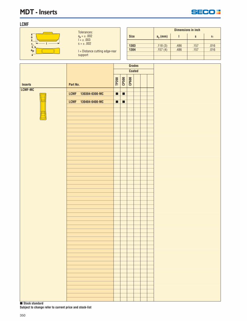
350
LCMF
[ Stock standardSubject to change refer to current price and stock-list
Size
Dimensions in inch
ap (mm) l s rε
1303 .118 (3) .486 .157 .0161304 .157 (4) .486 .157 .016
Inserts Part No.
Grades
Coated
TP20
0
CP50
0
CP60
0
LCMF-MCLCMF 130304-0300-MC [ [
LCMF 130404-0400-MC [ [
Tolerances:ap = ± .002l = ± .003s = ± .002
l = Distance cutting edge-rear support

MDT - Inserts
351
LCGA
[ Stock standard *Note! Toolholders have to be modifiedSubject to change refer to current price and stock-list
Size
Dimensions in inch
ap l s rε ar
-0115 .045 .486 .157 – .055-0135 .053 .486 .157 – .063-0165 .065 .486 .157 .004 .075-0190 .075 .486 .157 .004 .085-0215 .085 .486 .157 .006 .094-0265 .104 .486 .157 .008 .114-0300 .118 .486 .157 .008 –-0400 .157 .486 .157 .008 –
Inserts Standard For lock-ring Part No. Note
Grades
Coated
CP50
0
LCGA-FGDIN 471DIN 472
SMS 1581SMS 1582
1,0 mm LCGA 130300-0115-FG * [1,2 mm 130300-0135-FG * [1,5 mm 130301-0165-FG * [
1,75 mm 130301-0190-FG * [2,0 mm 130301-0215-FG * [2,5 mm 130302-0265-FG [
– 130302-0300-FG [
– LCGA 130402-0400-FG [

MDT - Inserts
352
LCMF and LCMR
[ Stock standardSubject to change refer to current price and stock-list
Size
Dimensions in inch
ap (mm) l s rε
mm-version1603 .118 (3) .630 .177 .008-.0161604 .157 (4) .630 .177 .008-.0311605 .197 (5) .630 .177 .016-.0311606 .236 (6) .630 .177 .016-.0393008-08 .315 (8) 1.150 .219 .016-.0473008-10 .393 (10) 1.150 .219 .031-.047inch-version1603 .125 .630 .177 .0081605 .187 .630 .177 .0201606 .250 .630 .177 .020
Inserts Part No.
Grades
Coated Uncoated
TP20
0
CP20
0
CP50
0
TK15
0
883
890
LCMF-FTLCMF 160302-0300-FT [ [ [
160304-0300-FT [ [ [
LCMF 160402-0400-FT [ 160404-0400-FT [ [ [ 160408-0400-FT [ [
LCMF 160504-0500-FT [ [ [ 160508-0500-FT [ [
LCMF 160604-0600-FT [ [ 160608-0600-FT [ [ [ [ 160610-0600-FT [ [
LCMF 300804-0800-FT [ [ [ 300808-0800-FT [ [ [ 300808-1000-FT [ 300812-0800-FT [ [ 300812-1000-FT [
inch-versionLCMF 160302-A125-FT [
160505-A187-FT [ [ 160605-A250-FT [ [ [
LCMF-MTLCMF 160302-0300-MT [ [
160304-0300-MT [ [ [
LCMF 160404-0400-MT [ [ [ 160408-0400-MT [ [ [
LCMF 160504-0500-MT [ [ [ 160508-0500-MT [ [
LCMF 160604-0600-MT [ [ 160608-0600-MT [ [ [ 160610-0600-MT [ [
inch-versionLCMF 160302-A125-MT [
160505-A187-MT [ 160605-A250-MT [ [
Tolerances:ap = ± .002l = ± .003s = ± .0015
l = Distance cutting edge-rear support

MDT - Inserts
353
LCMF and LCMR
[ Stock standardSubject to change refer to current price and stock-list
Inserts Part No.
Grades
Coated Uncoated
TP20
0
CP20
0
CP50
0
TK15
0
883
890
LCMF-MGLCMF 160304-0300-MG [ [
LCMF 160404-0400-MG [ [
LCMF 160504-0500-MG [ [
LCMF 160608-0600-MG [ [
LCMR-FTLCMR 160304-0300-FT [ [ [
LCMR 160402-0400-FT [ [ 160404-0400-FT [ [ [
LCMR 160504-0500-FT [ [ [
LCMR 160608-0600-FT [ [ [
LCMR 300808-0800-FT [ [ [ 300808-1000-FT [ 300812-0800-FT [ [ 300812-1000-FT [
LCMR-MTLCMR 160304-0300-MT [ [ [
LCMR 160404-0400-MT [ [ 160408-0400-MT [
LCMR 160504-0500-MT [ [ 160508-0500-MT [
LCMR 160608-0600-MT [ [ [ 160610-0600-MT [

MDT - Inserts
354
LCMF and LCMR
[ Stock standardSubject to change refer to current price and stock-list
Size
Dimensions in inch
ap (mm) l s rε
mm-version1603M0 .118 (3) .674 .177 .0591604M0 .157 (4) .679 .177 .0791605M0 .197 (5) .699 .177 .0981606M0 .236 (6) .714 .177 .1183008M0-08 .315 (8) 1.183 .216 .1573008M0-10 .393 (10) 1.183 .216 .197inch-version160300 .125 .683 .177 .063160500 .187 .722 .177 .094160600 .250 .719 .177 .125
Inserts Part No.
Grades
Coated Uncoated
TP20
0
CP20
0
CP50
0
TK15
0
883
890
LCMF-MPLCMF 1603M0-0300-MP [ [ [
1604M0-0400-MP [ [ [ 1605M0-0500-MP [ [ [ 1606M0-0600-MP [ [ [ [ 3008M0-0800-MP [ [ [ 3008M0-1000-MP [ [
inch-version 160300-A125-MP [ [ [ 160500-A187-MP [ [ 160600-A250-MP [ [ [
LCMR-MPLCMR 1603M0-0300-MP [ [ [ [
1604M0-0400-MP [ [ [ [ 1605M0-0500-MP [ [ [ [ 1606M0-0600-MP [ [ [ [ 3008M0-0800-MP [ [ [ 3008M0-1000-MP [ [
Tolerances:ap = ± .002l = ± .003s = ± .0015
l = Distance cutting edge-rear support

MDT - Inserts
355
LCMF and LCMR
[ Stock standardSubject to change refer to current price and stock-list
Size
Dimensions in inch
ap (mm) l s rε
1603 .118 (3) .630 .177 .008-.0161604 .157 (4) .630 .177 .008-.0161605 .197 (5) .630 .177 .0161606 .236 (6) .630 .177 .016-.032
Inserts Part No. Lead Angle (κ)
Grades
Coated
TP20
0
CP50
0
CP60
0
LCMF-MCLCMF 160302-0300-MC – [
160304-0300-MC – [ [ [ 160302-0300-MCR6 6 [ 160302-0300-MCL6 6 [ 160302-0300-MCR15 15 [ 160302-0300-MCL15 15 [
LCMF 160402-0400-MC – [ 160402-0400-MCR6 6 [ 160402-0400-MCL6 6 [ 160402-0400-MCR15 15 [ 160402-0400-MCL15 15 [ 160404-0400-MC – [ [ [
LCMF 160504-0500-MC – [ [ [
LCMF 160604-0600-MC – [ [ [ 160608-0600-MC – [ [
LCMR-MCLCMR 160302-0300-MC – [
160404-0400-MC – [ 160504-0500-MC – [ 160604-0600-MC – [
Tolerances:ap = ± .002l = ± .003s = ± .0015
l = Distance cutting edge-rear support

MDT - Inserts
356
LCG.-FG - Radial grooves
[ Stock standard *Note! Toolholders have to be modifiedSubject to change refer to current price and stock-list
Size
Dimensions in inch
ap l s rε ar
0115 .045 .630 .177 – .0450135 .053 .630 .177 – .0530165 .065 .630 .177 .004 .0650190 .075 .630 .177 .004 .0750215 .085 .630 .177 .006 .0850265 .104 .630 .177 .008 –0300 .118 .630 .177 .008 –0320 .126 .630 .177 .008 –0340 .134 .630 .177 .008 –0400 .157 .630 .177 .008 –0420 .165 .630 .177 .008 –0440 .173 .630 .177 .008 –0500 .197 .674 .177 .008 –0520 .205 .674 .177 .008 –0600 .236 .693 .177 .008 –0635 .250 .693 .177 .008 –A031 .031 .630 .177 .004 .050A063 .063 .630 .177 .008 .125A094 .094 .630 .177 .008 .180
Inserts Standard For lock-ring Part No. Note
Grades
Coated
CP50
0
LCGN-FGDIN 471DIN 472
SMS 1581SMS 1582
1.0 mm LCGN 160300-0115-FG * [1.2 mm 160300-0135-FG * [1.5 mm 160301-0165-FG * [1.75 mm 160301-0190-FG * [2.0 mm 160301-0215-FG * [2.5 mm 160302-0265-FG [
– 160302-0300-FG [3.0 mm 160302-0320-FG [
– 160302-0340-FG [– 160402-0400-FG [
4.0 mm 160402-0420-FG [– 160402-0440-FG [– 160502-0500-FG [
5.0 mm 160502-0520-FG [– 160602-0600-FG [– 160602-0635-FG [
LCGF-FG– LCGF 160301-0300-FG [
LCGN-FG
Right handshown
– LCGN 160301-A031RH-FG * [– 160301-A031LH-FG * [– 160302-A063RH-FG * [– 160302-A063LH-FG * [– 160302-A094RH-FG * [– 160302-A094LH-FG * [

MDT - Inserts
357
LCGN - O-ring
[ Stock standardSubject to change refer to current price and stock-list
Size
Dimensions in inch
ap l s t rε r ar
0240-DY .130 .654 .177 .090 .009 .010 .0790300-DY .161 .654 .177 .090 .039 .010 .0980180-DY .094 .654 .177 .070 .019 .010 .0610265-DY .142 .654 .177 .090 .016 .012 .0900160-ST .094 .654 .177 .070 .020 .010 .0470240-ST .126 .654 .177 .070 .020 .010 .0750300-ST .150 .654 .177 .090 .039 .012 .0940355-ST .189 .673 .177 .112 .029 .012 .110
Inserts StandardFor O-ring
mmFor O-ring
inch Part No.
Grades
Coated
CP50
0
LCGN-DY
O-ring, dynamic
SMS 1588BS 4518
2.4 .094 LCGN 160405-0240-DY [3.0 .118 160410-0300-DY [
ISO 3601DIN 3771BS 1806
1.8 .070 LCGN 160305-0180-DY [2.6 .103 160405-0265-DY [
LCGN-ST
O-ring, static
SMS 1588BS 4518
1.6 .063 LCGN 160305-0160-ST [2.4 .094 160305-0240-ST [3.0 .118 160410-0300-ST [
ISO 3601DIN 3771BS 1806
3.5 .139 LCGN 160507-0355-ST [

MDT - Inserts
358
LCGN - Full radius grooving
*Note! Toolholders have to be modified.
LCGN - DIN 76
[ Stock standard *Note! Toolholders have to be modifiedSubject to change refer to current price and stock-list
Size
Dimensions in inch
l s rε ar
0100 .654 .177 .039 .0940120 .654 .177 .047 .0940150 .654 .177 .059 -0200 .654 .177 .079 -0300 .693 .177 .118 -
Inserts For radius inch (mm) Part No.
Grades
Coated
CP50
0
LCGN-R.039 (1.0 mm) LCGN 1603M0-0100R-R* [.039 (1.0mm) 1603M0-0100L-R* [.047 (1.2 mm) 1603M0-0120R-R* [.047 (1.2mm) 1603M0-0120L-R* [.059 (1.5 mm) 1603M0-0150-R [.079 (2.0 mm) 1604M0-0200-R [
Size
Dimensions in inch
t l s rε
0100 .086 .654 .177 .0240150 .126 .673 .177 .0300200 .181 .693 .177 .039
Inserts For Max T.P.I. (mm) Part No.
Grades
Coated
CP50
0
LCGN-D7624 (1.0 ) LCGN 160306-0100R-D76* [16 (1.5) 160507-0150R-D76 [
Right-hand version shown
Right-hand version shown

MDT - Inserts
359
LCGN - Partial profile 55°
*Note! Toolholders have to be modified.
LCGN - Partial profile 60°
[ Stock standard *Note! Toolholders have to be modifiedSubject to change refer to current price and stock-list
Size
Dimensions in inch
l s rε
1603-A .654 .177 .0031603-G .654 .177 .007
Inserts TPI Pitch mm Part No.
Grades
Coated
CP50
0
LCGN...-.5548-16 0,5-1,5 LCGN 1603-A55* [14-8 1,75-3,0 LCGN 1603-G55* [
Size
Dimensions in inch
l s rε
1603-A .654 .177 .0031603-G .654 .177 .007
Inserts TPI Pitch mm Part No.
Grades
Coated
CP50
0
LCGN...-.6048-16 0,5-1,5 LCGN 1603-A60* [14-8 1,75-3,0 LCGN 1603-G60* [
Tolerances:l = ± .001re = ± .001
Tolerances:l = ± .001 re = ± .001

MDT, Secomax - PCBN, Inserts
360
LCGN
LCGN
[ Stock standardSubject to change refer to current price and stock-list
Size
Dimensions in inch
ap l s rε
1303 .118 (3) .485 .157 .0161304 .157 (4) .485 .157 .016
Inserts Part No.
Grades
CBN1
0
CBN2
00
LCGN-LF
E = HonedS = Chamfered and honedLF = Complete top layer
Tip sizes:See page 62
LCGN 130304-0300E-LF [ 130304-0300S-LF [ [
LCGN 130404-0400E-LF [ 130404-0400S-LF [ [
Size
Dimensions in inch
ap (mm) l s rε
1303 .118 (3) .485 .157 .0591304 .157 (4) .485 .157 .079
Inserts Part No.
Grades
CBN1
0
CBN
200
LCGN...M0-LF
E = HonedS = Chamfered and honedLF = Complete top layer
Tip sizes:See page 62
LCGN 1303M0-0300E-LF [ 1303M0-0300S-LF [ [ 1304M0-0400S-LF [ [
Tolerances:ap = ±.001l = ±.0015s = ±.002
Tolerances:ap = ±.001l = ±.0015s = ±.002rε = ±.001

MDT, Secomax - PCBN, Inserts
361
LCGN
LCGN
[ Stock standardSubject to change refer to current price and stock-list
Size
Dimensions in inch
ap (mm) l s rε
1603 .118 (3) .626 .177 .0161604 .157 (4) .626 .177 .0161605 .197 (5) .626 .177 .0161606 .236 (6) .626 .177 .016
Inserts Part No.
Grades
CBN1
0
CBN2
00
LCGN
E = HonedS = Chamfered and honedLF = Complete top layer
Tip sizes:See page 62
LCGN 160304-0300E-LF [ 160304-0300S-LF [ [
LCGN 160404-0400E-LF [ 160404-0400S-LF [ [
LCGN 160504-0500E-LF [ 160504-0500S-LF [ [
LCGN 160604-0600E-LF [ 160604-0600S-LF [ [
Size
Dimensions in inch
ap l s rε
1603 .118 .654 .173 .0591604 .157 .654 .171 .0791605 .197 .677 .169 .0981606 .236 .677 .165 .118
Inserts Part No.
Grades
CBN1
0
CBN
200
LCGN...M0-LF
E = HonedS = Chamfered and honedLF = Complete top layer
Tip sizes:See page 62
LCGN 1603M0-0300E-LF [ 1603M0-0300E25-LF [ 1603M0-0300S-LF [ [
LCGN 1604M0-0400E25-LF [ 1604M0-0400S-LF [ [
LCGN 1605M0-0500E25-LF [ 1605M0-0500S-LF [ [
LCGN 1606M0-0600E25-LF [ 1606M0-0600S-LF [ [
Tolerances:ap = ±.001l = ±.0015s = ±.002
Tolerances:ap = ±.001l = ±.0015s = ±.002rε = ±.001


![Transf Seco[EATON]](https://static.fdocuments.in/doc/165x107/55cf9d87550346d033ae032c/transf-secoeaton.jpg)


