Technical Information Manual - Polyflor · · 2013-04-09Welding vinyl flooring P 13. Adhesives...
49
Technical Information Manual
-
Upload
hoangtuyen -
Category
Documents
-
view
218 -
download
2
Transcript of Technical Information Manual - Polyflor · · 2013-04-09Welding vinyl flooring P 13. Adhesives...
Technical Information Manual
At Polyflor, we realise that the performance of our products is dependent upon
many factors and that the floorcovering itself is only one of those factors. Correct
subfloor preparation and dryness, the workmanship of the installer, how the product
is maintained and the selection of the correct floorcovering are all equally
important. Our objective is to support the customer, whether it is the architect, the
specifier, the contractor or the end user, by providing all the relevant information
necessary to ensure that the maximum benefit is gained from our products in use.
This manual forms part of that support, together with technically trained Sales
Representatives, a knowledgeable Customer Technical Services team and an
installation training school.
If you have any queries regarding product selection, specification, installation,
performance or maintenance of any Polyflor products, then do not hesitate to
contact us. Our aim is to resolve problems prior to the installation of our products
rather than have problems to resolve after they are installed.
At the date of issue, the data presented is correct.
However, Polyflor reserve the right to make changes which do not adversely affect performance or quality.
1. Introduction
2. Preparation of subfloors
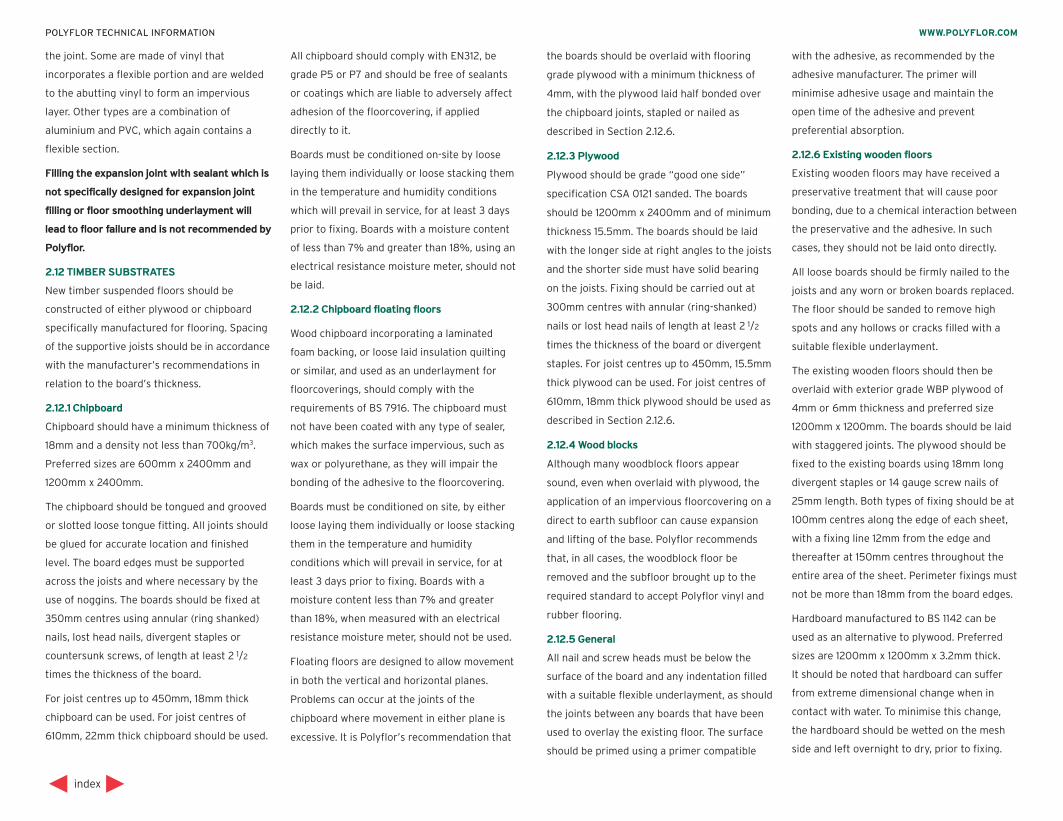
3. Installation of Homogeneous and Safety vinyl sheet
4. Installation of Homogeneous vinyl tiles
5. Installation of Heterogeneous vinyl sheet
6. Installation of Rubber sheet
7. Installation of Rubber tiles
8. Electro Static Dissipative (ESD) floorcoverings
9. Installation of vinyl Wallcoverings
10. Installation of Accessories
11. Inlaid designs and borders
12. Welding vinyl flooring
13. Adhesives
14. Tools and Equipment
15. Recommended finishes
16. Resistance to chemicals
17. Use area classifications
18. Operating service temperatures
19. Maintenance
WWW.POLYFLOR.COMPOLYFLOR TECHNICAL INFORMATION
IndexTechnical Support
Polyflor Customer Technical Services
Tel: +44 (0)161 767 1912
Web: www. polyflor.com
Email: [email protected]

1
index
WWW.POLYFLOR.COMPOLYFLOR TECHNICAL INFORMATION
Introductionperformance must be sustainable for the
anticipated life of the product, allowing for
foreseeable actions such as general wear and
tear and regular maintenance. This is
extremely important for the Essential
Requirements as defined by the European
Union for all construction products.
Consideration at the initial specification stage
must be given to the occupational usage of the
building and the building type. Particular
attention must be paid to the type and density
of traffic (both pedestrian and wheeled), any
special acoustical, electrical resistance or slip
resistance requirements, as well as reaction to
chemicals and staining agents, and physical
properties such as resistance to point and
rolling loads.
Should you wish to clarify any points regarding
Polyflor contract flooring or accessories, then
please contact Polyflor or our appointed
agents. Our Technical Sales Team and
Customer Technical Services Department can
provide advice on the suitability, performance
and application of any of the Polyflor products.
1.1.1 Project pre-planning
One important consideration at the outset is
the maintenance aspects of the floorcovering
to be installed. Floorcoverings with enhanced
slip characteristics have a higher surface
coefficient of friction and requires different
maintenance than a traditional smooth
floorcovering. Colour also plays a very
important part and one should remember that
light colours will show soiling more easily and
could require a more intensive maintenance
programme than darker colours.
Having decided upon your floorcovering, it is
essential that the product, together with its
accessories, are installed correctly within
pre-defined time and budget constraints.
To achieve this, the tender documentation
should include the maximum amount of
information possible, such as:
1. Full details of the subfloor construction,
especially on solid subfloors and any treatments
or additives. Include the expected dates for
completion of each stage.
2. Full details of standard features such as
welding, site formed coving or pre-formed coving.
In addition, it should include other features such
as pattern or border detail and requirements
such as door trims, diminishing strips etc.
3. Reference to any tests which must be carried
out e.g. for moisture, electrical resistance, screed
strength and flatness/level.
4. Drawings showing the direction of decoration
or where sheet must be laid in a particular
direction.
5. A statement of the standard of workmanship
required, clearly indicating items which will
be unacceptable at the handover inspection.
6. Full details of finishing requirements.
These may include; removal and safe disposal of
waste, retention of flooring over a certain size, a
construction clean, initial polish where applicable
and protection of the finished floor prior to
customer handover.
By including this level of detail in the tender
document, the flooring contractor is able to
give an accurate costing and advise on the
length of time required to complete the work at
that cost. Once the tender is accepted, ideally
discussions should be held to highlight any
potential problems well in advance and to
ascertain the services required on site when
the floorcovering is installed.
British Standard Code of Practice BS 8203
provides detailed recommendations for the
installation of sheet and tile flooring on both
new and existing floor constructions and is
endorsed by Polyflor for the installation of
Polyflor vinyl and rubber flooring.
This technical information manual is intended
as a guide to all parties involved in the
specification, installation and maintenance of
Polyflor vinyl floorcovering. It will not replace
the skills of a trained floor layer and Polyflor
always recommends the use of reputable
flooring contractors, whose experience will
prove invaluable at all stages of a project.
Selecting a flooring contractor solely on price
can lead to a poor installation and a dissatisfied
end user.
A successful installation not only depends on
the skills of the floor layer but also on the
planning of the project prior to installation.
Consultation between all parties concerned will
eliminate problems and will ensure a successful
installation, which meets the design
requirements within the allotted time scale.
1.1 PRODUCT SELECTION
Selection of the correct floorcovering is of
paramount importance. Not only must the
floorcovering meet the designer’s initial
performance specification but the product
2
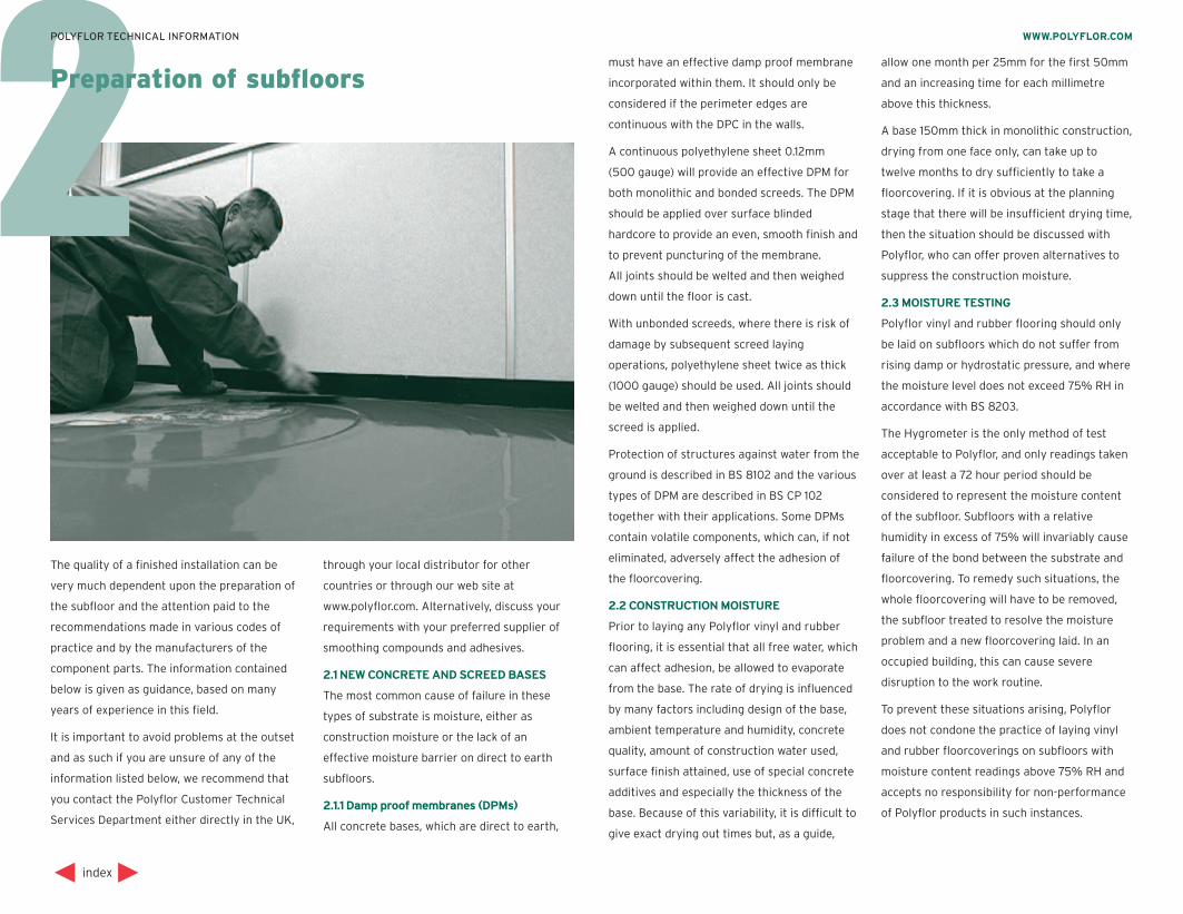
The quality of a finished installation can be
very much dependent upon the preparation of
the subfloor and the attention paid to the
recommendations made in various codes of
practice and by the manufacturers of the
component parts. The information contained
below is given as guidance, based on many
years of experience in this field.
It is important to avoid problems at the outset
and as such if you are unsure of any of the
information listed below, we recommend that
you contact the Polyflor Customer Technical
Services Department either directly in the UK,
through your local distributor for other
countries or through our web site at
www.polyflor.com. Alternatively, discuss your
requirements with your preferred supplier of
smoothing compounds and adhesives.
2.1 NEW CONCRETE AND SCREED BASES
The most common cause of failure in these
types of substrate is moisture, either as
construction moisture or the lack of an
effective moisture barrier on direct to earth
subfloors.
2.1.1 Damp proof membranes (DPMs)
All concrete bases, which are direct to earth,
must have an effective damp proof membrane
incorporated within them. It should only be
considered if the perimeter edges are
continuous with the DPC in the walls.
A continuous polyethylene sheet 0.12mm
(500 gauge) will provide an effective DPM for
both monolithic and bonded screeds. The DPM
should be applied over surface blinded
hardcore to provide an even, smooth finish and
to prevent puncturing of the membrane.
All joints should be welted and then weighed
down until the floor is cast.
With unbonded screeds, where there is risk of
damage by subsequent screed laying
operations, polyethylene sheet twice as thick
(1000 gauge) should be used. All joints should
be welted and then weighed down until the
screed is applied.
Protection of structures against water from the
ground is described in BS 8102 and the various
types of DPM are described in BS CP 102
together with their applications. Some DPMs
contain volatile components, which can, if not
eliminated, adversely affect the adhesion of
the floorcovering.
2.2 CONSTRUCTION MOISTURE
Prior to laying any Polyflor vinyl and rubber
flooring, it is essential that all free water, which
can affect adhesion, be allowed to evaporate
from the base. The rate of drying is influenced
by many factors including design of the base,
ambient temperature and humidity, concrete
quality, amount of construction water used,
surface finish attained, use of special concrete
additives and especially the thickness of the
base. Because of this variability, it is difficult to
give exact drying out times but, as a guide,
allow one month per 25mm for the first 50mm
and an increasing time for each millimetre
above this thickness.
A base 150mm thick in monolithic construction,
drying from one face only, can take up to
twelve months to dry sufficiently to take a
floorcovering. If it is obvious at the planning
stage that there will be insufficient drying time,
then the situation should be discussed with
Polyflor, who can offer proven alternatives to
suppress the construction moisture.
2.3 MOISTURE TESTING
Polyflor vinyl and rubber flooring should only
be laid on subfloors which do not suffer from
rising damp or hydrostatic pressure, and where
the moisture level does not exceed 75% RH in
accordance with BS 8203.
The Hygrometer is the only method of test
acceptable to Polyflor, and only readings taken
over at least a 72 hour period should be
considered to represent the moisture content
of the subfloor. Subfloors with a relative
humidity in excess of 75% will invariably cause
failure of the bond between the substrate and
floorcovering. To remedy such situations, the
whole floorcovering will have to be removed,
the subfloor treated to resolve the moisture
problem and a new floorcovering laid. In an
occupied building, this can cause severe
disruption to the work routine.
To prevent these situations arising, Polyflor
does not condone the practice of laying vinyl
and rubber floorcoverings on subfloors with
moisture content readings above 75% RH and
accepts no responsibility for non-performance
of Polyflor products in such instances.
index
WWW.POLYFLOR.COMPOLYFLOR TECHNICAL INFORMATION
Preparation of subfloors
In countries outside of the UK, alternative
moisture measurement methods are also used.
The guidelines for the maximum acceptable
vapour emission rate of concrete using
anhydrous calcium chloride is 3lbs per 1000
square feet per 24 hour period for all the
Polyflor and Polysafe floorcoverings.
2.4 EXISTING CONCRETE AND SCREED BASES
Existing concrete and sand/cement screed
bases as described in BS 8204, if laid directly
to ground, must contain an effective DPM. If
one is not present or is suspect, a suitable
surface DPM should be applied.
In most instances, a cementicious smoothing
compound of at least 3mm thickness must be
applied prior to the installation of the vinyl
floorcovering. The smoothing underlayment
supplier will provide details on which product
within their range must be used to suit the end
use application and subfloor construction,
together with details of which primer should
be used.
2.5 POWER FLOATED CONCRETE
Power floated concrete bases as described in
BS 8204, if laid directly to ground, must
contain an effective DPM. If one is not present
or is suspect, a suitable surface DPM should be
applied. Smooth dense concrete subfloors –
such as those created by a power floated finish
– can prove difficult to bond to, due to the
impervious nature of the surface. In such
instances, the floor should initially be ground
or shot blasted to remove the top surface and
then made good.
In most instances, a cementicious smoothing
compound of at least 3mm thickness must be
applied prior to the installation of the vinyl
floorcovering. The smoothing underlayment
supplier will provide details on which product
within their range must be used to suit the end
use application and subfloor construction,
together with details of which primer should
be used.
Surface hardeners or curing agents should not
be used with power floated concrete, as these
can also impair the adhesion of the
floorcovering.
2.6 MASTIC ASPHALT UNDERLAY
Mastic asphalt underlays as described in
BS 8204: Part 5 should conform to BS 6925.
Comprising asphaltic cement and suitable
aggregates, the asphalt is applied in its hot
state onto a glass fibre quilt. Normally a
thickness of 15mm to 20mm is applied and the
asphalt brought to a finish with a wooden float.
The resulting underlay is impervious to
moisture and, if continuous with the DPC in the
walls, makes an excellent subfloor for Polyflor
vinyl and rubber flooring, providing a 3mm
thick surface underlayment is first applied.
The asphalt must not just be skim coated it is
important to ensure that the smoothing
underlayment is of a type recommended for
use on asphalt floors and that a suitable primer
key coat is applied if so directed.
Never apply Polyflor floorcoverings direct to a
mastic asphalt subfloor.
2.7 MAGNESITE / GRANWOOD FLOORS
Composition floors which are composed of
magnesium oxychloride cement or polyvinyl
acetate/cement are highly absorbent. As such,
if overlaid with an impervious material, they
can break down due to the effects of rising
moisture, as the majority of these floors do not
incorporate an effective DPM. In all instances
where the material is laid directly to ground,
Polyflor recommend that the screed be uplifted
and relaid incorporating an effective DPM.
For floors that are on the first floor or above,
cracks and small hollows should be patch filled
and a cementicious smoothing compound of at
least 3mm thickness must then be applied, prior
to the installation of the vinyl floorcovering.
The smoothing underlayment supplier will
provide details on which product within their
range must be used to suit the end use
application and subfloor construction, together
with details of which primer should be used.
2.8 TERRAZZO
Terrazzo has a dense hard surface, which is
normally impervious. The floor must be sound
and firmly fixed and any loose or powdery
material removed from the joints. The surface
should be thoroughly washed/degreased to
remove any surface contaminants and any
cracks cleaned out and filled with a suitable
resin bonded cement/sand mixture. The surface
may also need some mechanical abrasion to
enable the smoothing underlayment to key to
the surface.
In most instances, a cementicious smoothing
compound of at least 3mm thickness must then
be applied prior to the installation of the vinyl
floorcovering. The smoothing underlayment
supplier will provide details on which product
within their range must be used to suit the end
use application and subfloor construction,
together with details of which primer should
be used.
2.9 QUARRY TILES/CERAMIC TILES
Heavily glazed surfaces are quite common with
these types of flooring and tiles must be sound
and firmly fixed with all loose and powdery
grout removed from the joints. Generally the
tiles will require mechanical abrasion of the
surface in order to provide a key for the
application of a smoothing underlayment.
The surface should be thoroughly washed /
degreased to remove any surface contaminants
and then a cementicious smoothing compound
of at least 3mm thickness must then be applied
prior to the installation of the vinyl
floorcovering. The smoothing underlayment
supplier will provide details on which product
within their range must be used to suit the end
use application and subfloor construction,
together with details of which primer should
be used.
2.10 SYNTHETIC ANHYDRITE SCREEDS
This type of screed can be affected by laitance
and moisture in the smoothing compound,
resulting in the loss of bond. As such, it may
need mechanical removal and the application of
a special primer. We would always recommend
that you discuss this application with your
adhesive and underlayment manufacturers.
If a failure occurs, it is normally below the vinyl
floorcovering and as such Polyflor will not
accept responsibility for failure.
2.11 EXPANSION JOINTS
Expansion joints are incorporated into build-
ings to permit movement without cracking. It is
important that these joints extend through the
floorcovering.
Never lay Polyflor vinyl and rubber flooring
over expansion joints.
Proprietary expansion joint covers are available
which blend with the floorcovering and disguise
index
WWW.POLYFLOR.COMPOLYFLOR TECHNICAL INFORMATION
the joint. Some are made of vinyl that
incorporates a flexible portion and are welded
to the abutting vinyl to form an impervious
layer. Other types are a combination of
aluminium and PVC, which again contains a
flexible section.
Filling the expansion joint with sealant which is
not specifically designed for expansion joint
filling or floor smoothing underlayment will
lead to floor failure and is not recommended by
Polyflor.
2.12 TIMBER SUBSTRATES
New timber suspended floors should be
constructed of either plywood or chipboard
specifically manufactured for flooring. Spacing
of the supportive joists should be in accordance
with the manufacturer’s recommendations in
relation to the board’s thickness.
2.12.1 Chipboard
Chipboard should have a minimum thickness of
18mm and a density not less than 700kg/m3.
Preferred sizes are 600mm x 2400mm and
1200mm x 2400mm.
The chipboard should be tongued and grooved
or slotted loose tongue fitting. All joints should
be glued for accurate location and finished
level. The board edges must be supported
across the joists and where necessary by the
use of noggins. The boards should be fixed at
350mm centres using annular (ring shanked)
nails, lost head nails, divergent staples or
countersunk screws, of length at least 2 1/2
times the thickness of the board.
For joist centres up to 450mm, 18mm thick
chipboard can be used. For joist centres of
610mm, 22mm thick chipboard should be used.
All chipboard should comply with EN312, be
grade P5 or P7 and should be free of sealants
or coatings which are liable to adversely affect
adhesion of the floorcovering, if applied
directly to it.
Boards must be conditioned on-site by loose
laying them individually or loose stacking them
in the temperature and humidity conditions
which will prevail in service, for at least 3 days
prior to fixing. Boards with a moisture content
of less than 7% and greater than 18%, using an
electrical resistance moisture meter, should not
be laid.
2.12.2 Chipboard floating floors
Wood chipboard incorporating a laminated
foam backing, or loose laid insulation quilting
or similar, and used as an underlayment for
floorcoverings, should comply with the
requirements of BS 7916. The chipboard must
not have been coated with any type of sealer,
which makes the surface impervious, such as
wax or polyurethane, as they will impair the
bonding of the adhesive to the floorcovering.
Boards must be conditioned on site, by either
loose laying them individually or loose stacking
them in the temperature and humidity
conditions which will prevail in service, for at
least 3 days prior to fixing. Boards with a
moisture content less than 7% and greater
than 18%, when measured with an electrical
resistance moisture meter, should not be used.
Floating floors are designed to allow movement
in both the vertical and horizontal planes.
Problems can occur at the joints of the
chipboard where movement in either plane is
excessive. It is Polyflor’s recommendation that
the boards should be overlaid with flooring
grade plywood with a minimum thickness of
4mm, with the plywood laid half bonded over
the chipboard joints, stapled or nailed as
described in Section 2.12.6.
2.12.3 Plywood
Plywood should be grade “good one side”
specification CSA 0121 sanded. The boards
should be 1200mm x 2400mm and of minimum
thickness 15.5mm. The boards should be laid
with the longer side at right angles to the joists
and the shorter side must have solid bearing
on the joists. Fixing should be carried out at
300mm centres with annular (ring-shanked)
nails or lost head nails of length at least 2 1/2
times the thickness of the board or divergent
staples. For joist centres up to 450mm, 15.5mm
thick plywood can be used. For joist centres of
610mm, 18mm thick plywood should be used as
described in Section 2.12.6.
2.12.4 Wood blocks
Although many woodblock floors appear
sound, even when overlaid with plywood, the
application of an impervious floorcovering on a
direct to earth subfloor can cause expansion
and lifting of the base. Polyflor recommends
that, in all cases, the woodblock floor be
removed and the subfloor brought up to the
required standard to accept Polyflor vinyl and
rubber flooring.
2.12.5 General
All nail and screw heads must be below the
surface of the board and any indentation filled
with a suitable flexible underlayment, as should
the joints between any boards that have been
used to overlay the existing floor. The surface
should be primed using a primer compatible
with the adhesive, as recommended by the
adhesive manufacturer. The primer will
minimise adhesive usage and maintain the
open time of the adhesive and prevent
preferential absorption.
2.12.6 Existing wooden floors
Existing wooden floors may have received a
preservative treatment that will cause poor
bonding, due to a chemical interaction between
the preservative and the adhesive. In such
cases, they should not be laid onto directly.
All loose boards should be firmly nailed to the
joists and any worn or broken boards replaced.
The floor should be sanded to remove high
spots and any hollows or cracks filled with a
suitable flexible underlayment.
The existing wooden floors should then be
overlaid with exterior grade WBP plywood of
4mm or 6mm thickness and preferred size
1200mm x 1200mm. The boards should be laid
with staggered joints. The plywood should be
fixed to the existing boards using 18mm long
divergent staples or 14 gauge screw nails of
25mm length. Both types of fixing should be at
100mm centres along the edge of each sheet,
with a fixing line 12mm from the edge and
thereafter at 150mm centres throughout the
entire area of the sheet. Perimeter fixings must
not be more than 18mm from the board edges.
Hardboard manufactured to BS 1142 can be
used as an alternative to plywood. Preferred
sizes are 1200mm x 1200mm x 3.2mm thick.
It should be noted that hardboard can suffer
from extreme dimensional change when in
contact with water. To minimise this change,
the hardboard should be wetted on the mesh
side and left overnight to dry, prior to fixing.
index
WWW.POLYFLOR.COMPOLYFLOR TECHNICAL INFORMATION

Failure to wet the hardboard can result in
buckling due to moisture absorption from the
water-based adhesive.
Plywood and hardboard should be treated as
described in Section 2.12.3 prior to application
of the floorcovering.
With suspended timber at ground level, it is of
vital importance to obtain good ventilation
below the floor through the existence of
airbricks. Without good ventilation, the
application of an impervious floorcovering
could lead to dry rot in the structure beneath.
Most smoothing compounds are unsuitable for
applying to timber bases due to the movement
of the base. Seek advice from the smoothing
underlayment manufacturer for the correct
grade of product for your specific application.
Cementicious smoothing compounds should
only be used to patch fill hollows on timber
substrates. Once level, they should be overlaid
with flooring grade plywood, as described
previously.
2.13 OTHER SUBSTRATES
2.13.1 Metal bases
Metal bases are generally, but not exclusively,
steel and can be contaminated with rust or
oxidisation, oil and grease. The surface should
be thoroughly degreased and then abraded or
wire brushed to remove the rust or oxidisation.
Any high spots may need to be ground off.
In most instances, but not where there is
excessive vertical or lateral flexing or
movement, a cementicious smoothing
compound of at least 3mm thickness must then
be applied prior to the installation of the vinyl
floorcovering. The smoothing underlayment
supplier will provide details on which product
within their range must be used to suit the end
use application and subfloor construction,
together with details of which primer should
be used.
2.13.2 Painted or epoxy coated floors
Epoxy and polyurethane surface coatings
should be removed, in order to ensure that no
breakdown of the sub-floor occurs after
installation of the resilient floorcovering.
Painted floors will impair the adhesion of the
resilient floorcovering and should be removed
prior to the application of the floorcovering.
Mechanical methods such as grinding or
blasting are the most suitable methods for
removing these coatings. However, where the
paint proves difficult to remove, the floor may
need to be scabbled. If the epoxy coating is
well bonded to the subfloor, it is possible to
apply the floorcovering after grinding or
blasting. In both instances, the surface should
then be made good with a 3mm minimum
coating of a suitable cementicious smoothing
underlayment applied in accordance with the
manufacturer’s recommendations, which may
include the application of a primer key coat.
2.13.3 Loose lay isolating membranes
Polyflor recommend that subfloors be prepared
in accordance with the relevant code of practice
BS 8203. Any installations incorporating loose
lay isolating membrane systems within the
marketplace, which are used to overlay
contaminated subfloors, existing floor
coverings, etc. are solely underwritten by the
individual membrane manufacturer.
2.13.4 Existing floorcoverings
Polyflor vinyl and rubber flooring should never
be laid over existing floorcoverings and in such
instances where this is carried out, Polyflor
accepts no responsibility for non-performance
of its products.
All existing floorcoverings must be uplifted and
as much as possible of the old adhesive
removed from the subfloor. Special care must
be taken on very old floors, as some products –
but not Polyflor – contained asbestos. In these
instances, contact Polyflor for further
information.
The removed floorcoverings should be
reclaimed and recycled, providing that there is
no heavy contamination. Polyflor is one of two
founder members of Recofloor, the industry
funded vinyl take-back scheme. To enquire
about this scheme and recycling end of life
vinyl flooring (uplifted and off-cuts), email
Recofloor at [email protected].
A suitable 3mm thick floor smoothing
underlayment should then be applied to the
whole floor. Failure to remove sufficient
adhesive can lead to premature failure of the
underlayment.
After uplifting existing floorcoverings laid on
plywood and hardboard, used as fabricated
underlays, it is almost always necessary to
replace the plywood or hardboard.
After uplifting existing floorcoverings laid on
suspended chipboard or plywood subfloors,
4mm thick plywood should be applied to the
subfloor as described in Section 2.12.6.
2.13.5 Access Panels
When access is no longer required beneath a
floor and it is proposed for access panels to be
overlaid, provided the panels are sound and
level, Polyflor would recommend that a
minimum 6mm WBP Plywood is installed over
the access panel and adequately fixed.
A suitable smoothing compound should then
be used to fill any joints and hollows.
2.13.6 Subfloors
In common with the installation of any type of
flooring, the subfloor should not only be in
sound condition, but also free of any
contaminants, like oil, paint, preservative
treatments or other forms of marking, such as
a permanent marker pen.
Similarly, no markings should be applied to the
back of heterogeneous flooring.
index
WWW.POLYFLOR.COMPOLYFLOR TECHNICAL INFORMATION
3
On receipt of rolls, check that colours
correspond to those ordered, that quantities
are correct and that there is no damage. In
particular, check that rolls are from one batch,
if that was requested on the order. On arrival at
site, the rolls should be safely secured in an
upright position and stored, together with the
adhesive, at a minimum temperature of 18ºC
for at least 24 hours before laying.
Inflammable adhesives require special storage
conditions. Contact the adhesive manufacturer
or see current literature for details.
To achieve best results, site conditions should
be as described in BS 8203. A working
temperature of between 18ºC and 26ºC is
required for at least 24 hours prior to, and
during, the laying period and for 24 hours
afterwards. Conditioning areas and laying areas
should be of similar temperature, to prevent
thermally induced dimensional changes.
In installations where underfloor heating is
used, this should be switched off from 48 hours
prior to installation until 48 hours afterwards.
It should then be slowly brought back up to the
working temperature, a maximum of 27ºC.
Adhesives capable of withstanding
temperatures up to 27ºC should be used. Where
direct sunlight, sometimes in conjunction with
underfloor heating, creates high surface
temperatures on the floor, an approved epoxy
or polyurethane adhesive should be used.
The work area should now be prepared to
receive the vinyl sheet flooring. Ensure that all
other trades have completed their work and
removed all their equipment and materials.
Remove all debris and sweep or vacuum the
whole floor area. Check the condition of the
subfloor and make good as necessary. Stone or
power grind any cementicious subfloor to
remove any “nibs” or ridges. Remove any
surface contaminants, which may affect
adhesion. Sweep or vacuum again prior to
laying. If required by the contract, or if in
doubt, check the moisture content of the
subfloor and record the results and method
used. Good lighting is essential.
It is important to note that commencement of
work is deemed by many as acceptance of the
site conditions as being suitable for laying
floorcoverings.
3.1 LAYOUT OF VINYL SHEET
The architect may have provided a drawing
showing the direction in which the material
should be laid. In this case, lay the vinyl sheet
as directed. If the architect has left this to the
discretion of the flooring contractor, it is
advisable to show at the tender stage in which
direction the material will be laid and state that
your estimate is based on this. Always pay
particular attention to where seams will fall,
avoiding such occurrences as seams in the
centre of doorways. If large windows are
installed, minimise the effect of the joints by
laying towards the window.
3.2 SLABBING THE VINYL SHEET
Polyflor recommends that all Polyflor vinyl
sheet flooring be rolled out face upward, taking
care not to damage the surface, and cut
approximately to size. Allowance of at least
75mm should be made at the ends for
trimming in, the slabs should then be left
overnight for 24 hours, to condition at a
minimum temperature of 18ºC.
3.3 FITTING THE FIRST LENGTH
3.3.1 Non-foam backed products
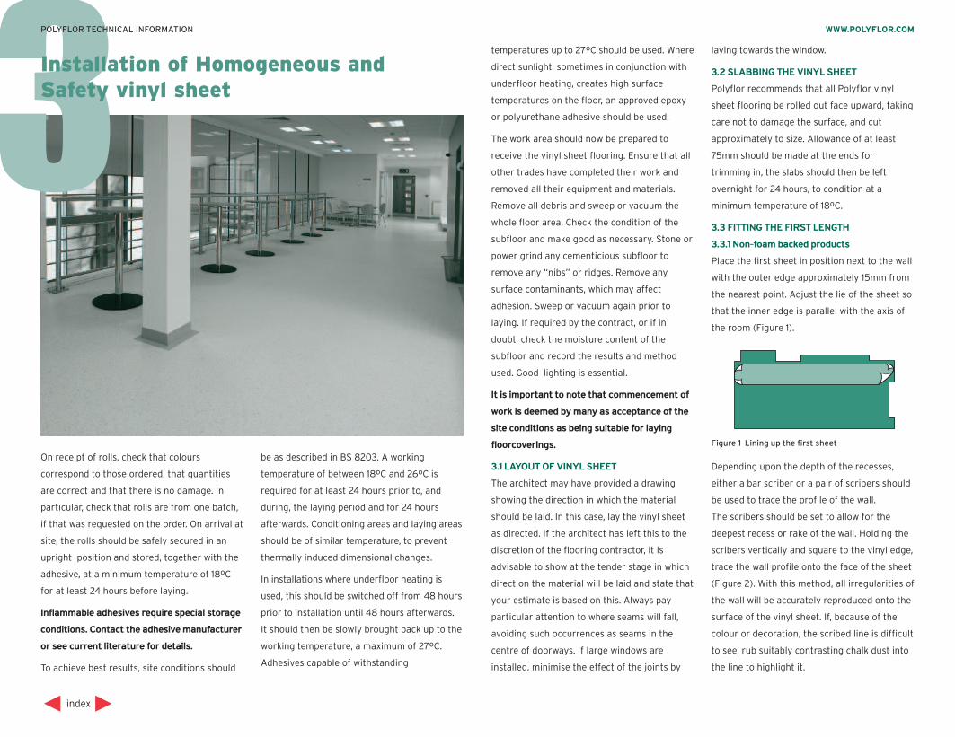
Place the first sheet in position next to the wall
with the outer edge approximately 15mm from
the nearest point. Adjust the lie of the sheet so
that the inner edge is parallel with the axis of
the room (Figure 1).
Depending upon the depth of the recesses,
either a bar scriber or a pair of scribers should
be used to trace the profile of the wall.
The scribers should be set to allow for the
deepest recess or rake of the wall. Holding the
scribers vertically and square to the vinyl edge,
trace the wall profile onto the face of the sheet
(Figure 2). With this method, all irregularities of
the wall will be accurately reproduced onto the
surface of the vinyl sheet. If, because of the
colour or decoration, the scribed line is difficult
to see, rub suitably contrasting chalk dust into
the line to highlight it.
index
WWW.POLYFLOR.COMPOLYFLOR TECHNICAL INFORMATION
Installation of Homogeneous and Safety vinyl sheet
Figure 1 Lining up the first sheet
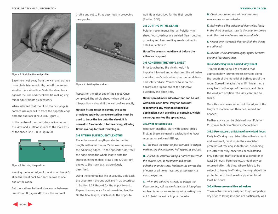
Ease the sheet away from the wall and, using a
hook blade trimming knife, cut off the excess
vinyl to the scribed line. Slide the sheet back
against the wall and check the fit, making any
minor adjustments as necessary.
When satisfied that the fit on the first edge is
correct, use a pencil to trace the opposite edge
onto the subfloor (line A-B in Figure 3).
In the centre of the room, draw a line on both
the vinyl and subfloor square to the main axis
of the sheet (line C-D in Figure 3).
Keeping the inner edge of the vinyl on line A-B,
slide the sheet back to clear the wall at one
end of the room.
Set the scribers to the distance now between
lines C and D (Figure 4). Trace the end wall
profile and cut to fit as described in preceding
paragraphs.
Repeat for the other end of the sheet. Once
completed, the whole sheet – when slid back
into position – should fit the wall profiles exactly.
Note: If fitting to set-in coving, the same
principles apply but a reverse scriber must be
used to trace the toe onto the sheet. It is
normal to free hand cut to the coving, allowing
12mm overlap for final trimming in.
3.4 FITTING SUBSEQUENT LENGTHS
Place the second length parallel to the first
length, with a maximum 25mm overlap along
the adjoining edges. On the opposite side, trace
the edge along the whole length onto the
subfloor. In the middle, draw a line C-D at right
angles to the main axis, as previously
described.
Using the longitudinal line as a guide, slide back
the sheet from the end wall and fit as described
in Section 3.3.1. Repeat for the opposite end.
Repeat the sequence for all remaining lengths.
On the final length, which abuts the opposite
wall, fit as described for the first length
(Section 3.3.1).
3.5 CUTTING IN THE SEAMS
Polyflor recommends that all Polyflor vinyl
sheet floorcoverings are welded. Seam cutting,
grooving and heat welding are described in
detail in Section 12.
Note: The seams should be cut before the
adhesive is spread.
3.6 ADHERING THE VINYL SHEET
Prior to adhering the vinyl sheet, it is
important to read and understand the adhesive
manufacturer’s instructions, recommendations
and safety advice. You need to know the
hazards and limitations of the adhesive,
especially the open time.
Never spread more adhesive than can be laid
within the open time. Polyflor does not
recommend any method of adhesive
application, such as rolling or spraying, which
cannot guarantee the spread rate.
3.6.1 Wet set adhesives
Wherever practical, start with central strips
first, as these are usually easier, having fewer
recesses or awkward fittings.
A. Fold back the sheet to just over half its length,
making sure the remaining half retains its position.
B. Spread the adhesive using a notched trowel of
the correct size, as recommended by the
adhesive manufacturer. Maintain the correct size
of notch at all times, recutting as necessary as
work progresses.
C. When the adhesive is ready to accept the
floorcovering, roll the vinyl sheet back into place,
rubbing from the centre to the edge, taking care
not to twist the roll or trap air bubbles.
D. Check that seams are without gaps and
remove any excess adhesive.
E. Roll with a 68kg articulated floor roller, firstly
in the short direction, then in the long. In corners
and other awkward areas, use a hand roller.
F. Repeat over the whole floor until all the sheets
are adhered.
G. Roll the whole area thoroughly again, between
one and four hours later.
3.6.2 Adhering foam-backed vinyl sheet
Trim the material to size ensuring that
approximately 150mm excess remains along
the length of the material at both edges of the
room. Spread the adhesive until 1 linear metre
away from both edges of the room, and place
the vinyl into position. The vinyl can then be
rolled.
Once this has been carried out the edges of the
length of material can then be trimmed and
bonded.
Further advice can be obtained from Polyflor
Customer Technical Services Department.
3.6.3 Premature trafficking of newly laid floors
Early trafficking may disturb the adhesive bond
and weaken it, resulting in the associated
problems of tracking, indentation, debonding
etc. After the vinyl sheet has been installed,
only light foot traffic should be allowed for at
least 24 hours. Furniture etc. should only be
returned after this time. Where liable to be
subject to heavy trafficking, the vinyl should be
protected with hardboard or plywood for at
least 48 hours.
3.6.4 Pressure-sensitive adhesives
These adhesives are designed to go completely
dry prior to laying into and are particularly well
index
WWW.POLYFLOR.COMPOLYFLOR TECHNICAL INFORMATION
Figure 3 Marking the position
Figure 2 Scribing the wall profile
Figure 4 Setting the scriber
suited to dense subfloors where there is
difficulty with moisture uptake. They have the
advantage of very long open times but,
because they are laid into dry, have the
disadvantage that the adhesive ridges are not
flattened when the vinyl is rolled. To eliminate
this disadvantage, Polyflor recommends an
alternative method of application:
A. Fold back all the sheets to just over half their
length.
B. Spread the adhesive with the correct notch
trowel. Maintain the correct size of notch at all
times. Then roll out the adhesive ridges with a
long handled, short pile adhesive roller.
Note: To maintain the correct spread rate, the
adhesive roller should be pre-wetted with
adhesive. This will prevent it taking adhesive
from the floor.
C. Wrap the roller in a polyethylene bag and
hang up when not in use. This will prevent it from
drying out. It also prevents flats being formed and
avoids regular washing out and pre-wetting.
D. When the adhesive is completely dry and
ready to lay into, it will change from opaque to
clear or translucent. The adhesive will be tacky to
the touch. It is worth remembering that air flow
is the most critical factor in the drying time and
not temperature. Electric fans can be used to
accelerate the drying time.
E. Place a length of 100mm wide polyethylene
strip onto the edge of the adhesive adjacent to
the fold in the vinyl sheet (Figure 5).
This will prevent the sheet sticking to the last
100mm of adhesive.
F. Roll the central sheet back into place along the
longitudinal line, taking care not to twist the roll
or trap air bubbles. (A length of wide polyethylene
strip can be rolled out on top of the adhesive to
enable it to be walked on. This can be helpful
when fitting the first length up to the line. Roll it
up from the far end on completion.)
G. Fit all the other sheets, working outwards from
the central sheet, as described previously. Take
extra care to ensure that seams are without gaps
and remove any excess adhesive as work proceeds.
H. Fold back the second halves of the vinyl sheets
and remove the polyethylene strip which was
stuck to the edge of the adhesive. Repeat
sequence of adhering vinyl sheet as described
previously.
I. Roll thoroughly in both directions using a 68kg
articulated floor roller. In corners and other
awkward areas, use a hand roller. Repeat again
after 1 – 4 hours.
3.7 PATTERN TEMPLATE METHOD
Areas which call for a considerable amount of
fitting around obstacles, or which are too
confined to lay down a sheet for fitting by
normal methods, can be dealt with by
templating the floor in felt paper.
Note: In new buildings, it may be worthwhile
discussing installation with the main
contractor who may agree to fitting WCs, sinks
etc. after the vinyl has been laid.
A. Dry fit the area with felt paper, leaving a gap
of 15mm to 20mm around obstructions and walls.
B. Draw around the fittings using a compass set
at 25mm. Mark the template “This Side Up”.
C. Place the vinyl sheet in a larger area with the
face uppermost. Place the template on top
ensuring the direction of decoration is correct.
Secure the template firmly in position and, with a
pair of scribers set at 25mm, mark the position of
all obstacles using the template as a guide.
D. Using a sharp vinyl trimming knife, cut the
vinyl sheet to the scribed lines and fit into
position.
Note: Do not use the felt paper template as an
underlay.
3.8 SITE FORMED COVED SKIRTINGS
Polyflor fully flexible vinyl flooring, in
conjunction with Polyflor Ejecta cove former
(see also Section 9) can be used to create site
formed coved skirting. In shower areas, for
example, the vinyl sheet can be extended up the
wall and, when welded, will form a watertight
base. Alternatively, in hospital corridors or
office complexes, a contrasting colour can be
used for decoration or identification.
A. Adhere the sections of cove former using a
contact adhesive. Use a mitre-block to accurately
cut internal and external corners and only adjust
for length on straight cuts.
Note: The installation of Polyflor Ejecta vinyl
flooring accessories using contact adhesives is
covered in detail in Section 10.
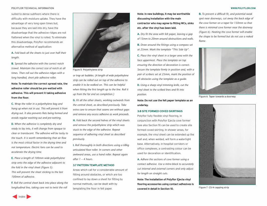
B. To prevent a difficult fit, and potential weak
spot near doorways, cut away the back edge of
the cove former on a taper for 150mm so that
there is minimal cove former near the doorway
(Figure 6). Heating the cove former will enable
the shape to be formed but do not use a naked
flame.
index
WWW.POLYFLOR.COMPOLYFLOR TECHNICAL INFORMATION
Figure 5 Polyethylene strip
Figure 6 Taper towards a doorway
Figure 7 CS-N capping strip

3.8.1 Fitting with clip-in capping strip
(Type CS-N)
A. Draw a line on the walls around the room to
the height the coving will reach.
B. Place the vinyl to the walls and then draw a
line to the same height as previous. Using a
straight edge and sharp knife, trim off the excess.
C. Pull back the sheet from the walls. Fit the
capping strip to the wall with contact adhesive
so that the top of the sheet will sit inside the cap.
D. Apply contact adhesive to the face of the cove
former and up to the capping strip. Coat the
back of the vinyl with contact adhesive and leave
both to dry.
E. When dry, push the vinyl into place and tuck
the top edge into the capping strip (Figure 7).
Roll with a hand roller to ensure even contact.
3.8.2 Fitting with sit-on capping strip
(Type CS)
A. Using a height gauge fitted with a pencil,
draw a line on the walls around the room to the
height the coving will reach.
B. Apply contact adhesive to the face of the cove
former and up to the pencil line on the wall.
Coat the back of the vinyl with contact adhesive
and leave both to dry.
C. When dry, push the vinyl into place and roll
with a hand roller to ensure even contact.
D. Reduce the height gauge to allow for the
thickness of the floorcovering and adhesive.
Draw a line on the vinyl to the same height as
previous. Using a straight edge and sharp knife,
trim off the excess.
E. Using a piece of capping strip, mark where the
strip overlaps the wall and vinyl sheet.
Apply contact adhesive between the lines and to
the back of the capping strip. When dry, push
into place (Figure 8).
Note: Welded external corners are prone to
breaking open due to damage from wheeled
traffic. To prevent this from occurring, and as
an alternative to the traditional mitre, the joint
may be cut at an angle and taken around the
corner and welded (Figure 9).
3.9 FITTING TO CERAMIC WALL TILES
For the junction between site formed coved
skirting and ceramic wall tiles, Polyflor Ejecta
CT strip should be used. The flexible section is
designed to accept ceramic tiles on one side
and various gauges of vinyl on the other.
The Polyflor CT strip should be adhered using a
contact adhesive as recommended by Polyflor.
The edge between the CT strip and the ceramic
tiles should be grouted. The Polyflor should be
fitted into the bottom edge of the CT strip and
adhered to the wall using a contact adhesive as
recommended by Polyflor. See also Section 15.
A thin bead of mastic sealant should be run
along the underside edge of the CT strip and
the Polyflor (Figure 10).
index
WWW.POLYFLOR.COMPOLYFLOR TECHNICAL INFORMATION
Figure 8 CS capping strip Figure 10 Fitting to ceramic tilesFigure 9 External corners
4Installation of Homogeneous vinyl tiles
quickly and is especially important with high
vinyl content products such as Polyflor
Prestige PUR and Polyflor Mystique PUR.
To achieve best results, site conditions should
be as described in BS 8203. A working
temperature of between 18ºC and 26ºC is
required for 24 hours prior to, and during, the
laying period and for 24 hours afterwards.
Conditioning areas and laying areas should be
of similar temperature, to prevent thermally
induced dimensional changes. In installations
where underfloor heating is used, this should
be switched off from 48 hours prior to
installation until 48 hours afterwards. It should
then be brought slowly back up to the working
temperature, a maximum of 27ºC. Adhesives
capable of withstanding temperatures up to
27ºC should be used. Where direct sunlight,
sometimes in conjunction with underfloor
heating, creates high surface temperatures on
the floor, an approved epoxy or polyurethane
adhesive should be used.
The work area should now be prepared to
receive the vinyl tiles. Ensure all other trades
have completed their work and removed all
their equipment and materials. Remove all
debris and sweep or vacuum the whole floor
area. Check the condition of the subfloor and
make good as necessary. Stone or power grind
any cementicious subfloor to remove any
“nibs” or ridges. Remove any surface
contaminants that may affect adhesion. Sweep
or vacuum again, prior to laying. If required,
check moisture content of the subfloor and
record the results and method used. Good
lighting is essential.
It is important to note that commencement of
work is deemed by many as acceptance of the
site conditions as suitable for laying
floorcoverings.
4.1 LAYOUT OF VINYL TILES
Although many floor layers regard vinyl tiles as
being easier to lay than vinyl sheet, the layout
of the tiles can be critical to the success of the
installation. The regular form of tiles, especially
when laid in contrasting colours, can accentuate
deviations in the building line, emphasising the
need for detailed planning of the layout.
Many floor layers start in the main doorway,
believing that the initial impression when
entering a room is most important. However,
working from the centre of the room and loose
laying tiles to check the layout will make the
final appearance correct from any viewpoint.
This is especially important where a geometric
design is incorporated into the floor.
4.2 MEASURING AND MARKING OUT
A.Measure the room to be laid in both
directions, including any alcoves etc.
B. Mark a chalk centreline A-B, ensuring that it is
square to the wall with the doorway.
C. Loose lay tiles away from the centreline A-B and
check that no small strips will have to be laid at
the perimeter of the room. If small strips do result,
move the centreline in either direction, keeping it
parallel to the line A-B, so that the perimeter tiles
will only require a small piece cutting off.
D.Mark a chalk centreline C-D, ensuring that it is
square to the line A-B. Check squareness with a
large square, trammels or geometrically.
E. Loose lay tiles away from the centrelines C-D
and check that no small strips will have to be
index
WWW.POLYFLOR.COMPOLYFLOR TECHNICAL INFORMATION
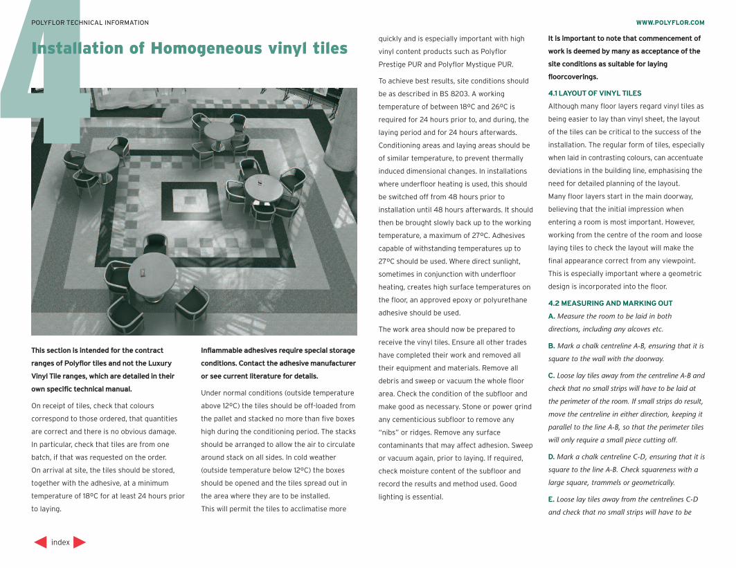
This section is intended for the contract
ranges of Polyflor tiles and not the Luxury
Vinyl Tile ranges, which are detailed in their
own specific technical manual.
On receipt of tiles, check that colours
correspond to those ordered, that quantities
are correct and there is no obvious damage.
In particular, check that tiles are from one
batch, if that was requested on the order.
On arrival at site, the tiles should be stored,
together with the adhesive, at a minimum
temperature of 18ºC for at least 24 hours prior
to laying.
Inflammable adhesives require special storage
conditions. Contact the adhesive manufacturer
or see current literature for details.
Under normal conditions (outside temperature
above 12ºC) the tiles should be off-loaded from
the pallet and stacked no more than five boxes
high during the conditioning period. The stacks
should be arranged to allow the air to circulate
around stack on all sides. In cold weather
(outside temperature below 12ºC) the boxes
should be opened and the tiles spread out in
the area where they are to be installed.
This will permit the tiles to acclimatise more
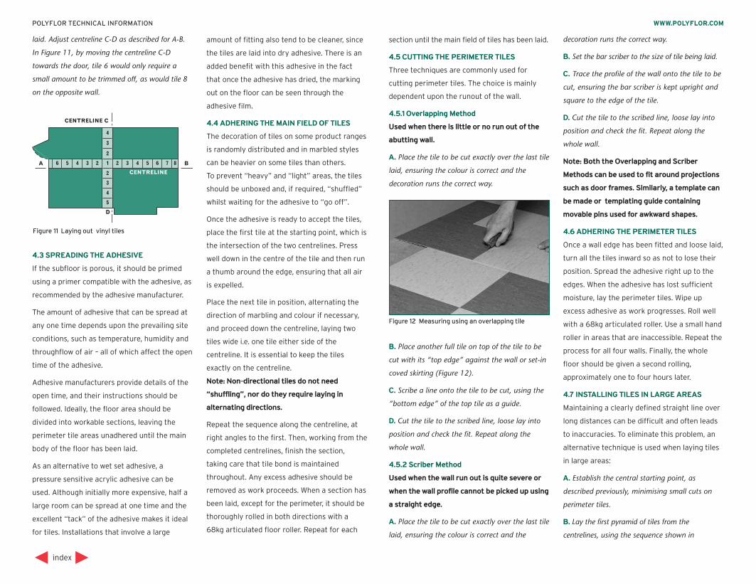
laid. Adjust centreline C-D as described for A-B.
In Figure 11, by moving the centreline C-D
towards the door, tile 6 would only require a
small amount to be trimmed off, as would tile 8
on the opposite wall.
4.3 SPREADING THE ADHESIVE
If the subfloor is porous, it should be primed
using a primer compatible with the adhesive, as
recommended by the adhesive manufacturer.
The amount of adhesive that can be spread at
any one time depends upon the prevailing site
conditions, such as temperature, humidity and
throughflow of air – all of which affect the open
time of the adhesive.
Adhesive manufacturers provide details of the
open time, and their instructions should be
followed. Ideally, the floor area should be
divided into workable sections, leaving the
perimeter tile areas unadhered until the main
body of the floor has been laid.
As an alternative to wet set adhesive, a
pressure sensitive acrylic adhesive can be
used. Although initially more expensive, half a
large room can be spread at one time and the
excellent “tack” of the adhesive makes it ideal
for tiles. Installations that involve a large
amount of fitting also tend to be cleaner, since
the tiles are laid into dry adhesive. There is an
added benefit with this adhesive in the fact
that once the adhesive has dried, the marking
out on the floor can be seen through the
adhesive film.
4.4 ADHERING THE MAIN FIELD OF TILES
The decoration of tiles on some product ranges
is randomly distributed and in marbled styles
can be heavier on some tiles than others.
To prevent “heavy” and “light” areas, the tiles
should be unboxed and, if required, “shuffled”
whilst waiting for the adhesive to “go off”.
Once the adhesive is ready to accept the tiles,
place the first tile at the starting point, which is
the intersection of the two centrelines. Press
well down in the centre of the tile and then run
a thumb around the edge, ensuring that all air
is expelled.
Place the next tile in position, alternating the
direction of marbling and colour if necessary,
and proceed down the centreline, laying two
tiles wide i.e. one tile either side of the
centreline. It is essential to keep the tiles
exactly on the centreline.
Note: Non-directional tiles do not need
“shuffling”, nor do they require laying in
alternating directions.
Repeat the sequence along the centreline, at
right angles to the first. Then, working from the
completed centrelines, finish the section,
taking care that tile bond is maintained
throughout. Any excess adhesive should be
removed as work proceeds. When a section has
been laid, except for the perimeter, it should be
thoroughly rolled in both directions with a
68kg articulated floor roller. Repeat for each
section until the main field of tiles has been laid.
4.5 CUTTING THE PERIMETER TILES
Three techniques are commonly used for
cutting perimeter tiles. The choice is mainly
dependent upon the runout of the wall.
4.5.1 Overlapping Method
Used when there is little or no run out of the
abutting wall.
A. Place the tile to be cut exactly over the last tile
laid, ensuring the colour is correct and the
decoration runs the correct way.
B. Place another full tile on top of the tile to be
cut with its “top edge” against the wall or set-in
coved skirting (Figure 12).
C. Scribe a line onto the tile to be cut, using the
“bottom edge” of the top tile as a guide.
D. Cut the tile to the scribed line, loose lay into
position and check the fit. Repeat along the
whole wall.
4.5.2 Scriber Method
Used when the wall run out is quite severe or
when the wall profile cannot be picked up using
a straight edge.
A. Place the tile to be cut exactly over the last tile
laid, ensuring the colour is correct and the
decoration runs the correct way.
B. Set the bar scriber to the size of tile being laid.
C. Trace the profile of the wall onto the tile to be
cut, ensuring the bar scriber is kept upright and
square to the edge of the tile.
D. Cut the tile to the scribed line, loose lay into
position and check the fit. Repeat along the
whole wall.
Note: Both the Overlapping and Scriber
Methods can be used to fit around projections
such as door frames. Similarly, a template can
be made or templating guide containing
movable pins used for awkward shapes.
4.6 ADHERING THE PERIMETER TILES
Once a wall edge has been fitted and loose laid,
turn all the tiles inward so as not to lose their
position. Spread the adhesive right up to the
edges. When the adhesive has lost sufficient
moisture, lay the perimeter tiles. Wipe up
excess adhesive as work progresses. Roll well
with a 68kg articulated roller. Use a small hand
roller in areas that are inaccessible. Repeat the
process for all four walls. Finally, the whole
floor should be given a second rolling,
approximately one to four hours later.
4.7 INSTALLING TILES IN LARGE AREAS
Maintaining a clearly defined straight line over
long distances can be difficult and often leads
to inaccuracies. To eliminate this problem, an
alternative technique is used when laying tiles
in large areas:
A. Establish the central starting point, as
described previously, minimising small cuts on
perimeter tiles.
B. Lay the first pyramid of tiles from the
centrelines, using the sequence shown in
index
WWW.POLYFLOR.COMPOLYFLOR TECHNICAL INFORMATION
Figure 12 Measuring using an overlapping tile
Figure 11 Laying out vinyl tiles

Figure 13. Ensure a close bond is maintained at
all times.
C. Repeat this sequence on the opposite side of
the centreline shown as area 2 in Figure 14.
Continue working in larger and larger pyramids,
as shown in Figure 14, until only the perimeter
tiles require fitting.
Note: Construction of a pyramid should always
start at the centre of the baseline, working in
the same sequence as shown in Figure 13.
D. Fit the perimeter tiles as described in
Section 4.5.
4.8 WELDING OF TILES
Polyflor recommend that all 608mm tile
installations be heat welded, as undulations in
the subfloor can cause the tiles to go out of
bond, resulting in slight but unacceptable gaps.
Heat welding is described in Section 12.
The use of a contrasting weld rod can be used
to create simple design effects. To calculate
how much weld rod is required for the
installation, multiply the number of square
metres laid by 3.3, to give you the number of
linear metres of weld rod.
index
WWW.POLYFLOR.COMPOLYFLOR TECHNICAL INFORMATION
Figure 13 Pyramid layout
Figure 14 Floor layout
5
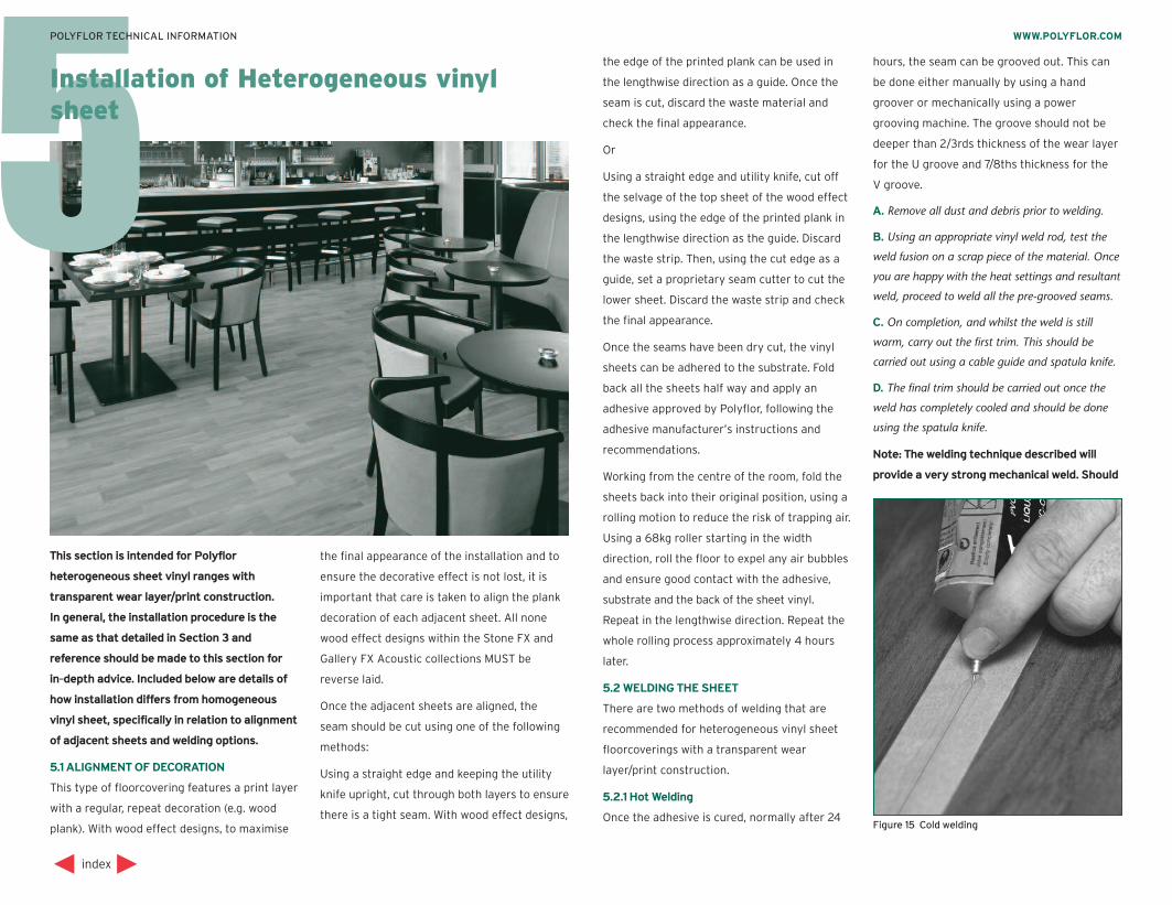
This section is intended for Polyflor
heterogeneous sheet vinyl ranges with
transparent wear layer/print construction.
In general, the installation procedure is the
same as that detailed in Section 3 and
reference should be made to this section for
in-depth advice. Included below are details of
how installation differs from homogeneous
vinyl sheet, specifically in relation to alignment
of adjacent sheets and welding options.
5.1 ALIGNMENT OF DECORATION
This type of floorcovering features a print layer
with a regular, repeat decoration (e.g. wood
plank). With wood effect designs, to maximise
the final appearance of the installation and to
ensure the decorative effect is not lost, it is
important that care is taken to align the plank
decoration of each adjacent sheet. All none
wood effect designs within the Stone FX and
Gallery FX Acoustic collections MUST be
reverse laid.
Once the adjacent sheets are aligned, the
seam should be cut using one of the following
methods:
Using a straight edge and keeping the utility
knife upright, cut through both layers to ensure
there is a tight seam. With wood effect designs,
the edge of the printed plank can be used in
the lengthwise direction as a guide. Once the
seam is cut, discard the waste material and
check the final appearance.
Or
Using a straight edge and utility knife, cut off
the selvage of the top sheet of the wood effect
designs, using the edge of the printed plank in
the lengthwise direction as the guide. Discard
the waste strip. Then, using the cut edge as a
guide, set a proprietary seam cutter to cut the
lower sheet. Discard the waste strip and check
the final appearance.
Once the seams have been dry cut, the vinyl
sheets can be adhered to the substrate. Fold
back all the sheets half way and apply an
adhesive approved by Polyflor, following the
adhesive manufacturer’s instructions and
recommendations.
Working from the centre of the room, fold the
sheets back into their original position, using a
rolling motion to reduce the risk of trapping air.
Using a 68kg roller starting in the width
direction, roll the floor to expel any air bubbles
and ensure good contact with the adhesive,
substrate and the back of the sheet vinyl.
Repeat in the lengthwise direction. Repeat the
whole rolling process approximately 4 hours
later.
5.2 WELDING THE SHEET
There are two methods of welding that are
recommended for heterogeneous vinyl sheet
floorcoverings with a transparent wear
layer/print construction.
5.2.1 Hot Welding
Once the adhesive is cured, normally after 24
hours, the seam can be grooved out. This can
be done either manually by using a hand
groover or mechanically using a power
grooving machine. The groove should not be
deeper than 2/3rds thickness of the wear layer
for the U groove and 7/8ths thickness for the
V groove.
A. Remove all dust and debris prior to welding.
B. Using an appropriate vinyl weld rod, test the
weld fusion on a scrap piece of the material. Once
you are happy with the heat settings and resultant
weld, proceed to weld all the pre-grooved seams.
C. On completion, and whilst the weld is still
warm, carry out the first trim. This should be
carried out using a cable guide and spatula knife.
D. The final trim should be carried out once the
weld has completely cooled and should be done
using the spatula knife.
Note: The welding technique described will
provide a very strong mechanical weld. Should
index
WWW.POLYFLOR.COMPOLYFLOR TECHNICAL INFORMATION
Installation of Heterogeneous vinylsheet
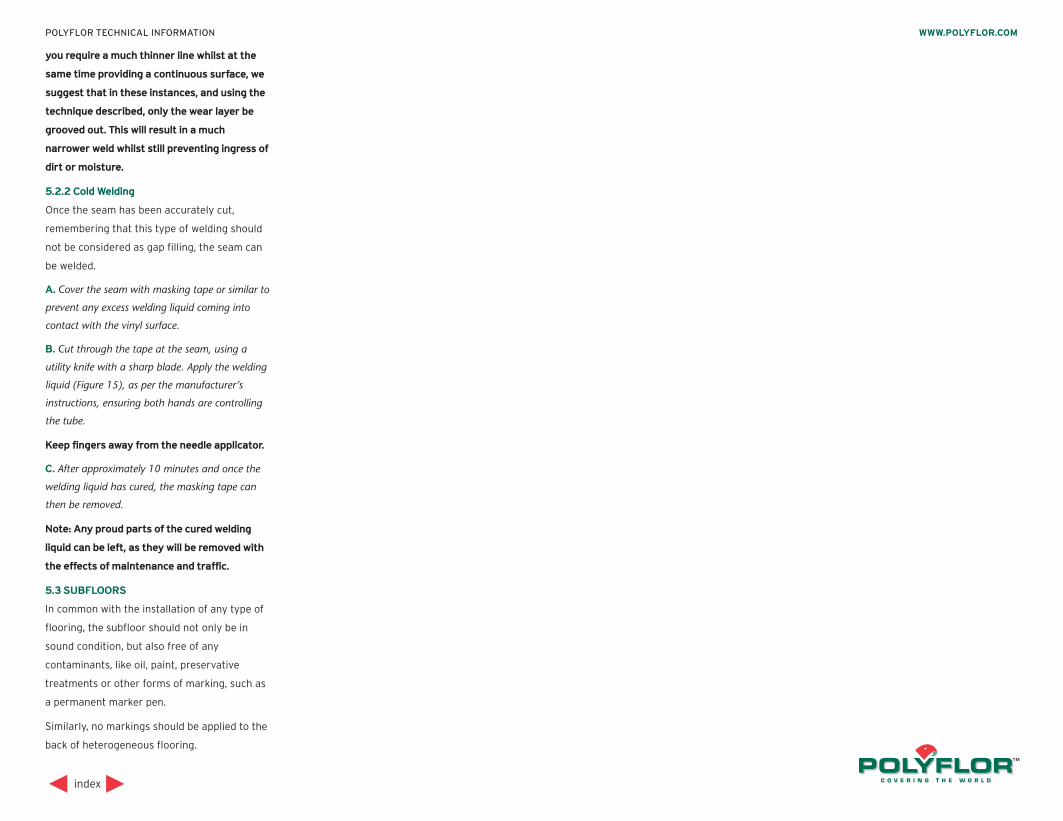
Figure 15 Cold welding
you require a much thinner line whilst at the
same time providing a continuous surface, we
suggest that in these instances, and using the
technique described, only the wear layer be
grooved out. This will result in a much
narrower weld whilst still preventing ingress of
dirt or moisture.
5.2.2 Cold Welding
Once the seam has been accurately cut,
remembering that this type of welding should
not be considered as gap filling, the seam can
be welded.
A. Cover the seam with masking tape or similar to
prevent any excess welding liquid coming into
contact with the vinyl surface.
B. Cut through the tape at the seam, using a
utility knife with a sharp blade. Apply the welding
liquid (Figure 15), as per the manufacturer’s
instructions, ensuring both hands are controlling
the tube.
Keep fingers away from the needle applicator.
C. After approximately 10 minutes and once the
welding liquid has cured, the masking tape can
then be removed.
Note: Any proud parts of the cured welding
liquid can be left, as they will be removed with
the effects of maintenance and traffic.
5.3 SUBFLOORS
In common with the installation of any type of
flooring, the subfloor should not only be in
sound condition, but also free of any
contaminants, like oil, paint, preservative
treatments or other forms of marking, such as
a permanent marker pen.
Similarly, no markings should be applied to the
back of heterogeneous flooring.
index
WWW.POLYFLOR.COMPOLYFLOR TECHNICAL INFORMATION
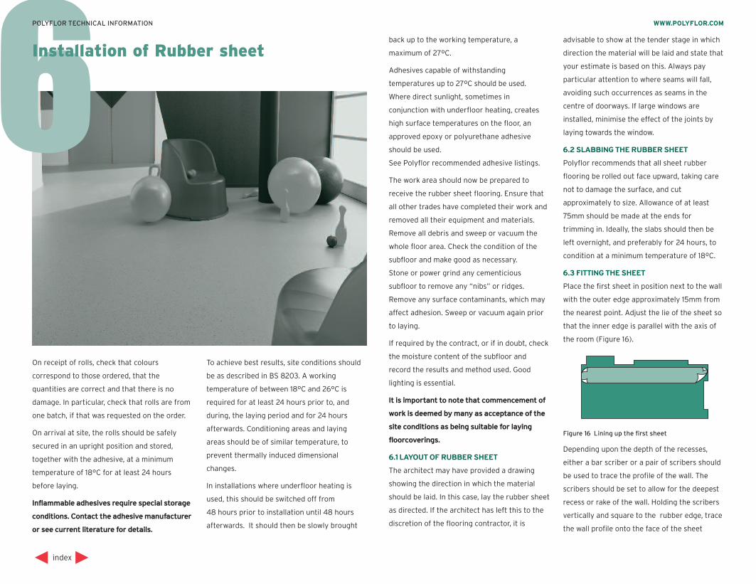
6
On receipt of rolls, check that colours
correspond to those ordered, that the
quantities are correct and that there is no
damage. In particular, check that rolls are from
one batch, if that was requested on the order.
On arrival at site, the rolls should be safely
secured in an upright position and stored,
together with the adhesive, at a minimum
temperature of 18°C for at least 24 hours
before laying.
Inflammable adhesives require special storage
conditions. Contact the adhesive manufacturer
or see current literature for details.
To achieve best results, site conditions should
be as described in BS 8203. A working
temperature of between 18°C and 26°C is
required for at least 24 hours prior to, and
during, the laying period and for 24 hours
afterwards. Conditioning areas and laying
areas should be of similar temperature, to
prevent thermally induced dimensional
changes.
In installations where underfloor heating is
used, this should be switched off from
48 hours prior to installation until 48 hours
afterwards. It should then be slowly brought
back up to the working temperature, a
maximum of 27ºC.
Adhesives capable of withstanding
temperatures up to 27ºC should be used.
Where direct sunlight, sometimes in
conjunction with underfloor heating, creates
high surface temperatures on the floor, an
approved epoxy or polyurethane adhesive
should be used.
See Polyflor recommended adhesive listings.
The work area should now be prepared to
receive the rubber sheet flooring. Ensure that
all other trades have completed their work and
removed all their equipment and materials.
Remove all debris and sweep or vacuum the
whole floor area. Check the condition of the
subfloor and make good as necessary.
Stone or power grind any cementicious
subfloor to remove any “nibs” or ridges.
Remove any surface contaminants, which may
affect adhesion. Sweep or vacuum again prior
to laying.
If required by the contract, or if in doubt, check
the moisture content of the subfloor and
record the results and method used. Good
lighting is essential.
It is important to note that commencement of
work is deemed by many as acceptance of the
site conditions as being suitable for laying
floorcoverings.
6.1 LAYOUT OF RUBBER SHEET
The architect may have provided a drawing
showing the direction in which the material
should be laid. In this case, lay the rubber sheet
as directed. If the architect has left this to the
discretion of the flooring contractor, it is
advisable to show at the tender stage in which
direction the material will be laid and state that
your estimate is based on this. Always pay
particular attention to where seams will fall,
avoiding such occurrences as seams in the
centre of doorways. If large windows are
installed, minimise the effect of the joints by
laying towards the window.
6.2 SLABBING THE RUBBER SHEET
Polyflor recommends that all sheet rubber
flooring be rolled out face upward, taking care
not to damage the surface, and cut
approximately to size. Allowance of at least
75mm should be made at the ends for
trimming in. Ideally, the slabs should then be
left overnight, and preferably for 24 hours, to
condition at a minimum temperature of 18ºC.
6.3 FITTING THE SHEET
Place the first sheet in position next to the wall
with the outer edge approximately 15mm from
the nearest point. Adjust the lie of the sheet so
that the inner edge is parallel with the axis of
the room (Figure 16).
Depending upon the depth of the recesses,
either a bar scriber or a pair of scribers should
be used to trace the profile of the wall. The
scribers should be set to allow for the deepest
recess or rake of the wall. Holding the scribers
vertically and square to the rubber edge, trace
the wall profile onto the face of the sheet
index
WWW.POLYFLOR.COMPOLYFLOR TECHNICAL INFORMATION
Installation of Rubber sheet
Figure 16 Lining up the first sheet
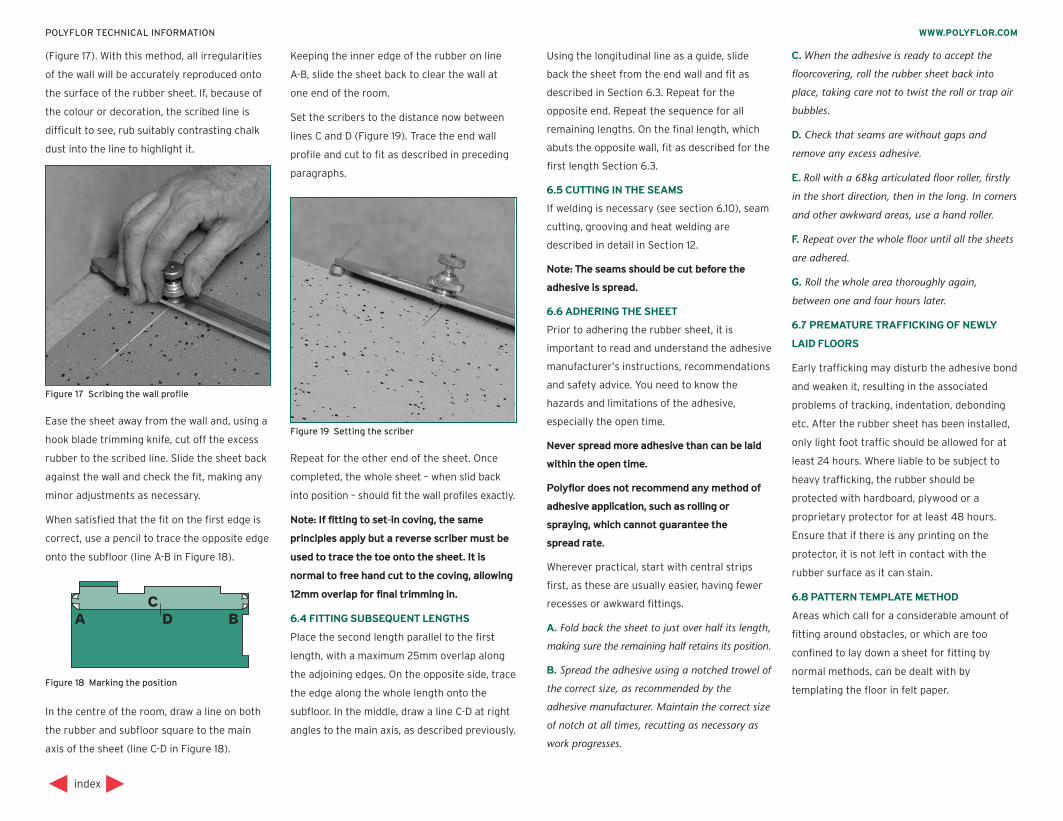
(Figure 17). With this method, all irregularities
of the wall will be accurately reproduced onto
the surface of the rubber sheet. If, because of
the colour or decoration, the scribed line is
difficult to see, rub suitably contrasting chalk
dust into the line to highlight it.
Ease the sheet away from the wall and, using a
hook blade trimming knife, cut off the excess
rubber to the scribed line. Slide the sheet back
against the wall and check the fit, making any
minor adjustments as necessary.
When satisfied that the fit on the first edge is
correct, use a pencil to trace the opposite edge
onto the subfloor (line A-B in Figure 18).
In the centre of the room, draw a line on both
the rubber and subfloor square to the main
axis of the sheet (line C-D in Figure 18).
Keeping the inner edge of the rubber on line
A-B, slide the sheet back to clear the wall at
one end of the room.
Set the scribers to the distance now between
lines C and D (Figure 19). Trace the end wall
profile and cut to fit as described in preceding
paragraphs.
Repeat for the other end of the sheet. Once
completed, the whole sheet – when slid back
into position – should fit the wall profiles exactly.
Note: If fitting to set-in coving, the same
principles apply but a reverse scriber must be
used to trace the toe onto the sheet. It is
normal to free hand cut to the coving, allowing
12mm overlap for final trimming in.
6.4 FITTING SUBSEQUENT LENGTHS
Place the second length parallel to the first
length, with a maximum 25mm overlap along
the adjoining edges. On the opposite side, trace
the edge along the whole length onto the
subfloor. In the middle, draw a line C-D at right
angles to the main axis, as described previously.
Using the longitudinal line as a guide, slide
back the sheet from the end wall and fit as
described in Section 6.3. Repeat for the
opposite end. Repeat the sequence for all
remaining lengths. On the final length, which
abuts the opposite wall, fit as described for the
first length Section 6.3.
6.5 CUTTING IN THE SEAMS
If welding is necessary (see section 6.10), seam
cutting, grooving and heat welding are
described in detail in Section 12.
Note: The seams should be cut before the
adhesive is spread.
6.6 ADHERING THE SHEET
Prior to adhering the rubber sheet, it is
important to read and understand the adhesive
manufacturer’s instructions, recommendations
and safety advice. You need to know the
hazards and limitations of the adhesive,
especially the open time.
Never spread more adhesive than can be laid
within the open time.
Polyflor does not recommend any method of
adhesive application, such as rolling or
spraying, which cannot guarantee the
spread rate.
Wherever practical, start with central strips
first, as these are usually easier, having fewer
recesses or awkward fittings.
A. Fold back the sheet to just over half its length,
making sure the remaining half retains its position.
B. Spread the adhesive using a notched trowel of
the correct size, as recommended by the
adhesive manufacturer. Maintain the correct size
of notch at all times, recutting as necessary as
work progresses.
C. When the adhesive is ready to accept the
floorcovering, roll the rubber sheet back into
place, taking care not to twist the roll or trap air
bubbles.
D. Check that seams are without gaps and
remove any excess adhesive.
E. Roll with a 68kg articulated floor roller, firstly
in the short direction, then in the long. In corners
and other awkward areas, use a hand roller.
F. Repeat over the whole floor until all the sheets
are adhered.
G. Roll the whole area thoroughly again,
between one and four hours later.
6.7 PREMATURE TRAFFICKING OF NEWLY
LAID FLOORS
Early trafficking may disturb the adhesive bond
and weaken it, resulting in the associated
problems of tracking, indentation, debonding
etc. After the rubber sheet has been installed,
only light foot traffic should be allowed for at
least 24 hours. Where liable to be subject to
heavy trafficking, the rubber should be
protected with hardboard, plywood or a
proprietary protector for at least 48 hours.
Ensure that if there is any printing on the
protector, it is not left in contact with the
rubber surface as it can stain.
6.8 PATTERN TEMPLATE METHOD
Areas which call for a considerable amount of
fitting around obstacles, or which are too
confined to lay down a sheet for fitting by
normal methods, can be dealt with by
templating the floor in felt paper.
index
WWW.POLYFLOR.COMPOLYFLOR TECHNICAL INFORMATION
Figure 18 Marking the position
Figure 17 Scribing the wall profile
Figure 19 Setting the scriber
Note: In new buildings, it may be worthwhile
discussing installation with the main
contractor who may agree to fitting WCs, sinks
etc. after the rubber has been laid.
A. Dry fit the area with felt paper, leaving a gap
of 15mm to 20mm around obstructions.
B. Draw around the fittings using a compass set
at 25mm. Mark the template “This Side Up”.
C. Place the rubber sheet in a larger area with
the face uppermost. Place the template on top
ensuring the direction of decoration is correct.
Secure the template firmly in position and, with a
pair of scribers set at 25mm, mark the position of
all obstacles using the template as a guide.
D. Using a sharp trimming knife, cut the rubber
sheet to the scribed lines and fit into position.
Do not use the felt paper template as an
underlay.
6.9 SITE FORMED COVED SKIRTING
Polyflor sheet rubber flooring, in conjunction
with a rubber cove, can be used to create site
formed coved skirting. In hospital corridors or
office complexes etc, a contrasting colour can
be used for decoration or identification.
A. Adhere the sections of cove former using a
contact adhesive.
B. Use a mitre-block to accurately cut internal
and external corners. Only adjust for length on
straight cuts.
C. To prevent a difficult fit, and potential weak
spot near doorways, cut away the back edge of
the cove former on a taper for 150mm so that
there is minimal cove former near the doorway.
Warming the cove former may help enable the
shape to be formed but do not use a naked flame.
6.10 WELDING OF RUBBER SHEET
Welding of rubber sheet is not a prerequisite in
most installations. However where there is
heavy wet cleaning or where due to hygiene
requirements a continuous smooth surface is
demanded, the joints should be heat welded
using the recommended weld rod.
index
WWW.POLYFLOR.COMPOLYFLOR TECHNICAL INFORMATION
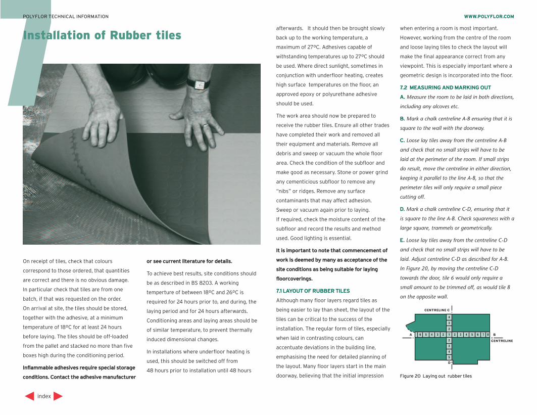
7afterwards. It should then be brought slowly
back up to the working temperature, a
maximum of 27ºC. Adhesives capable of
withstanding temperatures up to 27ºC should
be used. Where direct sunlight, sometimes in
conjunction with underfloor heating, creates
high surface temperatures on the floor, an
approved epoxy or polyurethane adhesive
should be used.
The work area should now be prepared to
receive the rubber tiles. Ensure all other trades
have completed their work and removed all
their equipment and materials. Remove all
debris and sweep or vacuum the whole floor
area. Check the condition of the subfloor and
make good as necessary. Stone or power grind
any cementicious subfloor to remove any
“nibs” or ridges. Remove any surface
contaminants that may affect adhesion.
Sweep or vacuum again prior to laying.
If required, check the moisture content of the
subfloor and record the results and method
used. Good lighting is essential.
It is important to note that commencement of
work is deemed by many as acceptance of the
site conditions as being suitable for laying
floorcoverings.
7.1 LAYOUT OF RUBBER TILES
Although many floor layers regard tiles as
being easier to lay than sheet, the layout of the
tiles can be critical to the success of the
installation. The regular form of tiles, especially
when laid in contrasting colours, can
accentuate deviations in the building line,
emphasising the need for detailed planning of
the layout. Many floor layers start in the main
doorway, believing that the initial impression
when entering a room is most important.
However, working from the centre of the room
and loose laying tiles to check the layout will
make the final appearance correct from any
viewpoint. This is especially important where a
geometric design is incorporated into the floor.
7.2 MEASURING AND MARKING OUT
A. Measure the room to be laid in both directions,
including any alcoves etc.
B. Mark a chalk centreline A-B ensuring that it is
square to the wall with the doorway.
C. Loose lay tiles away from the centreline A-B
and check that no small strips will have to be
laid at the perimeter of the room. If small strips
do result, move the centreline in either direction,
keeping it parallel to the line A-B, so that the
perimeter tiles will only require a small piece
cutting off.
D. Mark a chalk centreline C-D, ensuring that it
is square to the line A-B. Check squareness with a
large square, trammels or geometrically.
E. Loose lay tiles away from the centreline C-D
and check that no small strips will have to be
laid. Adjust centreline C-D as described for A-B.
In Figure 20, by moving the centreline C-D
towards the door, tile 6 would only require a
small amount to be trimmed off, as would tile 8
on the opposite wall.
index
WWW.POLYFLOR.COMPOLYFLOR TECHNICAL INFORMATION
Installation of Rubber tiles
On receipt of tiles, check that colours
correspond to those ordered, that quantities
are correct and there is no obvious damage.
In particular check that tiles are from one
batch, if that was requested on the order.
On arrival at site, the tiles should be stored,
together with the adhesive, at a minimum
temperature of 18ºC for at least 24 hours
before laying. The tiles should be off-loaded
from the pallet and stacked no more than five
boxes high during the conditioning period.
Inflammable adhesives require special storage
conditions. Contact the adhesive manufacturer
or see current literature for details.
To achieve best results, site conditions should
be as described in BS 8203. A working
temperture of between 18ºC and 26ºC is
required for 24 hours prior to, and during, the
laying period and for 24 hours afterwards.
Conditioning areas and laying areas should be
of similar temperature, to prevent thermally
induced dimensional changes.
In installations where underfloor heating is
used, this should be switched off from
48 hours prior to installation until 48 hoursFigure 20 Laying out rubber tiles
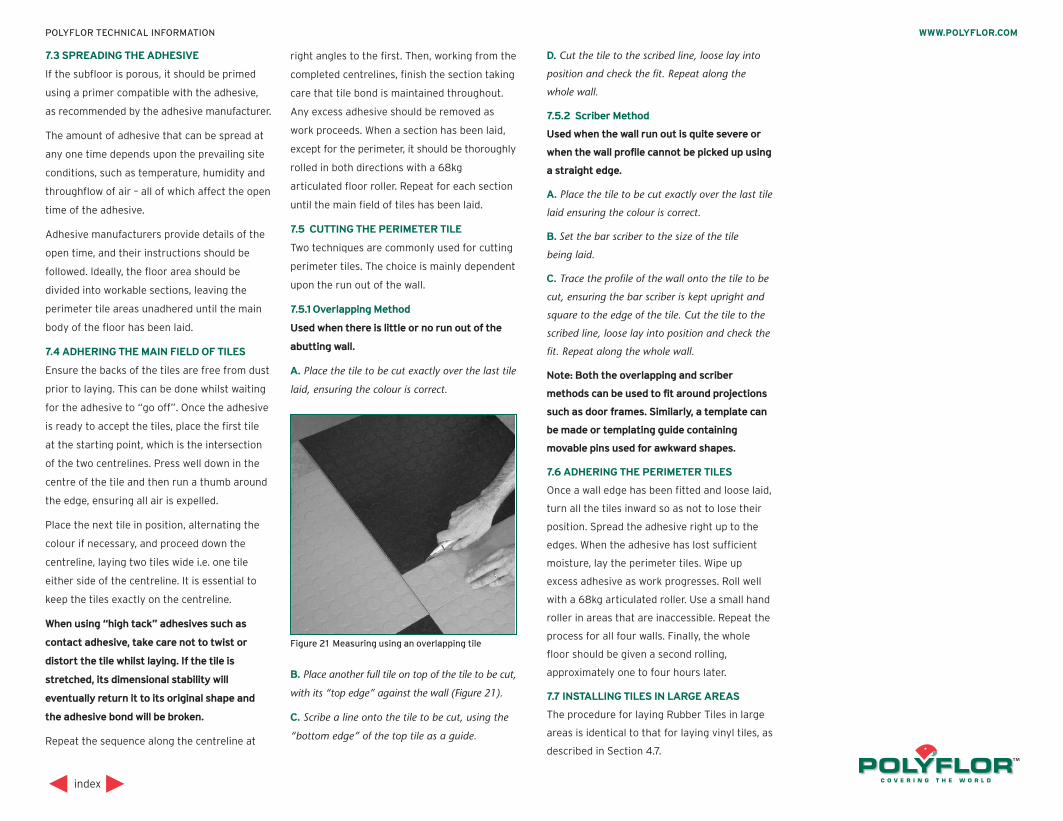
7.3 SPREADING THE ADHESIVE
If the subfloor is porous, it should be primed
using a primer compatible with the adhesive,
as recommended by the adhesive manufacturer.
The amount of adhesive that can be spread at
any one time depends upon the prevailing site
conditions, such as temperature, humidity and
throughflow of air – all of which affect the open
time of the adhesive.
Adhesive manufacturers provide details of the
open time, and their instructions should be
followed. Ideally, the floor area should be
divided into workable sections, leaving the
perimeter tile areas unadhered until the main
body of the floor has been laid.
7.4 ADHERING THE MAIN FIELD OF TILES
Ensure the backs of the tiles are free from dust
prior to laying. This can be done whilst waiting
for the adhesive to “go off”. Once the adhesive
is ready to accept the tiles, place the first tile
at the starting point, which is the intersection
of the two centrelines. Press well down in the
centre of the tile and then run a thumb around
the edge, ensuring all air is expelled.
Place the next tile in position, alternating the
colour if necessary, and proceed down the
centreline, laying two tiles wide i.e. one tile
either side of the centreline. It is essential to
keep the tiles exactly on the centreline.
When using “high tack” adhesives such as
contact adhesive, take care not to twist or
distort the tile whilst laying. If the tile is
stretched, its dimensional stability will
eventually return it to its original shape and
the adhesive bond will be broken.
Repeat the sequence along the centreline at
right angles to the first. Then, working from the
completed centrelines, finish the section taking
care that tile bond is maintained throughout.
Any excess adhesive should be removed as
work proceeds. When a section has been laid,
except for the perimeter, it should be thoroughly
rolled in both directions with a 68kg
articulated floor roller. Repeat for each section
until the main field of tiles has been laid.
7.5 CUTTING THE PERIMETER TILE
Two techniques are commonly used for cutting
perimeter tiles. The choice is mainly dependent
upon the run out of the wall.
7.5.1 Overlapping Method
Used when there is little or no run out of the
abutting wall.
A. Place the tile to be cut exactly over the last tile
laid, ensuring the colour is correct.
B. Place another full tile on top of the tile to be cut,
with its “top edge” against the wall (Figure 21).
C. Scribe a line onto the tile to be cut, using the
“bottom edge” of the top tile as a guide.
D. Cut the tile to the scribed line, loose lay into
position and check the fit. Repeat along the
whole wall.
7.5.2 Scriber Method
Used when the wall run out is quite severe or
when the wall profile cannot be picked up using
a straight edge.
A. Place the tile to be cut exactly over the last tile
laid ensuring the colour is correct.
B. Set the bar scriber to the size of the tile
being laid.
C. Trace the profile of the wall onto the tile to be
cut, ensuring the bar scriber is kept upright and
square to the edge of the tile. Cut the tile to the
scribed line, loose lay into position and check the
fit. Repeat along the whole wall.
Note: Both the overlapping and scriber
methods can be used to fit around projections
such as door frames. Similarly, a template can
be made or templating guide containing
movable pins used for awkward shapes.
7.6 ADHERING THE PERIMETER TILES
Once a wall edge has been fitted and loose laid,
turn all the tiles inward so as not to lose their
position. Spread the adhesive right up to the
edges. When the adhesive has lost sufficient
moisture, lay the perimeter tiles. Wipe up
excess adhesive as work progresses. Roll well
with a 68kg articulated roller. Use a small hand
roller in areas that are inaccessible. Repeat the
process for all four walls. Finally, the whole
floor should be given a second rolling,
approximately one to four hours later.
7.7 INSTALLING TILES IN LARGE AREAS
The procedure for laying Rubber Tiles in large
areas is identical to that for laying vinyl tiles, as
described in Section 4.7.
index
WWW.POLYFLOR.COMPOLYFLOR TECHNICAL INFORMATION
Figure 21 Measuring using an overlapping tile
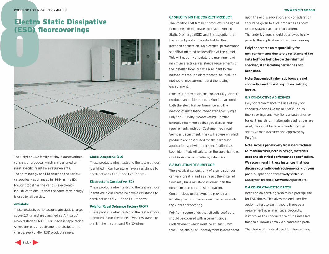
88.1 SPECIFYING THE CORRECT PRODUCT
The Polyflor ESD family of products is designed
to minimise or eliminate the risk of Electro
Static Discharge (ESD) and it is essential that
the correct product be selected for the
intended application. An electrical performance
specification must be identified at the outset.
This will not only stipulate the maximum and
minimum electrical resistance requirements of
the installed floor, but will also identify the
method of test, the electrodes to be used, the
method of measurement and the testing
environment.
From this information, the correct Polyflor ESD
product can be identified, taking into account
both the electrical performance and the
method of installation. Whenever specifying a
Polyflor ESD vinyl floorcovering, Polyflor
strongly recommends that you discuss your
requirements with our Customer Technical
Services Department. They will advise on which
products are best suited for the particular
application, and where no specifıcation has
been identified, will advise on the specifications
used in similar installations/industries.
8.2 ISOLATION OF SUBFLOOR
The electrical conductivity of a solid subfloor
can vary greatly, and as a result the installed
floor may have resistances lower than the
minimum stated in the specification.
Cementicious underlayments provide an
isolating barrier of known resistance beneath
the vinyl floorcovering.
Polyflor recommends that all solid subfloors
should be covered with a cementicious
underlayment which must be at least 3mm
thick. The choice of underlayment is dependent
upon the end use location, and consideration
should be given to such properties as point
load resistance and protein content.
The underlayment should be allowed to dry
prior to the application of the floorcovering.
Polyflor accepts no responsibility for
non-conformance due to the resistance of the
installed floor being below the minimum
specified, if an isolating barrier has not
been used.
Note: Suspended timber subfloors are not
conductive and do not require an isolating
barrier.
8.3 CONDUCTIVE ADHESIVES
Polyflor recommends the use of Polyflor
conductive adhesive for all Static Control
floorcoverings and Polyflor contact adhesive
for earthing strips. If alternative adhesives are
used, they must be recommended by the
adhesive manufacturer and approved by
Polyflor.
Note: Access panels vary frommanufacturer
to manufacturer, both in design, materials
used and electrical performance specification.
We recommend in these instances that you
discuss your individual requirements with your
panel supplier or alternatively with our
Customer Technical Services Department.
8.4 CONDUCTANCE TO EARTH
Installing an earthing system is a prerequisite
for ESD floors. This gives the end user the
option to test to earth should there be a
requirement at a later stage. Secondly,
it improves the conductance of the installed
floor to a known earth via a controlled path.
The choice of material used for the earthing
index
WWW.POLYFLOR.COMPOLYFLOR TECHNICAL INFORMATION
Electro Static Dissipative(ESD) floorcoverings
The Polyflor ESD family of vinyl floorcoverings
consists of products which are designed to
meet specific resistance requirements.
The terminology used to describe the various
categories was changed in 1999, as the IEC
brought together the various electronics
industries to ensure that the same terminology
is used by all parties.
Antistatic
These products do not accumulate static charges
above 2.0 KV and are classified as ‘Antistatic’
when tested to EN1815. For specialist application
where there is a requirement to dissipate the
charge, see Polyflor ESD product ranges.
Static Dissipative (SD)
These products when tested to the test methods
identified in our literature have a resistance to
earth between 1 x 10⁶ and 1 x 10⁹ ohms.
Electrostatic Conductive (EC)
These products when tested to the test methods
identified in our literature have a resistance to
earth between 5 x 10⁴ and 1 x 10⁶ ohms.
Polyflor Royal Ordnance Factory (ROF)
These products when tested to the test methods
identified in our literature have a resistance to
earth between zero and 5 x 10⁴ ohms.
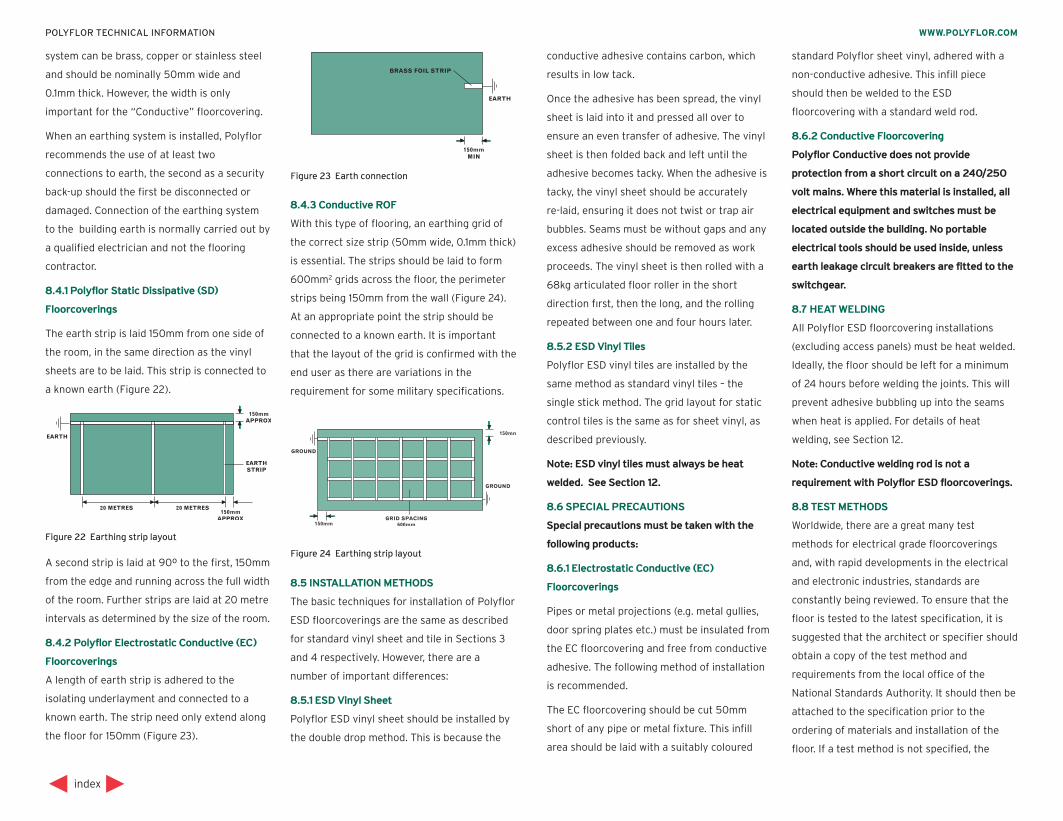
system can be brass, copper or stainless steel
and should be nominally 50mm wide and
0.1mm thick. However, the width is only
important for the “Conductive” floorcovering.
When an earthing system is installed, Polyflor
recommends the use of at least two
connections to earth, the second as a security
back-up should the first be disconnected or
damaged. Connection of the earthing system
to the building earth is normally carried out by
a qualified electrician and not the flooring
contractor.
8.4.1 Polyflor Static Dissipative (SD)
Floorcoverings
The earth strip is laid 150mm from one side of
the room, in the same direction as the vinyl
sheets are to be laid. This strip is connected to
a known earth (Figure 22).
A second strip is laid at 90º to the first, 150mm
from the edge and running across the full width
of the room. Further strips are laid at 20 metre
intervals as determined by the size of the room.
8.4.2 Polyflor Electrostatic Conductive (EC)
Floorcoverings
A length of earth strip is adhered to the
isolating underlayment and connected to a
known earth. The strip need only extend along
the floor for 150mm (Figure 23).
8.4.3 Conductive ROF
With this type of flooring, an earthing grid of
the correct size strip (50mm wide, 0.1mm thick)
is essential. The strips should be laid to form
600mm2 grids across the floor, the perimeter
strips being 150mm from the wall (Figure 24).
At an appropriate point the strip should be
connected to a known earth. It is important
that the layout of the grid is confirmed with the
end user as there are variations in the
requirement for some military specifications.
8.5 INSTALLATION METHODS
The basic techniques for installation of Polyflor
ESD floorcoverings are the same as described
for standard vinyl sheet and tile in Sections 3
and 4 respectively. However, there are a
number of important differences:
8.5.1 ESD Vinyl Sheet
Polyflor ESD vinyl sheet should be installed by
the double drop method. This is because the
conductive adhesive contains carbon, which
results in low tack.
Once the adhesive has been spread, the vinyl
sheet is laid into it and pressed all over to
ensure an even transfer of adhesive. The vinyl
sheet is then folded back and left until the
adhesive becomes tacky. When the adhesive is
tacky, the vinyl sheet should be accurately
re-laid, ensuring it does not twist or trap air
bubbles. Seams must be without gaps and any
excess adhesive should be removed as work
proceeds. The vinyl sheet is then rolled with a
68kg articulated floor roller in the short
direction fırst, then the long, and the rolling
repeated between one and four hours later.
8.5.2 ESD Vinyl Tiles
Polyflor ESD vinyl tiles are installed by the
same method as standard vinyl tiles – the
single stick method. The grid layout for static
control tiles is the same as for sheet vinyl, as
described previously.
Note: ESD vinyl tiles must always be heat
welded. See Section 12.
8.6 SPECIAL PRECAUTIONS
Special precautions must be taken with the
following products:
8.6.1 Electrostatic Conductive (EC)
Floorcoverings
Pipes or metal projections (e.g. metal gullies,
door spring plates etc.) must be insulated from
the EC floorcovering and free from conductive
adhesive. The following method of installation
is recommended.
The EC floorcovering should be cut 50mm
short of any pipe or metal fixture. This infill
area should be laid with a suitably coloured
standard Polyflor sheet vinyl, adhered with a
non-conductive adhesive. This infill piece
should then be welded to the ESD
floorcovering with a standard weld rod.
8.6.2 Conductive Floorcovering
Polyflor Conductive does not provide
protection from a short circuit on a 240/250
volt mains. Where this material is installed, all
electrical equipment and switches must be
located outside the building. No portable
electrical tools should be used inside, unless
earth leakage circuit breakers are fitted to the
switchgear.
8.7 HEAT WELDING
All Polyflor ESD floorcovering installations
(excluding access panels) must be heat welded.
Ideally, the floor should be left for a minimum
of 24 hours before welding the joints. This will
prevent adhesive bubbling up into the seams
when heat is applied. For details of heat
welding, see Section 12.
Note: Conductive welding rod is not a
requirement with Polyflor ESD floorcoverings.
8.8 TEST METHODS
Worldwide, there are a great many test
methods for electrical grade floorcoverings
and, with rapid developments in the electrical
and electronic industries, standards are
constantly being reviewed. To ensure that the
floor is tested to the latest specification, it is
suggested that the architect or specifier should
obtain a copy of the test method and
requirements from the local office of the
National Standards Authority. It should then be
attached to the specification prior to the
ordering of materials and installation of the
floor. If a test method is not specified, the
index
WWW.POLYFLOR.COMPOLYFLOR TECHNICAL INFORMATION
Figure 22 Earthing strip layout
Figure 24 Earthing strip layout
Figure 23 Earth connection
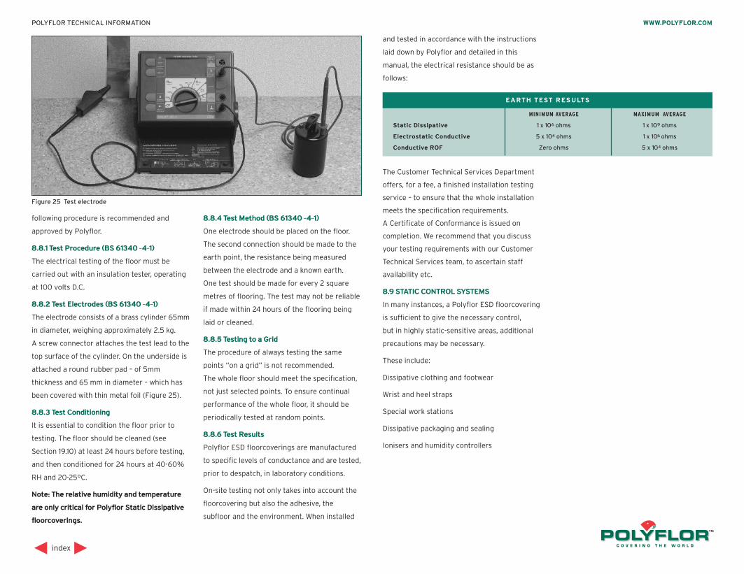
following procedure is recommended and
approved by Polyflor.
8.8.1 Test Procedure (BS 61340 -4-1)
The electrical testing of the floor must be
carried out with an insulation tester, operating
at 100 volts D.C.
8.8.2 Test Electrodes (BS 61340 -4-1)
The electrode consists of a brass cylinder 65mm
in diameter, weighing approximately 2.5 kg.
A screw connector attaches the test lead to the
top surface of the cylinder. On the underside is
attached a round rubber pad – of 5mm
thickness and 65 mm in diameter – which has
been covered with thin metal foil (Figure 25).
8.8.3 Test Conditioning
It is essential to condition the floor prior to
testing. The floor should be cleaned (see
Section 19.10) at least 24 hours before testing,
and then conditioned for 24 hours at 40-60%
RH and 20-25°C.
Note: The relative humidity and temperature
are only critical for Polyflor Static Dissipative
floorcoverings.
8.8.4 Test Method (BS 61340 -4-1)
One electrode should be placed on the floor.
The second connection should be made to the
earth point, the resistance being measured
between the electrode and a known earth.
One test should be made for every 2 square
metres of flooring. The test may not be reliable
if made within 24 hours of the flooring being
laid or cleaned.
8.8.5 Testing to a Grid
The procedure of always testing the same
points “on a grid” is not recommended.
The whole floor should meet the specifıcation,
not just selected points. To ensure continual
performance of the whole floor, it should be
periodically tested at random points.
8.8.6 Test Results
Polyflor ESD floorcoverings are manufactured
to specific levels of conductance and are tested,
prior to despatch, in laboratory conditions.
On-site testing not only takes into account the
floorcovering but also the adhesive, the
subfloor and the environment. When installed
and tested in accordance with the instructions
laid down by Polyflor and detailed in this
manual, the electrical resistance should be as
follows:
The Customer Technical Services Department
offers, for a fee, a finished installation testing
service – to ensure that the whole installation
meets the specification requirements.
A Certificate of Conformance is issued on
completion. We recommend that you discuss
your testing requirements with our Customer
Technical Services team, to ascertain staff
availability etc.
8.9 STATIC CONTROL SYSTEMS
In many instances, a Polyflor ESD floorcovering
is sufficient to give the necessary control,
but in highly static-sensitive areas, additional
precautions may be necessary.
These include:
Dissipative clothing and footwear
Wrist and heel straps
Special work stations
Dissipative packaging and sealing
Ionisers and humidity controllers
index
WWW.POLYFLOR.COMPOLYFLOR TECHNICAL INFORMATION
Figure 25 Test electrode
MINIMUM AVERAGE MAXIMUM AVERAGE
Static Dissipative 1 x 10⁶ ohms 1 x 10⁹ ohms
Electrostatic Conductive 5 x 10⁴ ohms 1 x 10⁶ ohms
Conductive ROF Zero ohms 5 x 10⁴ ohms
EARTH TEST RESULTS
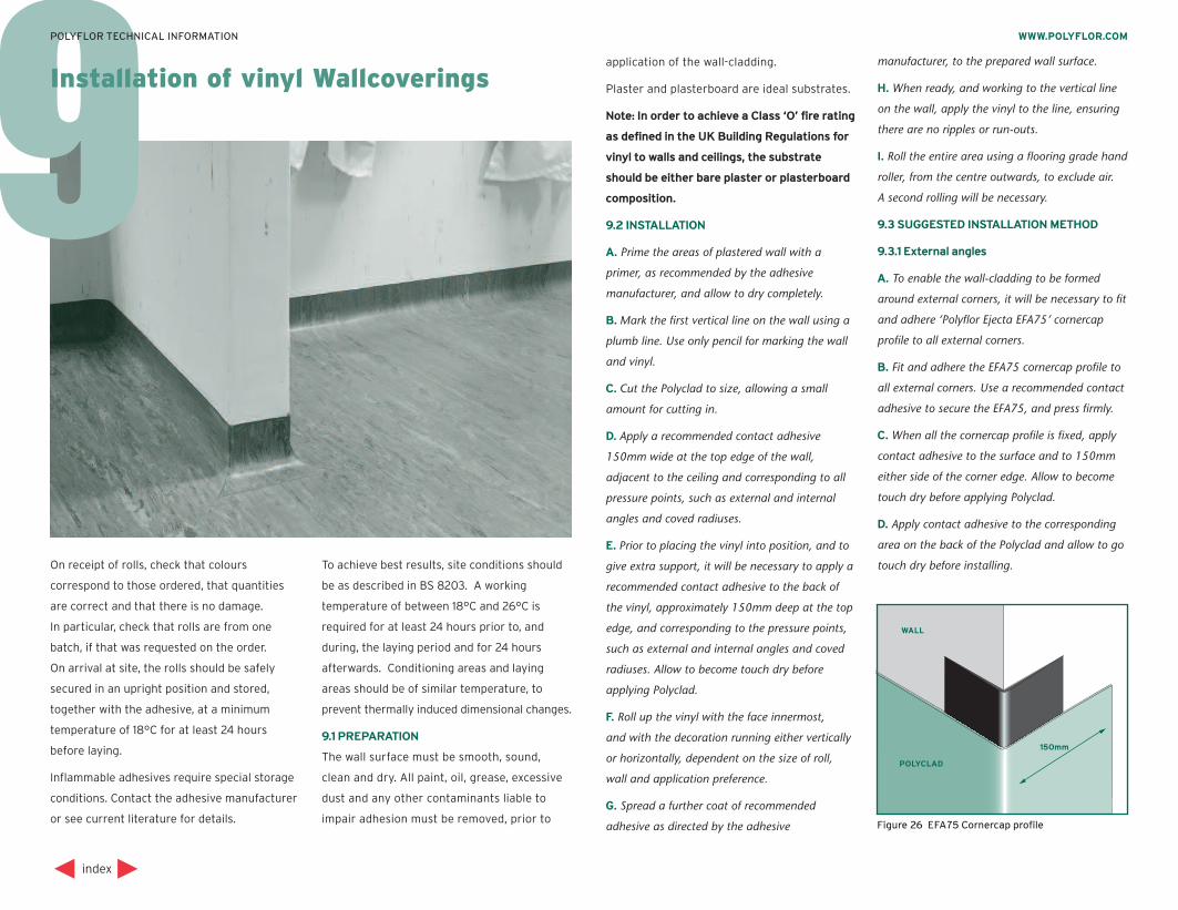
9Installation of vinyl Wallcoverings
application of the wall-cladding.
Plaster and plasterboard are ideal substrates.
Note: In order to achieve a Class ‘O’ fire rating
as defined in the UK Building Regulations for
vinyl to walls and ceilings, the substrate
should be either bare plaster or plasterboard
composition.
9.2 INSTALLATION
A. Prime the areas of plastered wall with a
primer, as recommended by the adhesive
manufacturer, and allow to dry completely.
B. Mark the first vertical line on the wall using a
plumb line. Use only pencil for marking the wall
and vinyl.
C. Cut the Polyclad to size, allowing a small
amount for cutting in.
D. Apply a recommended contact adhesive
150mm wide at the top edge of the wall,
adjacent to the ceiling and corresponding to all
pressure points, such as external and internal
angles and coved radiuses.
E. Prior to placing the vinyl into position, and to
give extra support, it will be necessary to apply a
recommended contact adhesive to the back of
the vinyl, approximately 150mm deep at the top
edge, and corresponding to the pressure points,
such as external and internal angles and coved
radiuses. Allow to become touch dry before
applying Polyclad.
F. Roll up the vinyl with the face innermost,
and with the decoration running either vertically
or horizontally, dependent on the size of roll,
wall and application preference.
G. Spread a further coat of recommended
adhesive as directed by the adhesive
manufacturer, to the prepared wall surface.
H. When ready, and working to the vertical line
on the wall, apply the vinyl to the line, ensuring
there are no ripples or run-outs.
I. Roll the entire area using a flooring grade hand
roller, from the centre outwards, to exclude air.
A second rolling will be necessary.
9.3 SUGGESTED INSTALLATION METHOD
9.3.1 External angles
A. To enable the wall-cladding to be formed
around external corners, it will be necessary to fit
and adhere ‘Polyflor Ejecta EFA75’ cornercap
profile to all external corners.
B. Fit and adhere the EFA75 cornercap profile to
all external corners. Use a recommended contact
adhesive to secure the EFA75, and press firmly.
C. When all the cornercap profile is fixed, apply
contact adhesive to the surface and to 150mm
either side of the corner edge. Allow to become
touch dry before applying Polyclad.
D. Apply contact adhesive to the corresponding
area on the back of the Polyclad and allow to go
touch dry before installing.
index
WWW.POLYFLOR.COMPOLYFLOR TECHNICAL INFORMATION
On receipt of rolls, check that colours
correspond to those ordered, that quantities
are correct and that there is no damage.
In particular, check that rolls are from one
batch, if that was requested on the order.
On arrival at site, the rolls should be safely
secured in an upright position and stored,
together with the adhesive, at a minimum
temperature of 18°C for at least 24 hours
before laying.
Inflammable adhesives require special storage
conditions. Contact the adhesive manufacturer
or see current literature for details.
To achieve best results, site conditions should
be as described in BS 8203. A working
temperature of between 18°C and 26°C is
required for at least 24 hours prior to, and
during, the laying period and for 24 hours
afterwards. Conditioning areas and laying
areas should be of similar temperature, to
prevent thermally induced dimensional changes.
9.1 PREPARATION
The wall surface must be smooth, sound,
clean and dry. All paint, oil, grease, excessive
dust and any other contaminants liable to
impair adhesion must be removed, prior to Figure 26 EFA75 Cornercap profile
WALL
POLYCLAD
150mm
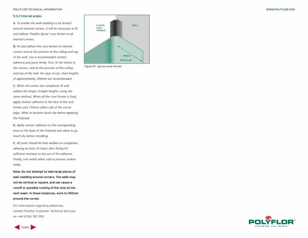
9.3.2 Internal angles
A. To enable the wall-cladding to be formed
around internal corners, it will be necessary to fit
and adhere ‘Polyflor Ejecta’ cove former to all
internal corners.
B. Fit and adhere the cove former to internal
corners and at the junction of the ceiling and top
of the wall. Use a recommended contact
adhesive,and press firmly. First, fit the mitres in
the corners, and at the junction of the ceiling
and top of the wall. For ease of use, short lengths
of approximately 300mm are recommended.
C. When all corners are completed, fit and
adhere the longer straight lengths, using the
same method. When all the cove former is fixed,
apply contact adhesive to the face of the cove
former and 150mm either side of the corner
edge. Allow to become touch dry before applying
the Polyclad.
D. Apply contact adhesive to the corresponding
area on the back of the Polyclad and allow to go
touch dry before installing.
E. All joints should be heat welded on completion,
allowing at least 24 hours after fitting for
sufficient moisture to dry out of the adhesive.
Finally, trim welds when cold to prevent sunken
welds.
Note: Do not attempt to take large pieces of
wall-cladding around corners. The walls may
not be vertical or square, and can cause a
runoff or possible rucking of the vinyl at the
next seam. In these instances, work to 150mm
around the corner.
For information regarding adhesives,
contact Polyflor Customer Technical Services
on +44 (0)161 767 1912.
index
WWW.POLYFLOR.COMPOLYFLOR TECHNICAL INFORMATION
Figure 27 Ejecta cover former
WALL
POLYCLAD
EJECTACOVEFORMER
150mm
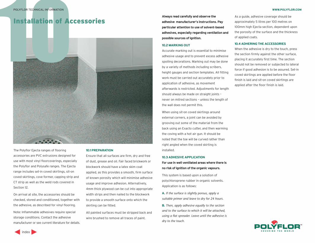
10
The Polyflor Ejecta ranges of flooring
accessories are PVC extrusions designed for
use with most vinyl floorcoverings, especially
the Polyflor and Polysafe ranges. The Ejecta
range includes set-in coved skirtings, sit-on
coved skirtings, cove former, capping strip and
CT strip as well as the weld rods covered in
Section 12.
On arrival at site, the accessories should be
checked, stored and conditioned, together with
the adhesive, as described for vinyl flooring.
Note: Inflammable adhesives require special
storage conditions. Contact the adhesive
manufacturer or see current literature for details.
10.1 PREPARATION
Ensure that all surfaces are firm, dry and free
of dust, grease and oil. Fair faced brickwork or
blockwork should have a latex skim coat
applied, as this provides a smooth, firm surface
of known porosity which will minimise adhesive
usage and improve adhesion. Alternatively,
4mm thick plywood can be cut into appropriate
width strips and then nailed to the blockwork
to provide a smooth surface onto which the
skirting can be fitted.
All painted surfaces must be stripped back and
wire brushed to remove all traces of paint.
Always read carefully and observe the
adhesive manufacturer’s instructions. Pay
particular attention to use of solvent-based
adhesives, especially regarding ventilation and
possible sources of ignition.
10.2 MARKING OUT
Accurate marking out is essential to minimise
adhesive usage and to prevent excess adhesive
spoiling decorations. Marking out may be done
by a variety of methods including scribers,
height gauges and section templates. All fitting
work must be carried out accurately prior to
application of adhesive, as movement
afterwards is restricted. Adjustments for length
should always be made on straight joints –
never on mitred sections – unless the length of
the wall does not permit this.
When using sit-on coved skirtings around
external corners, a joint can be avoided by
grooving out some of the material from the
back using an Exacto cutter, and then warming
the coving with a hot air gun. It should be
noted that the toe will be curved rather than
right angled when the coved skirting is
installed.
10.3 ADHESIVE APPLICATION
For use in well ventilated areas where there is
no risk of ignition of the organic vapours.
This system is based upon a solution of
polychloroprene rubber in organic solvents.
Application is as follows:
A. If the surface is slightly porous, apply a
suitable primer and leave to dry for 24 hours.
B. Then, apply adhesive equally to the section
and to the surface to which it will be attached,
using a flat spreader. Leave until the adhesive is
dry to the touch.
As a guide, adhesive coverage should be
approximately 5 litres per 100 metres on
100mm high Ejecta section, dependent upon
the porosity of the surface and the thickness
of applied coats.
10.4 ADHERING THE ACCESSORIES
When the adhesive is dry to the touch, press
the section firmly against the other surface,
placing it accurately first time. The section
should not be removed or subjected to lateral
force if good adhesion is to be assured. Set-in
coved skirtings are applied before the floor
finish is laid and sit-on coved skirtings are
applied after the floor finish is laid.
index
WWW.POLYFLOR.COMPOLYFLOR TECHNICAL INFORMATION
Installation of Accessories
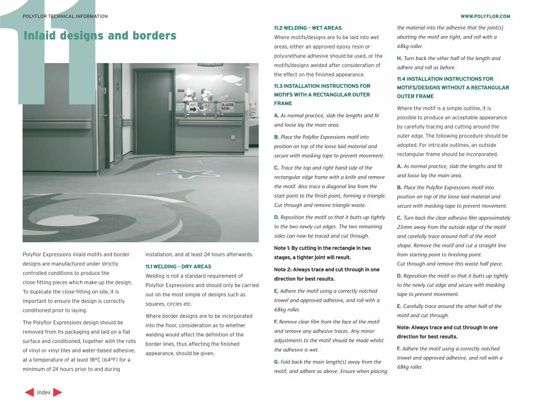
Polyflor Expressions inlaid motifs and border
designs are manufactured under strictly
controlled conditions to produce the
close-fitting pieces which make up the design.
To duplicate the close-fitting on site, it is
important to ensure the design is correctly
conditioned prior to laying.
The Polyflor Expressions design should be
removed from its packaging and laid on a flat
surface and conditioned, together with the rolls
of vinyl or vinyl tiles and water-based adhesive,
at a temperature of at least 18°C (64°F) for a
minimum of 24 hours prior to and during
installation, and at least 24 hours afterwards.
11.1 WELDING – DRY AREAS
Welding is not a standard requirement of
Polyflor Expressions and should only be carried
out on the most simple of designs such as
squares, circles etc.
Where border designs are to be incorporated
into the floor, consideration as to whether
welding would affect the definition of the
border lines, thus affecting the finished
appearance, should be given.
1111.2 WELDING – WET AREAS
Where motifs/designs are to be laid into wet
areas, either an approved epoxy resin or
polyurethane adhesive should be used, or the
motifs/designs welded after consideration of
the effect on the finished appearance.
11.3 INSTALLATION INSTRUCTIONS FOR
MOTIFS WITH A RECTANGULAR OUTER
FRAME
A. As normal practice, slab the lengths and fit
and loose lay the main area.
B. Place the Polyflor Expressions motif into
position on top of the loose laid material and
secure with masking tape to prevent movement.
C. Trace the top and right hand side of the
rectangular edge frame with a knife and remove
the motif. Also trace a diagonal line from the
start point to the finish point, forming a triangle.
Cut through and remove triangle waste.
D. Reposition the motif so that it butts up tightly
to the two newly cut edges. The two remaining
sides can now be traced and cut through.
Note 1: By cutting in the rectangle in two
stages, a tighter joint will result.
Note 2: Always trace and cut through in one
direction for best results.
E. Adhere the motif using a correctly notched
trowel and approved adhesive, and roll with a
68kg roller.
F. Remove clear film from the face of the motif
and remove any adhesive traces. Any minor
adjustments to the motif should be made whilst
the adhesive is wet.
G. Fold back the main length(s) away from the
motif, and adhere as above. Ensure when placing
the material into the adhesive that the joint(s)
abutting the motif are tight, and roll with a
68kg roller.
H. Turn back the other half of the length and
adhere and roll as before.
11.4 INSTALLATION INSTRUCTIONS FOR
MOTIFS/DESIGNS WITHOUT A RECTANGULAR
OUTER FRAME
Where the motif is a simple outline, it is
possible to produce an acceptable appearance
by carefully tracing and cutting around the
outer edge. The following procedure should be
adopted. For intricate outlines, an outside
rectangular frame should be incorporated.
A. As normal practice, slab the lengths and fit
and loose lay the main area.
B. Place the Polyflor Expressions motif into
position on top of the loose laid material and
secure with masking tape to prevent movement.
C. Turn back the clear adhesive film approximately
25mm away from the outside edge of the motif
and carefully trace around half of the motif
shape. Remove the motif and cut a straight line
from starting point to finishing point.
Cut through and remove this waste half piece.
D. Reposition the motif so that it butts up tightly
to the newly cut edge and secure with masking
tape to prevent movement.
E. Carefully trace around the other half of the
motif and cut through.
Note: Always trace and cut through in one
direction for best results.
F. Adhere the motif using a correctly notched
trowel and approved adhesive, and roll with a
68kg roller.
index
WWW.POLYFLOR.COMPOLYFLOR TECHNICAL INFORMATION
Inlaid designs and borders
G. Remove clear film from the face of the motif
and remove any adhesive traces. Any minor
adjustments to the motif should be made whilst
the adhesive is still wet.
H. Fold back the main length(s) away from the
motif and adhere as above. Ensure when placing
the material into the adhesive that the joint(s)
abutting the motif are tight, and roll with a
68kg roller.
I. Turn back the other half of length and adhere
and roll as before.
Polyflor Expressions designs are maintained in
the same manner as the surrounding Polyflor
vinyl floorcovering. (Full details are given in
Section 19 of this manual).
11.5 INSTALLATION OF BORDERS
A. Measure and mark the subfloor, using chalk
lines to correspond with the required border
positions. Measure the main lengths required to
fit inside the border, allowing approximately
25mm overlap.
B. Lay out the material so that it is overlapping
the inner edge of the border chalk line.
C. Snap the chalk line over the top of the material
to correspond with the inner border lines.
D. Using a knife and straight edge, carefully trace
along the chalk lines and cut and remove the
25mm surplus. The material can now be folded
back and adhered, taking care to retain a
straight line around all outside edges. The area
must then be rolled.
E. The border pieces now require positioning up
to the newly-cut straight edges, and adhering.
The clear film on the face of the border design
should then be removed and any minor
adjustments to the border made whilst the
adhesive is wet. The border can then be rolled.
F. The outer margin can now be fitted and
adhered to the finished border.
index
WWW.POLYFLOR.COMPOLYFLOR TECHNICAL INFORMATION

12
Polyflor strongly recommends that all Polyflor
vinyl sheet and 608mm vinyl tile floorings are
welded, this includes the internal and external
joints when the vinyl sheet is site cove formed.
Most specifications make welding mandatory,
since it prevents ingress of dirt and bacteria
into seams and provides a floor surface which is
impermeable to water. However, welding will
only aid maintenance of high standards of
hygiene if it is executed correctly.
The guidelines provided below should be
followed carefully, since short cuts taken in
welding create potential problems with seam
failures.
12.1 HEAT WELDING
Heat welding of vinyl floorcoverings has been
used successfully for many years and employs
the technique of heating both the vinyl flooring
and the vinyl welding rod to a sufficient
temperature to melt and fuse them together.
The procedure is the same for both sheet and
tile installation with the exception that the
edge of the tiles do not require cutting in prior
to grooving.
12.2 CORRECT TOOLS
Having the correct tools in good condition is a
prerequisite of good heat welding. The tools
required are dependent upon preferred methods
but as a guide the following are suggested:
2 metre rigid straight edge
Straight and hook bladed knives
Grooving tools – manual and powered
Welding equipment – manual and automatic
Spatula • Trimming guide
Exacto trimming tools • Under scriber
Feed roller • Chalk line
Wire brush • Seam cutters
See also Section 14.
12.3 CUTTING IN THE SEAMS
Factory edges should never be butted together
but should be overlapped and cut by one of the
following methods:
12.3.1 Using Seam Cutters
Set the first cutter to the thickness of vinyl
sheet. Using the factory edge as a guide, trim
off 6mm along the length. Where it is not
possible to use the seam cutter against the
wall, or in other areas of restricted access, use
a straight edge and straight bladed knife held
squarely to the floor.
Set the second cutter to the thickness of vinyl
sheet. Using the edge previously cut on the
top sheet as a guide, cut through the bottom
sheet. Remove the scrap piece of material.
12.3.2 Using an Under Scriber
Prior to overlapping the vinyl sheet, trim off
the factory edge on the bottom sheet. This is
best done by striking a chalk line, then – using
a utility knife and straight edge – cut through
and remove the scrap piece.
Overlap the top sheet and then trace the
bottom edge onto the top sheet with correctly
set under scribers. To highlight the scribed line,
rub some chalk dust into the surface. Trim the
top sheet to the scribed line.
12.4 GROOVING THE SEAMS
Strike a chalk line along the overlap. Using a
utility knife and straight edge, double cut the
joint through both layers of material, ensuring
that the knife blade is held squarely to the floor.
Prior to welding, some of the material must be
removed from the seam, creating a groove that
will accept the vinyl welding rod. Two shapes of
groove can be cut:
1. A “U” shape – which leaves a semi-circular
groove in the vinyl. This should extend into the
vinyl for 2/3 of its thickness, up to a maximum
of 2mm.
2. A “V” shape – which leaves a 60º triangular
groove in the vinyl. This should extend into the
vinyl for 7/8 of its thickness.
Note: The ‘V’ shaped groove has proven
particularly suitable for embossed versions of
Polysafe vinyl sheet floorcovering.
The groove on Acoustic and Sports flooring
should only be cut in the vinyl wear layer. It
should never be cut through to the PVC foam
backing.
12.4.1 Manual Grooving
Place the centre of the grooving tool over the
centre of the seam. Bring up the straight edge
to touch the side of the cutter, and align the
straight edge, maintaining an even distance
from the seam (Figure 28).
Pulling the tool towards you, groove to the
required depth. Move the straight edge as
required and repeat until the whole seam is
grooved. Sweep well to remove any dust and
trimmings from the groove.
index
WWW.POLYFLOR.COMPOLYFLOR TECHNICAL INFORMATION
Welding vinyl flooring
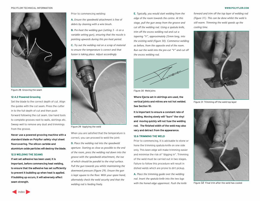
12.4.2 Powered Grooving
Set the blade to the correct depth of cut. Align
the guides with the cut seam. Press the cutter
in to the full depth of cut and then push
forward following the cut seam. Use hand tools
to complete grooves next to walls, skirtings etc.
Sweep well to remove any dust and trimmings
from the groove.
Never use a powered grooving machine with a
standard blade on Polyflor safety vinyl sheet
floorcovering. The silicon carbide and
aluminium oxide particles will destroy the blade.
12.5 WELDING THE SEAMS
If wet set adhesive has been used, it is
important, before commencing heat welding,
to ensure that the adhesive has set sufficiently
to prevent it bubbling up when heat is applied.
If bubbling up occurs, it will adversely affect
seam strength.
Prior to commencing welding:
A. Ensure the speedweld attachment is free of
debris by cleaning with a wire brush.
B. Pre-heat the welding gun (setting 3 - 6 on a
variable setting gun), ensuring that the nozzle is
pointing upwards during this pre-heat period.
C. Try out the welding rod on a scrap of material
to ensure the temperature is correct and that
fusion is taking place. Adjust accordingly.
When you are satisfied that the temperature is
correct, you can proceed to weld the joint:
D. Place the welding rod into the speedweld
aperture. Starting as close as possible to the end
of the room, press the welding rod down into the
groove with the speedweld attachment, the toe
of which should be parallel to the vinyl surface.
Pull the gun towards you whilst maintaining the
downward pressure (Figure 29). Ensure the gun
is kept square to the floor. With your spare hand,
alternately check the weld security and that the
welding rod is feeding freely.
E. Typically, you would start welding from the
edge of the room towards the centre. At this
stage, pull the gun away from the groove and
cut off the welding rod. Using a spatula knife,
trim off the excess welding rod and cut a
tapering “V”, approximately 25mm long, into
the existing weld (Figure 30). Commence welding
as before, from the opposite end of the room.
Run out the weld into the pre-cut “V” and cut off
the excess welding rod.
Where Ejecta set-in skirtings are used, the
vertical joints and mitres are not hot welded.
See Section 10.
It is important to ensure a constant rate of
welding. Moving slowly will “burn” the vinyl
and moving quickly will not fuse the welding
rod. The finished width of the weld may also
vary and detract from the appearance.
12.6 TRIMMING THE WELD
Prior to commencing, it is advisable to stone or
hone the trimming spatula knife on one side
only. This keen edge will make trimming easier
and minimise the risk of “digging in”. Trimming
of the weld must be carried out in two stages.
Failure to follow this procedure will result in
dished welds which are prone to dirt pickup.
A. Place the trimming guide over the welding
rod. Insert the spatula knife into the two lugs
with the honed edge uppermost. Push the knife
forward and trim off the top layer of welding rod
(Figure 31). This can be done whilst the weld is
still warm. Trimming the weld speeds up the
cooling time.
index
WWW.POLYFLOR.COMPOLYFLOR TECHNICAL INFORMATION
Figure 28 Grooving the seam
Figure 29 Applying the weld
Figure 30 Weld joins
Figure 31 Trimming off the weld top layer
Figure 32 Final trim after the weld has cooled
B. When the remaining weld has cooled to room
temperature, the excess weld should be trimmed.
The spatula knife, again honed edge uppermost,
is used without the trimming guide. Keep as
shallow an angle as possible between blade and
floor to avoid the risk of “digging in” (Figure 32).
Note: Polyflor foam backed vinyl sheet flooring
is liable to compression and sometimes, even
after the final trim, the weld is proud of the
floor. In this case, use an Exacto cutter with a
large circular blade to scrape away any high
spots.
12.7 GLAZING THE WELD
Should a glazed finish be required this can be
achieved with the speedweld attachment
removed but still on the same heat setting,
play the gun nozzle over the trimmed weld.
Repeat over the whole length of the weld,
keeping the gun moving constantly to prevent
burning.
index
WWW.POLYFLOR.COMPOLYFLOR TECHNICAL INFORMATION
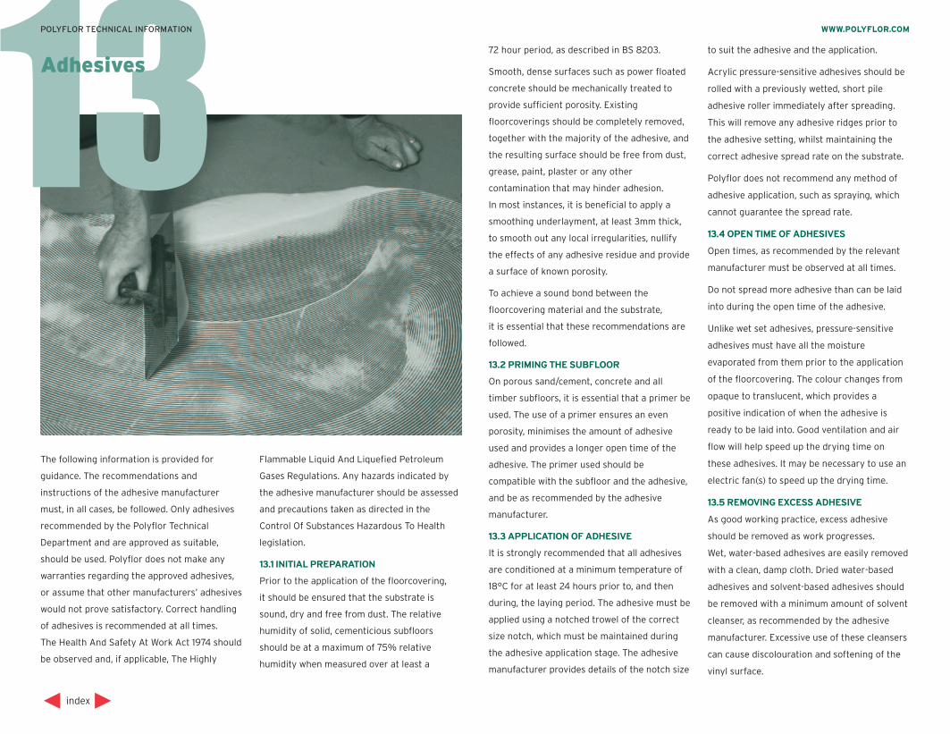
13
The following information is provided for
guidance. The recommendations and
instructions of the adhesive manufacturer
must, in all cases, be followed. Only adhesives
recommended by the Polyflor Technical
Department and are approved as suitable,
should be used. Polyflor does not make any
warranties regarding the approved adhesives,
or assume that other manufacturers’ adhesives
would not prove satisfactory. Correct handling
of adhesives is recommended at all times.
The Health And Safety At Work Act 1974 should
be observed and, if applicable, The Highly
Flammable Liquid And Liquefied Petroleum
Gases Regulations. Any hazards indicated by
the adhesive manufacturer should be assessed
and precautions taken as directed in the
Control Of Substances Hazardous To Health
legislation.
13 .1 INITIAL PREPARATION
Prior to the application of the floorcovering,
it should be ensured that the substrate is
sound, dry and free from dust. The relative
humidity of solid, cementicious subfloors
should be at a maximum of 75% relative
humidity when measured over at least a
72 hour period, as described in BS 8203.
Smooth, dense surfaces such as power floated
concrete should be mechanically treated to
provide sufficient porosity. Existing
floorcoverings should be completely removed,
together with the majority of the adhesive, and
the resulting surface should be free from dust,
grease, paint, plaster or any other
contamination that may hinder adhesion.
In most instances, it is beneficial to apply a
smoothing underlayment, at least 3mm thick,
to smooth out any local irregularities, nullify
the effects of any adhesive residue and provide
a surface of known porosity.
To achieve a sound bond between the
floorcovering material and the substrate,
it is essential that these recommendations are
followed.
13.2 PRIMING THE SUBFLOOR
On porous sand/cement, concrete and all
timber subfloors, it is essential that a primer be
used. The use of a primer ensures an even
porosity, minimises the amount of adhesive
used and provides a longer open time of the
adhesive. The primer used should be
compatible with the subfloor and the adhesive,
and be as recommended by the adhesive
manufacturer.
13.3 APPLICATION OF ADHESIVE
It is strongly recommended that all adhesives
are conditioned at a minimum temperature of
18°C for at least 24 hours prior to, and then
during, the laying period. The adhesive must be
applied using a notched trowel of the correct
size notch, which must be maintained during
the adhesive application stage. The adhesive
manufacturer provides details of the notch size
to suit the adhesive and the application.
Acrylic pressure-sensitive adhesives should be
rolled with a previously wetted, short pile
adhesive roller immediately after spreading.
This will remove any adhesive ridges prior to
the adhesive setting, whilst maintaining the
correct adhesive spread rate on the substrate.
Polyflor does not recommend any method of
adhesive application, such as spraying, which
cannot guarantee the spread rate.
13.4 OPEN TIME OF ADHESIVES
Open times, as recommended by the relevant
manufacturer must be observed at all times.
Do not spread more adhesive than can be laid
into during the open time of the adhesive.
Unlike wet set adhesives, pressure-sensitive
adhesives must have all the moisture
evaporated from them prior to the application
of the floorcovering. The colour changes from
opaque to translucent, which provides a
positive indication of when the adhesive is
ready to be laid into. Good ventilation and air
flow will help speed up the drying time on
these adhesives. It may be necessary to use an
electric fan(s) to speed up the drying time.
13.5 REMOVING EXCESS ADHESIVE
As good working practice, excess adhesive
should be removed as work progresses.
Wet, water-based adhesives are easily removed
with a clean, damp cloth. Dried water-based
adhesives and solvent-based adhesives should
be removed with a minimum amount of solvent
cleanser, as recommended by the adhesive
manufacturer. Excessive use of these cleansers
can cause discolouration and softening of the
vinyl surface.
index
WWW.POLYFLOR.COMPOLYFLOR TECHNICAL INFORMATION
Adhesives
13.6 ROLLING THE FLOOR
Once the floorcovering has been laid, the
material should be rolled immediately with a
68kg articulated floor roller, working initially in
the widthways direction, if it is sheet material.
This rolling ensures good contact between the
substrate, adhesive and floorcovering, expels
any trapped air, and flattens the adhesive
ridges to prevent shadow through once the
floor becomes trafficked.
The floorcovering should be rolled again, one
to four hours later, to ensure the contact
between the materials is maintained.
13.7 PROTECTION FROM RADIATED HEAT
SOURCES
The Polysafe range of floorcoverings is often
used in situations where excessive heat causes
problems with the floorcovering and the
adhesive. It is impractical to give specific
details, as equipment such as ovens and kilns
vary in design and height above the flooring
material.
Where the conditions may cause a problem, we
would recommend the use of metal oven trays
that deflect the heat away from the floor, and
an adhesive suitable for these conditions, such
as an epoxy or polyurethane. If you are unsure,
we recommend that you discuss the
application with our Customer Technical
Services team.
13.8 APPROVED ADHESIVES
There are many different types of adhesive
available in the marketplace, and the suitability
for use with the range of Polyflor products
depends upon a number of factors.
The formulation of the adhesive, the
formulation of the floorcovering, the site
conditions and the in-use conditions all affect
the selection.
The Technical Department of Polyflor checks
the compatibility between the adhesive and the
floorcoverings. The current list of approved
adhesives for the full range of Polyflor
products is available, on request, from the
Customer Technical Services Department of
Polyflor, their distributors or approved agents.
index
WWW.POLYFLOR.COMPOLYFLOR TECHNICAL INFORMATION

14Tools and Equipment
14.3 HEAT WELDING
Grooving tools Hot welding gun
Spatula trimming knife Speedweld nozzle
Trimming guide Oilstone
14.4 PREPARATION
Long handled broom Hand brush
Dust pan Hygrometer
Screeding trowel Grind stone
Electric drill (slow speed) and rotary paddle
14.5 MISCELLANEOUS
Claw hammer Screwdriver
Hacksaw Handsaw
Electric drill Various twist drills
Mastic gun
14.6 SAFETY EQUIPMENT
Knee pads Safety goggles
Face mask Circuit breaker
14.7 OPTIONAL EQUIPMENT
The following equipment is not essential but
will greatly assist the floor layer, especially on
larger installations.
Powered stripper Transformer
Automatic welding machine
Powered groover Floor grinder
Vacuum cleaner Extension lead
14.8 SPECIALIST TOOLS
In addition to the basic tools, there is a range
of specialist tools which are designed for
specific tasks such as coving, feature work,
walls and repairs. Some of the more common
tools are listed, together with a brief descrip-
tion of their usage.
index
WWW.POLYFLOR.COMPOLYFLOR TECHNICAL INFORMATION
As in all trades, a skilled floor layer should have
at his disposal a basic set of tools that should
be clean and in good condition.
The specific choice of tools is dependent upon
the individual floor layer’s preferences, the size
of installation and the amount of preparation
required.
The following tools should be considered as
part of the basic kit for the operations
indicated.
14.1 MARKING OUT & FITTING
Rule Chalk line and chalk
Bar or long scriber Recess scriber
Dividers or short scribers Straight edge
Pencil and compass Pencils
Various trimming knives
14.2 INSTALLATION
Adhesive trowels Triangular file
68kg articulated roller Hand roller
Powered groover
Tape Measure
Hot air welding gun
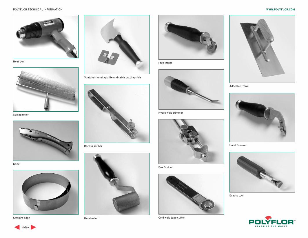
index
WWW.POLYFLOR.COMPOLYFLOR TECHNICAL INFORMATION
Straight edge
Knife
Heat gun
Spiked roller
Recess scriber
Hand roller
Feed Roller
Box Scriber
Hand Groover
Cold weld tape cutter
Exacto tool
Hydro weld trimmer
Adhesive trowel
Spatula trimming knife and cable cutting slide
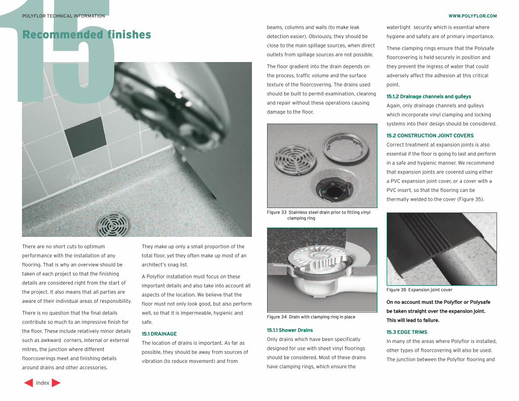
15
There are no short cuts to optimum
performance with the installation of any
flooring. That is why an overview should be
taken of each project so that the finishing
details are considered right from the start of
the project. It also means that all parties are
aware of their individual areas of responsibility.
There is no question that the final details
contribute so much to an impressive finish for
the floor. These include relatively minor details
such as awkward corners, internal or external
mitres, the junction where different
floorcoverings meet and finishing details
around drains and other accessories.
They make up only a small proportion of the
total floor, yet they often make up most of an
architect’s snag list.
A Polyflor installation must focus on these
important details and also take into account all
aspects of the location. We believe that the
floor must not only look good, but also perform
well, so that it is impermeable, hygienic and
safe.
15.1 DRAINAGE
The location of drains is important. As far as
possible, they should be away from sources of
vibration (to reduce movement) and from
beams, columns and walls (to make leak
detection easier). Obviously, they should be
close to the main spillage sources, when direct
outlets from spillage sources are not possible.
The floor gradient into the drain depends on
the process, traffic volume and the surface
texture of the floorcovering. The drains used
should be built to permit examination, cleaning
and repair without these operations causing
damage to the floor.
15.1.1 Shower Drains
Only drains which have been specifically
designed for use with sheet vinyl floorings
should be considered. Most of these drains
have clamping rings, which ensure the
watertight security which is essential where
hygiene and safety are of primary importance.
These clamping rings ensure that the Polysafe
floorcovering is held securely in position and
they prevent the ingress of water that could
adversely affect the adhesion at this critical
point.
15.1.2 Drainage channels and gulleys
Again, only drainage channels and gulleys
which incorporate vinyl clamping and locking
systems into their design should be considered.
15.2 CONSTRUCTION JOINT COVERS
Correct treatment at expansion joints is also
essential if the floor is going to last and perform
in a safe and hygienic manner. We recommend
that expansion joints are covered using either
a PVC expansion joint cover, or a cover with a
PVC insert, so that the flooring can be
thermally welded to the cover (Figure 35).
On no account must the Polyflor or Polysafe
be taken straight over the expansion joint.
This will lead to failure.
15.3 EDGE TRIMS
In many of the areas where Polyflor is installed,
other types of floorcovering will also be used.
The junction between the Polyflor flooring and
index
WWW.POLYFLOR.COMPOLYFLOR TECHNICAL INFORMATION
Recommended finishes
Figure 33 Stainless steel drain prior to fitting vinyl clamping ring
Figure 34 Drain with clamping ring in place
Figure 35 Expansion joint cover
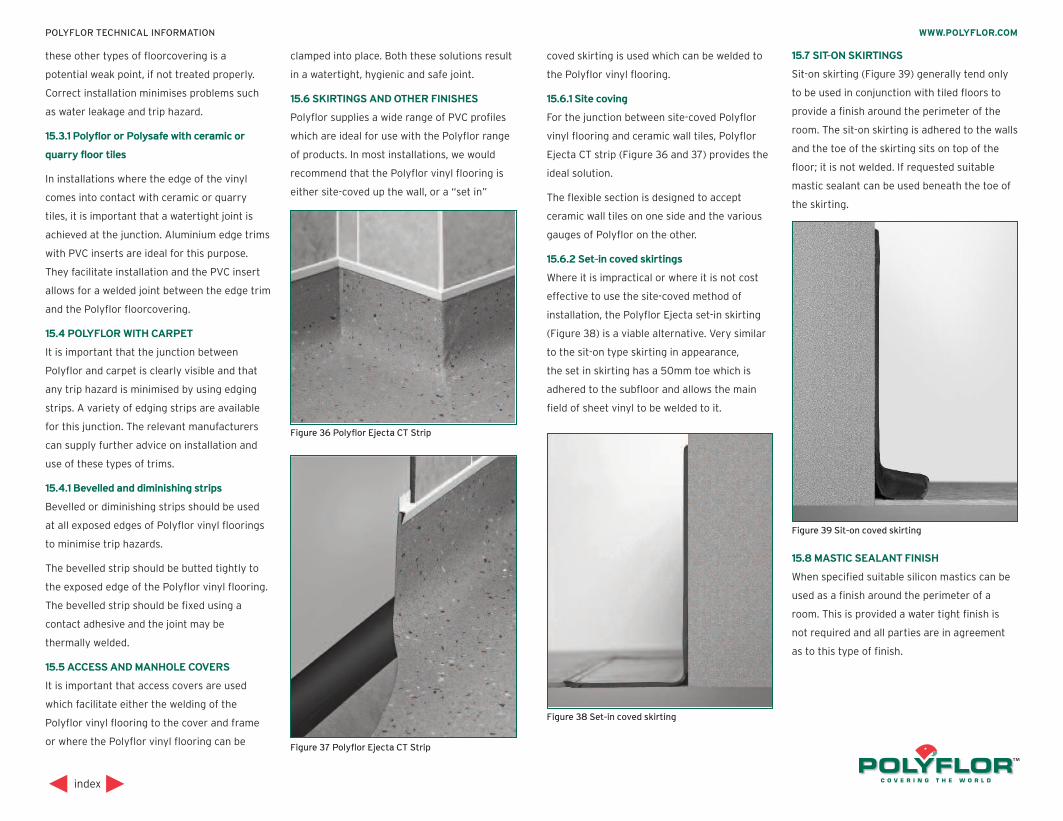
these other types of floorcovering is a
potential weak point, if not treated properly.
Correct installation minimises problems such
as water leakage and trip hazard.
15.3.1 Polyflor or Polysafe with ceramic or
quarry floor tiles
In installations where the edge of the vinyl
comes into contact with ceramic or quarry
tiles, it is important that a watertight joint is
achieved at the junction. Aluminium edge trims
with PVC inserts are ideal for this purpose.
They facilitate installation and the PVC insert
allows for a welded joint between the edge trim
and the Polyflor floorcovering.
15.4 POLYFLOR WITH CARPET
It is important that the junction between
Polyflor and carpet is clearly visible and that
any trip hazard is minimised by using edging
strips. A variety of edging strips are available
for this junction. The relevant manufacturers
can supply further advice on installation and
use of these types of trims.
15.4.1 Bevelled and diminishing strips
Bevelled or diminishing strips should be used
at all exposed edges of Polyflor vinyl floorings
to minimise trip hazards.
The bevelled strip should be butted tightly to
the exposed edge of the Polyflor vinyl flooring.
The bevelled strip should be fixed using a
contact adhesive and the joint may be
thermally welded.
15.5 ACCESS AND MANHOLE COVERS
It is important that access covers are used
which facilitate either the welding of the
Polyflor vinyl flooring to the cover and frame
or where the Polyflor vinyl flooring can be
clamped into place. Both these solutions result
in a watertight, hygienic and safe joint.
15.6 SKIRTINGS AND OTHER FINISHES
Polyflor supplies a wide range of PVC profiles
which are ideal for use with the Polyflor range
of products. In most installations, we would
recommend that the Polyflor vinyl flooring is
either site-coved up the wall, or a “set in”
coved skirting is used which can be welded to
the Polyflor vinyl flooring.
15.6.1 Site coving
For the junction between site-coved Polyflor
vinyl flooring and ceramic wall tiles, Polyflor
Ejecta CT strip (Figure 36 and 37) provides the
ideal solution.
The flexible section is designed to accept
ceramic wall tiles on one side and the various
gauges of Polyflor on the other.
15.6.2 Set-in coved skirtings
Where it is impractical or where it is not cost
effective to use the site-coved method of
installation, the Polyflor Ejecta set-in skirting
(Figure 38) is a viable alternative. Very similar
to the sit-on type skirting in appearance,
the set in skirting has a 50mm toe which is
adhered to the subfloor and allows the main
field of sheet vinyl to be welded to it.
15.7 SIT-ON SKIRTINGS
Sit-on skirting (Figure 39) generally tend only
to be used in conjunction with tiled floors to
provide a finish around the perimeter of the
room. The sit-on skirting is adhered to the walls
and the toe of the skirting sits on top of the
floor; it is not welded. If requested suitable
mastic sealant can be used beneath the toe of
the skirting.
15.8 MASTIC SEALANT FINISH
When specified suitable silicon mastics can be
used as a finish around the perimeter of a
room. This is provided a water tight finish is
not required and all parties are in agreement
as to this type of finish.
index
WWW.POLYFLOR.COMPOLYFLOR TECHNICAL INFORMATION
Figure 36 Polyflor Ejecta CT Strip
Figure 37 Polyflor Ejecta CT Strip
Figure 38 Set-in coved skirting
Figure 39 Sit-on coved skirting
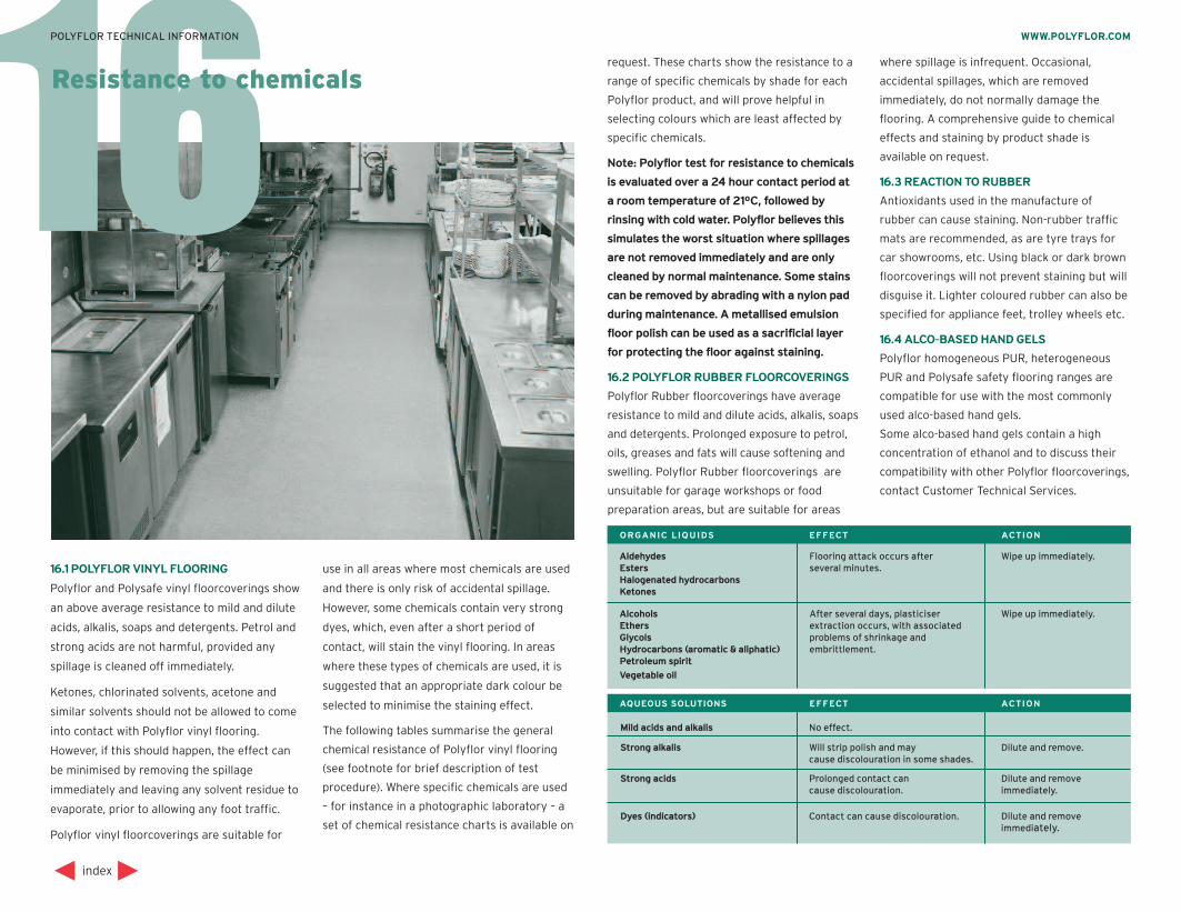
Aldehydes Flooring attack occurs after Wipe up immediately. Esters several minutes. Halogenated hydrocarbons Ketones
Alcohols After several days, plasticiser Wipe up immediately. Ethers extraction occurs, with associated Glycols problems of shrinkage and Hydrocarbons (aromatic & aliphatic) embrittlement. Petroleum spirit Vegetable oil
ORGAN IC L IQU IDS EFFECT ACT ION
Mild acids and alkalis No effect.
Strong alkalis Will strip polish and may Dilute and remove. cause discolouration in some shades.
Strong acids Prolonged contact can Dilute and remove cause discolouration. immediately. Dyes (indicators) Contact can cause discolouration. Dilute and remove immediately.
AQUEOUS SOLUTIONS EFFECT ACT ION
16
16.1 POLYFLOR VINYL FLOORING
Polyflor and Polysafe vinyl floorcoverings show
an above average resistance to mild and dilute
acids, alkalis, soaps and detergents. Petrol and
strong acids are not harmful, provided any
spillage is cleaned off immediately.
Ketones, chlorinated solvents, acetone and
similar solvents should not be allowed to come
into contact with Polyflor vinyl flooring.
However, if this should happen, the effect can
be minimised by removing the spillage
immediately and leaving any solvent residue to
evaporate, prior to allowing any foot traffic.
Polyflor vinyl floorcoverings are suitable for
use in all areas where most chemicals are used
and there is only risk of accidental spillage.
However, some chemicals contain very strong
dyes, which, even after a short period of
contact, will stain the vinyl flooring. In areas
where these types of chemicals are used, it is
suggested that an appropriate dark colour be
selected to minimise the staining effect.
The following tables summarise the general
chemical resistance of Polyflor vinyl flooring
(see footnote for brief description of test
procedure). Where specific chemicals are used
– for instance in a photographic laboratory – a
set of chemical resistance charts is available on
request. These charts show the resistance to a
range of specific chemicals by shade for each
Polyflor product, and will prove helpful in
selecting colours which are least affected by
specific chemicals.
Note: Polyflor test for resistance to chemicals
is evaluated over a 24 hour contact period at
a room temperature of 21ºC, followed by
rinsing with cold water. Polyflor believes this
simulates the worst situation where spillages
are not removed immediately and are only
cleaned by normal maintenance. Some stains
can be removed by abrading with a nylon pad
during maintenance. A metallised emulsion
floor polish can be used as a sacrificial layer
for protecting the floor against staining.
16.2 POLYFLOR RUBBER FLOORCOVERINGS
Polyflor Rubber floorcoverings have average
resistance to mild and dilute acids, alkalis, soaps
and detergents. Prolonged exposure to petrol,
oils, greases and fats will cause softening and
swelling. Polyflor Rubber floorcoverings are
unsuitable for garage workshops or food
preparation areas, but are suitable for areas
where spillage is infrequent. Occasional,
accidental spillages, which are removed
immediately, do not normally damage the
flooring. A comprehensive guide to chemical
effects and staining by product shade is
available on request.
16.3 REACTION TO RUBBER
Antioxidants used in the manufacture of
rubber can cause staining. Non-rubber traffic
mats are recommended, as are tyre trays for
car showrooms, etc. Using black or dark brown
floorcoverings will not prevent staining but will
disguise it. Lighter coloured rubber can also be
specified for appliance feet, trolley wheels etc.
16.4 ALCO-BASED HAND GELS
Polyflor homogeneous PUR, heterogeneous
PUR and Polysafe safety flooring ranges are
compatible for use with the most commonly
used alco-based hand gels.
Some alco-based hand gels contain a high
concentration of ethanol and to discuss their
compatibility with other Polyflor floorcoverings,
contact Customer Technical Services.
index
WWW.POLYFLOR.COMPOLYFLOR TECHNICAL INFORMATION
Resistance to chemicals
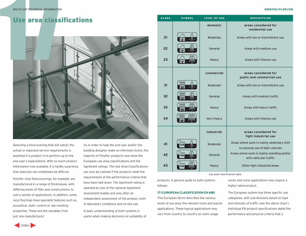
17Use area classifications C L A S S S Y M B O L L E V E L O F U S E D E S C R I P T I O N
Use area classification table
domestic areas considered for residential use
21 A Moderate Areas with low or intermittent use
22 B General Areas with medium use
23 D Heavy Areas with intense use
commercial areas considered for public and commercial use
31 E Moderate Areas with low or intermittent use
32 F General Areas with medium traffic
33 G Heavy Areas with heavy traffic
34 H Very Heavy Areas with intense use
industrial areas considered for light industrial use
41 I Moderate Areas where work is mainly sedentary with occasional use of light vehicles
42 J General Areas where work is mainly standing and/or with vehicular traffic
43 K Heavy Other light industrial areas
Selecting a floorcovering that will satisfy the
actual or expected service requirements is
essential if a product is to perform up to the
end user’s expectations. With so much product
information now available, it is hardly surprising
that selection can sometimes be difficult.
Polyflor vinyl floorcoverings, for example, are
manufactured in a range of thicknesses, with
differing levels of filler and constructions, to
suit a variety of applications. In addition, some
vinyl floorings have specialist features such as
acoustical, static control or slip-resisting
properties. These are the variables from
just one manufacturer!
So in order to help the end user and/or the
building designer make an informed choice, the
majority of Polyflor products now show the
European use area classifications and the
Agrément ratings. The Use Area Classifications
can only be claimed if the products meet the
requirements of the performance criteria that
have been laid down. The Agrément rating is
awarded by one of the national Agrément
assessment bodies and only after an
independent assessment of the product, both
in laboratory conditions and on-site use.
A basic understanding of both systems is
useful when making decisions on suitability of
products. A general guide to both systems
follows:
17.1 EUROPEAN CLASSIFICATION EN 685
This European Norm describes the various
levels of use area, the relevant icons and typical
applications. These typical applications may
vary from country to country as room usage
varies and some applications may require a
higher rated product.
The European system has three specific use
categories, with sub-divisions based on type
and intensity of traffic (see the above chart.)
Individual EN product specifications detail the
performance and physical criteria that a
index
WWW.POLYFLOR.COMPOLYFLOR TECHNICAL INFORMATION
product must meet to achieve the classification
– and products can meet the criteria of all
three groups. When a higher classification
number is claimed, the product will meet all the
requirements of the lower classes in that
group.
The individual EN product specifications allow
for products of different filler levels and
abrasion resistance and define minimum overall
and wear layer thickness for each classification.
Homogeneous products, being 100% wear
layer, are classified using the minimum wear
layer thickness and the overall thickness.
Compared to an heterogeneous product of the
same classification which would give a typical
life expectancy of 10 years, a ‘P’ abrasion group
homogenous product has twice as much useful
life and as such the life expectancy would be
20 years in a class 34/43 use area.
17.2 AGRÉMENT SYSTEM
The Agrément system, which originated in
France, has been in use for many years.
The ratings were based on four key physical
properties. The results which the product
achieved against a test criteria in each
category gave it the overall rating. (The higher
the number, the better the performance.)
The overall performance was then quoted as a
UPEC rating and this system is still recognised
today in France. In 1987, the scheme for
floorcoverings was revised, but still retained
the basic concepts that made the scheme so
useful. The revision, carried out in conjunction
with the European floorcovering manufacturers,
made the overall scheme simpler. As all vinyl
floorcoverings achieved a C2 rating when
tested, it was felt unnecessary to include this
and the new system concentrated on the U, P
and E ratings.
The new scheme was termed the GWS system,
with G being the general classification ranging
from 1 to 5 and being a combination of the
previous U and P ratings. W indicates that the
product can tolerate wet cleaning but not
standing water. WS indicates the product can
tolerate standing water by having the joints
welded. The W and S replace the previous
E rating.
A comparison of both ratings is as follows:
G1 is equivalent to U2 P2
G2 is equivalent to U2+P2
G3 is equivalent to U3 P2
G4 is equivalent to U3 P3
G5 is equivalent to U4 P3
No W rating is equivalent to E1
W rating is equivalent to E2
WS rating is equivalent to E3
The Agrément bodies produce a comprehensive
listing of typical use areas, which are too
numerous to list here, together with the
product rating required. Contact Polyflor or
index
WWW.POLYFLOR.COMPOLYFLOR TECHNICAL INFORMATION
their overseas agents for the address of the
local national body that can provide this
information.
17.3 EUROPEAN NORMS
European Norms – or “EN”s – are aimed at
harmonising industry standards throughout
the European Union and EFTA countries, and
have now replaced the old British Standards
relating to floorcoverings.
The standards are:
EN 649 covering homogeneous and
heterogeneous vinyls, and replacing
BS 3261A.
EN 650 covering jute or polyester backed
vinyls.
EN 651 covering homogeneous and
heterogeneous vinyls on PVC foam,
and replacing BS 5085.
EN 652 covering vinyl flooring with a cork
based backing.
EN 653 covering expanded PVC flooring such
as cushion vinyls.
EN 654 covering semi-flexible PVC tiles,
and replacing BS 3260.
EN 655 for PVC tiles with a base of
agglomerated cork and a PVC
wear layer.
The relevant ENs which apply to Polyflor vinyl
floorcoverings are 649, 651 and 654.
Under EN 649, products are given an abrasion
group rating. There are two test methods
accepted for abrasion which have an
established correlation; EN 660 Parts 1 and 2.
Either can be used to establish the abrasion
category.
The ratings are expressed as T,P, M and F.
These groups were chosen with reference to
the already well established Agrément system,
and relate to the idea of a notional 10-year life
expectancy in a given use area. The initials
come from the French: Transparent, Pas or Peu
chargé, Moyen chargé and Fortement chargé,
and basically relate to the amount of filler
(chargé) used in a formulation.
EN 649 defines the performance criteria which
products must meet in order to claim Use Area
Classification under EN 685, as discussed in
Section 17.1.
In addition to the vinyl specification,
specifications for rubber flooring have now
been published. They are:
EN 1817 Homogeneous and heterogeneous
rubber flooring.
EN 1816 Homogeneous and heterogeneous
rubber flooring with foam backing.
EN 12199Homogeneous and heterogeneous
relief rubber flooring.
Wear (Unsure) U 1-4
Penetration (Poinçonnements) P 1-4
Water resistance (Eau) E 1-3
Chemical resistance (Chimique) C 1-3
PROPERTY ( FRENCH TERM) SYMBOL RANGE
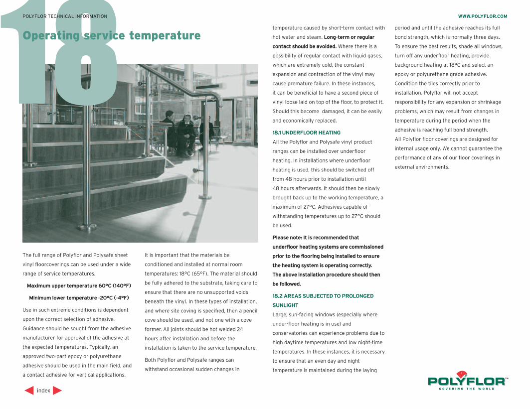
18
The full range of Polyflor and Polysafe sheet
vinyl floorcoverings can be used under a wide
range of service temperatures.
Maximum upper temperature 60°C (140°F)
Minimum lower temperature -20°C (-4°F)
Use in such extreme conditions is dependent
upon the correct selection of adhesive.
Guidance should be sought from the adhesive
manufacturer for approval of the adhesive at
the expected temperatures. Typically, an
approved two-part epoxy or polyurethane
adhesive should be used in the main field, and
a contact adhesive for vertical applications.
It is important that the materials be
conditioned and installed at normal room
temperatures: 18°C (65°F). The material should
be fully adhered to the substrate, taking care to
ensure that there are no unsupported voids
beneath the vinyl. In these types of installation,
and where site coving is specifıed, then a pencil
cove should be used, and not one with a cove
former. All joints should be hot welded 24
hours after installation and before the
installation is taken to the service temperature.
Both Polyflor and Polysafe ranges can
withstand occasional sudden changes in
temperature caused by short-term contact with
hot water and steam. Long-term or regular
contact should be avoided. Where there is a
possibility of regular contact with liquid gases,
which are extremely cold, the constant
expansion and contraction of the vinyl may
cause premature failure. In these instances,
it can be beneficial to have a second piece of
vinyl loose laid on top of the floor, to protect it.
Should this become damaged, it can be easily
and economically replaced.
18.1 UNDERFLOOR HEATING
All the Polyflor and Polysafe vinyl product
ranges can be installed over underfloor
heating. In installations where underfloor
heating is used, this should be switched off
from 48 hours prior to installation until
48 hours afterwards. It should then be slowly
brought back up to the working temperature, a
maximum of 27°C. Adhesives capable of
withstanding temperatures up to 27°C should
be used.
Please note: It is recommended that
underfloor heating systems are commissioned
prior to the flooring being installed to ensure
the heating system is operating correctly.
The above installation procedure should then
be followed.
18.2 AREAS SUBJECTED TO PROLONGED
SUNLIGHT
Large, sun-facing windows (especially where
under-floor heating is in use) and
conservatories can experience problems due to
high daytime temperatures and low night-time
temperatures. In these instances, it is necessary
to ensure that an even day and night
temperature is maintained during the laying
period and until the adhesive reaches its full
bond strength, which is normally three days.
To ensure the best results, shade all windows,
turn off any underfloor heating, provide
background heating at 18°C and select an
epoxy or polyurethane grade adhesive.
Condition the tiles correctly prior to
installation. Polyflor will not accept
responsibility for any expansion or shrinkage
problems, which may result from changes in
temperature during the period when the
adhesive is reaching full bond strength.
All Polyflor floor coverings are designed for
internal usage only. We cannot guarantee the
performance of any of our floor coverings in
external environments.
index
WWW.POLYFLOR.COMPOLYFLOR TECHNICAL INFORMATION
Operating service temperature
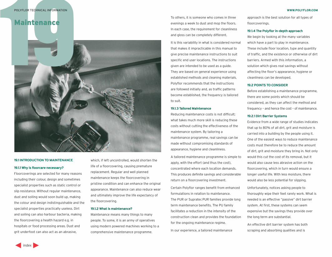
19
19.1 INTRODUCTION TO MAINTENANCE
19.1.1 Why is floorcare necessary?
Floorcoverings are selected for many reasons
including their colour, design and sometimes
specialist properties such as static control or
slip resistance. Without regular maintenance,
dust and soiling would soon build up, making
the colour and design indistinguishable and the
specialist properties practically useless. Dirt
and soiling can also harbour bacteria, making
the floorcovering a health hazard e.g. in
hospitals or food processing areas. Dust and
grit underfoot can also act as an abrasive,
which, if left uncontrolled, would shorten the
life of a floorcovering, causing premature
replacement. Regular and well planned
maintenance keeps the floorcovering in
pristine condition and can enhance the original
appearance. Maintenance can also reduce wear
and ultimately improve the life expectancy of
the floorcovering.
19.1.2 What is maintenance?
Maintenance means many things to many
people. To some, it is an army of operatives
using modern powered machines working to a
comprehensive maintenance programme.
index
WWW.POLYFLOR.COMPOLYFLOR TECHNICAL INFORMATION
MaintenanceTo others, it is someone who comes in three
evenings a week to dust and mop the floors.
In each case, the requirement for cleanliness
and gloss can be completely different.
It is this variability in what is considered normal
that makes it impracticable in this manual to
give precise maintenance instructions to suit
specific end user locations. The instructions
given are intended to be used as a guide.
They are based on general experience using
established methods and cleaning materials.
Polyflor recommends that the instructions
are followed initially and, as traffic patterns
become established, the frequency is tailored
to suit.
19.1.3 Tailored Maintenance
Reducing maintenance costs is not difficult;
what takes much more skill is reducing these
costs without cutting the effectiveness of the
maintenance system. By tailoring a
maintenance programme, real savings can be
made without compromising standards of
appearance, hygiene and cleanliness.
A tailored maintenance programme is simple to
apply, with the effort (and thus the cost),
concentrated where each location demands.
This produces definite savings and considerable
return on a floorcovering investment.
Certain Polyflor ranges benefit from enhanced
formulations in relation to maintenance.
The PUR or SupratecPUR families provide long
term maintenance benefits. The PU family
facilitates a reduction in the intensity of the
construction clean and provides the foundation
for the ongoing maintenance regime.
In our experience, a tailored maintenance
approach is the best solution for all types of
floorcoverings.
19.1.4 The Polyflor in-depth approach
We begin by looking at the many variables
which have a part to play in maintenance.
These include floor location, type and quantity
of traffic, and the existence or otherwise of dirt
barriers. Armed with this information, a
solution which gives real savings without
affecting the floor’s appearance, hygiene or
cleanliness can be developed.
19.2 POINTS TO CONSIDER
Before establishing a maintenance programme,
there are some points which should be
considered, as they can affect the method and
frequency – and hence the cost – of maintenance.
19.2.1 Dirt Barrier Systems
Evidence from a wide range of studies indicates
that up to 80% of all dirt, grit and moisture is
carried into a building by the people using it.
One of the easiest ways to reduce maintenance
costs must therefore be to reduce the amount
of dirt, grit and moisture they bring in. Not only
would this cut the cost of its removal, but it
would also cause less abrasive action on the
floorcovering, which in turn would ensure a
longer useful life. With less moisture, there
would also be less potential for slipping.
Unfortunately, notices asking people to
thoroughly wipe their feet rarely work. What is
needed is an effective “passive” dirt barrier
system. At first, these systems can seem
expensive but the savings they provide over
the long term are substantial.
An effective dirt barrier system has both
scraping and absorbing qualities and is
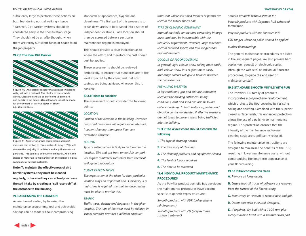
sufficiently large to perform these actions on
both feet during normal walking – hence
“passive”. Dirt barrier systems should be
considered early in the specification stage.
They should not be an afterthought, when
there are rarely sufficient funds or space to do
the job properly.
19.2.2 The Ideal Dirt Barrier
Note: To maintain the effectiveness of dirt
barrier systems, they must be cleaned
regularly, otherwise they can actually increase
the soil intake by creating a “soil reservoir” at
the entrance to the building.
19.3 ASSESSING THE LOCATION
As mentioned earlier, by tailoring the
maintenance programme, real and achievable
savings can be made without compromising
standards of appearance, hygiene and
cleanliness. The first part of this process is to
break down areas to be cleaned into a series of
independent locations. Each location should
then be assessed before a particular
maintenance regime is employed.
This should provide a clear indication as to
where the effort and therefore the cost should
best be applied.
These assessments should be reviewed
periodically, to ensure that standards are to the
level expected by the client and that cost
savings are being achieved wherever this is
possible.
19.3.1 Points to consider
The assessment should consider the following
points:
LOCATION
Position of the location in the building. Entrance
areas and receptions will require more intensive,
frequent cleaning than upper floor, low
circulation corridors.
SOILING
Type of soiling which is likely to be found in the
location. Dirt and grit from an outside car park
will require a different treatment from chemical
spillage in a laboratory.
CLIENT EXPECTATIONS
The expectation of the client for that particular
location plays an important part. Obviously, if a
high shine is required, the maintenance regime
must be able to provide this.
TRAFFIC
Traffic types, density and frequency in the given
location. The type of footwear used by children in
school corridors provides a different situation
from that where soft soled trainers or pumps are
used in the school sports hall.
TYPE OF CLEANING EQUIPMENT
Manual methods can be time consuming in large
areas and may be incompatible with the
frequency requirement. However, large machines
used in confined spaces can take longer than
manual methods.
COLOUR OF FLOORCOVERING
In general, light colours show soiling more easily,
dark colours show loss of gloss more easily.
Mid range colours will give a balance between
the two extremes.
PREVAILING WEATHER
In icy conditions, grit and salt are sometimes
used outside building entrances. In dry
conditions, dust and sand can also be found
outside buildings. In both instances, soiling and
abrasion can be accelerated if effective measures
are not taken to prevent them being trafficked
into the building.
19.3.2 The Assessment should establish the
following:
1. The type of cleaning needed
2. The frequency of cleaning
3. The cleaning products and equipment needed
4. The level of labour required
5. The time to be allocated
19.4 INDIVIDUAL PRODUCT MAINTENANCE
PROCEDURES
As the Polyflor product portfolio has developed,
the maintenance procedures have become
specific to generic types which are:
Smooth products with PUR (polyurethane
reinforcement)
Smooth products with PU (polyurethanesurface treatment)
Smooth products without PUR or PU
Polysafe products with Supratec PUR enhancedformulation
Polysafe products without Supratec PUR
ESD ranges where no polish should be applied
Rubber floorcoverings
The general maintenance procedures are listed
in the subsequent pages. We also provide hard
copies (on request) or electronic copies
(through the web site) of individual floorcare
procedures, to guide the end user or
maintenance staff.
19.5 STANDARD SMOOTH VINYLS WITH PUR
The Polyflor PUR family of products
incorporates a polyurethane reinforcement,
which protects the floorcovering by resisting
soiling and scuffing. Combined with the superior
closed surface finish, this enhanced protection
allows the use of a polish-free maintenance
regime. This protection ensures that the
intensity of the maintenance and overall
cleaning costs are significantly reduced.
The following maintenance instructions are
designed to maximise the benefits of the PUR,
resulting in lower maintenance costs, without
compromising the long-term appearance of
your floorcovering.
19.5.1 Initial construction clean
A. Remove all loose debris.
B. Ensure that all traces of adhesive are removed
from the surface of the floorcovering.
C. Mop sweep or vacuum to remove dust and grit.
D. Damp mop with a neutral detergent.
E. If required, dry buff with a 1000 rpm plus
rotary machine fitted with a suitable clean pad.
index
WWW.POLYFLOR.COMPOLYFLOR TECHNICAL INFORMATION
Figure 40 An exterior scraper mat at least two paceswide, set into a matwell. The choice of materials isvaried. Clearance should be sufficient to allow gritand debris to fall below. Also allowances must be made for the wearers of various types of shoese.g. stiletto heels.
Figure 41 An interior grade combination scraper/
moisture mat of two to three metres in length. This will
remove the majority of moisture and any fine abrasive
particles. This can also be set into a matwell. Again, the
choice of materials is wide and often the barrier will be a
composite of several materials.
19.5.2 Routine maintenance
The following recommendations are provided
as a guideline, and the frequency can be
changed to optimise the appearance.
DAILY
Mop sweep or vacuum to remove dust and loose
dirt. If required, spot mop to remove stubborn
marks, with a neutral cleanser.
WEEKLY
Assess the appearance of the floor.
Undertake the following as required:
Light scuffing – dry buff with a 1000 rpm plus
rotary machine fitted with a suitable clean pad.
or
Heavier scuffing – spray clean using a floor
maintainer and 1000 rpm plus rotary machine
fitted with a suitable clean pad.
19.5.3 Periodic Maintenance
A. Assess the appearance of the floor. If the floor
has dirt build–up, machine scrub with a scrubber
dryer (approx. 165 rpm) fitted with a suitable
clean pad, using a neutral or alkaline detergent,
as appropriate.
B. Rinse thoroughly and allow to dry.
C. Dry buff to restore finish.
19.5.4 Additional Information:
1. The maintenance regime requires the
installation of an effective barrier matting system.
2. Cleaners and detergents should be diluted as
per the manufacturers’ instructions.
3. Always follow the Health and Safety guidance
provided.
4. Fit protective feet to table and chair legs, to
prevent scratching.
5. These maintenance instructions are intended
for the PUR family of floorcoverings, which have
a polyurethane reinforcement.
For other Polyflor products, reference should be
made to the relevant section or to their specific
floorcare sheets.
6. In most instances, the above maintenance
regime will be sufficient to ensure your
floorcovering retains the optimum appearance.
However where there is no mechanical means of
maintaining the floor, an emulsion floor polish
should be applied. Details of the procedure to be
used can be found under the Standard Vinyl with
PU section.
7. Regular cleaning is more beneficial to the
floorcovering and more cost-effective than
occasional heavy cleaning.
19.6 STANDARD SMOOTH VINYL WITH PU
Polyflor smooth vinyl ‘PU’ floorcoverings
incorporate a polyurethane surface treatment,
which protects the floorcovering by resisting
soiling and scuffing. This protection facilitates
a reduction in the intensity of the construction
clean and provides the foundation for the
ongoing maintenance regime. This easier
cleanability offers maintenance cost savings
when compared with non-treated materials.
The following maintenance instructions are
designed to minimise the cost factor, without
compromising the long-term appearance of
your floorcovering.
19.6.1 Initial construction clean
A. Remove all loose debris.
B. Ensure that all traces of adhesive are removed
from the surface of the floorcovering.
C. Mop sweep or vacuum to remove dust and grit.
D. Damp mop with a neutral detergent.
E. If required, dry buff with a 1000 rpm plus
rotary machine fitted with a suitable clean pad.
19.6.2 Routine maintenance
The following recommendations are provided
as a guideline, and the frequencies can be
changed to optimise the appearance.
DAILY
Mop sweep or vacuum to remove dust and loose
dirt. If required, spot clean to remove stubborn
marks with a neutral cleanser. If required, dry
buff to restore finish.
WEEKLY/MONTHLY
Assess the appearance of the floor. If required,
scrub with a scrubber dryer fitted with suitable
pads, and using neutral cleanser (pH 7 to 9).
If required, dry buff to restore finish.
19.6.3 Application of a floor dressing
The Polyurethane surface treatment will
provide initial protection for the floorcovering.
However, an application of a metallised polish
may be required eventually to provide extra
protection. The level and intensity of traffic and
soiling will determine how soon the polish will
have to be applied. For polish free maintenance,
see the Polyflor PUR range of products.
For polish application, please follow details of
the procedure below.
A. Using an applicator and tray, or Kentucky mop
with wringer and bucket, the first coat should be
applied thinly and evenly across the floor, to
within 200mm of the skirtings. It should then be
left to dry. This normally takes approximately
thirty minutes, depending on the ambient
conditions and the thickness of the coating.
B. When the first coat is dry, a second coat
should be applied at right angles to the direction
of the first. Subsequent coats should be applied
at right angles, and the final coat should be
applied right up to the skirting.
Two to three thin coats are usually sufficient to
provide excellent resistance to abrasion,
scuffing and removal of black heel marking.
However, be guided by your own periodic
assessments for the particular location.
In order to minimise costs, subsequent polish
applications may be applied only to traffic
paths.
Periodically – generally every six months –
assess the appearance of the floor. If there is
an unacceptable build-up of polish, this should
be stripped and reapplied, as per the
instructions above.
19.6.4 Additional Information:
1. The maintenance regime requires the installation
of an effective barrier matting system.
2. Cleaners and detergents should be diluted as
per the manufacturers’ instructions.
3. These maintenance instructions are intended
for the Polyflor ‘PU’ family, which incorporates a
polyurethane surface treatment. For other
Polyflor products, reference should be made to
the relevant section or to their specific floorcare
sheets.
4. For further guidance, contact Polyflor
Customer Technical Services.
5. Always follow the Health and Safety guidance
provided.
6. Regular cleaning is more beneficial to the
floorcovering and more cost-effective than
occasional heavy cleaning.
index
WWW.POLYFLOR.COMPOLYFLOR TECHNICAL INFORMATION
19.7 STANDARD SMOOTH VINYL RANGES
WITHOUT PU OR PUR
19.7.1 Initial construction clean
A. Sweep, mop sweep or dry vacuum the floor, to
remove dust, grit and debris.
B. For light soiling, damp mop the floor with a
neutral cleanser diluted to the manufacturer’s
instructions.
or
For heavy soiling, apply a solution of alkaline
cleanser, diluted to the manufacturer’s
instructions, to the floor and leave for sufficient
time to react with the soiling. Using a 165 to
350 rpm rotary machine fitted with a scrubbing
pad, machine scrub the floor and then pick up
the slurry with a wet vacuum. Rinse the floor
thoroughly with clean warm water, pick up with
a wet vacuum and leave to dry thoroughly.
19.7.2 Application of a floor dressing
A. Ensure that there is a good key between the
floor dressing and the surface of the flooring,
scrubbing the floor if required.
B. Either of the following methods can be used:
EMULSION POLISH.
Apply two or three thin coats of emulsion polish
in accordance with the manufacturer’s
instructions, with either a proprietary polish
applicator or Kentucky mop wrung out to prevent
over-application of polish. The polish should be
applied up to 150mm from the edges of the
room, and subsequent coats should be applied at
90º to the previous one. The final coat should be
applied right up to the edges of the room.
or
SPRAY CLEAN/POLISH.
The floor maintainer should be used undiluted for
the first 2–3 applications, to enable a protective
film to be developed as quickly as possible and,
thereafter, in accordance with the manufacturer’s
instructions.
Note: To provide adequate protection in high
traffic areas, it can be more effective to apply
an emulsion polish, rather than spray clean/
polish. Where a high shine finish is undesirable,
a matt finish polish should be used.
19.7.3 Routine maintenance
The frequency of each of the operations is
dependent upon the type and intensity of traffic.
A. Sweep, mop sweep or dry vacuum the floor, to
remove dust and loose dirt.
B. Spot mop frequently. Stubborn black marks
can be removed by using the centre disc of a
scrubbing pad and a small amount of undiluted
alkaline cleanser. Place the disc under the sole of
the shoe and rub – this gives greater pressure.
Rinse the area well with clean warm water and
leave to dry.
C. Depending upon the end user requirement
and the equipment available, one of the
following methods should be used:
Using floor maintainer, diluted to the
manufacturer’s instructions, mop the floor and
leave to dry. If a shine is required, the floor
should be buffed with a 500 to 2000 rpm rotary
machine fitted with a suitable pad.
or
Using floor maintainer, diluted to the
manufacturer’s instructions, spray a fine mist
onto the floor. Using a 165 to 500 rpm rotary
machine and suitable spray cleaning pad, buff
the floor to the desired shine. The dirt is picked
up in the pad, which should be thoroughly
cleaned after use. Failure to do so will result in a
shiny, dirty floor.
or
Using a neutral or germicidal cleanser, diluted to
the manufacturer’s instructions, mop the floor
and allow to dry completely. Using a 500 to
2000 rpm rotary machine, buff the floor to the
desired level of shine.
Note: When high speed burnishing, it is
important that the machine is kept constantly
moving. This avoids excessive heat build-up on
the floor. As an additional precaution,
we advise that a spray of clean water is used,
to help lubricate the pad.
19.7.4 Removal of a floor dressing
An unsightly build-up of polish should be
avoided. The polish should be removed
regularly - the interval between application and
removal depends on the wear conditions and
the number of polish layers (normally six
months in heavy traffic areas.) Follow the
manufacturer’s instructions.
19.7.5 Additional Information
1. Always follow the Health and Safety guidance
provided.
2. Regular cleaning is more beneficial to the
floorcovering and more cost-effective than
occasional heavy cleaning.
19.8 POLYSAFE RANGES WITH PUR
The following maintenance instructions are
designed to minimise the cost factor, while
ensuring that your floorcovering retains the
optimum appearance and performance.
The exclusive Polysafe PUR system reduces
the intensity of cleaning and the use of
chemicals, which helps minimise the effect on
the environment, without compromising such
key elements as hygiene and underfoot safety.
19.8.1 Construction clean
Polysafe PUR is designed to resist soiling,
which ensures that – even after transportation,
installation and the period prior to handover –
the intensity of construction clean can be
significantly reduced. This will have a beneficial
impact on the initial costs.
A. Remove all loose debris.
B. Remove surface dust and grit by sweeping or
vacuuming.
C. Apply a solution of neutral cleanser (or alkaline
cleanser, dependent upon the level of soiling),
diluted to the manufacturer’s instructions, with a
spray over the section to be cleaned. Leave for
sufficient time to react with the soiling.
D. Pick up the solution with a clean microfibre
mop, using a continuous side-to-side motion.
When the mop head becomes loaded, it will start
streaking the floor. At this point, the dirty mop
head should be removed and placed into a
laundry bag and a clean mop head fitted.
The cycle should then be repeated until the
whole floor is completed.
E. The dirty mop heads should then be laundered
in preparation for reuse.
Note: If the floor has been heavily scuffed,
it may be necessary to use a Doodle bug or
similar tool fitted with a suitable pad to
remove the scuff marks
19.8.2 Daily maintenance
A. Remove surface dust and grit by sweeping or
vacuuming.
B. Apply a solution of neutral cleanser (or alkaline
cleanser, dependent upon the level of grease or
index
WWW.POLYFLOR.COMPOLYFLOR TECHNICAL INFORMATION
oily contaminates), diluted to the manufacturer’s
instructions, with a spray over the section to be
cleaned. Leave for sufficient time to react with
the soiling.
C. Pick up the solution with a clean microfibre
mop, using a continuous side-to-side motion.
When the mop head becomes loaded, it will start
streaking the floor. At this point, the dirty mop
head should be removed and placed into a
laundry bag and a clean mop head fitted.
The cycle should then be repeated until the
whole floor is completed.
D. The dirty mop heads should then be laundered,
in preparation for reuse.
E. Where detergent residue remains on the floor
surface, the area should be rinsed completely
with clean, warm water, picked up with a wet
vacuum and left to dry thoroughly.
F. In areas subject to heavy soiling, machine
scrubbing should be undertaken on a periodic
basis, after neutral or alkaline cleanser has been
applied to the floor, diluted to the manufacturers’
instructions.
19.8.3 Additional Information
1. This maintenance procedure has been designed
to optimise the benefits of the Polysafe PUR
system – the latest in proven cleaning technology.
The maximum benefits are derived from this
system by carrying out this quick and simple
procedure on a daily basis, and by using clean
equipment each time, to maximise dirt pick-up
and eliminate streaking.
2. A floor dressing or maintainer containing
polish should not be applied to Polysafe ranges
with PUR, as this may impair the slip resistance.
If in doubt, consult our Customer Technical
Services staff.
3. Always follow the Health and Safety guidance
provided.
4. Regular cleaning is more beneficial to the
floorcovering and more cost-effective than
occasional heavy cleaning.
5. Cleaners and detergents should be diluted as
per the manufacturers’ instructions.
For recommended products, see the Polyflor
Approved Maintenance Products sheet located
within the Technical section of www.polyflor.com
6. Polysafe safety flooring ranges are compatible
for use with the most commonly used alco-based
hand gels and are suitable for steam cleaning on
a periodic basis.
All the above methods of maintenance can be
applied to Polysafe PUR and Polysafe
Supratec PUR products - the 3rd generation
maintenance enhancement available on
flagship Polysafe ranges.
19.9 POLYSAFE RANGES WITHOUT PUR
19.9.1 Construction clean
A. Sweep, mop sweep or dry vacuum the floor to
remove dust, grit and debris.
B. Apply a solution of alkaline cleanser, diluted to
the manufacturer’s instructions, to the floor and
leave for sufficient time to react with the soiling.
C. Using a 165 rpm rotary machine fitted with a
rotary scrubbing brush or, if necessary,
a scrubbing pad, machine scrub the floor and
then pick up the slurry with a wet vacuum.
D. Rinse the floor thoroughly with clean warm
water, pick up with a wet vacuum and leave to
dry thoroughly.
For small areas, where there is no suitable
scrubbing machine available, a deck scrubber
should be used in conjunction with a wet
vacuum or mop and bucket system.
Dilution rates above the manufacturer’s
minimum recommendations may be necessary
for very heavy soiling.
For Polysafe Hydro, the scrubbing pad should
be replaced with a rotary scrubbing brush or a
cylindrical type scrubbing machine.
19.9.2 Ongoing maintenance
For ongoing maintenance, the frequency of
each of the operations is dependent upon the
type and intensity of traffic as well as the
appearance expectations and should be
adjusted to suit.
19.9.3 Standard surface finish
A. Sweep, mop sweep or dry vacuum the floor, to
remove dust and loose dirt.
B. Spot mop regularly. Stubborn black marks can
be removed by using the centre disc of a scrubbing
pad and a small amount of undiluted alkaline
cleanser. Place the disc under the sole of the shoe
and rub – this gives greater pressure. Rinse the
area well with clean warm water and leave to dry.
C. Apply a solution of neutral or alkaline cleanser,
diluted to the manufacturer’s instructions, to the
floor and leave for sufficient time to react with
the soiling. Using a 165 rpm rotary machine fitted
with a rotary scrubbing brush or, if necessary, a
scrubbing pad, machine scrub the floor and then
pick up the slurry with a wet vacuum. Rinse
thoroughly with clean, warm water, pick up with
a wet vacuum and leave to dry thoroughly.
19.9.4 Polysafe Hydro with embossed surface
finish
A. Sweep, mop sweep or dry vacuum to remove
dust and loose dirt.
B. Spot scrub regularly with a deck scrubber.
C. Apply a solution of neutral or alkaline cleanser,
diluted to the manufacturer’s instructions, to the
floor and leave for sufficient time to react with
the soiling. Using a 165 rpm rotary machine
fitted with a bristle brush, cylindrical machine or
deck scrubber, scrub the floor and pick up the
slurry with a wet vacuum. Rinse thoroughly with
clean, warm water, pick up with a wet vacuum
and allow to dry thoroughly.
19.9.5 Additional Information
1. A floor dressing should not be applied to
Polysafe floorcoverings, as this may impair the
slip resistance. If in doubt, consult our Customer
Technical Services staff.
2. Always follow the Health and Safety guidance
provided.
3. Regular cleaning is more beneficial to the
floorcovering and more cost-effective than
occasional heavy cleaning.
4. Cleaners and detergents should be diluted as
per the manufacturers’ instructions.
For recommended products, see the Polyflor
Approved Maintenance Products sheet located
within the Technical section of www.polyflor.com
5. Polysafe safety flooring ranges are compatible
for use with the most commonly used alco-based
hand gels and are suitable for steam cleaning on
a periodic basis.
19.10 THE ESD FAMILY
The ESD family of vinyl floorcoverings are
designed to prevent damage to processes,
equipment or people by conducting static
charges away at a rate that prevents damage.
In order to ensure the ESD features work
effectively, it is important that the instructions
below are followed. Failure to do so could
render the ESD system ineffective.
index
WWW.POLYFLOR.COMPOLYFLOR TECHNICAL INFORMATION
19.10.1 Construction clean
A. Sweep, mop sweep or dry vacuum the floor, to
remove dust, grit and debris.
B. For light soiling, damp mop the floor with a
neutral cleanser, diluted to the manufacturer’s
instructions.
or
For heavy soiling, apply a solution of alkaline
cleanser, diluted to the manufacturer’s
instructions, to the floor and leave for sufficient
time to react with the soiling. Using a 165 to
350 rpm rotary machine fitted with a scrubbing
pad, machine scrub the floor and then pick up
the slurry with a wet vacuum. Rinse the floor
thoroughly with clean warm water, pick up with
a wet vacuum and leave to dry thoroughly.
19.10.2 Application of a Floor Dressing
Normal, commercially available polishes should
not be applied to Polyflor ESD products, as
they will inhibit the conductive properties.
Polishes described as ’antistatic‘ are classified
by a different standard from that of the
floorcovering, and should be treated as a
standard polish in static control terms.
Consequently, they should not be applied.
Conductive polishes which are approved by
Polyflor can be applied in strict accordance
with the manufacturer’s instructions. Prior to
application of a floor dressing, ensure that the
floor is thoroughly scrubbed. This will ensure
that there is a good key between the dressing
and the surface of the flooring. Always discuss
with our Technical Services staff before
applying a conductive polish.
19.10.3 Regular maintenance
The frequency of each of the operations is
dependent upon the type and intensity of traffic.
A. Sweep, mop sweep or dry vacuum, to remove
dust and loose dirt.
B. Spot mop frequently. Stubborn black marks
can be removed by using the centre disc of a
scrubbing pad and a small amount of undiluted
alkaline cleanser. Place the disc under the sole of
the shoe and rub – this gives greater pressure.
Rinse the area well with clean warm water and
allow to dry.
C. Depending upon the end user requirement
and the equipment available, one of the
following methods should be used:
Using an alkaline or germicidal cleanser, diluted
to the manufacturer’s instructions, spray a fine
mist onto the floor. Using a 165 to 500 rpm
rotary machine and suitable spray cleaning pad,
buff the floor to the desired shine. The dirt is
picked up in the pad, which should be thoroughly
cleaned after use. Failure to do so will result in a
shiny, dirty floor.
or
Using an alkaline or germicidal cleanser, diluted
to the manufacturer’s instructions, mop the floor
and allow to dry completely. Using a 500 to
2000 rpm rotary machine, buff the floor to the
desired level of shine.
NOTE : When high speed burnishing, it is
important that the machine is kept constantly
moving. This avoids excessive heat build-up on
the floor. As an additional precaution, we
advise that a spray of clean water is used to
help lubricate the pad.
19.10.4 Additional Information
1. Always ensure mops and pads are kept
especially for the static control areas, to prevent
a possible transfer of polish.
2. Always follow the Health and Safety guidance
provided.
3. Regular cleaning is more beneficial to the
floorcovering and more cost-effective than
occasional heavy cleaning.
19.11 RUBBER FLOORCOVERINGS
19.11.1 Construction clean
After installation, wait 48 hours before
proceeding with the construction/intensive
clean.
A. Sweep or dry vacuum the floor to remove dust,
grit and debris.
B. Apply a solution of alkaline cleanser, diluted as
per the manufacturer’s instructions, to the floor
and leave for at least 5 minutes (or longer if
manufacturer recommends) to react before
proceeding.
C. Using a 150/175 rpm rotary machine fitted
with fibre or nylon brushes, machine scrub the
floor and then pick up the slurry with a mop or
wet vacuum. The floor should then be rinsed with
clean water and allowed to dry.
19.11.2 Application of a floor dressing
A. Prior to the application of a floor dressing,
ensure that the floor is completely stripped, clean
and free from any contaminants. This will ensure
that there is a good key between the dressing
and the surface of the floor.
B. Apply two or three thin coats of emulsion
polish, in accordance with the manufacturer’s
instructions, with either a proprietary polish
applicator or Kentucky mop wrung out to prevent
over-application of polish. The polish should be
applied up to 150mm from the edges of the
room, and subsequent coats should be applied at
90° to the previous one. The final coat should be
applied right up to the edges of the room.
19.11.3 Routine maintenance
For ongoing maintenance, the frequency of
each of the operations should be adjusted to
suit the appearance expectations and the type
and intensity of traffic.
A. Sweep or dry vacuum daily, to remove dust
and loose dirt.
B. Spot mop frequently. Rinse the area with clean
warm water and allow to dry.
C. As required (normally at least once per week)
mop the floor using a floor maintainer, diluted as
per the manufacturer’s instructions, and leave to
dry. If a shine is required, the floor should be
buffed with a low-speed machine, typically
150/500 rpm, fitted with suitable fibre or nylon
brushes.
Regular buffing of the floorcovering will
enhance its appearance.
19.11.4 Removal of a floor dressing
An unsightly build-up of polish should be
avoided. The polish should be removed
regularly; the interval between application and
removal depends on the wear conditions and
the number of polish layers. (Normally, six
months in heavy traffic areas.)
A. Apply a solution of emulsion polish stripper,
diluted to the manufacturer’s instructions, to the
floor and leave for approximately 15 minutes.
B. Machine scrub with a 150/175 rpm machine
fitted with a scrubbing brush, and then remove
slurry with a wet vacuum. Thoroughly rinse the
floor with clean warm water, pick up with a wet
vacuum and allow to dry completely. The cycle of
polish application and routine maintenance
should then be repeated.
index
WWW.POLYFLOR.COMPOLYFLOR TECHNICAL INFORMATION
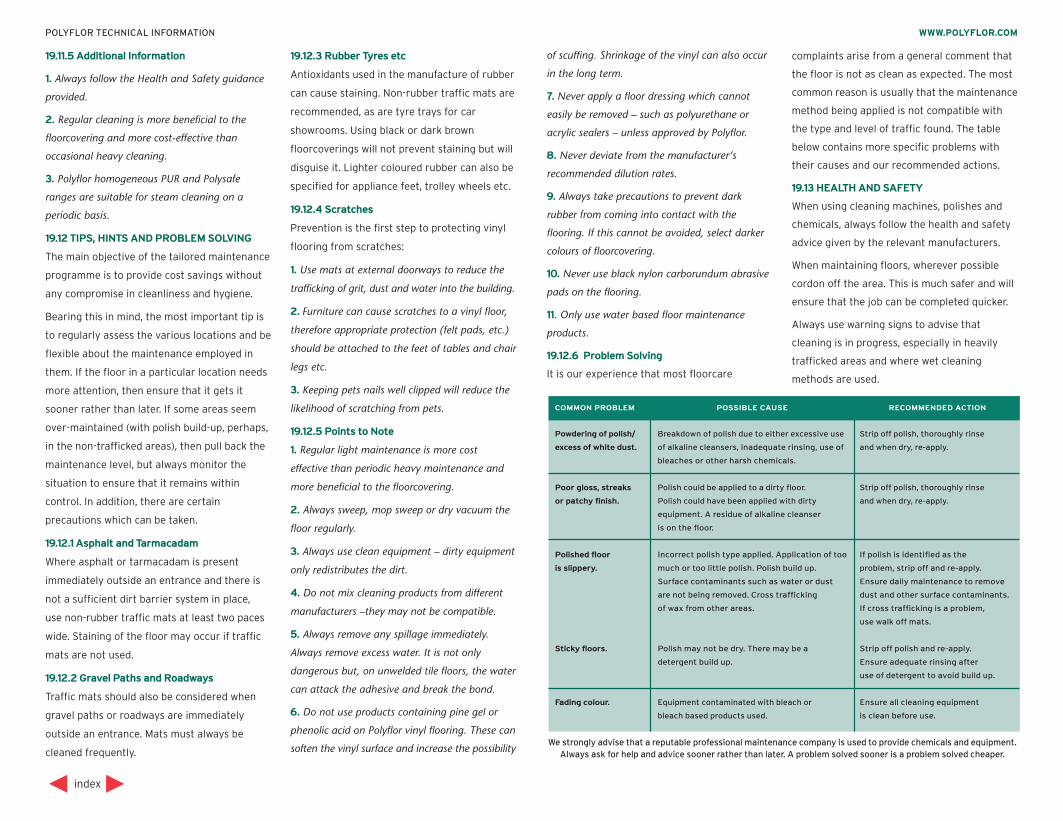
19.11.5 Additional Information
1. Always follow the Health and Safety guidance
provided.
2. Regular cleaning is more beneficial to the
floorcovering and more cost-effective than
occasional heavy cleaning.
3. Polyflor homogeneous PUR and Polysafe
ranges are suitable for steam cleaning on a
periodic basis.
19.12 TIPS, HINTS AND PROBLEM SOLVING
The main objective of the tailored maintenance
programme is to provide cost savings without
any compromise in cleanliness and hygiene.
Bearing this in mind, the most important tip is
to regularly assess the various locations and be
flexible about the maintenance employed in
them. If the floor in a particular location needs
more attention, then ensure that it gets it
sooner rather than later. If some areas seem
over-maintained (with polish build-up, perhaps,
in the non-trafficked areas), then pull back the
maintenance level, but always monitor the
situation to ensure that it remains within
control. In addition, there are certain
precautions which can be taken.
19.12.1 Asphalt and Tarmacadam
Where asphalt or tarmacadam is present
immediately outside an entrance and there is
not a sufficient dirt barrier system in place,
use non-rubber traffic mats at least two paces
wide. Staining of the floor may occur if traffic
mats are not used.
19.12.2 Gravel Paths and Roadways
Traffic mats should also be considered when
gravel paths or roadways are immediately
outside an entrance. Mats must always be
cleaned frequently.
19.12.3 Rubber Tyres etc
Antioxidants used in the manufacture of rubber
can cause staining. Non-rubber traffic mats are
recommended, as are tyre trays for car
showrooms. Using black or dark brown
floorcoverings will not prevent staining but will
disguise it. Lighter coloured rubber can also be
specified for appliance feet, trolley wheels etc.
19.12.4 Scratches
Prevention is the first step to protecting vinyl
flooring from scratches:
1. Use mats at external doorways to reduce the
trafficking of grit, dust and water into the building.
2. Furniture can cause scratches to a vinyl floor,
therefore appropriate protection (felt pads, etc.)
should be attached to the feet of tables and chair
legs etc.
3. Keeping pets nails well clipped will reduce the
likelihood of scratching from pets.
19.12.5 Points to Note
1. Regular light maintenance is more cost
effective than periodic heavy maintenance and
more beneficial to the floorcovering.
2. Always sweep, mop sweep or dry vacuum the
floor regularly.
3. Always use clean equipment – dirty equipment
only redistributes the dirt.
4. Do not mix cleaning products from different
manufacturers –they may not be compatible.
5. Always remove any spillage immediately.
Always remove excess water. It is not only
dangerous but, on unwelded tile floors, the water
can attack the adhesive and break the bond.
6. Do not use products containing pine gel or
phenolic acid on Polyflor vinyl flooring. These can
soften the vinyl surface and increase the possibility
of scuffing. Shrinkage of the vinyl can also occur
in the long term.
7. Never apply a floor dressing which cannot
easily be removed – such as polyurethane or
acrylic sealers – unless approved by Polyflor.
8. Never deviate from the manufacturer’s
recommended dilution rates.
9. Always take precautions to prevent dark
rubber from coming into contact with the
flooring. If this cannot be avoided, select darker
colours of floorcovering.
10. Never use black nylon carborundum abrasive
pads on the flooring.
11. Only use water based floor maintenance
products.
19.12.6 Problem Solving
It is our experience that most floorcare
complaints arise from a general comment that
the floor is not as clean as expected. The most
common reason is usually that the maintenance
method being applied is not compatible with
the type and level of traffic found. The table
below contains more specific problems with
their causes and our recommended actions.
19.13 HEALTH AND SAFETY
When using cleaning machines, polishes and
chemicals, always follow the health and safety
advice given by the relevant manufacturers.
When maintaining floors, wherever possible
cordon off the area. This is much safer and will
ensure that the job can be completed quicker.
Always use warning signs to advise that
cleaning is in progress, especially in heavily
trafficked areas and where wet cleaning
methods are used.
index
WWW.POLYFLOR.COMPOLYFLOR TECHNICAL INFORMATION
We strongly advise that a reputable professional maintenance company is used to provide chemicals and equipment.Always ask for help and advice sooner rather than later. A problem solved sooner is a problem solved cheaper.
COMMON PROBLEM POSSIBLE CAUSE RECOMMENDED ACTION
Powdering of polish/ Breakdown of polish due to either excessive use Strip off polish, thoroughly rinse
excess of white dust. of alkaline cleansers, inadequate rinsing, use of and when dry, re-apply.
bleaches or other harsh chemicals.
Poor gloss, streaks Polish could be applied to a dirty floor. Strip off polish, thoroughly rinse
or patchy finish. Polish could have been applied with dirty and when dry, re-apply.
equipment. A residue of alkaline cleanser
is on the floor.
Polished floor Incorrect polish type applied. Application of too If polish is identified as the
is slippery. much or too little polish. Polish build up. problem, strip off and re-apply.
Surface contaminants such as water or dust Ensure daily maintenance to remove
are not being removed. Cross trafficking dust and other surface contaminants.
of wax from other areas. If cross trafficking is a problem,
use walk off mats.
Sticky floors. Polish may not be dry. There may be a Strip off polish and re-apply.
detergent build up. Ensure adequate rinsing after
use of detergent to avoid build up.
Fading colour. Equipment contaminated with bleach or Ensure all cleaning equipment
bleach based products used. is clean before use.