Technical Information Liquiphant FailSafe FTL80, FTL81 · PDF fileTechnical Information...
32
TI01026F/00/EN/01.11 71221049 Technical Information Liquiphant FailSafe FTL80, FTL81, FTL85 Vibronic Point level switch for liquids Application The Liquiphant FailSafe is a point level switch for minimum and maximum detection (MIN/MAX) which can be used in liquids: – Process temperatures –60 to 280 °C (–76 to 536 °F) – Ambient temperatures –60 to 70 °C (–76 to 158 °F) – For highly corrosive media – Pressures up to 100 bar (1450 psi) – Viscosity up to 10000 mPa·s – Density from 0.4 g/cm (0.4 SGU) Liquiphant FailSafe is the reliable point level switch for MIN and MAX safety applications up to SIL3. Outstanding features of the point level switch are its fail- safe design and its high availability. A permanent LIVE signal also monitors function safety. Your benefits • 4-20 mA interface (acc. to NAMUR NE 06/NE 43): easy integration via the switching unit (Nivotester FailSafe FTL825) with a two-channel output (safety contacts) and locking function or direct integration into a safety PLC • Use in safety systems requiring functional safety to SIL3 in accordance with IEC 61508 Ed.2.0/ IEC 61511-1/ISA 84-1 and DIN EN ISO 13849 • Proof test: proof testing interval up to 12 years • Slave devices tested at the press of a button • Permanent self-monitoring/internal redundancy • No adjustment: quick, low-cost startup • No mechanically moving parts: no maintenance, no wear, long operating life • Monitoring of fork for damage, corrosion, buildup and mechanical blocking • 2. process seal (2 nd line of defense) is provided as standard in the high-temperature version or can be optionally selected for all other versions
-
Upload
truongdang -
Category
Documents
-
view
224 -
download
1
Transcript of Technical Information Liquiphant FailSafe FTL80, FTL81 · PDF fileTechnical Information...

TI01026F/00/EN/01.11
71221049
Technical Information
Liquiphant FailSafe FTL80, FTL81, FTL85
Vibronic
Point level switch for liquids
Application
The Liquiphant FailSafe is a point level switch for
minimum and maximum detection (MIN/MAX) which
can be used in liquids:
– Process temperatures –60 to 280 °C (–76 to 536 °F)
– Ambient temperatures –60 to 70 °C (–76 to 158 °F)
– For highly corrosive media
– Pressures up to 100 bar (1450 psi)
– Viscosity up to 10000 mPa·s
– Density from 0.4 g/cm (0.4 SGU)
Liquiphant FailSafe is the reliable point level switch for
MIN and MAX safety applications up to SIL3.
Outstanding features of the point level switch are its fail-
safe design and its high availability.
A permanent LIVE signal also monitors function safety.
Your benefits
• 4-20 mA interface (acc. to NAMUR NE 06/NE 43):
easy integration via the switching unit (Nivotester
FailSafe FTL825) with a two-channel output (safety
contacts) and locking function or direct integration
into a safety PLC
• Use in safety systems requiring functional safety to
SIL3 in accordance with IEC 61508 Ed.2.0/
IEC 61511-1/ISA 84-1 and DIN EN ISO 13849
• Proof test: proof testing interval up to
12 years
• Slave devices tested at the press of a button
• Permanent self-monitoring/internal redundancy
• No adjustment: quick, low-cost startup
• No mechanically moving parts: no maintenance, no
wear, long operating life
• Monitoring of fork for damage, corrosion, buildup and
mechanical blocking
• 2. process seal (2nd line of defense) is provided as
standard in the high-temperature version or can be
optionally selected for all other versions
Liquiphant FailSafe FTL80, FTL81, FTL85
2 Endress+Hauser
Table of contents
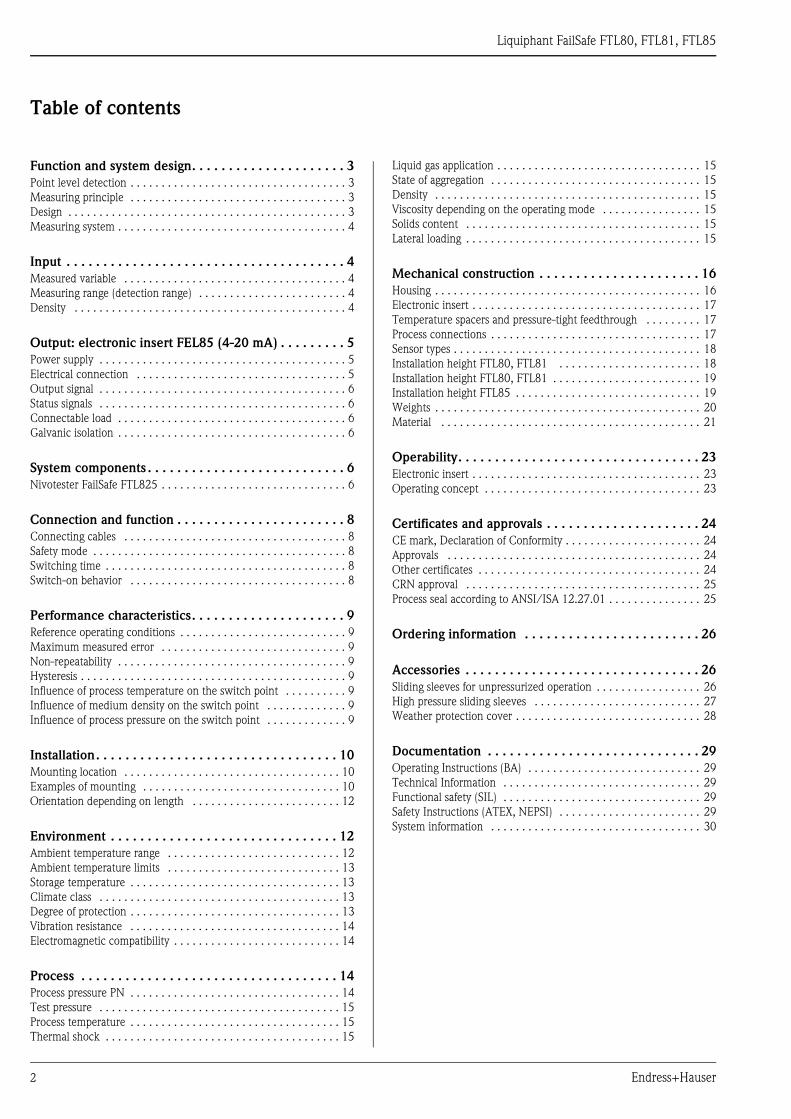
Function and system design. . . . . . . . . . . . . . . . . . . . . 3
Point level detection . . . . . . . . . . . . . . . . . . . . . . . . . . . . . . . . . . . 3
Measuring principle . . . . . . . . . . . . . . . . . . . . . . . . . . . . . . . . . . . 3
Design . . . . . . . . . . . . . . . . . . . . . . . . . . . . . . . . . . . . . . . . . . . . . 3
Measuring system . . . . . . . . . . . . . . . . . . . . . . . . . . . . . . . . . . . . . 4
Input . . . . . . . . . . . . . . . . . . . . . . . . . . . . . . . . . . . . . . 4
Measured variable . . . . . . . . . . . . . . . . . . . . . . . . . . . . . . . . . . . . 4
Measuring range (detection range) . . . . . . . . . . . . . . . . . . . . . . . . 4
Density . . . . . . . . . . . . . . . . . . . . . . . . . . . . . . . . . . . . . . . . . . . . 4
Output: electronic insert FEL85 (4-20 mA) . . . . . . . . . 5
Power supply . . . . . . . . . . . . . . . . . . . . . . . . . . . . . . . . . . . . . . . . 5
Electrical connection . . . . . . . . . . . . . . . . . . . . . . . . . . . . . . . . . . 5
Output signal . . . . . . . . . . . . . . . . . . . . . . . . . . . . . . . . . . . . . . . . 6
Status signals . . . . . . . . . . . . . . . . . . . . . . . . . . . . . . . . . . . . . . . . 6
Connectable load . . . . . . . . . . . . . . . . . . . . . . . . . . . . . . . . . . . . . 6
Galvanic isolation . . . . . . . . . . . . . . . . . . . . . . . . . . . . . . . . . . . . . 6
System components . . . . . . . . . . . . . . . . . . . . . . . . . . . 6
Nivotester FailSafe FTL825 . . . . . . . . . . . . . . . . . . . . . . . . . . . . . . 6
Connection and function . . . . . . . . . . . . . . . . . . . . . . . 8
Connecting cables . . . . . . . . . . . . . . . . . . . . . . . . . . . . . . . . . . . . 8
Safety mode . . . . . . . . . . . . . . . . . . . . . . . . . . . . . . . . . . . . . . . . . 8
Switching time . . . . . . . . . . . . . . . . . . . . . . . . . . . . . . . . . . . . . . . 8
Switch-on behavior . . . . . . . . . . . . . . . . . . . . . . . . . . . . . . . . . . . 8
Performance characteristics. . . . . . . . . . . . . . . . . . . . . 9
Reference operating conditions . . . . . . . . . . . . . . . . . . . . . . . . . . . 9
Maximum measured error . . . . . . . . . . . . . . . . . . . . . . . . . . . . . . 9
Non-repeatability . . . . . . . . . . . . . . . . . . . . . . . . . . . . . . . . . . . . . 9
Hysteresis . . . . . . . . . . . . . . . . . . . . . . . . . . . . . . . . . . . . . . . . . . . 9
Influence of process temperature on the switch point . . . . . . . . . . 9
Influence of medium density on the switch point . . . . . . . . . . . . . 9
Influence of process pressure on the switch point . . . . . . . . . . . . . 9
Installation. . . . . . . . . . . . . . . . . . . . . . . . . . . . . . . . . 10
Mounting location . . . . . . . . . . . . . . . . . . . . . . . . . . . . . . . . . . . 10
Examples of mounting . . . . . . . . . . . . . . . . . . . . . . . . . . . . . . . . 10
Orientation depending on length . . . . . . . . . . . . . . . . . . . . . . . . 12
Environment . . . . . . . . . . . . . . . . . . . . . . . . . . . . . . . 12
Ambient temperature range . . . . . . . . . . . . . . . . . . . . . . . . . . . . 12
Ambient temperature limits . . . . . . . . . . . . . . . . . . . . . . . . . . . . 13
Storage temperature . . . . . . . . . . . . . . . . . . . . . . . . . . . . . . . . . . 13
Climate class . . . . . . . . . . . . . . . . . . . . . . . . . . . . . . . . . . . . . . . 13
Degree of protection . . . . . . . . . . . . . . . . . . . . . . . . . . . . . . . . . . 13
Vibration resistance . . . . . . . . . . . . . . . . . . . . . . . . . . . . . . . . . . 14
Electromagnetic compatibility . . . . . . . . . . . . . . . . . . . . . . . . . . . 14
Process . . . . . . . . . . . . . . . . . . . . . . . . . . . . . . . . . . . 14
Process pressure PN . . . . . . . . . . . . . . . . . . . . . . . . . . . . . . . . . . 14
Test pressure . . . . . . . . . . . . . . . . . . . . . . . . . . . . . . . . . . . . . . . 15
Process temperature . . . . . . . . . . . . . . . . . . . . . . . . . . . . . . . . . . 15
Thermal shock . . . . . . . . . . . . . . . . . . . . . . . . . . . . . . . . . . . . . . 15
Liquid gas application . . . . . . . . . . . . . . . . . . . . . . . . . . . . . . . . . 15
State of aggregation . . . . . . . . . . . . . . . . . . . . . . . . . . . . . . . . . . 15
Density . . . . . . . . . . . . . . . . . . . . . . . . . . . . . . . . . . . . . . . . . . . 15
Viscosity depending on the operating mode . . . . . . . . . . . . . . . . 15
Solids content . . . . . . . . . . . . . . . . . . . . . . . . . . . . . . . . . . . . . . 15
Lateral loading . . . . . . . . . . . . . . . . . . . . . . . . . . . . . . . . . . . . . . 15
Mechanical construction . . . . . . . . . . . . . . . . . . . . . . 16
Housing . . . . . . . . . . . . . . . . . . . . . . . . . . . . . . . . . . . . . . . . . . . 16
Electronic insert . . . . . . . . . . . . . . . . . . . . . . . . . . . . . . . . . . . . . 17
Temperature spacers and pressure-tight feedthrough . . . . . . . . . 17
Process connections . . . . . . . . . . . . . . . . . . . . . . . . . . . . . . . . . . 17
Sensor types . . . . . . . . . . . . . . . . . . . . . . . . . . . . . . . . . . . . . . . . 18
Installation height FTL80, FTL81 . . . . . . . . . . . . . . . . . . . . . . . 18
Installation height FTL80, FTL81 . . . . . . . . . . . . . . . . . . . . . . . . 19
Installation height FTL85 . . . . . . . . . . . . . . . . . . . . . . . . . . . . . . 19
Weights . . . . . . . . . . . . . . . . . . . . . . . . . . . . . . . . . . . . . . . . . . . 20
Material . . . . . . . . . . . . . . . . . . . . . . . . . . . . . . . . . . . . . . . . . . 21
Operability. . . . . . . . . . . . . . . . . . . . . . . . . . . . . . . . . 23
Electronic insert . . . . . . . . . . . . . . . . . . . . . . . . . . . . . . . . . . . . . 23
Operating concept . . . . . . . . . . . . . . . . . . . . . . . . . . . . . . . . . . . 23
Certificates and approvals . . . . . . . . . . . . . . . . . . . . . 24
CE mark, Declaration of Conformity . . . . . . . . . . . . . . . . . . . . . . 24
Approvals . . . . . . . . . . . . . . . . . . . . . . . . . . . . . . . . . . . . . . . . . 24
Other certificates . . . . . . . . . . . . . . . . . . . . . . . . . . . . . . . . . . . . 24
CRN approval . . . . . . . . . . . . . . . . . . . . . . . . . . . . . . . . . . . . . . 25
Process seal according to ANSI/ISA 12.27.01 . . . . . . . . . . . . . . . 25
Ordering information . . . . . . . . . . . . . . . . . . . . . . . . 26
Accessories . . . . . . . . . . . . . . . . . . . . . . . . . . . . . . . . 26
Sliding sleeves for unpressurized operation . . . . . . . . . . . . . . . . . 26
High pressure sliding sleeves . . . . . . . . . . . . . . . . . . . . . . . . . . . 27
Weather protection cover . . . . . . . . . . . . . . . . . . . . . . . . . . . . . . 28
Documentation . . . . . . . . . . . . . . . . . . . . . . . . . . . . . 29
Operating Instructions (BA) . . . . . . . . . . . . . . . . . . . . . . . . . . . . 29
Technical Information . . . . . . . . . . . . . . . . . . . . . . . . . . . . . . . . 29
Functional safety (SIL) . . . . . . . . . . . . . . . . . . . . . . . . . . . . . . . . 29
Safety Instructions (ATEX, NEPSI) . . . . . . . . . . . . . . . . . . . . . . . 29
System information . . . . . . . . . . . . . . . . . . . . . . . . . . . . . . . . . . 30

Liquiphant FailSafe FTL80, FTL81, FTL85
Endress+Hauser 3
Function and system design
Point level detection Maximum or minimum detection for liquids in tanks or pipes (leak monitoring, dry running protection/pump
protection or overfill protection), particularly for the chemical, energy and oil & gas industry.
Special versions are suitable for use in hazardous areas and for applications with high pressures. As a coated
version, the Liquiphant FailSafe is highly resistant to corrosion, making it particularly suitable for very
aggressive liquids.
The point level switches make a distinction between two states: "covered" and "exposed"
Depending on whether you have selected the MIN (minimum detection) or MAX (maximum detection)
operating mode, this results in two specific scenarios in each case:
the "Good" state and demand mode.
"Good" state:
The fork is covered in the MIN operating mode (e.g. pump protection).
The fork is exposed (uncovered) in the MAX operating mode (e.g. overfill protection).
Demand mode:
The fork is exposed (uncovered) in the MIN operating mode (e.g. pump protection).
The fork is covered in the MAX operating mode (e.g. overfill protection).
A0018061
Measuring principle The sensor's fork vibrates at its intrinsic frequency. When the tuning fork is immersed in a liquid, its intrinsic
frequency changes due to the change in density of the surrounding medium. This change in frequency causes
the current signal to switch.
Design • FTL80: Compact
• FTL81: With pipe extension
• FTL85: With coated pipe extension (only flanged version)

Liquiphant FailSafe FTL80, FTL81, FTL85
4 Endress+Hauser
Measuring system
A0017999
1 Liquiphant FailSafe FTL8x with electronic insert FEL85 (4-20 mA)
2 Separate switching unit:
- Nivotester FailSafe FTL825
- PLC
- Safety PLC
- ...
3 Actuator
Input
Measured variable Point level (level)
Measuring range (detection
range)
The measuring range depends on the mounting point and the pipe extension, where applicable.
Density Setting on the electronic insert:
• MIN: 0.4 to 0 g/cm (0.4 to 0 SGU)
• MAX: 0.4 g/cm (0.4 SGU)
.
1 2
3
-
13 23 31
91 92
4 5 6 52
Liquiphant FailSafe FTL80, FTL81, FTL85
Endress+Hauser 5
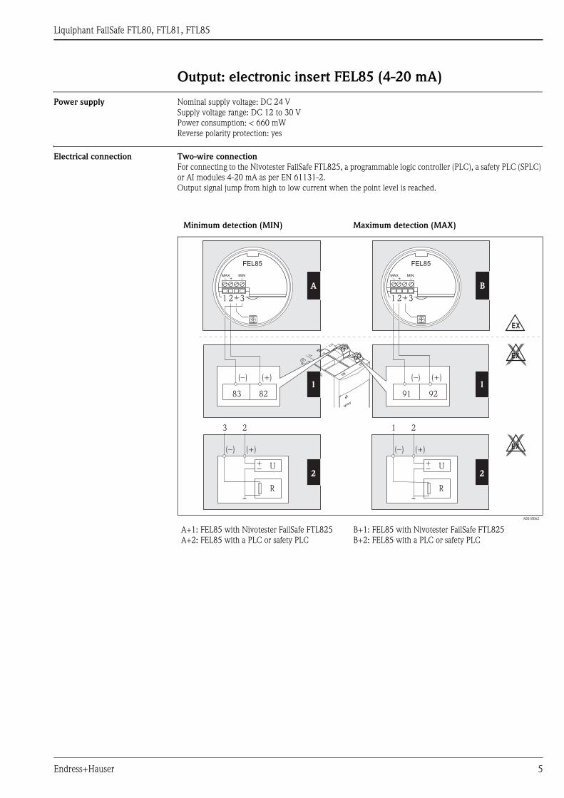
Output: electronic insert FEL85 (4-20 mA)
Power supply Nominal supply voltage: DC 24 V
Supply voltage range: DC 12 to 30 V
Power consumption: < 660 mW
Reverse polarity protection: yes
Electrical connection Two-wire connection
For connecting to the Nivotester FailSafe FTL825, a programmable logic controller (PLC), a safety PLC (SPLC)
or AI modules 4-20 mA as per EN 61131-2.
Output signal jump from high to low current when the point level is reached.
Minimum detection (MIN) Maximum detection (MAX)
A0018062
A+1: FEL85 with Nivotester FailSafe FTL825
A+2: FEL85 with a PLC or safety PLC
B+1: FEL85 with Nivotester FailSafe FTL825
B+2: FEL85 with a PLC or safety PLC
2
1
B
8
9
8
9
2
2
3
1
1 2 3 1 2 3
FEL85 FEL85
MAX MIN MAX MIN– + – – + –
(–) (–)(+) (+)
83 82 91 92
(–) (–)(+) (+)
+ +– –U U
R R
3 2 1 2
EX
A
EX
1
EX
2
Liquiphant FailSafe FTL80, FTL81, FTL85
6 Endress+Hauser
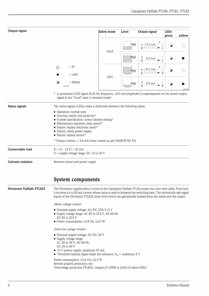
Output signal
* A permanent LIVE signal (0.25 Hz frequency, ±0.5 mA amplitude) is superimposed on the sensor output
signal in the "Good" state ( demand mode)
Status signals The status signals (LEDs) make a distinction between the following states:
• Operation: normal state
• Function check: end proof test*
• Outside specification: correct density setting*
• Maintenance required: clean sensor*
• Failure: replace electronic insert*
• Failure: check power supply
• Failure: replace device*
* Output current: < 3.6 mA (error current as per NAMUR NE 43)
Connectable load R = (U - 12 V) / 22 mA
U = supply voltage range: DC 12 to 30 V
Galvanic isolation Between sensor and power supply
System components
Nivotester FailSafe FTL825 The Nivotester supplies direct current to the Liquiphant FailSafe FTL8x sensor via a two-wire cable. From here
it receives a 4 to 20 mA current whose value is used to interpret the switching state. The intrinsically safe signal
inputs of the Nivotester FTL825 point level switch are galvanically isolated from the mains and the output.
Mains voltage version
• Nominal supply voltage: AC/DC 230/115 V
• Supply voltage range: AC 85 to 253 V, 50/60 Hz
DC 85 to 253 V
• Power consumption: 3.8 VA, 2.0 W
Extra-low voltage version
• Nominal supply voltage: AC/DC 24 V
• Supply voltage range:
AC 20 to 30 V, 50/60 Hz
DC 20 to 60 V
• D/C power supply: maximum 95 mA
• Permitted residual ripple inside the tolerance: Uss = maximum 2 V
Power consumption: 3.6 VA, 2.5 W
Reverse polarity protection: yes
Overvoltage protection FTL825: category II (2000 m (6562 ft) above MSL)
Safety mode Level Output signal LEDs
green yellow
A0018064
= lit
= unlit
= flashes
A0018063
MAX
MIN
+ -2 1+ -2 1
+ -2 1+ -2 1
+ -2 3+ -2 3
+ -2 3+ -2 3
13.5 mA
6.0 mA
18.5 mA
9.0 mA
*
*
Liquiphant FailSafe FTL80, FTL81, FTL85
Endress+Hauser 7
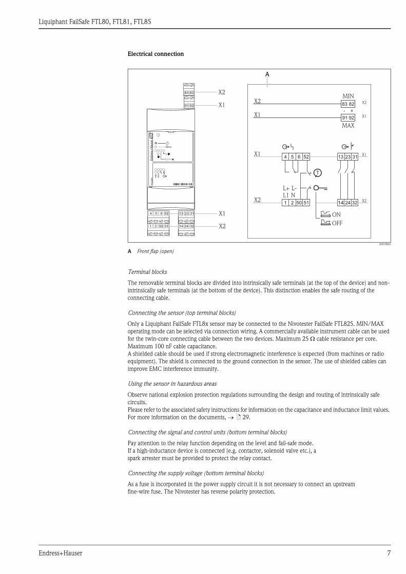
Electrical connection
A0018065
A Front flap (open)
Terminal blocks
The removable terminal blocks are divided into intrinsically safe terminals (at the top of the device) and non-
intrinsically safe terminals (at the bottom of the device). This distinction enables the safe routing of the
connecting cable.
Connecting the sensor (top terminal blocks)
Only a Liquiphant FailSafe FTL8x sensor may be connected to the Nivotester FailSafe FTL825. MIN/MAX
operating mode can be selected via connection wiring. A commercially available instrument cable can be used
for the twin-core connecting cable between the two devices. Maximum 25 cable resistance per core.
Maximum 100 nF cable capacitance.
A shielded cable should be used if strong electromagnetic interference is expected (from machines or radio
equipment). The shield is connected to the ground connection in the sensor. The use of shielded cables can
improve EMC interference immunity.
Using the sensor in hazardous areas
Observe national explosion protection regulations surrounding the design and routing of intrinsically safe
circuits.
Please refer to the associated safety instructions for information on the capacitance and inductance limit values.
For more information on the documents, ä 29.
Connecting the signal and control units (bottom terminal blocks)
Pay attention to the relay function depending on the level and fail-safe mode.
If a high-inductance device is connected (e.g. contactor, solenoid valve etc.), a
spark arrester must be provided to protect the relay contact.
Connecting the supply voltage (bottom terminal blocks)
As a fuse is incorporated in the power supply circuit it is not necessary to connect an upstream
fine-wire fuse. The Nivotester has reverse polarity protection.
1 2 50 51
524 5 6 13 31
14 3224 X2
X1
9291
8283
23
X1
X2
3214 24X2 X250 51
MIN
MAX
N1 2
L1L+ L-
83 82
91 92
X2 X2
X1 X1
- +
13 23 31X1 X1
6 524 5
ON
OFF
FT
L825
MIN
MA
X
A
Liquiphant FailSafe FTL80, FTL81, FTL85
8 Endress+Hauser
Output signal
• Relay outputs:
– Two floating NO contacts (supervised safety contacts based on the quiescent current principle) with an
integrated 3.15 A fuse (exchangeable)
Quiescent current operating mode: MIN/MAX (operating mode can be selected via connection wiring)
– One floating NC contact (signaling contact)
– Fault-signaling relay: floating changeover contact for error signaling
• Switching capacity per relay contact:
U ~ maximum 253 V
I ~ maximum 2 A
P ~ maximum 500 VA at cos 0.7
U = maximum 40 V
I = maximum 2 A
P = maximum 80 W
• Operating life: at least 105 switching operations with maximum contact load
• Recommended minimum current: 1 mA
• Function indicators: light emitting diodes for operation, point level and error
Signal on alarm
Safety contacts open, signaling contact closed, error signaled by red LED
Installation
Vertically on DIN top-hat rail (mounting rail (TS 35) as per EN 50022)
Dimensions
B/H/D: 45 mm (1.77 in), 108 mm (4.25 in), 112 mm (4.41 in)
Technical Information
More information on the FTL825 is available on our product pages at www.endress.com under Nivotester
FailSafe FTL825, document number: TI01027F
Connection and function
Connecting cables • Electronic insert: cross-section max. 2.5 mm (14 AWG)
• Maximum cable length: 1000 m ( 3281 ft)
• Maximum 25 cable resistance per core
• Maximum 100 nF cable capacitance
• Protective ground in housing: cross-section max. 2.5 mm(14 AWG)
• External equipotential bonding connection on housing: cross-section max. 4 mm(12 AWG)
Safety mode Minimum/maximum detection (MIN/MAX) can be selected by connection coding on the electronic insert
( ä 5, Electrical connection).
MAX = maximum detection:
The output switches in a safety-oriented manner when the probe is covered (demand mode).
For use with overfill protection for example
MIN = minimum detection:
The output switches in a safety-oriented manner when the probe is uncovered (demand mode).
For use with dry running protection, pump protection for example
Switching time • When fork is covered: approx. 0.5 s ±0.2 s
• When fork is exposed: approx. 1.0 s ±0.2 s
• Dwell time: at least 0.3 s
Switch-on behavior When switching on the power supply, the output assumes the alarm signal.
Operational after max. 4 s
Liquiphant FailSafe FTL80, FTL81, FTL85
Endress+Hauser 9
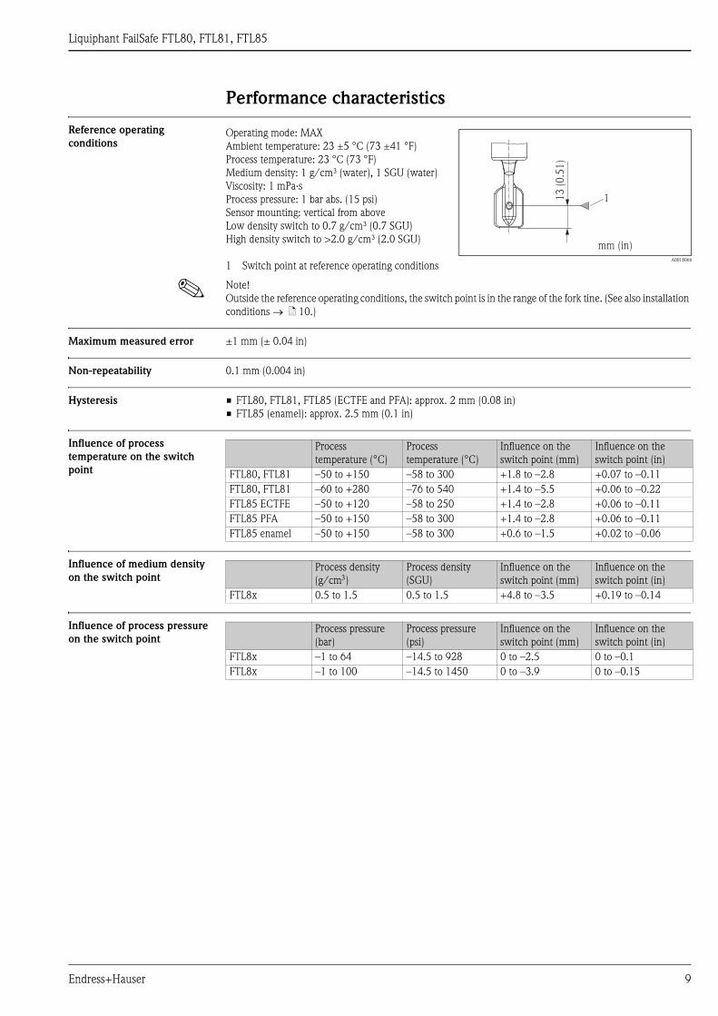
Performance characteristics
Reference operating
conditions
! Note!
Outside the reference operating conditions, the switch point is in the range of the fork tine. (See also installation
conditions ä 10.)
Maximum measured error ±1 mm (± 0.04 in)
Non-repeatability 0.1 mm (0.004 in)
Hysteresis • FTL80, FTL81, FTL85 (ECTFE and PFA): approx. 2 mm (0.08 in)
• FTL85 (enamel): approx. 2.5 mm (0.1 in)
Influence of process
temperature on the switch
point
Influence of medium density
on the switch point
Influence of process pressure
on the switch point
Operating mode: MAX
Ambient temperature: 23 ±5 °C (73 ±41 °F)
Process temperature: 23 °C (73 °F)
Medium density: 1 g/cm³ (water), 1 SGU (water)
Viscosity: 1 mPa·s
Process pressure: 1 bar abs. (15 psi)
Sensor mounting: vertical from above
Low density switch to 0.7 g/cm³ (0.7 SGU)
High density switch to >2.0 g/cm³ (2.0 SGU)
1 Switch point at reference operating conditionsA0018066
13
(0
.51
)
1
mm (in)
Process
temperature (°C)
Process
temperature (°C)
Influence on the
switch point (mm)
Influence on the
switch point (in)
FTL80, FTL81 –50 to +150 –58 to 300 +1.8 to –2.8 +0.07 to –0.11
FTL80, FTL81 –60 to +280 –76 to 540 +1.4 to –5.5 +0.06 to –0.22
FTL85 ECTFE –50 to +120 –58 to 250 +1.4 to –2.8 +0.06 to –0.11
FTL85 PFA –50 to +150 –58 to 300 +1.4 to –2.8 +0.06 to –0.11
FTL85 enamel –50 to +150 –58 to 300 +0.6 to –1.5 +0.02 to –0.06
Process density
(g/cm)
Process density
(SGU)
Influence on the
switch point (mm)
Influence on the
switch point (in)
FTL8x 0.5 to 1.5 0.5 to 1.5 +4.8 to –3.5 +0.19 to –0.14
Process pressure
(bar)
Process pressure
(psi)
Influence on the
switch point (mm)
Influence on the
switch point (in)
FTL8x –1 to 64 –14.5 to 928 0 to –2.5 0 to –0.1
FTL8x –1 to 100 –14.5 to 1450 0 to –3.9 0 to –0.15

Liquiphant FailSafe FTL80, FTL81, FTL85
10 Endress+Hauser
Installation
Mounting location Switch points on the sensor depend on the mounting position (outside reference operating conditions).
A0018183
A Mounting from above
B Mounting from below
C Mounting from the side
Examples of mounting Examples of mounting with regard to the viscosity of the liquid and the tendency to form buildup
Optimum mounting, trouble-free even with high viscosity
Position the fork so that the narrow edge of the tines is vertical to ensure that the liquid can run off easily.
A0018184
A Vertical from above
B Flush-mounted from the side
With buildup on the tank walls
* Ensure that there is sufficient distance between the buildup expected on the tank wall and the fork.
A0018185
A Vertical from above
B Protruding into the tank from the side
A B C
38
(1
.5)
38
(1
.5)
18
(0
.71
)
18
(0
.71
)
7 (
0.2
8)
7 (
0.2
8)
mm (in)
A B
*
*
A B
Liquiphant FailSafe FTL80, FTL81, FTL85
Endress+Hauser 11
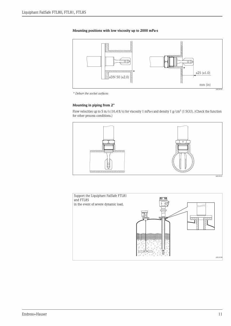
Mounting positions with low viscosity up to 2000 mPa·s
A0018186
* Deburr the socket surfaces
Mounting in piping from 2"
Flow velocities up to 5 m/s (16.4 ft/s) for viscosity 1 mPa·s and density 1 g/cm (1 SGU). (Check the function
for other process conditions.)
A0018187
**
mm (in)
≥ ≥( 1.0)25
≥ ≥( 2.0)DN 50
Support the Liquiphant FailSafe FTL81
and FTL85
in the event of severe dynamic load.
A0018188

Liquiphant FailSafe FTL80, FTL81, FTL85
12 Endress+Hauser
Orientation depending on
length
<500 mm (<20 in): any orientation
>500 mm (>20 in): vertical
Environment
Ambient temperature range Version with maximum process temperature of 150 °C (300 °F)
Permitted ambient temperature Ta at the housing depending on the process temperature Tp in the tank:
• Ta –40 °C (–40 °F) standard
• Ta –50 °C (–58 °F) optional
! Note! FTL85
The temperature difference between the process temperature and ambient temperature (Tp - Ta) of the flange
may not exceed 60 °C (140 °F) for switches with ECTFE or PFA coating. The flange has to be included in the
tank insulation where necessary.
Ensure adequate space outside the
tank for mounting, connection and
configuration.
A0018189
.. .. .. .. .. .. .. .. .. .. .. .. .. .. .. .. .. .. .. .. .. .. .. .. .. .. .. .. .. .... .. .. .. .. .. .. .. .. .. .. .. .. .. .. .. .. .. .. .. .. .. .. .. .. .. .. .. .. .. ... .. .. .. .. .. .. .. .. .. .. .. .. .. .. .. .. .. .. .. ... .. .. .. .. .. .. .. .. .. .. .. .. .. .. .. .. .. .. .. ..
.. .. .. .. .. .. .. .. .. .. .. .. .. .. .. .. .. .. .. .. .. .. .. .. .. .. .. .. .. .. .. .. .. .. .. .. .. .. .. .. .. .. .. .. .. .. .. .. .. .. .. .. .. .. .. .. .. .. .. .
.. .. .. .. .. .. .. .. .. .. .. .. .. .. .. .. .. .. .. .. .. .. .. .. .. .. .. .. .. .. .. .. .. .. .. .. .. .. .. .. ..
.. .. .. .. .. .. .. .. .. .. .. .. .. .. .. .. .. .. .. .. .. .. .. .. .. .. .. .. .. ... .. .. .. .. .. .. .. .. .. .. .. .. .. .. .. .. .. .. .. .. .. .. .. .. .. .. .. .. .. .
.. .. .. .. .. .. .. .. .. .. .. .. .. .. .. .. .. .. .. .. ... .. .. .. .. .. .. .. .. .. .. .. .. .. .. .. .. .. .. .. .. ..
.. .. .. .. .. .. .. .. .. .. .. .. .. .. .. .. .. .. .. .. .. .. .. .. .. .. .. .. .. .. .. .. .. .. .. .. .. .. .. .. .. .. .. .. .. .. .. .. .. .. .. .. .. .. .. .. .. .. .. .
.. .. .. .. .. .. .. .. .. .. .. .. .. .. .. .. .. .. .. .. .. .. .. .. .. .. .. .. .. .. .. .. .. .. .. .. .. .. .. .. ..
A0018190
1 Maximum ambient temperature in hazardous areas (T6) and with intrinsically safe power
2 Additional temperature range for devices with a temperature spacer or pressure-tight feedthrough
Ta
Tp
Ta
+50
+70
0
–50 Tp
[°C]0 +90–50 +150
[°C]
+32 +190–58 +300
+120
+160
+32
–58
[°F]
[°F]
21
+60+140

Liquiphant FailSafe FTL80, FTL81, FTL85
Endress+Hauser 13
Version with maximum process temperature of 230/280 °C (450/540 °F)
(only FTL80 and FTL81)
A0018191
A Temperature spacer outside insulation
B Temperature spacer inside insulation
1 Maximum ambient temperature in hazardous areas (T6) and with intrinsically safe power
2 Maximum 50 cumulative hours
Ambient temperature limits –40 to +70 °C (–40 to +160 °F)
Optional: –50 to +70 °C (–58 to 160 °F) and –60 to +70 °C (–76 to 160 °F)
Storage temperature –50 to +80 °C (–58 to 176 °F)
Climate class Climate protection to IEC 60068, Part 2-38, Fig. 2a
Degree of protection
Tp
Ta
+50
+70
0
– 60 Tp
[°C]0– 60 +300
[°C]
+32 +450–76 +570
+160
[°F]
[°F]
2
1
+60+140
Ta
+120
+280+230
+32
+540
A
Ta
+50
+70
0
– 60 Tp
[°C]0– 60 +300
[°C]
+32 +370– 76 +570
+160
[°F]
[°F]
2
1
+60+140
+120
+280+190
+32
+540
Tp
Ta
B
– 76
+230
+450
– 76
Types of housing IP66* IP67* IP68* NEMA**
Polyester housing F16 X X – 4X
Stainless steel housing F15 X X – 4X
Aluminum housing F17 X X – 4X
Aluminum housing F13 X – X 4X/6P
Stainless steel housing F27 X – X 4X/6P
Aluminum housing T13
with separate connection compartment (Ex d)
X – X 4X/6P
* As per EN60529; ** As per NEMA 250

Liquiphant FailSafe FTL80, FTL81, FTL85
14 Endress+Hauser
Vibration resistance As per IEC 60068-2-64, load class 1 (m/s²)²/Hz, 3 x 100 minutes
Electromagnetic compatibility Electromagnetic compatibility in accordance with all of the relevant requirements in the EN 61326 series and
NAMUR Recommendation NE 21 EMC. Please refer to the Declaration of Conformity for details.
1 % span 160 μA
Process
Process pressure PN FTL80, FTL81:
A0018192
1 Allowed pressure rating when the "100 bar (1450 psi)" option is selected (FTL81)
FTL80, FTL81 (230/280 °C (450/540 °F)):
A0018193
Only with high-temperature version
PN
+100
Tp
[°C]0 +150
[bar]
+32 +300
[psi]
[°F]
1
+1450
+64+928
–1–14.5
–50
–58
+100
[bar][psi]
+1450
+63+914
–1–14.5
[°C]0 +260
+32 +500 [°F]
–60
–76
+280
+540
PN

Liquiphant FailSafe FTL80, FTL81, FTL85
Endress+Hauser 15
! Note!
Please refer to the standards listed for the permitted pressure values of the flanges at higher temperatures:
• pR EN 1092-1: 2005
With regard to their stability-temperature property, the materials 1.4435 and 1.4404 are identical and are
grouped together under 13E0 in EN1092-1 Tab. 18. The chemical composition of the two materials can be
identical.
• ASME B 16.5a - 2009 Tab. 2.2.3 F316L
• ASME B 16.5a - 2009 Tab. 2.3.8 N06022 and N06455
• JIS B 2220
The lowest value from the derating curves of the device and selected flange applies in each case.
Test pressure FTL80/81 (pN = 64 bar (960 psi)): 100 bar (1450 psi) 1.5 times the process pressure pN;
no function during test pressure; burst pressure >200 bar (>2900 psi)
FTL80/81 (pN = 100 bar (1450 psi)): 150 bar (2250 psi) 1.5 times the process pressure pN;
no function during test pressure; burst pressure >400 bar (>5800 psi)
FTL85 (pN = 25 or 40 bar (363 or 580 psi)): 38 or 60 bar (550 or 870 psi)
1.5 times the process pressure pN; no function during test pressure; burst pressure >400 bar (>5800 psi)
Process temperature • FTL80, FTL81
–50 to +150 °C (–58 to +300 °F)
–60 to +280 °C (–76 to +540 °F) (high-temperature version: 300 °C (572 °F) for a maximum of 50
cumulative hours)
• FTL85
ECTFE: –50 to +120 °C (–58 to +248 °F)
PFA: –50 to +150 °C (–58 to +300 °F)
Enamel: –50 to +150 °C (–58 to +300 °F)
Thermal shock Maximum 120 °C/s (300 °F/s) without restriction within the process temperature range)
Liquid gas application Process temperature: –50 to +60 °C (–58 to +140 °F)
State of aggregation Liquid
Density The density is set at two rotary switches ("Low" density and "High" density).
! Note!
Other density setting combinations are not permitted.
Viscosity depending on the
operating mode
MAX: 10000 mPa·s
MIN: 350 mPa·s
MIN: coating, high temperature (230/280 °C (450/536 °F)) 100 mPa·s
Solids content Maximum ø5 mm (0.2 in)
Lateral loading 75 Nm (55.32 lbf ft)
FTL85
ECTFE PFA Enamel
–1 to +40 bar (–14.5 to 580 psi) –1 to +40 bar (–14.5 to 580 psi) –1 to +25 bar (–14.5 to 360 psi)
MAX Medium "Low" density in g/cm (SGU)
LOW
"High" density in g/cm(SGU)
HIGH
Combination 1 Liquefied gas 0.4 (0.4) 2.0 (2.0)
Combination 2 Other liquids 0.7 (0.7) > 2.0 (> 2.0)
MIN Medium "Low" density in g/cm
(SGU) LOW
"High" density in g/cm(SGU)
HIGH
Combination 1 Liquefied gas 0.4 (0.4) 0.7 (0.7)
Combination 2 e.g. alcohol 0.6 (0.6) 0.9 (0.9)
Combination 3 e.g. water 0.7 (0.7) 1.2 (1.2)
Combination 4 e.g. acid 0.9 (0.9) 2.0 (2.0)

Liquiphant FailSafe FTL80, FTL81, FTL85
16 Endress+Hauser
Mechanical construction
! Note!
All dimensions in mm (in)!
Housing * Cover with sight glass (optional).
Polyester housing F16
A0018195
Stainless steel housing F15
A0018196
Aluminum housing F17
A0018197
Aluminum housing F13**
Stainless steel housing F27**
** Bolted connetion to sensor.
A0018199
Aluminum housing T13
with separate connection
compartment
A0018200
ø85 (3.4) �76 (3.0)
~1
00
(3
.9)
ø76 (3) �64 (2.5)
~9
5 (
3.7
)
~1
14
(4
.5)*
ø80 (3.2) �60 (2.4)
�65 (2.6)
~105 (
4.1
)
~119 (
4.7
)*
ø80 (3.2) �60 (2.4)
�65 (2.6)
~1
18
(4
.7)
~1
47
(5
.8)*
�65 (2.6) �97 (3.8)
~1
35
(5
.3)
~1
48
(5
.8)*

Liquiphant FailSafe FTL80, FTL81, FTL85
Endress+Hauser 17
Electronic insert
Temperature spacers and
pressure-tight feedthrough
Process connections
FEL85
A0018201
Output 4-20 mA for separate switching unit Nivotester FailSafe FTL825 or PLC/
SPLC
Temperature
spacer
Pressure-tight
feedthrough
(second line of
defense)
Temperature spacer including welded
gas-tight feedthrough
A0018213 A0018214
Maximum temperature 150 °C (300 °F) <230 °C (450 °F) <280 °C (540 °F)
Temperature spacer: for bypassing any existing tank insulation. The additional distance to the process reduces the
ambient temperature present at the housing.
Pressure-tight feedthrough: sealed with an O-ring. Recommended if there is a risk of damage to the sensor particularly
in the case of dangerous media or where there is medium to high probability of condensation forming.
Pressure-tight feedthrough: welded diffusion-resistant glass feedthrough. Recommended if there is a risk of damage to
the sensor particularly in the case of dangerous and very dangerous media or where there is a high probability of
condensation forming.
Thread G
cylindricalThread R, NPT
taperedFlanges FTL80, FTL81 Flanges FTL85 (coated)
A0018215 A0018216A0018217
Thread size ¾ 1* ¾ 1 -- --
Width across flats (SW = AF) 32 41 32 41 -- --
Standard DIN EN ISO228-I DIN 2999 (R)
ANSI B 1.20.1 (NPT)
ANSI B 16.5 (RF)
EN 1092-1 (Form A/B)/DIN 2527 B
JIS B 2220 (RF)
For pressures (bar (psi)) to 100 (1450) 100 (1450) 100 (1450) See nominal pressure of flange,
however
ECTFE and PFA (Edlon**): 40 (580)
Enamel: 25 (360)
For temperatures (°C (°F)) to 280 (5410) 280 (5410) 280 (5410) ECTFE: 120 (250)
PFA (Edlon**): 150 (300)
Enamel: 150 (300)
Seals Elastomer flat seal to
DIN7603
-- Depending on design:
provided by the customer
Synthetic coating:
PTFE seal supplied
Enamel coating: seal provided by the
customer
* Please beware of pressure and temperature specifications if installing in weld-in adapter! ä 29 "Technical Information" Weld-in adapter
** FDA-compliant material in accordance with 21 CFR Part 177.1550/2600

Liquiphant FailSafe FTL80, FTL81, FTL85
18 Endress+Hauser
Sensor types
Installation height FTL80,
FTL81
Compact
FTL80
Pipe
extension
FTL81
FTL85
Short pipe
version
FTL81
FTL85
Compact or with pipe extension up to 3 m (10 ft)
A0018218
Note:
The Liquiphant FailSafe FTL8x has different switch points to its predecessor the Liquiphant FailSafe FDL6x.
Special length "short pipe version"
With vertical mounting the switch point is the same as for the Liquiphant FailSafe FDL60
"L" depends on process connection:
L = 115 mm (4.5 in) for flanges and flange-like process connections
L = 99 mm (4.0 in) for threads NPT and R (BSPT)
L = 118 mm (4.7 in) for threads G1 (BSP 1)
L = 115 mm (4.5 in) for threads G ¾ (BSP ¾)
L = 104 mm (4.1 in) for flush-mounted 1" (Endress+Hauser)
Drawing Number Description Housing
F16 F15 F17 F27 F13 T13
A0018219
1Cover with sight glass
(optional)0 19 14 29 13
2 Housing with cover 100 95 105 118 135
3
Temperature spacer
to 150 °C (optional)
140Pressure-tight feedthrough
Pressure-tight feedthrough
sealed with an O-ring
(optional)
4**
Thread G 3/420 15
Thread G 1
Thread R 3/4
41 38Thread R 1
Thread NPT 3/4
Thread NPT 1
Flange 55 64
Thread Flange
G
3/4
G
1
G
1***
R, NPT
3/4
R, NPT
1
5
Short pipe version 115 118 104 99 115
Pipe extension* 148 to 3000
Sensor (compact)** 66.5 69 80 50.5 66.5
* Can only be selected for FTL81.
** To seal surface for G thread and flange or lower edge of thread for NPT and R thread.
*** When flush-mounted.
1
2
3
4
5

Liquiphant FailSafe FTL80, FTL81, FTL85
Endress+Hauser 19
Installation height FTL80,
FTL81
High-temperature version (230/280 °C (450/540 °F))
Installation height FTL85 Coated version
Drawing Number Description Housing
F16 F15 F17 F27 F13 T13
A0018220
1Cover with sight glass
(optional)0 19 14 29 13
2 Housing with cover 100 95 105 118 135
3
Temperature spacer
to 230 °C + pressure-tight
feedthrough (welded diffusion-
resistant glass feedthrough)
163
Temperature spacer
to 280 °C + pressure-tight
feedthrough (welded diffusion-
resistant glass feedthrough)
203
4**
Thread G 3/417
Thread G 1
Thread R 3/4
37Thread R 1
Thread NPT 3/4
Thread NPT 1
Flange As per flange standard
Thread Flange
G
3/4
G
1
R, NPT
3/4
R, NPT
1
5Pipe extension* 148 to 3000
Sensor (compact)** 66.5 69 50.5 66.5
* Can only be selected for FTL81.
** To seal surface for G thread and flange or lower edge of thread for NPT and R thread.
1
2
4
5
1
2
3
4
5
Drawing Number Description Housing
F16 F15 F17 F27 F13 T13
A0018221
1Cover with sight glass
(optional)0 19 14 29 13
2 Housing with cover 100 95 105 118 135
3
Temperature spacer
to 150 °C (optional)
140Pressure-tight feedthrough
Pressure-tight feedthrough
sealed with an O-ring (optional)
4Flange 55 64
5
Short pipe version 115
Pipe extension 148 to 3000
1
2
3
1
2
3
4
55

Liquiphant FailSafe FTL80, FTL81, FTL85
20 Endress+Hauser
Weights The total weight of a typical Liquiphant FailSafe device can be calculated by adding the individual components
to the basic weight.
Basic weight Weight in
kg (lbs)
The basic weight comprises:
• Sensor (compact)
• Thread G ¾
• Electronic insert
• Polyester housing F16
• Housing cover
0.7 (1.5)
Housing kg (lbs)
Aluminum housing F13 (connection: NPT¾, G½ or M20) 0.5 (1.1)
Stainless steel housing F15 (connection: NPT½, G½, M20 or M12 connector) 0.1 (0.2)
Aluminum housing F17 (connection: NPT¾, G½, M20 or M12 connector) 0.5 (1.1)
Stainless steel housing F27 (connection: NPT½, G½ or M20) 0.3 (0.7)
Aluminum housing T13 with separate connection compartment (connection: NPT¾, G½ or M20) 0.9 (2)
Temperature spacer kg (lbs)
1 piece 0.6 (1.3)
Pressure-tight feedthrough kg (lbs)
1 piece 0.7 (1.54)
Process connection: threaded connection kg (lbs)
G ¾, 316L, thread ISO 228 *
G ¾, AlloyC22, thread ISO 228 *
G 1, 316L, thread ISO 228 0.2 (0.4)
G 1, AlloyC22, thread ISO 228 0.2 (0.4)
R ¾, 316L, thread DIN 2999 *
R ¾, AlloyC22, thread DIN 2999 *
R 1, 316L, thread DIN 2999 0.2 (0.4)
R 1, AlloyC22, thread DIN 2999 0.2 (0.4)
NPT ¾, 316L, thread ANSI *
NPT ¾, AlloyC22, thread ANSI *
NPT 1, 316L, thread ANSI 0.2 (0.4)
NPT 1, AlloyC22, thread ANSI 0.2 (0.4)
* Included in the basic weight
Process connection: EN flanges kg (lbs)
DN25 PN25/40 A, 316L, flange EN 1092-1 (DIN 2527 B) 1.4 (3.1)
DN25 PN25/40 B1, 316Lflange EN 1092-1 (DIN 2527 C) 1.3 (2.9)
DN25 PN25/40 B1, AlloyC22 >1.4462flange EN 1092-1 (DIN 2527) 1.3 (2.9)
DN25 PN40 B1, 316L, flange EN 1092-1 (DIN 2526 D) 1.4 (3.1)
DN32 PN25/40 A316L, flange EN 1092-1 (DIN 2527 B) 2.0 (4.4)
DN40 PN25/40 A316L, flange EN 1092-1 (DIN 2527 B) 2.4 (5.3)
DN50 PN10/16 B1316L, flange EN 1092-1 (DIN 2527 C) 2.5 (5.5)
DN50 PN25/40 A316L, flange EN 1092-1 (DIN 2527 B) 3.2 (7.1)
DN50 PN25/40 B1316L, flange EN 1092-1 (DIN 2527 C) 2.9 (6.4)
DN50 PN40 B1, 316L, flange EN 1092-1 (DIN 2526 D) 2.9 (6.4)
DN50 PN25/40 B1, AlloyC22 >1.4462, flange EN 1092-1 (DIN 2527) 2.9 (6.4)
DN50 PN63 A, 316L, flange EN 1092-1 (DIN 2527 B) 4.5 (9.9)
DN50 PN63 B2, 316L, flange EN 1092-1 (DIN 2527 E) 4.5 (9.9)
DN50 PN63 B1, AlloyC22 >1.4462, flange EN 1092-1 (DIN 2527) 4.5 (9.9)
DN50 PN100 A, 316L, flange EN 1092-1 5.5 (12.1)
DN50 PN100 B2, 316L, flange EN 1092-1 5.5 (12.1)
DN65 PN25/40 A316L, flange EN 1092-1 (DIN 2527 B) 4.3 (9.5)
DN80 PN10/16 B1316L, flange EN 1092-1 (DIN 2527 C) 4.8 (10.6)
DN80 PN25/40 A316L, flange EN 1092-1 (DIN 2527 B) 5.9 (13)
DN80 PN25/40 B1316L, flange EN 1092-1 (DIN 2527 C) 5.2 (11.5)
DN80 PN40 B1, 316L, flange EN 1092-1 (DIN 2526 D) 5.2 (11.5)
DN80 PN25/40 B1, AlloyC22 >1.4462, flange EN 1092-1 (DIN 2527) 5.2 (11.5)
DN80 PN63 A, 316Ti, flange EN 1092-1 (DIN 2527 B) 6.9 (15.2)
DN80 PN63 B2, 316L, flange EN 1092-1 (DIN 2527 E) 6.9 (15.2)
DN80 PN63 B1, AlloyC22 >1.4462, flange EN 1092-1 (DIN 2527) 6.9 (15.2)
Liquiphant FailSafe FTL80, FTL81, FTL85
Endress+Hauser 21
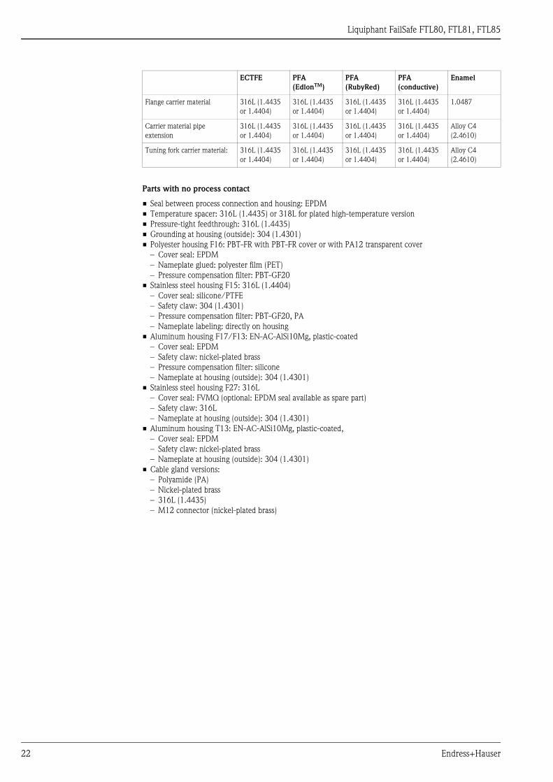
Material Material specifications as per AISI and DIN-EN.
Parts in contact with process in FTL80, FTL81
• Process connection and pipe extension: 316L (1.4435) optionally 2.4602 (AlloyC22)
• Tuning fork:
– High-temperature version 318L (1.4462); optionally 2.4602 (AlloyC22)
– Standard version 316L (1.4435); optionally 2.4602 (AlloyC22)
• Flanges: 316L (1.4435 or 1.4404)
• Flange plating: AlloyC22
– High-temperature version carrier material 318L (1.4462)
– Standard version carrier material 316L (1.4435 or 1.4404)
• Flat seal for process connection G ¾ or G 1: fiber-reinforced elastomer seal, asbestos-free
Parts in contact with process in FTL85
DN80 PN100 A, 316L, flange EN 1092-1 8.0 (17.6)
DN80 PN100 B2, 316L, flange EN 1092-1 8.0 (17.6)
DN100 PN10/16 B1, 316L, flange EN 1092-1 (DIN 2527 C) 5.3 (11.7)
DN100 PN25/40 A, 316L, flange EN 1092-1 (DIN 2527 B) 7.5 (16.5)
DN100 PN63 A, 316L, flange EN 1092-1 (DIN 2527 B) 10.1 (22.3)
DN100 PN63 B2, 316L, flange EN 1092-1 (DIN 2527 E) 10.1 (22.3)
DN100 PN63 B1, AlloyC22 >1.4462flange EN 1092-1 (DIN 2527) 10.1 (22.3)
Process connection: ANSI flanges kg (lbs)
1" 150 lbs RF, 316/316L, flange ANSI B16.5 1.0 (2.2)
1¼" 300 lbs RF, 316/316L, flange ANSI B16.5 2.0 (4.4)
1½" 150 lbs RF,316/316L, flange ANSI B16.5 1.5 (3.3)
1½" 300 lbs RF, 316/316L, flange ANSI B16.5 2.7 (6.0)
2" 150 lbs RF, 316/316L, flange ANSI B16.5 2.4 (5.3)
2" 150 lbs RF, AlloyC22 >1.4462, flange ANSI B16.5 2.4 (5.3)
2" 300 lbs RF, 316/316L, flange ANSI B16.5 3.2 (7.1)
2" 300 lbs RF, AlloyC22 >1.4462, flange ANSI B16.5 3.2 (7.1)
2" 600 lbs RF, 316/316L, flange ANSI B16.5 4.2 (9.3)
2" 600 lbs RF, AlloyC22 >1.4462, flange ANSI B16.5 4.2 (9.3)
3" 150 lbs RF, 316/316L, flange ANSI B16.5 4.9 (10.8)
3" 300 lbs RF, 316/316L, flange ANSI B16.5 6.8 (15)
3" 600 lbs RF, 316/316L, flange ANSI B16.5 8.5 (18.7)
3" 600 lbs RF, AlloyC22 >1.4462, flange ANSI B16.5 8.5 (18.7)
4" 150 lbs RF, 316/316L, flange ANSI B16.5 7.0 (15.4)
4" 300 lbs RF, 316/316L, flange ANSI B16.5 11.5 (25.4)
4" 600 lbs RF, 316/316L, flange ANSI B16.5 17.3 (38.2)
Process connection: JIS flanges kg (lbs)
20 K 50 RF, 316L, flange JIS B2220 1.9 (4.2)
20 K 50RF, AlloyC22 >316L, flange JIS B2220 1.9 (4.2)
Pipe extension kg (lbs)
1 m 0.9 (2)
100 in 2.3 (5.1)
Weather protection cover kg (lbs)
1 piece 0.3 (0.7)
Process connection: EN flanges kg (lbs)
ECTFE PFA
(EdlonTM)
PFA
(RubyRed)
PFA
(conductive)
Enamel
Layer thickness: Lower limit 0.5 mm (0.02
in)
0.45 mm
(0.02 in)
0.45 mm
(0.02 in)
0.45 mm
(0.02 in)
0.4 mm
(0.02 in)
Layer thickness: Upper limit 1.6 mm
(0.06 in)
1.6 mm
(0.06 in)
1.6 mm
(0.06 in)
1.6 mm
(0.06 in)
0.8 mm
(0.3 in)
Liquiphant FailSafe FTL80, FTL81, FTL85
22 Endress+Hauser
Parts with no process contact
• Seal between process connection and housing: EPDM
• Temperature spacer: 316L (1.4435) or 318L for plated high-temperature version
• Pressure-tight feedthrough: 316L (1.4435)
• Grounding at housing (outside): 304 (1.4301)
• Polyester housing F16: PBT-FR with PBT-FR cover or with PA12 transparent cover
– Cover seal: EPDM
– Nameplate glued: polyester film (PET)
– Pressure compensation filter: PBT-GF20
• Stainless steel housing F15: 316L (1.4404)
– Cover seal: silicone/PTFE
– Safety claw: 304 (1.4301)
– Pressure compensation filter: PBT-GF20, PA
– Nameplate labeling: directly on housing
• Aluminum housing F17/F13: EN-AC-AlSi10Mg, plastic-coated
– Cover seal: EPDM
– Safety claw: nickel-plated brass
– Pressure compensation filter: silicone
– Nameplate at housing (outside): 304 (1.4301)
• Stainless steel housing F27: 316L
– Cover seal: FVMQ (optional: EPDM seal available as spare part)
– Safety claw: 316L
– Nameplate at housing (outside): 304 (1.4301)
• Aluminum housing T13: EN-AC-AlSi10Mg, plastic-coated,
– Cover seal: EPDM
– Safety claw: nickel-plated brass
– Nameplate at housing (outside): 304 (1.4301)
• Cable gland versions:
– Polyamide (PA)
– Nickel-plated brass
– 316L (1.4435)
– M12 connector (nickel-plated brass)
Flange carrier material 316L (1.4435
or 1.4404)
316L (1.4435
or 1.4404)
316L (1.4435
or 1.4404)
316L (1.4435
or 1.4404)
1.0487
Carrier material pipe
extension
316L (1.4435
or 1.4404)
316L (1.4435
or 1.4404)
316L (1.4435
or 1.4404)
316L (1.4435
or 1.4404)
Alloy C4
(2.4610)
Tuning fork carrier material: 316L (1.4435
or 1.4404)
316L (1.4435
or 1.4404)
316L (1.4435
or 1.4404)
316L (1.4435
or 1.4404)
Alloy C4
(2.4610)
ECTFE PFA
(EdlonTM)
PFA
(RubyRed)
PFA
(conductive)
Enamel
Liquiphant FailSafe FTL80, FTL81, FTL85
Endress+Hauser 23
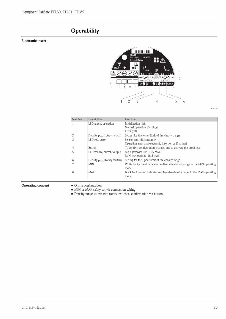
Operability
Electronic insert
A0018032
Operating concept • Onsite configuration
• MIN or MAX safety set via connection wiring
• Density range set via two rotary switches, confirmation via button
Number Description Function
1 LED green, operation Initialization (lit),
Normal operation (flashing),
Error (off)
2 Density low (rotary switch) Setting for the lower limit of the density range
3 LED red, error Sensor error (lit constantly),
Operating error and electronic insert error (flashing)
4 Button To confirm configuration changes and to activate the proof test
5 LED yellow, current output MAX (exposed) lit (13.5 mA),
MIN (covered) lit (18.5 mA)
6 Density high (rotary switch) Setting for the upper limit of the density range
7 MIN White background indicates configurable density range in the MIN operating
mode
8 MAX Black background indicates configurable density range in the MAX operating
mode
MIN –
FEL85U= 24 (12 ... 30) VDCI = 4...20 mA
I >12mA
MAX– +
0.4 2,00.7 2.0
0.6 0.9
0.9 2.0
0.7 1,2
0.4 0.7
>
�High
�Low
3
1 2 3 4 5 6
7
8
Liquiphant FailSafe FTL80, FTL81, FTL85
24 Endress+Hauser
Certificates and approvals
CE mark, Declaration of
Conformity
The devices are designed to meet state-of-the-art safety requirements, have been tested, and left the factory in
a condition in which they are safe to operate. The devices comply with the applicable standards and regulations
that are listed in the EC Declaration of Conformity and thus meet the legal requirements of the EC Directives.
Endress+Hauser confirms the conformity of the device by affixing to it the CE mark.
Approvals
Other certificates Material certificates
• EN 10204 - 3.1 material (wetted metal parts) inspection certificate
• EN 10204 - 3.1 material, NACE MR0175/MR103 (wetted metal parts) inspection certificate
WHG
• Overfill detection system: Z–65.11–507
• Leak detection system: Z–65.40–508
Marine approval
GL, ABS marine approval
Non-hazardous area
ATEX II 1G Ex ia IIC T6 Ga
ATEX II 1/2G Ex ia IIC T6 Ga/Gb
ATEX II 1/2G Ex d IIC T6 Ga/Gb
ATEX II 1/2G Ex de IIC T6 Ga/Gb
ATEX II 1/3G Ex nA IIC T6 Ga/Gc
ATEX Ex ia G/D, ATEX II 1/2G Ex ia IIC T6 Ga/Gb, ATEX II 1/2D Ex ia IIIC Da/Db
ATEX Ex d / Ex ta, ATEX II 1/2G Ex d IIC T6 Ga/Gb, ATEX II 1/2D Ex ta IIIC Da/Db
ATEX Ex ia / Ex d, ATEX II 1/2G Ex ia IIC T6 Ga/Gb, ATEX II 1/2G Ex d IIC T6 Ga/Gb
CSA General Purpose
CSA C/US IS Cl.I,II,III Div.1 Gr.A-G T6, Cl.I Zone 0 AEx/Ex ia IIC T6 Ga, Single/DualSeal
CSA C/US NI Cl.I,II,III Div.2 Gr.A-G T6, Cl.I Zone 2 AEx/Ex nA IIC T6 Gc, Single/DualSeal
CSA C/US XP Cl.I,II,III Div.1 Gr.A-G T6, Cl.I Zone 1 AEx/Ex d IIC T6 Gb, NI Cl.I,II,III Div.2 Gr. A-G T6,
Cl.I Zone 2 AEx/Ex nA IIC T6 Gc, Single/DualSeal
FM C/US IS Cl. I,II,III Div.1 Gr.A-G, Cl. I, Zone 0, AEx/Ex ia IIC T6
FM C/US NI Cl.I Div.2 Gr.A-D, T6
FM C/US XP Cl. I Div.1 Gr. A-D T6, DIP Cl. II,III Div.1 Gr. E,F,G T6, NI Cl. I Div.2 Gr. A-D T6,
Cl. I, Zone 1, AEx/Ex d IIC T6, Cl. I, Zone 2 AEx/Ex nA IIC T6
FM C/US XP Cl. I Div.1 Gr. B-D T6, DIP Cl. II,III Div.1 Gr. E,F,G T6, NI Cl. I Div.2 Gr. A-D T6,
Cl. I, Zone 1, AEx/Ex d IIC T6, Cl. I, Zone 2 AEx/Ex nA IIC T6
IECEx Ex ia IIC T6 Ga
IECEx Ex ia IIC T6 Ga/Gb
IECEx Ex d IIC T6 Ga/Gb
IECEx Ex de IIC T6 Ga/Gb
IECEx Ex nA IIC T6 Ga/Gc
IECEx Ex ia G/D, IECEx Ex ia IIC T6 Ga/Gb, IECEx Ex ia IIIC Da/Db
IECEx Ex d/Ex t, IECEx Ex d IIC T6 Ga/Gb, IECEx Ex t IIIC Da/Db
IECEx ia/Ex d, IECEx Ex ia IIC T6 Ga/Gb, IECEx Ex d IIC T6 Ga/Gb
NEPSI Zone 0 Ex ia IIC T6 Ga
NEPSI Zone 0/1 Ex ia IIC T6 Ga/Gb
NEPSI Zone 0/1 Ex d IIC T6 Ga/Gb
NEPSI Zone 0/1 Ex de IIC T6 Ga/Gb
NEPSI Zone 0/2 Ex nA IIC T6 Ga/Gc
TIIS Ex ia IIC T4
TIIS Ex d IIC T4
FM/CSA C/US IS+XP, IS Cl.I,II,III Div.1 Gr.A-G T6, XP Cl.I,II,III Div.1 Gr.A-G T6,
Cl.I Zone 0 AEx/Ex ia IIC T6 Ga, Cl.I Zone 1 AEx/Ex d IIC T6 Gb, Single/DualSeal
ATEX/IECEx Ex ia, ATEX II 1/2G Ex ia IIC T6 Ga/Gb, IECEx Ex ia IIC T6 Ga/Gb
ATEX/IECEx Ex d, ATEX II 1/2G Ex d IIC T6 Ga/Gb, IECEx Ex d IIC T6 Ga/Gb

Liquiphant FailSafe FTL80, FTL81, FTL85
Endress+Hauser 25
Liquefied gas approval
VdTÜV100
PWIS free
PWIS = paint-wetting impairment substances, max. 2000 mm (80 in)
TSE Certificate of Suitability
The following applies for device components in contact with the process:
• They do not contain any materials derived from animals.
• No additives or operating materials derived from animals are used in production or processing.
! Note!
Wetted device components are listed in the "Mechanical construction" chapters.
Tests and Certificates
• 3.1 Material certificate,wetted metallic parts,EN10204-3.1 inspection certificate
• Declaration of conformity NACE MR0175,wetted metallic parts
• Declaration of conformity NACE MR0103,auf Anfr.wetted metallic parts
• Helium leak test, internal procedure,inspection certificate
• Pressure test, internal procedure,inspection certificate
• 3.1 Material certificate + PMI test (XRF), internal procedure, wetted metallic parts,
EN10204-3.1 inspection certificate
• Liquid penetrant test AD2000-HP5-3(PT), wetted/pressure retaining metallic parts, inspection certificate
• Liquid penetrant test ISO23277-1 (PT), wetted/pressure retaining metallic parts, inspection certificate
• Liquid penetrant test ASME VIII-1 (PT), wetted/pressure retaining metallic parts, inspection certificate
• Welding documentation, wetted/pressure retaining seams
• Special version, TSP-no. to be specified
CRN approval Versions with a CRN approval (Canadian Registration Number) are listed in the corresponding registration
documents.
CRN registration number: 0F10904.5CADD2
CRN-approved devices are assigned the registration number.
Process seal according to
ANSI/ISA 12.27.01
Practice in North America for the installation of process seals
Endress+Hauser devices are designed as either single seal or dual seal devices with an alarm in accordance with
ANSI/ISA 12.27.01. This means that the user does need to install for an external secondary process seal in the
thermowell which is required in ANSI/NFPA 70 (NEC) and CSA 22.1 (CEC). These devices comply with
installation practice in North America and enable very safe, low-cost installation in pressurized applications
with hazardous media.
Further information is provided in the Safety Instructions (XA) for the specific device ä 29 ff.
* Dual seal device with alarm: in conjunction with the high-temperature version 230/280 °C (445/536 °F)
or pressure-tight feedthrough (second line of defense).
Product Type Max. process pressure Marking Approval
Liquiphant FailSafe FTL80-CB/CC/CD##...
FTL80-FB/FC/FD##...
100 bar (1450 psi) Single Seal* CSA
FM
FTL81-CB/CC/CD##...
FTL81-FB/FC/FD/FE##...
100 bar (1450 psi) Single Seal* CSA
FM
FTL85-CB/CC/CD##...
FTL85-FB/FC/FD/FE##...
40 bar (580 psi) Single Seal* CSA
FM

Liquiphant FailSafe FTL80, FTL81, FTL85
26 Endress+Hauser
Ordering information Detailed ordering information is available:
• In the product configurator on the Endress+Hauser Internet site: www.endress.com ? Select country
Instruments Select instrument Advanced functions: product configuration
• From your Endress+Hauser sales center: www.endress.com/worldwide
! Note! Product configurator - the tool for individual product configuration
• Up-to-date configuration data
• Direct entry of data specific to the measuring point, such as the measuring range or operating language,
depending on the device
• Exclusion criteria automatically checked
• Automatic order code generation with code breakdown output in PDF or Excel format
• Possible to order directly in the Endress+Hauser online shop
Accessories
Sliding sleeves for
unpressurized operationFor continuous adjustment of the switch point of a
Liquiphant FailSafe FTL81.
Material: corrosion-resistant steel
1.4435 (AISI 316 L)
Weight for G 1, NPT 1: 0.21 kg (0.46 lbs)
Weight for G 1½, NPT 1½: 0.54 kg (1.2 lbs)
A: SW41
B: SW55
C: 0 bar
A0018222
Thread Standard Material Order number Approval
G 1 DIN ISO 228/I 1.4435 (AISI 316 L) 52003978
G 1 DIN ISO 228/I 1.4435 (AISI 316 L) 52011888 3.1 inspection certificate
EN 10204 - 3.1 material
NPT1 ANSI B 1.20.1 1.4435 (AISI 316 L) 52003979
NPT1 ANSI B 1.20.1 1.4435 (AISI 316 L) 52011889 3.1 inspection certificate
EN 10204 - 3.1 material
G 1½ DIN ISO 228/I 1.4435 (AISI 316 L) 52003980
G 1½ DIN ISO 228/I 1.4435 (AISI 316 L) 52011890 3.1 inspection certificate
EN 10204 - 3.1 material
NPT1½ ANSI B 1.20.1 1.4435 (AISI 316 L) 52003981
NPT1½ ANSI B 1.20.1 1.4435 (AISI 316 L) 52011891 3.1 inspection certificate
EN 10204 - 3.1 material
22
(0.9
)
M6 (3x)
18
(0.7
)
G 1"(1 NPT)
G 1½( 1½ )
"NPT "
19
(0
.75
)
M6 (3x)
p = Ce
A
B19
(0
.75
)

Liquiphant FailSafe FTL80, FTL81, FTL85
Endress+Hauser 27
High pressure sliding sleeves For continuous adjustment of the switch point of a
Liquiphant FTL81.
Also for use in hazardous areas. Additional
information ä 29+. (ATEX, NEPSI).
Material: corrosion-resistant steel
1.4435 (AISI 316L) or AlloyC22
Weight for G 1, NPT 1: 1.13 kg (2.5 lbs)
Weight for G 1½, NPT 1½: 1.32 kg (2.9 lbs)
Seal package made of graphite
A: SW50
B: max. 100 bar (1450 psi)
A0018223
Thread Standard Material Order number Approval
G 1 DIN ISO 228/1 1.4435 (AISI 316 L) 52003663
G 1 DIN ISO 228/1 1.4435 (AISI 316 L) 52011880 With inspection
certificate EN 10204 -
3.1 material
G 1 DIN ISO 228/1 AlloyC22 71118691 With inspection
certificate EN 10204 -
3.1 material
NPT1 ANSI B 1.20.1 1.4435 (AISI 316 L) 52003667
NPT1 ANSI B 1.20.1 1.4435 (AISI 316 L) 52011881 With inspection
certificate EN 10204 -
3.1 material
NPT1 ANSI B 1.20.1 AlloyC22 71118694 With inspection
certificate EN 10204 -
3.1 material
G 1½ DIN ISO 228/1 1.4435 (AISI 316 L) 52003665
G 1½ DIN ISO 228/1 1.4435 (AISI 316 L) 52011882 With inspection
certificate EN 10204 -
3.1 material
G 1½ DIN ISO 228/1 AlloyC22 71118693 With inspection
certificate EN 10204 -
3.1 material
NPT1½ ANSI B 1.20.1 1.4435 (AISI 316 L) 52003669
NPT1½ ANSI B 1.20.1 1.4435 (AISI 316 L) 52011883 With inspection
certificate EN 10204 -
3.1 material
NPT1½ ANSI B 1.20.1 AlloyC22 71118695 With inspection
certificate EN 10204 -
3.1 material
G 1" A( 1 )NPT "
G 1½ A( 1½ )
"NPT "
18
(0
.7)
ø60 (2.4)
2 (
0.1
)~
70
(2
.8)
22
(0
.9)
B
A
A

Liquiphant FailSafe FTL80, FTL81, FTL85
28 Endress+Hauser
Pressure and temperature derating of the high pressure sliding sleeves
A0018224
Weather protection cover For F16 housing
A0018225
For F13, F17 and F27 housing
A0018226
[°C]0 +260
+32 +500 [°F]
+280
+536
+100
[bar][psi]
+1450
+63+914
–1–14.5
PN
+80+1160
– 60
– 76
+150
+302
Material Order No. Weight
PBT, gray 71127760 240 g (8.46 oz)
Material Order No. Weight
PA6, gray 71040497 300 g (10.58 oz)
ø110 (4.33)
114 (4.49)
140 (5.51)
14
0 (
5.5
1)
mm (in)
10
2 (
4.0
2)
162 (6.38)
mm (in)
112 (4.41)
Liquiphant FailSafe FTL80, FTL81, FTL85
Endress+Hauser 29
Documentation
! Note!
You can find supplementary documentation on the product pages at www.endress.com
Operating Instructions (BA) Liquiphant FailSafe FTL80, FTL81, FTL85
BA01037F/00
Nivotester FailSafe FTL825
BA01038F/00
Liquiphant Sliding Sleeve for FTL51/71/81, G 1, NPT 1
KA00151F/00/a6
Liquiphant Sliding Sleeve for FTL51/71/81, G 1½, NPT 1½
KA00152F/00/a6
Liquiphant High-Pressure Sliding Sleeve for FTL51/71/81, G 1, NPT 1
KA00153F/00/a6
Liquiphant High-Pressure Sliding Sleeve for FTL51/71/81, G 1½, NPT 1½
KA00154F/00/a6
Technical Information General instructions for electromagnetic compatibility
(Test procedure, installation recommendation)
TI00241F/00/en
Nivotester FailSafe FTL825 (top-hat rail mounting)
for Liquiphant FailSafe with electronic insert FEL85
TI01026F/00/en
Weld-in adapter
TI00426F/00/en
Functional safety (SIL) Liquiphant FailSafe FTL80, FTL81, FTL85 and Nivotester FailSafe FTL825
SD00350F/00/en
Safety Instructions (ATEX,
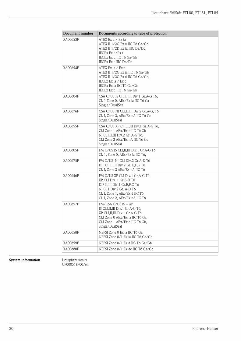
NEPSI)Document number Documents according to type of protection
XA00648F ATEX II 1G Ex ia IIC T6 Ga,
ATEX II 1/2G Ex ia IIC T6 Ga/Gb,
IECEx Ex ia IIC T6 Ga,
IECEx Ex ia IIC T6 Ga/Gb,
ATEX/IECEx Ex ia
ATEX II 1/2G Ex ia IIC T6 Ga/Gb
IECEx Ex ia IIC T6 Ga/Gb
XA00649F ATEX II 1/2G Ex d IIC T6 Ga/Gb,
IECEx Ex d IIC T6 Ga/Gb,
ATEX/IECEx Ex d
ATEX II 1/2G Ex d IIC T6 Ga/Gb
IECEx Ex d IIC T6 Ga/Gb
XA00650F ATEX II 1/2G Ex de IIC T6 Ga/Gb,
IECEx Ex de IIC T6 Ga/Gb
XA00651F ATEX II 1/3G Ex nA IIC T6 Ga/Gc,
IECEx Ex nA IIC T6 Ga/Gc
XA00652F ATEX Ex ia G/D
ATEX II 1/2G Ex ia IIC T6 Ga/Gb
ATEX II 1/2D Ex ia IIIC Da/Db,
IECEx Ex ia G/D
IECEx Ex ia IIC T6 Ga/Gb
IECEx Ex ia IIIC Da/Db
Liquiphant FailSafe FTL80, FTL81, FTL85
30 Endress+Hauser
System information Liquiphant family
CP00051F/00/en
XA00653F ATEX Ex d / Ex ta
ATEX II 1/2G Ex d IIC T6 Ga/Gb
ATEX II 1/2D Ex ta IIIC Da/Db,
IECEx Ex d/Ex t
IECEx Ex d IIC T6 Ga/Gb
IECEx Ex t IIIC Da/Db
XA00654F ATEX Ex ia / Ex d
ATEX II 1/2G Ex ia IIC T6 Ga/Gb
ATEX II 1/2G Ex d IIC T6 Ga/Gb,
IECEx Ex ia / Ex d
IECEx Ex ia IIC T6 Ga/Gb
IECEx Ex d IIC T6 Ga/Gb
XA00604F CSA C/US IS Cl I,II,III Div.1 Gr.A-G T6,
Cl. 1 Zone 0, AEx/Ex ia IIC T6 Ga
Single/DualSeal
XA00676F CSA C/US NI Cl.I,II,III Div.2 Gr.A-G, T6
Cl. I, Zone 2, AEx/Ex nA IIC T6 Gc
Single/DualSeal
XA00655F CSA C/US XP Cl.I,II,III Div.1 Gr.A-G T6,
Cl.I Zone 1 AEx/Ex d IIC T6 Gb
NI Cl.I,II,III Div.2 Gr. A-G T6,
Cl.I Zone 2 AEx/Ex nA IIC T6 Gc
Single/DualSeal
XA00605F FM C/US IS Cl.I,II,III Div.1 Gr.A-G T6
Cl. 1, Zone 0, AEx/Ex ia IIC T6,
XA00675F FM C/US NI Cl.I Div.2 Gr.A-D T6
DIP Cl. II,III Div.2 Gr. E,F,G T6
Cl. I, Zone 2 AEx/Ex nA IIC T6
XA00656F FM C/US XP Cl.I Div.1 Gr.A-G T6
XP Cl.I Div. 1 Gr.B-D T6
DIP II,III Div.1 Gr.E,F,G T6
NI Cl.1 Div.2 Gr. A-D T6
Cl. I, Zone 1, AEx/Ex d IIC T6
Cl. I, Zone 2, AEx/Ex nA IIC T6
XA00657F FM/CSA C/US IS + XP
IS Cl.I,II,III Div.1 Gr.A-G T6,
XP Cl.I,II,III Div.1 Gr.A-G T6,
Cl.I Zone 0 AEx/Ex ia IIC T6 Ga,
Cl.I Zone 1 AEx/Ex d IIC T6 Gb,
Single/DualSeal
XA00658F NEPSI Zone 0 Ex ia IIC T6 Ga,
NEPSI Zone 0/1 Ex ia IIC T6 Ga/Gb
XA00659F NEPSI Zone 0/1 Ex d IIC T6 Ga/Gb
XA00660F NEPSI Zone 0/1 Ex de IIC T6 Ga/Gb
Document number Documents according to type of protection

Liquiphant FailSafe FTL80, FTL81, FTL85
Endress+Hauser 31

Instruments International
Endress+Hauser
Instruments International AGKaegenstrasse 24153 ReinachSwitzerland
Tel.+41 61 715 81 00Fax+41 61 715 25 [email protected]
TI01026F/00/EN/02.13
71221049
FM 9 71221049