Technical Handbook - Thermal Insulation Fixings – Roofs · THERMAL INSULATION FIXINGS fi ROOFS LA...
34
THERMAL INSULATION FIXINGS – ROOFS 375 General information for correct design, installation and use of roofing insulation systems 376 GOK + WO Telescopic fixing for flat roof fastening. Max steel thickness 0.90 mm. 384 GOK + WX Telescopic fixing for flat roof fastening. Steel thickness 0.90 mm to 2×1.25 mm. 387 GOK + WBT Telescopic fixing for flat roof fastening. Anchorage in concrete. 390 GOK + WW Telescopic fixing for flat roof fastening. Anchoring in timber. 393 POW-05 + WB Aluminium washers for flat roof fastening in trapezoidal steel sheet. 396 POW-07 + WBT, WCS Aluminium washers for flat roof fastening. Anchorage in concrete. 399 POW-07, POK-041+ WW Aluminium washers for flat roof fastening. Timber construction. 404
Transcript of Technical Handbook - Thermal Insulation Fixings – Roofs · THERMAL INSULATION FIXINGS fi ROOFS LA...
THERMAL INSULATION FIXINGS – ROOFS
LA CHEVILLENYLON MULTIFONCTIONS
375
G
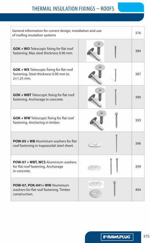
General information for correct design, installation and use of roofing insulation systems 376
GOK + WO Telescopic fixing for flat roof fastening. Max steel thickness 0.90 mm. 384
GOK + WX Telescopic fixing for flat roof fastening. Steel thickness 0.90 mm to 2×1.25 mm.
387
GOK + WBT Telescopic fixing for flat roof fastening. Anchorage in concrete. 390
GOK + WW Telescopic fixing for flat roof fastening. Anchoring in timber. 393
POW-05 + WB Aluminium washers for flat roof fastening in trapezoidal steel sheet. 396
POW-07 + WBT, WCS Aluminium washers for flat roof fastening. Anchorage in concrete.
399
POW-07, POK-041+ WW Aluminium washers for flat roof fastening. Timber construction.
404
THERMAL INSULATION FIXINGS – ROOFS
LA CHEVILLENYLON MULTIFONCTIONS
AA376
GCALCULATION OF LOADS ACTING ON ROOF
Calculation of loads acting on a roof should be conducted according to the relevant up-to-date stan-dards. In case of flat roofs, loads from wind and snow in particular need to be examined closely. (Although for thermal insulation roofing fixings any loads from snow action do not have a direct influence.) For pro-per selection of these fixings precise evaluation of wind suction loads acting on individual elements of the roof is necessary. For such purposes, information included in EN 1991-1-4 “Actions on structures – Part 1-4: General actions – Wind actions”, as well as in national annexes, are obligatory.
The national annexes of EN 1991-1-4 contain data on wind loading zones for specific countries. This information should be applied to calculations.
The major values and factors determining loads are as follows:
THERMAL AND HYDRO INSULATION FIXINGS FOR FLAT ROOFS
RAWLPLUG/KOELNER fixing systems are the most economical method for ensuring a long roofing lifes-pan with maximum reliability and security.
Roofing surfaces, especially in flat roofs, are subject to constant wind suction and shear forces, caused by the normal operation of roof elements.
Various potentially destructive influences can affect roofing, including: a) wind – so called ‘wind roll’ (suction and shear load)
b) sun – alternate heating and cooling of roofing materials (causing tensile load)c) precipitation – influence of water and snow deposits (compressive and shear load)Consequently, it is important to utilise verified, safe fixings for thermal and hydro insulation layers.RAWLPLUG/KOELNER benefit from extensive experience in ensuring safe fixing of thermal and hydro
insulation in many projects domestically and abroad. High product quality is confirmed and supported by technical approvals and certificates, permitting RAWLPLUG/KOELNER products to be used in civil engi-neering and roofing systems in which the following parameters were tested: – static values, obtained from pull out testing – anticorrosion protection in Kesternich cycles according to DIN 500 18 KFW 2.0 S – batch identification through marking on product and packaging
The guarantee provided by Allianz insurance company for all RAWLPLUG/KOELNER roofing insulation fixings acts as an indication of the confidence and trust in the products produced by our company, as well as their suitability for use in professional and responsible activity.
Proper installation of our roofing insulation fixings will provide a foundation for safe and durable func-tioning of the overall roofing system.
Realisation of a successful application can be ensured by the following actions:a) calculation of the optimum fixings quantityA deficit of fixings can be dangerous due to wind suction forces as well as the additional work demands
on roofing in changeable weather conditions. Conversely, a surplus may cause excessive perforation and, in the case of POK and POW aluminium washer solutions, extensive thermal bridging. The optimum quantity of fixings should be calculated according to wind standard EN 1991-1-4:2005 (Eurocode 1). When the calculation is not possible, the quantity can – after consultation with our technical department – be assumed, according to wind standard DIN 1055, as being:
– in corner areas – 9 pcs/m2
– in edge areas – 6 pcs/m2
– in middle area – 3 pcs/m2
b) seeking recommendations for selection of installation equipment:Please always contact our technical advisors regarding: – screwdriver coupling settings– selection of appropriate installation bits
– training in the use of appropriate installation tools by one of our technical advisors, who will pay you a visit
THERMAL INSULATION FIXINGS – ROOFS
LA CHEVILLENYLON MULTIFONCTIONS
377
G
vb = cdir . cseason . vb,0 [m/s]
The basic wind velocity:
where: Vb – basic wind velocity, defined as a function of wind direction and time of year, at 10 m above
ground of terrain category II, Vb,0 – fundamental value of the basic wind velocity (i.e. the 10 minute mean wind velocity, irrespec-
tive of wind direction and time of year, at 10 m above ground level in open country terrain with low vegetation such as grass and isolated obstacles with separation of at least 20 obstacle heights),
cdir – the directional factor (the value for various wind directions may be found in the National Annex – the recommended value is 1.0),
cseason – the season factor (the value may be given in the National Annex – the recommended value is 1.0).For permanent buildings the standard recommends to assume a value of 1 for the directional and
season factors.
The mean wind velocity at height ‘z’ above the terrain depends on the terrain roughness and orogra-phy and on the basic wind velocity. It is determined as
vm(z) = cr(z) . co(z) . vb [m/s]
Vb– the basic wind velocity [m/s], z – height above the terrain [m],
cr (z) – the roughness factor, co – the orography factor.
The roughness factor cr (z) depends on the height of the structure and terrain roughness upwind
cr(z) = kr . ln z0 for zmin ≤ z ≤zmax
cr(z) = cr(zmin) for z ≤zmin
z0 – the roughness length (Table 1),zmin – the minimum height (Table 1),zmax = 200 m,
kr – terrain factor: kr = 0.19 . zz
0
0,II 0.07
z0,II = 0.05 m,z0 – the roughness length (Table 1).
z
THERMAL INSULATION FIXINGS – ROOFS
LA CHEVILLENYLON MULTIFONCTIONS
AA378
G
1 according to EN 1991-1-4, table 4.1
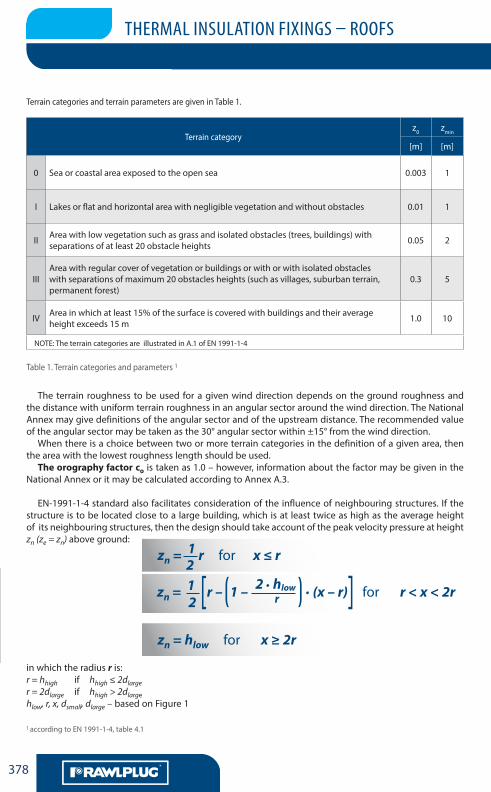
The terrain roughness to be used for a given wind direction depends on the ground roughness and the distance with uniform terrain roughness in an angular sector around the wind direction. The National Annex may give definitions of the angular sector and of the upstream distance. The recommended value of the angular sector may be taken as the 30° angular sector within ±15° from the wind direction.
When there is a choice between two or more terrain categories in the definition of a given area, then the area with the lowest roughness length should be used.
The orography factor co is taken as 1.0 – however, information about the factor may be given in the National Annex or it may be calculated according to Annex A.3.
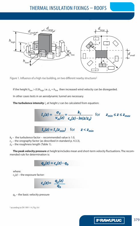
EN-1991-1-4 standard also facilitates consideration of the influence of neighbouring structures. If the structure is to be located close to a large building, which is at least twice as high as the average height of its neighbouring structures, then the design should take account of the peak velocity pressure at height zn (ze = zn) above ground:
zn = 1 r for x ≤ r
zn = 1
r – 1 – 2 . hlow . (x – r) for r < x < 2r
zn = hlow for x ≥ 2r
in which the radius r is:r = hhigh if hhigh ≤ 2dlarger = 2dlarge if hhigh > 2dlargehlow, r, x, dsmall, dlarge – based on Figure 1
Terrain categoryz0 zmin
[m] [m]
0 Sea or coastal area exposed to the open sea 0.003 1
I Lakes or flat and horizontal area with negligible vegetation and without obstacles 0.01 1
II Area with low vegetation such as grass and isolated obstacles (trees, buildings) with separations of at least 20 obstacle heights 0.05 2
IIIArea with regular cover of vegetation or buildings or with or with isolated obstacles with separations of maximum 20 obstacles heights (such as villages, suburban terrain, permanent forest)
0.3 5
IV Area in which at least 15% of the surface is covered with buildings and their average height exceeds 15 m 1.0 10
NOTE: The terrain categories are illustrated in A.1 of EN 1991-1-4
Terrain categories and terrain parameters are given in Table 1.
Table 1. Terrain categories and parameters 1
2
2 r[ [
THERMAL INSULATION FIXINGS – ROOFS
LA CHEVILLENYLON MULTIFONCTIONS
r-kex
379
G
Figure 1. Influence of a high rise building, on two different nearby structures2
moindre des deux e = b ou 2hb – dimension latérale à la direction du vent
1x1
x22
dsmall
r
r
dlarge
1
2
dlargedsmall
hhigh
hlow
hlow1
hp
h
greniers
ze
bords arrondis et mansarde
bord du toit
ze=hr α
F
e/4 e/4
e/10
e/2
vent
d
b
G
H
I
F
2,0
m8,
0 m
2,0 m 8,0 m
2,0
m8,
0 m
5,0
m70
m5,
0 m
2,0 m8,0 m
5,0 m30 m5,0 m
5,0 m30 m5,0 m
40 m
5,0
m70
m
80 m
5,0
m
If the height hlow > 0.5hhigh i.e. zn = hlow then increased wind velocity can be disregarded.
In other cases tests in an aerodynamic tunnel are necessary.
The turbulence intensity Iv at height z can be calculated from equation:
Iv(z) = σv = kI for zmin ≤ z ≤ zmax
Iv(z) = Iv(zmin) for z < zmin
kI – the turbulence factor – recommended value is 1.0,co – the orography factor (as described in standard p. 4.3.3),z0 – the roughness length (Table 1).
The peak velocity pressure at height z includes mean and short-term velocity fluctuations. The recom-mended rule for determination is:
qp(z) = ce(z) . qb
where: ce(z) – the exposure factor:
ce(z)=
qb – the basic velocity pressure
vm(z) co(z) . ln(z/z0)
qp(z)qb
2 according to EN 1991-1-4, Fig. A.4
LA CHEVILLENYLON MULTIFONCTIONS
THERMAL INSULATION FIXINGS – ROOFS
LA CHEVILLENYLON MULTIFONCTIONS
AA380
G
During determination of qp calculations between different terrain roughness categories should be taken into account – if a structure with height h is situated closer than 30h from the beginning of a lower terrain category (than the one which directly surrounds the structure), then it should be assumed that structure sits within the lower terrain category.
The basic velocity pressure is calculated:
qb = 1 . ρ . vb2
ρ – air density
Wind actions on structures and structural elements shall be determined taking account of both exter-nal and internal wind pressures.
For walls and roofs with an impermeable outside skin and an impermeable, more rigid inside skin, the wind force on the outside skin may be calculated from cp,net = cpe (p.7.2.10 EN 1991-1-4).
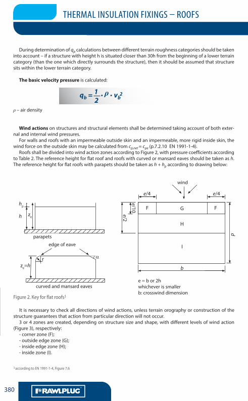
Roofs shall be divided into wind action zones according to Figure 2, with pressure coefficients according to Table 2. The reference height for flat roof and roofs with curved or mansard eaves should be taken as h. The reference height for flat roofs with parapets should be taken as h + hp according to drawing below:
moindre des deux e = b ou 2hb – dimension latérale à la direction du vent
1x1
x22
dsmall
r
r
dlarge
1
2
dlargedsmall
hhigh
hlow
hlow1
hp
h
greniers
ze
bords arrondis et mansarde
bord du toit
ze=hr α
F
e/4 e/4
e/10
e/2
vent
d
b
G
H
I
F
2,0
m8,
0 m
2,0 m 8,0 m
2,0
m8,
0 m
5,0
m70
m5,
0 m
2,0 m8,0 m
5,0 m30 m5,0 m
5,0 m30 m5,0 m
40 m
5,0
m70
m
80 m
5,0
m
parapets
edge of eave
wind
e = b or 2h whichever is smallerb: crosswind dimension
curved and mansard eaves
Figure 2. Key for flat roofs3
It is necessary to check all directions of wind actions, unless terrain orography or construction of the structure guarantees that action from particular direction will not occur.
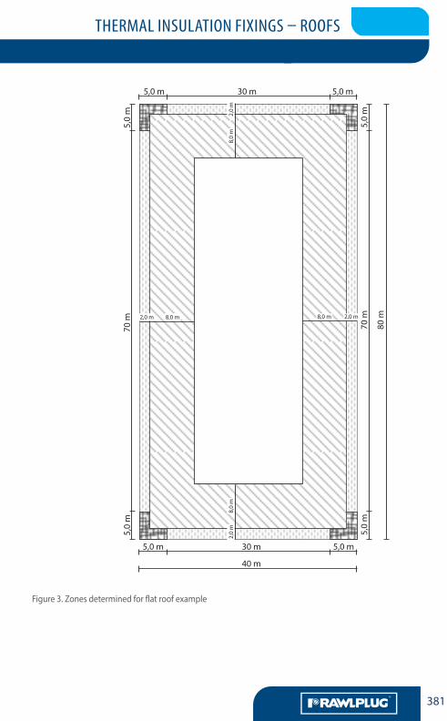
3 or 4 zones are created, depending on structure size and shape, with different levels of wind action (Figure 3), respectively:
- corner zone (F);- outside edge zone (G);- inside edge zone (H);- inside zone (I).
3 according to EN 1991-1-4, Figure 7.6
2
THERMAL INSULATION FIXINGS – ROOFS
LA CHEVILLENYLON MULTIFONCTIONS
r-kex
381
G
moindre des deux e = b ou 2hb – dimension latérale à la direction du vent
1x1
x22
dsmall
r
r
dlarge
1
2
dlargedsmall
hhigh
hlow
hlow1
hp
h
greniers
ze
bords arrondis et mansarde
bord du toit
ze=hr α
F
e/4 e/4
e/10
e/2
vent
d
b
G
H
I
F
2,0
m8,
0 m
2,0 m 8,0 m
2,0
m8,
0 m
5,0
m70
m5,
0 m
2,0 m8,0 m
5,0 m30 m5,0 m
5,0 m30 m5,0 m
40 m
5,0
m70
m
80 m
5,0
m
Figure 3. Zones determined for flat roof example
LA CHEVILLENYLON MULTIFONCTIONS
THERMAL INSULATION FIXINGS – ROOFS
LA CHEVILLENYLON MULTIFONCTIONS
AA382
G
4 according to EN 1991-1-4, table 7.2
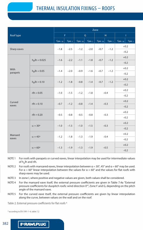
Roof type
Zone
F G H I
cpe, 10 cpe, 1 cpe, 10 cpe, 1 cpe, 10 cpe, 1 cpe, 10 cpe, 1
Sharp eaves –1.8 –2.5 –1.2 –2.0 –0.7 –1.2+0.2
–0.2
Withparapets
hplh = 0.025 –1.6 –2.2 –1.1 –1.8 –0.7 –1.2+0.2
–0.2
hplh = 0.05 –1.4 –2.0 –0.9 –1.6 –0.7 –1.2+0.2
–0.2
hplh = 0.10 –1.2 –1.8 –0.8 –1.4 –0.7 –1.2+0.2
–0.2
Curved eaves
rlh = 0.05 –1.0 –1.5 –1.2 –1.8 –0.4+0.2
–0.2
rlh = 0.10 –0.7 –1.2 –0.8 –1.4 –0.3+0.2
–0.2
rlh = 0.20 –0.5 –0.8 –0.5 –0.8 –0.3+0.2
–0.2
Mansardeaves
α = 30o –1.0 –1.5 –1.0 –1.5 –0.3+0.2
–0.2
α = 45o –1.2 –1.8 –1.3 –1.9 –0.4+0.2
–0.2
α = 60o –1.3 –1.9 –1.3 –1.9 –0.5+0.2
–0.2
NOTE 1 For roofs with parapets or curved eaves, linear interpolation may be used for intermediate values of hplh and rlh.
NOTE 2 For roofs with mansared eaves, linear interpolation between α = 30°, 45° and α = 60° may be used. For α > 60° linear interpolation between the values for α = 60° and the values for flat roofs with sharp eaves may be used.
NOTE 3 In zone I, where positive and negative values are given, both values shall be considered.
NOTE 4 For the mansard eave itself, the external pressure coefficients are given in Table 7.4a ”External pressure coefficients for duopitch roofs: wind direction 0°”, Zone F and G, depending on the pitch angle of the mansard eave.
NOTE 5 For the curved eave itself, the external pressure coefficients are given by linear interpolation along the curve, between values on the wall and on the roof.
Table 2. External pressure coefficients for flat roofs 4
THERMAL INSULATION FIXINGS – ROOFS
LA CHEVILLENYLON MULTIFONCTIONS
r-kex
383
G
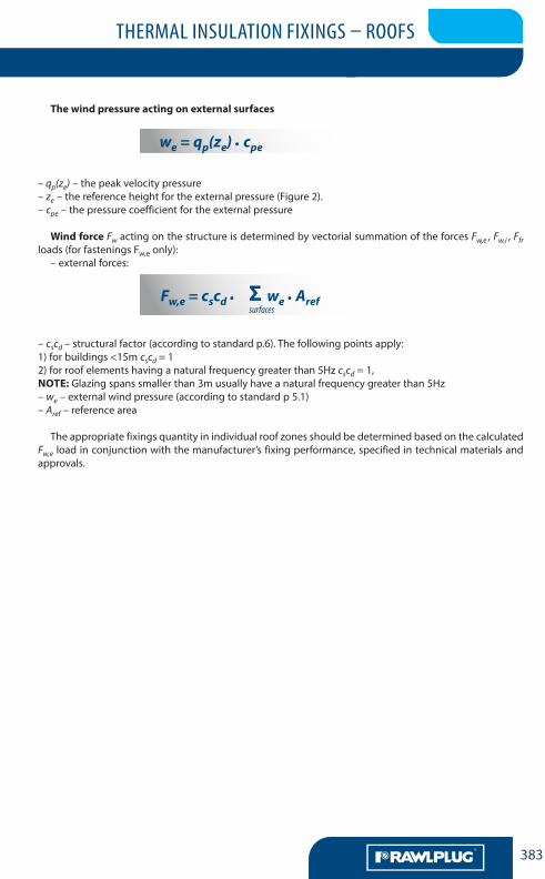
The wind pressure acting on external surfaces
we = qp(ze) . cpe
– qp(ze) – the peak velocity pressure– ze – the reference height for the external pressure (Figure 2).– cpe – the pressure coefficient for the external pressure
Wind force Fw acting on the structure is determined by vectorial summation of the forces Fw,e , Fw,i , Ffr loads (for fastenings Fw,e only):
– external forces:
Fw,e = cscd . we . Aref
– cscd – structural factor (according to standard p.6). The following points apply:1) for buildings <15m cscd = 12) for roof elements having a natural frequency greater than 5Hz cscd = 1,NOTE: Glazing spans smaller than 3m usually have a natural frequency greater than 5Hz– we – external wind pressure (according to standard p 5.1)– Aref – reference area
The appropriate fixings quantity in individual roof zones should be determined based on the calculated Fw,e load in conjunction with the manufacturer’s fixing performance, specified in technical materials and approvals.
Σsurfaces
LA CHEVILLENYLON MULTIFONCTIONS
THERMAL INSULATION FIXINGS – ROOFS
LA CHEVILLENYLON MULTIFONCTIONS
AA384
G
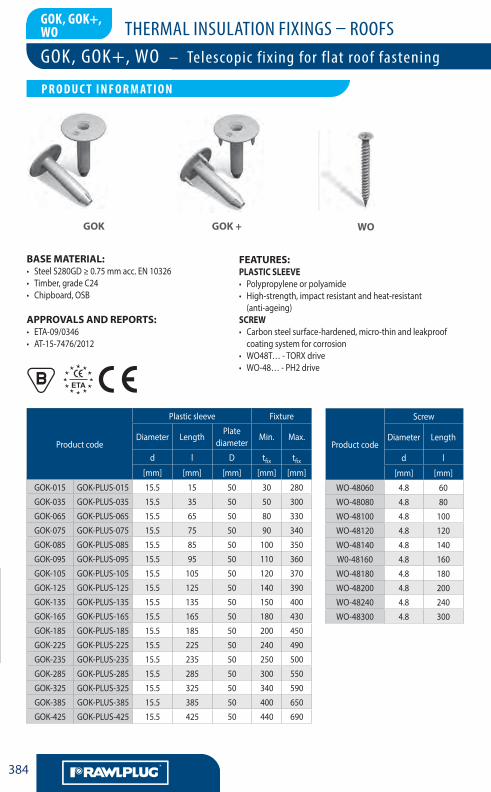
GOK, GOK+,WO
BASE MATERIAL:• Steel S280GD ≥ 0.75 mm acc. EN 10326• Timber, grade C24• Chipboard, OSB
APPROVALS AND REPORTS:• ETA-09/0346 • AT-15-7476/2012
Product code
Plastic sleeve Fixture
Diameter LengthPlate
diameterMin. Max.
d l D tfix tfix
[mm] [mm] [mm] [mm] [mm]
GOK-015 GOK-PLUS-015 15.5 15 50 30 280
GOK-035 GOK-PLUS-035 15.5 35 50 50 300
GOK-065 GOK-PLUS-065 15.5 65 50 80 330
GOK-075 GOK-PLUS-075 15.5 75 50 90 340
GOK-085 GOK-PLUS-085 15.5 85 50 100 350
GOK-095 GOK-PLUS-095 15.5 95 50 110 360
GOK-105 GOK-PLUS-105 15.5 105 50 120 370
GOK-125 GOK-PLUS-125 15.5 125 50 140 390
GOK-135 GOK-PLUS-135 15.5 135 50 150 400
GOK-165 GOK-PLUS-165 15.5 165 50 180 430
GOK-185 GOK-PLUS-185 15.5 185 50 200 450
GOK-225 GOK-PLUS-225 15.5 225 50 240 490
GOK-235 GOK-PLUS-235 15.5 235 50 250 500
GOK-285 GOK-PLUS-285 15.5 285 50 300 550
GOK-325 GOK-PLUS-325 15.5 325 50 340 590
GOK-385 GOK-PLUS-385 15.5 385 50 400 650
GOK-425 GOK-PLUS-425 15.5 425 50 440 690
Product code
Screw
Diameter Length
d l
[mm] [mm]
WO-48060 4.8 60
WO-48080 4.8 80
WO-48100 4.8 100
WO-48120 4.8 120
WO-48140 4.8 140
W0-48160 4.8 160
WO-48180 4.8 180
WO-48200 4.8 200
WO-48240 4.8 240
WO-48300 4.8 300
FEATURES:PLASTIC SLEEVE• Polypropylene or polyamide • High-strength, impact resistant and heat-resistant
(anti-ageing)SCREW• Carbon steel surface-hardened, micro-thin and leakproof
coating system for corrosion• WO48T… - TORX drive• WO-48… - PH2 drive
GOK WOGOK +
GOK, GOK+, WO – Telescopic fixing for flat roof fastening
LA CHEVILLENYLON MULTIFONCTIONS
P R O D U C T I N F O R M AT I O N
THERMAL INSULATION FIXINGS – ROOFS
LA CHEVILLENYLON MULTIFONCTIONS
385
G
GOK, GOK+, WO
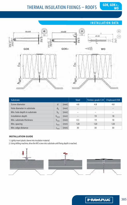
Substrate Steel Timber, grade C24 Chipboard OSB
Screw diameter d [mm] 4.8 4.8 4.8
Hole diameter in substrate d0 [mm] – − −
Min. hole depth in substrate h0 [mm] – − −
Installation depth hnom [mm] – 19 18
Min. substrate thickness hmin [mm] 0.5 19 18
Min. spacing smin [mm] 120 120 120
Min. edge distance cmin [mm] 30 30 30
WO
1. Lightly insert plastic sleeve into insulation material.2. Using drilling machine, drive the WO screw into substrate until fixing depth is reached.
INSTALLATION GUIDE
GOK GOK+
LA CHEVILLENYLON MULTIFONCTIONS
I N S TA L L AT I O N DATA
THERMAL INSULATION FIXINGS – ROOFS
LA CHEVILLENYLON MULTIFONCTIONS
AA386
G
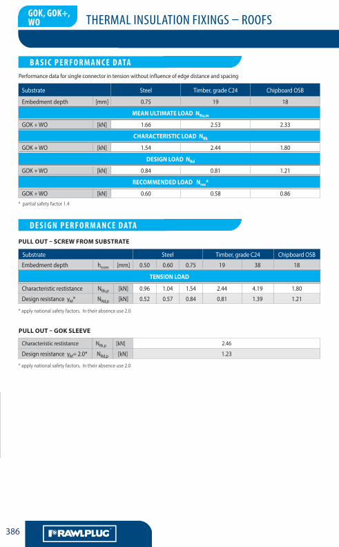
* partial safety factor 1.4
* apply national safety factors. In their absence use 2.0
* apply national safety factors. In their absence use 2.0
Substrate Steel Timber, grade C24 Chipboard OSB
Embedment depth [mm] 0.75 19 18
Mean ultiMate load nRu,m
GOK + WO [kN] 1.66 2.53 2.33
ChaRaCteRistiC load nRk
GOK + WO [kN] 1.54 2.44 1.80
design load nRd
GOK + WO [kN] 0.84 0.81 1.21
ReCoMMended load nrec*
GOK + WO [kN] 0.60 0.58 0.86
Substrate Steel Timber, grade C24 Chipboard OSB
Embedment depth hnom [mm] 0.50 0.60 0.75 19 38 18
tension load
Characteristic restistance NRk,p [kN] 0.96 1.04 1.54 2.44 4.19 1.80
Design resistance γM* NRd,p [kN] 0.52 0.57 0.84 0.81 1.39 1.21
Characteristic restistance NRk,p [kN] 2.46
Design resistance γM= 2.0* NRd,p [kN] 1.23
Pull out – goK sleeVe
Pull out – sCReW FRoM suBstRate
LA CHEVILLENYLON MULTIFONCTIONS
B A S I C P E R F O R M A N C E DATA
LA CHEVILLENYLON MULTIFONCTIONS
D E S I G N P E R F O R M A N C E DATA
GOK, GOK+, WO
Performance data for single connector in tension without influence of edge distance and spacing
THERMAL INSULATION FIXINGS – ROOFS
LA CHEVILLENYLON MULTIFONCTIONS
387
G
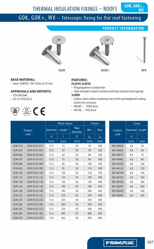
Base MateRial:• Steel S280GD - EN 10326 ≥0.75 mm
aPPRoVals and RePoRts:• ETA-09/0346 • AT-15-7476/2012
Product code
Plastic sleeve Fixture
Diameter LengthPlate
diameterMin. Max.
d l D tfix tfix
[mm] [mm] [mm] [mm] [mm]
GOK-015 GOK-PLUS-015 15.5 15 50 30 280
GOK-035 GOK-PLUS-035 15.5 35 50 50 300
GOK-065 GOK-PLUS-065 15.5 65 50 80 330
GOK-075 GOK-PLUS-075 15.5 75 50 90 340
GOK-085 GOK-PLUS-085 15.5 85 50 100 350
GOK-095 GOK-PLUS-095 15.5 95 50 110 360
GOK-105 GOK-PLUS-105 15.5 105 50 120 370
GOK-125 GOK-PLUS-125 15.5 125 50 140 390
GOK-135 GOK-PLUS-135 15.5 135 50 150 400
GOK-165 GOK-PLUS-165 15.5 165 50 180 430
GOK-185 GOK-PLUS-185 15.5 185 50 200 450
GOK-225 GOK-PLUS-225 15.5 225 50 240 490
GOK-235 GOK-PLUS-235 15.5 235 50 250 500
GOK-285 GOK-PLUS-285 15.5 285 50 300 550
GOK-325 GOK-PLUS-325 15.5 325 50 340 590
GOK-385 GOK-PLUS-385 15.5 385 50 400 650
GOK-425 GOK-PLUS-425 15.5 425 50 440 690
Product code
Screw
Diameter Length
d l
[mm] [mm]
WX-48050 4.8 50
WX-48060 4.8 60
WX-48070 4.8 70
WX-48080 4.8 80
WX-48100 4.8 100
WX-48120 4.8 120
WX-48140 4.8 140
WX-48160 4.8 160
WX-48180 4.8 180
WX-48200 4.8 200
WX-48240 4.8 240
WX-48300 4.8 300
FeatuRes:PlastiC sleeVe• Polypropylene or polyamide • High-strength, impact resistant and heat-resistant (anti-ageing)sCReW• Carbon steel surface-hardened, micro-thin and leakproof coating
system for corrosion• WX48T… - TORX drive• WX-48… - PH2 drive
goK goK+ WX
GOK, GOK+, WX
LA CHEVILLENYLON MULTIFONCTIONS
P R O D U C T I N F O R M AT I O N
GOK, GOK+, WX – Telescopic fixing for flat roof fastening
THERMAL INSULATION FIXINGS – ROOFS
LA CHEVILLENYLON MULTIFONCTIONS
AA388
G
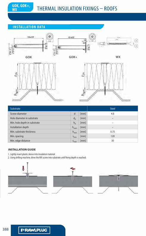
Substrate Steel
Screw diameter d [mm] 4.8
Hole diameter in substrate d0 [mm] –
Min. hole depth in substrate h0 [mm] –
Installation depth hnom [mm] –
Min. substrate thickness hmin [mm] 0.75
Min. spacing smin [mm] 120
Min. edge distance cmin [mm] 30
1. Lightly insert plastic sleeve into insulation material.2. Using drilling machine, drive the WX screw into substrate until fixing depth is reached.
installation guide
goK goK+ WX
LA CHEVILLENYLON MULTIFONCTIONS
I N S TA L L AT I O N DATA
GOK, GOK+, WX
THERMAL INSULATION FIXINGS – ROOFS
LA CHEVILLENYLON MULTIFONCTIONS
389
G
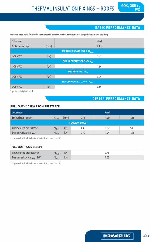
* partial safety factor 1.4
Substrate Steel
Embedment depth [mm] 0.75
Mean ultiMate load nRu,m
GOK +WX [kN] 1.42
ChaRaCteRistiC load nRk
GOK +WX [kN] 1.30
design load nRd
GOK +WX [kN] 0.70
ReCoMMended load nrec*
GOK +WX [kN] 0.50
Substrate Steel
Embedment depth hnom [mm] 0.75 1.00 1.25
tension load
Characteristic restistance NRk,p [kN] 1.30 1.92 2.48
Design resistance γM* NRd,p [kN] 0.70 1.04 1.35
Characteristic restistance NRk,p [kN] 2.46
Design resistance γM= 2.0* NRd,p [kN] 1.23
Pull out – goK sleeVe
* apply national safety factors. In their absence use 2.0
* apply national safety factors. In their absence use 2.0
Pull out – sCReW FRoM suBstRate
LA CHEVILLENYLON MULTIFONCTIONS
B A S I C P E R F O R M A N C E DATA
LA CHEVILLENYLON MULTIFONCTIONS
D E S I G N P E R F O R M A N C E DATA
GOK, GOK+, WX
Performance data for single connector in tension without influence of edge distance and spacing
THERMAL INSULATION FIXINGS – ROOFS
LA CHEVILLENYLON MULTIFONCTIONS
AA390
G
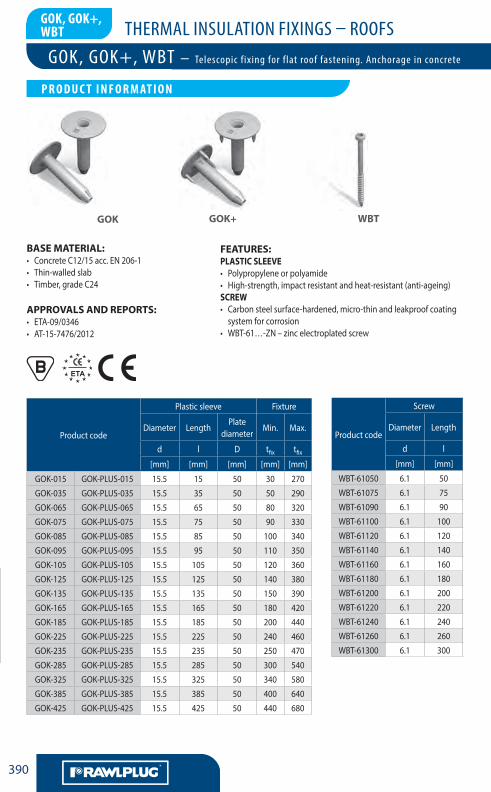
Base MateRial:• Concrete C12/15 acc. EN 206-1• Thin-walled slab• Timber, grade C24
aPPRoVals and RePoRts:• ETA-09/0346 • AT-15-7476/2012
Product code
Plastic sleeve Fixture
Diameter LengthPlate
diameterMin. Max.
d l D tfix tfix
[mm] [mm] [mm] [mm] [mm]
GOK-015 GOK-PLUS-015 15.5 15 50 30 270
GOK-035 GOK-PLUS-035 15.5 35 50 50 290
GOK-065 GOK-PLUS-065 15.5 65 50 80 320
GOK-075 GOK-PLUS-075 15.5 75 50 90 330
GOK-085 GOK-PLUS-085 15.5 85 50 100 340
GOK-095 GOK-PLUS-095 15.5 95 50 110 350
GOK-105 GOK-PLUS-105 15.5 105 50 120 360
GOK-125 GOK-PLUS-125 15.5 125 50 140 380
GOK-135 GOK-PLUS-135 15.5 135 50 150 390
GOK-165 GOK-PLUS-165 15.5 165 50 180 420
GOK-185 GOK-PLUS-185 15.5 185 50 200 440
GOK-225 GOK-PLUS-225 15.5 225 50 240 460
GOK-235 GOK-PLUS-235 15.5 235 50 250 470
GOK-285 GOK-PLUS-285 15.5 285 50 300 540
GOK-325 GOK-PLUS-325 15.5 325 50 340 580
GOK-385 GOK-PLUS-385 15.5 385 50 400 640
GOK-425 GOK-PLUS-425 15.5 425 50 440 680
Product code
Screw
Diameter Length
d l
[mm] [mm]
WBT-61050 6.1 50
WBT-61075 6.1 75
WBT-61090 6.1 90
WBT-61100 6.1 100
WBT-61120 6.1 120
WBT-61140 6.1 140
WBT-61160 6.1 160
WBT-61180 6.1 180
WBT-61200 6.1 200
WBT-61220 6.1 220
WBT-61240 6.1 240
WBT-61260 6.1 260
WBT-61300 6.1 300
FeatuRes:PlastiC sleeVe• Polypropylene or polyamide • High-strength, impact resistant and heat-resistant (anti-ageing)sCReW• Carbon steel surface-hardened, micro-thin and leakproof coating
system for corrosion• WBT-61…-ZN – zinc electroplated screw
goK WBtgoK+
GOK, GOK+, WBT
GOK, GOK+, WBT – Telescopic fixing for flat roof fastening. Anchorage in concrete
LA CHEVILLENYLON MULTIFONCTIONS
P R O D U C T I N F O R M AT I O N
THERMAL INSULATION FIXINGS – ROOFS
LA CHEVILLENYLON MULTIFONCTIONS
391
G
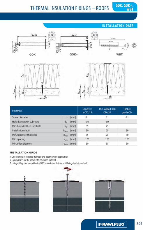
GOK, GOK+, WBT – Telescopic fixing for flat roof fastening. Anchorage in concrete
SubstrateConcrete ≥ C12/15
Thin-walled slab C16/20
Timber, grade C24
Screw diameter d [mm] 6.1 6.1 6.1
Hole diameter in substrate d0 [mm] 5.0 5.0 -
Min. hole depth in substrate h0 [mm] 35 25 -
Installation depth hnom [mm] 30 20 30
Min. substrate thickness hmin [mm] 35 20 30
Min. spacing smin [mm] 120 120 120
Min. edge distance cmin [mm] 30 30 50
installation guide
WBtgoK goK+
1. Drill the hole of required diameter and depth (where applicable).2. Lightly insert plastic sleeve into insulation material.3. Using drilling machine, drive the WBT screw into substrate until fixing depth is reached.
LA CHEVILLENYLON MULTIFONCTIONS
I N S TA L L AT I O N DATA
GOK, GOK+, WBT
THERMAL INSULATION FIXINGS – ROOFS
LA CHEVILLENYLON MULTIFONCTIONS
AA392
G
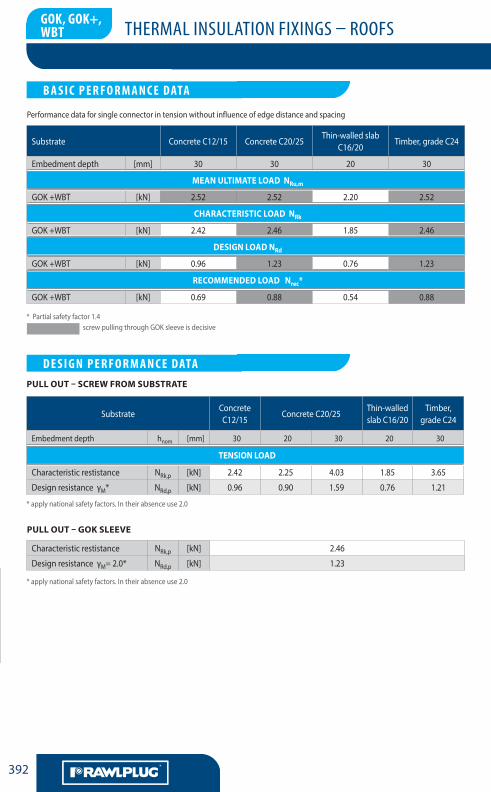
* Partial safety factor 1.4
* apply national safety factors. In their absence use 2.0
screw pulling through GOK sleeve is decisive
Substrate Concrete C12/15 Concrete C20/25Thin-walled slab
C16/20Timber, grade C24
Embedment depth [mm] 30 30 20 30
Mean ultiMate load nRu,m
GOK +WBT [kN] 2.52 2.52 2.20 2.52
ChaRaCteRistiC load nRk
GOK +WBT [kN] 2.42 2.46 1.85 2.46
design load nRd
GOK +WBT [kN] 0.96 1.23 0.76 1.23
ReCoMMended load nrec*
GOK +WBT [kN] 0.69 0.88 0.54 0.88
SubstrateConcrete C12/15
Concrete C20/25Thin-walled slab C16/20
Timber, grade C24
Embedment depth hnom [mm] 30 20 30 20 30
tension load
Characteristic restistance NRk,p [kN] 2.42 2.25 4.03 1.85 3.65
Design resistance γM* NRd,p [kN] 0.96 0.90 1.59 0.76 1.21
Characteristic restistance NRk,p [kN] 2.46
Design resistance γM= 2.0* NRd,p [kN] 1.23
Pull out – goK sleeVe
* apply national safety factors. In their absence use 2.0
Pull out – sCReW FRoM suBstRate
GOK, GOK+, WBT
LA CHEVILLENYLON MULTIFONCTIONS
B A S I C P E R F O R M A N C E DATA
LA CHEVILLENYLON MULTIFONCTIONS
D E S I G N P E R F O R M A N C E DATA
Performance data for single connector in tension without influence of edge distance and spacing
THERMAL INSULATION FIXINGS – ROOFS
LA CHEVILLENYLON MULTIFONCTIONS
393
G
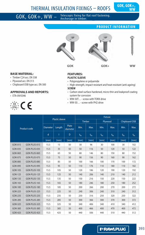
Base MateRial:• Timber C24 acc. EN 338• Plywood acc. EN 313• Chipboard OSB type acc. EN 300
aPPRoVals and RePoRts:• ETA-09/0346
Product code
Plastic sleeveFixture
Timber Plywood Chipboard OSB
Diameter LengthPlate
diameterMin. Max. Min. Max. Min. Max.
d l D tfix tfix tfix tfix tfix tfix
[mm] [mm] [mm] [mm] [mm] [mm] [mm] [mm] [mm]
GOK-015 GOK-PLUS-015 15.5 15 50 30 96 30 100 30 102
GOK-035 GOK-PLUS-035 15.5 35 50 50 116 50 120 50 122
GOK-065 GOK-PLUS-065 15.5 65 50 80 146 80 150 80 152
GOK-075 GOK-PLUS-075 15.5 75 50 90 156 90 160 90 162
GOK-085 GOK-PLUS-085 15.5 85 50 100 166 100 170 100 172
GOK-095 GOK-PLUS-095 15.5 95 50 110 176 110 180 110 182
GOK-105 GOK-PLUS-105 15.5 105 50 120 186 120 190 120 192
GOK-125 GOK-PLUS-125 15.5 125 50 140 206 140 210 140 212
GOK-135 GOK-PLUS-135 15.5 135 50 150 216 150 220 150 222
GOK-165 GOK-PLUS-165 15.5 165 50 180 246 180 250 180 252
GOK-185 GOK-PLUS-185 15.5 185 50 200 266 200 270 200 272
GOK-225 GOK-PLUS-225 15.5 225 50 240 306 240 310 240 312
GOK-235 GOK-PLUS-235 15.5 235 50 250 316 250 320 250 322
GOK-285 GOK-PLUS-285 15.5 285 50 300 366 300 370 300 372
GOK-325 GOK-PLUS-325 15.5 325 50 340 406 340 410 340 412
GOK-385 GOK-PLUS-385 15.5 385 50 400 466 400 470 400 472
GOK-425 GOK-PLUS-425 15.5 425 50 440 506 440 510 440 512
FeatuRes:PlastiC sleeVe• Polypropylene or polyamide• High-strength, impact resistant and heat-resistant (anti-ageing)sCReW• Carbon steel surface-hardened, micro-thin and leakproof coating
system for corrosion• WW-50T… - screw with TORX drive• WW-50… - screw with PH2 drive
goK goK+ WW
GOK, GOK+, WW
LA CHEVILLENYLON MULTIFONCTIONS
P R O D U C T I N F O R M AT I O N
GOK, GOK+, WW – Telescopic fixing for flat roof fastening. Anchorage in timber.
THERMAL INSULATION FIXINGS – ROOFS
LA CHEVILLENYLON MULTIFONCTIONS
AA394
G
Product code
Screw
Diameter Length
d l
[mm] [mm]
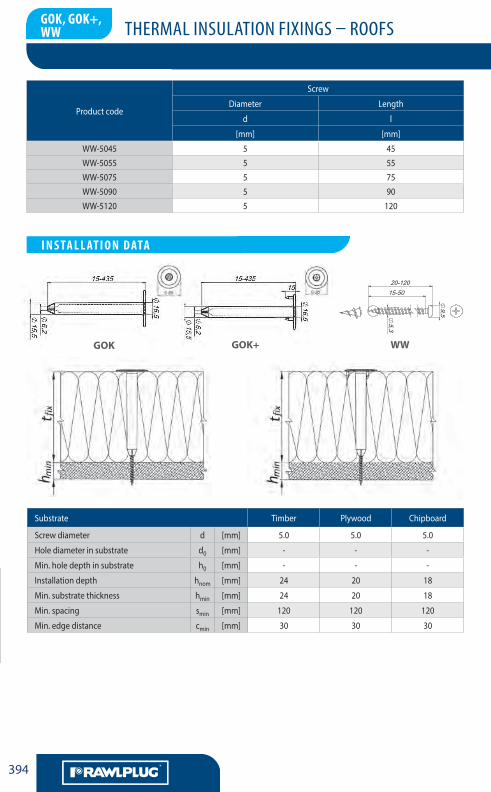
WW-5045 5 45
WW-5055 5 55
WW-5075 5 75
WW-5090 5 90
WW-5120 5 120
Substrate Timber Plywood Chipboard
Screw diameter d [mm] 5.0 5.0 5.0
Hole diameter in substrate d0 [mm] - - -
Min. hole depth in substrate h0 [mm] - - -
Installation depth hnom [mm] 24 20 18
Min. substrate thickness hmin [mm] 24 20 18
Min. spacing smin [mm] 120 120 120
Min. edge distance cmin [mm] 30 30 30
goK goK+ WW
LA CHEVILLENYLON MULTIFONCTIONS
I N S TA L L AT I O N DATA
GOK, GOK+, WW
THERMAL INSULATION FIXINGS – ROOFS
LA CHEVILLENYLON MULTIFONCTIONS
395
G
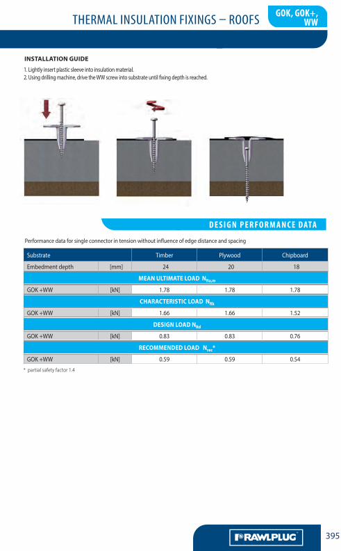
installation guide
* partial safety factor 1.4
Substrate Timber Plywood Chipboard
Embedment depth [mm] 24 20 18
Mean ultiMate load nRu,m
GOK +WW [kN] 1.78 1.78 1.78
ChaRaCteRistiC load nRk
GOK +WW [kN] 1.66 1.66 1.52
design load nRd
GOK +WW [kN] 0.83 0.83 0.76
ReCoMMended load nrec*
GOK +WW [kN] 0.59 0.59 0.54
1. Lightly insert plastic sleeve into insulation material.2. Using drilling machine, drive the WW screw into substrate until fixing depth is reached.
LA CHEVILLENYLON MULTIFONCTIONS
D E S I G N P E R F O R M A N C E DATA
GOK, GOK+,WW
Performance data for single connector in tension without influence of edge distance and spacing
THERMAL INSULATION FIXINGS – ROOFS
LA CHEVILLENYLON MULTIFONCTIONS
AA396
G
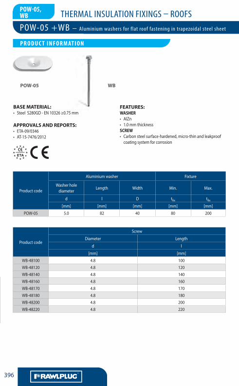
BASE MATERIAL:• SteelS280GD-EN10326≥0.75mm
APPROVALS AND REPORTS:• ETA-09/0346• AT-15-7476/2012
Productcode
Aluminiumwasher Fixture
Washerholediameter
Length Width Min. Max.
d l D tfix tfix[mm] [mm] [mm] [mm] [mm]
POW-05 5.0 82 40 80 200
Productcode
Screw
Diameter Length
d l
[mm] [mm]
WB-48100 4.8 100
WB-48120 4.8 120
WB-48140 4.8 140
WB-48160 4.8 160
WB-48170 4.8 170
WB-48180 4.8 180
WB-48200 4.8 200
WB-48220 4.8 220
FEATURES:WASHER• AlZn• 1.0mmthicknessSCREW• Carbonsteelsurface-hardened,micro-thinandleakproofcoatingsystemforcorrosion
POW-05 WB
POW-05,WB
POW-05 +WB – Aluminium washers for flat roof fastening in trapezoidal steel sheet
LA CHEVILLENYLON MULTIFONCTIONS
P R O D U C T I N F O R M AT I O N
THERMAL INSULATION FIXINGS – ROOFS
LA CHEVILLENYLON MULTIFONCTIONS
397
G
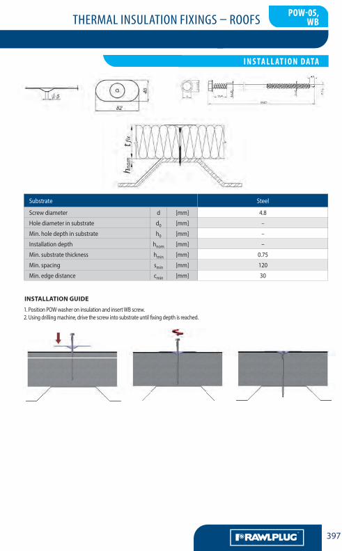
Substrate Steel
Screwdiameter d [mm] 4.8
Holediameterinsubstrate d0 [mm] –
Min.holedepthinsubstrate h0 [mm] –
Installationdepth hnom [mm] –
Min.substratethickness hmin [mm] 0.75
Min.spacing smin [mm] 120
Min.edgedistance cmin [mm] 30
1.PositionPOWwasheroninsulationandinsertWBscrew.2.Usingdrillingmachine,drivethescrewintosubstrateuntilfixingdepthisreached.
INSTALLATION GUIDE
POW-05,WB
LA CHEVILLENYLON MULTIFONCTIONS
I N S TA L L AT I O N DATA
THERMAL INSULATION FIXINGS – ROOFS
LA CHEVILLENYLON MULTIFONCTIONS
AA398
G
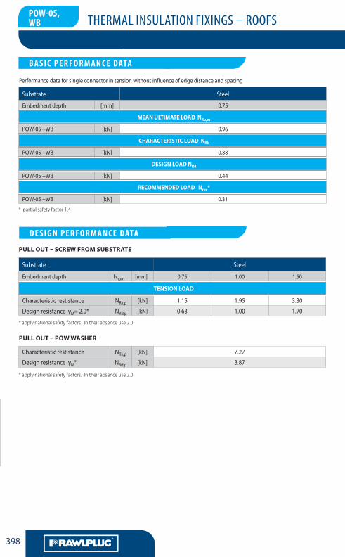
*partialsafetyfactor1.4
Substrate Steel
Embedmentdepth [mm] 0.75
MEAN ULTIMATE LOAD NRu,m
POW-05+WB [kN] 0.96
CHARACTERISTIC LOAD NRk
POW-05+WB [kN] 0.88
DESIGN LOAD NRd
POW-05+WB [kN] 0.44
RECOMMENDED LOAD Nrec*
POW-05+WB [kN] 0.31
Substrate Steel
Embedmentdepth hnom [mm] 0.75 1.00 1.50
TENSION LOAD
Characteristicrestistance NRk,p [kN] 1.15 1.95 3.30
DesignresistanceγM=2.0* NRd,p [kN] 0.63 1.00 1.70
Characteristicrestistance NRk,p [kN] 7.27
DesignresistanceγM* NRd,p [kN] 3.87
PULL OUT – POW WASHER
*applynationalsafetyfactors.Intheirabsenceuse2.0
*applynationalsafetyfactors.Intheirabsenceuse2.0
PULL OUT – SCREW FROM SUBSTRATE
LA CHEVILLENYLON MULTIFONCTIONS
B A S I C P E R F O R M A N C E DATA
LA CHEVILLENYLON MULTIFONCTIONS
D E S I G N P E R F O R M A N C E DATA
POW-05,WB
Performancedataforsingleconnectorintensionwithoutinfluenceofedgedistanceandspacing
THERMAL INSULATION FIXINGS – ROOFS
LA CHEVILLENYLON MULTIFONCTIONS
399
G
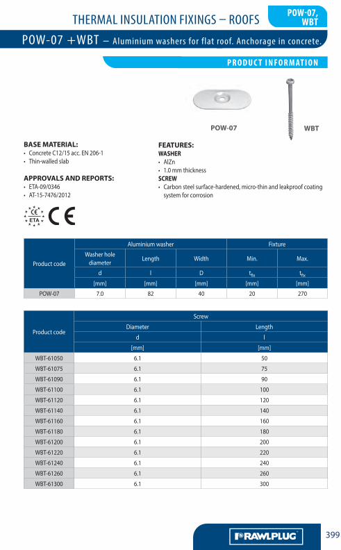
BASE MATERIAL:• ConcreteC12/15acc.EN206-1• Thin-walledslab
APPROVALS AND REPORTS:• ETA-09/0346• AT-15-7476/2012
FEATURES:WASHER• AlZn• 1.0mmthicknessSCREW• Carbonsteelsurface-hardened,micro-thinandleakproofcoatingsystemforcorrosion
POW-07 WBT
Productcode
Screw
Diameter Length
d l
[mm] [mm]
WBT-61050 6.1 50
WBT-61075 6.1 75
WBT-61090 6.1 90
WBT-61100 6.1 100
WBT-61120 6.1 120
WBT-61140 6.1 140
WBT-61160 6.1 160
WBT-61180 6.1 180
WBT-61200 6.1 200
WBT-61220 6.1 220
WBT-61240 6.1 240
WBT-61260 6.1 260
WBT-61300 6.1 300
Productcode
Aluminiumwasher Fixture
Washerholediameter
Length Width Min. Max.
d l D tfix tfix[mm] [mm] [mm] [mm] [mm]
POW-07 7.0 82 40 20 270
POW-07,WBT
LA CHEVILLENYLON MULTIFONCTIONS
P R O D U C T I N F O R M AT I O N
POW-07 +WBT – Aluminium washers for flat roof. Anchorage in concrete.
THERMAL INSULATION FIXINGS – ROOFS
LA CHEVILLENYLON MULTIFONCTIONS
AA400
G
INSTALLATION GUIDE
POW-07 WBT
Ø5
11
82
40
Ø40
Ø6,5
2,5
82
40
Ø7
2,5
Ø76
Ø40
Ø6,5Ø2,5
2,5
4
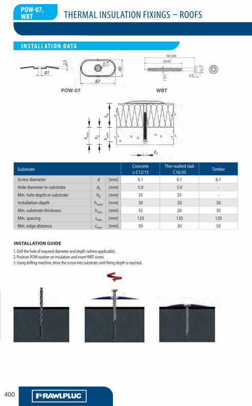
SubstrateConcrete≥C12/15
Thin-walledslabC16/20
Timber
Screwdiameter d [mm] 6.1 6.1 6.1
Holediameterinsubstrate d0 [mm] 5.0 5.0 -
Min.holedepthinsubstrate h0 [mm] 35 25 -
Installationdepth hnom [mm] 30 20 30
Min.substratethickness hmin [mm] 35 20 30
Min.spacing smin [mm] 120 120 120
Min.edgedistance cmin [mm] 30 30 50
1.Drilltheholeofrequireddiameteranddepth(whereapplicable).2.PositionPOWwasheroninsulationandinsertWBTscrew.3.Usingdrillingmachine,drivethescrewintosubstrateuntilfixingdepthisreached.
POW-07,WBT
LA CHEVILLENYLON MULTIFONCTIONS
I N S TA L L AT I O N DATA
d0
h min
h 0
h nom
t fix
THERMAL INSULATION FIXINGS – ROOFS
LA CHEVILLENYLON MULTIFONCTIONS
401
G
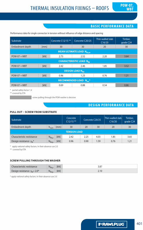
*partialsafetyfactor1.4**coveredbyETA
screwpullingthroughthePOWwasherisdecisive
Substrate ConcreteC12/15** ConcreteC20/25Thin-walledslab
C16/20Timber,
gradeC24
Embedmentdepth [mm] 30 30 20 30
MEAN ULTIMATE LOAD NRu,m
POW-07+WBT [kN] 2.73 2.52 2.20 3.64
CHARACTERISTIC LOAD NRk
POW-07+WBT [kN] 2.42 2.46 1.85 3.52
DESIGN LOAD NRd
POW-07+WBT [kN] 0.96 1.23 0.76 1.21
RECOMMENDED LOAD Nrec*
POW-07+WBT [kN] 0.69 0.88 0.54 0.86
Characteristicrestistance NRk,p [kN] 3.87
DesignresistanceγM=2.0* NRd,p [kN] 2.10
SCREW PULLING THROUGH THE WASHER
*applynationalsafetyfactors.Intheirabsenceuse2.0**coveredbyETA
SubstrateConcreteC12/15**
ConcreteC20/25Thin-walledslab
C16/20Timber,
gradeC24
Embedmentdepth hnom [mm] 30 20 30 20 30
TENSION LOAD
Characteristicrestistance NRk,p [kN] 2.42 2.25 4.03 1.85 3.65
DesignresistanceγM* NRd,p [kN] 0.96 0.90 1.59 0.76 1.21
*applynationalsafetyfactors.Intheirabsenceuse2.0
PULL OUT – SCREW FROM SUBSTRATE
LA CHEVILLENYLON MULTIFONCTIONS
B A S I C P E R F O R M A N C E DATA
LA CHEVILLENYLON MULTIFONCTIONS
D E S I G N P E R F O R M A N C E DATA
POW-07,WBT
Performancedataforsingleconnectorintensionwithoutinfluenceofedgedistanceandspacing
THERMAL INSULATION FIXINGS – ROOFS
LA CHEVILLENYLON MULTIFONCTIONS
AA402
G
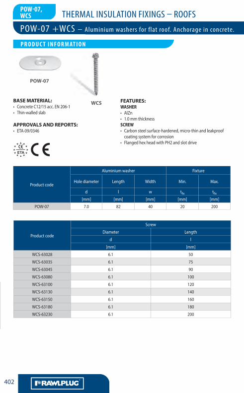
BASE MATERIAL:• ConcreteC12/15acc.EN206-1• Thin-walledslab
APPROVALS AND REPORTS:• ETA-09/0346
FEATURES:WASHER• AlZn• 1.0mmthicknessSCREW• Carbonsteelsurface-hardened,micro-thinandleakproofcoatingsystemforcorrosion
• FlangedhexheadwithPH2andslotdrive
POW-07
WCS
Productcode
Screw
Diameter Length
d l
[mm] [mm]
WCS-63028 6.1 50
WCS-63035 6.1 75
WCS-63045 6.1 90
WCS-63080 6.1 100
WCS-63100 6.1 120
WCS-63130 6.1 140
WCS-63150 6.1 160
WCS-63180 6.1 180
WCS-63230 6.1 200
Productcode
Aluminiumwasher Fixture
Holediameter Length Width Min. Max.
d l w tfix tfix[mm] [mm] [mm] [mm] [mm]
POW-07 7.0 82 40 20 200
POW-07,WCS
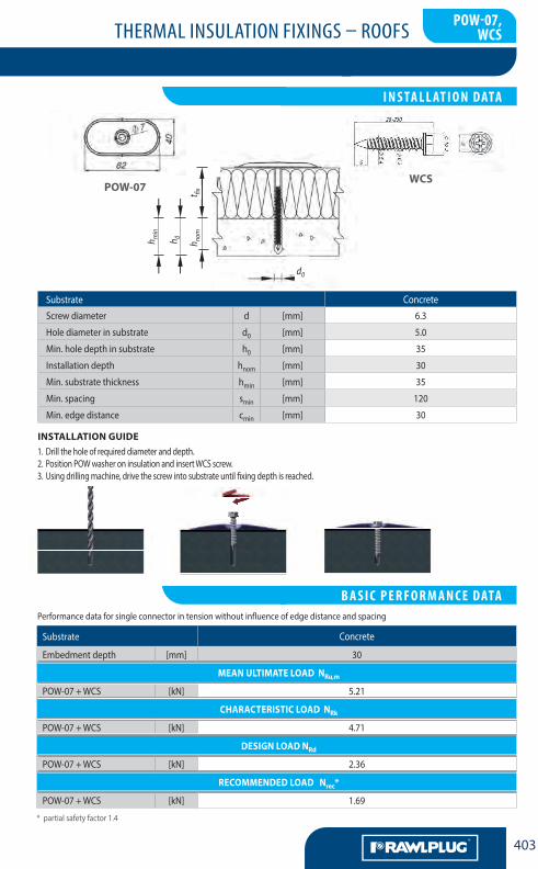
POW-07 +WCS – Aluminium washers for flat roof. Anchorage in concrete.
LA CHEVILLENYLON MULTIFONCTIONS
P R O D U C T I N F O R M AT I O N
THERMAL INSULATION FIXINGS – ROOFS
LA CHEVILLENYLON MULTIFONCTIONS
403
G
POW-07
1.Drilltheholeofrequireddiameteranddepth.2.PositionPOWwasheroninsulationandinsertWCSscrew.3.Usingdrillingmachine,drivethescrewintosubstrateuntilfixingdepthisreached.
INSTALLATION GUIDE
*partialsafetyfactor1.4
Substrate Concrete
Embedmentdepth [mm] 30
MEAN ULTIMATE LOAD NRu,m
POW-07+WCS [kN] 5.21
CHARACTERISTIC LOAD NRk
POW-07+WCS [kN] 4.71
DESIGN LOAD NRd
POW-07+WCS [kN] 2.36
RECOMMENDED LOAD Nrec*
POW-07+WCS [kN] 1.69
POW-07,WCS
LA CHEVILLENYLON MULTIFONCTIONS
B A S I C P E R F O R M A N C E DATA Performancedataforsingleconnectorintensionwithoutinfluenceofedgedistanceandspacing
LA CHEVILLENYLON MULTIFONCTIONS
I N S TA L L AT I O N DATA
Substrate ConcreteScrewdiameter d [mm] 6.3
Holediameterinsubstrate d0 [mm] 5.0
Min.holedepthinsubstrate h0 [mm] 35
Installationdepth hnom [mm] 30
Min.substratethickness hmin [mm] 35
Min.spacing smin [mm] 120
Min.edgedistance cmin [mm] 30
d0
h min
h 0
h nom
t fix
WCS
THERMAL INSULATION FIXINGS – ROOFS
LA CHEVILLENYLON MULTIFONCTIONS
AA404
G
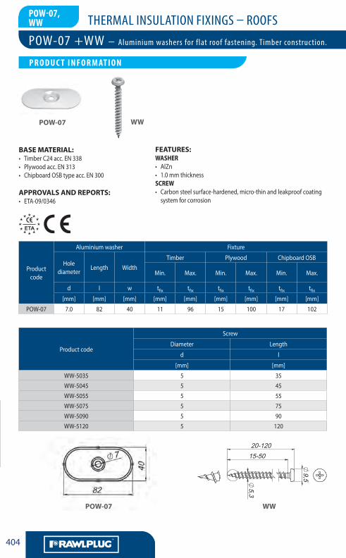
BASE MATERIAL:• TimberC24acc.EN338• Plywoodacc.EN313• ChipboardOSBtypeacc.EN300
APPROVALS AND REPORTS:• ETA-09/0346
Productcode
Aluminiumwasher Fixture
Holediameter
Length WidthTimber Plywood ChipboardOSB
Min. Max. Min. Max. Min. Max.
d l w tfix tfix tfix tfix tfix tfix[mm] [mm] [mm] [mm] [mm] [mm] [mm] [mm] [mm]
POW-07 7.0 82 40 11 96 15 100 17 102
POW-07 WW
FEATURES:WASHER• AlZn• 1.0mmthicknessSCREW• Carbonsteelsurface-hardened,micro-thinandleakproofcoatingsystemforcorrosion
Productcode
Screw
Diameter Length
d l
[mm] [mm]
WW-5035 5 35
WW-5045 5 45
WW-5055 5 55
WW-5075 5 75
WW-5090 5 90
WW-5120 5 120
POW-07 WW
POW-07,WW
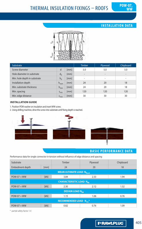
POW-07 +WW – Aluminium washers for flat roof fastening. Timber construction.
LA CHEVILLENYLON MULTIFONCTIONS
P R O D U C T I N F O R M AT I O N
THERMAL INSULATION FIXINGS – ROOFS
LA CHEVILLENYLON MULTIFONCTIONS
405
G
1.PositionPOWwasheroninsulationandinsertWWscrew.2.Usingdrillingmachine,drivethescrewintosubstrateuntilfixingdepthisreached.
INSTALLATION GUIDE
*partialsafetyfactor1.4
Substrate Timber Plywood Chipboard
Embedmentdepth [mm] 24 20 18
MEAN ULTIMATE LOAD NRu,m
POW-07+WW [kN] 3.84 2.33 1.94
CHARACTERISTIC LOAD NRk
POW-07+WW [kN] 2.30 2.12 1.52
DESIGN LOAD NRd
POW-07+WW [kN] 1.15 1.06 0.76
RECOMMENDED LOAD Nrec*
POW-07+WW [kN] 0.82 0.76 1.09
POW-07,WW
LA CHEVILLENYLON MULTIFONCTIONS
I N S TA L L AT I O N DATA
LA CHEVILLENYLON MULTIFONCTIONS
B A S I C P E R F O R M A N C E DATA
Substrate Timber Plywood Chipboard
Screwdiameter d [mm] 5.0 5.0 5.0
Holediameterinsubstrate d0 [mm] - - -
Min.holedepthinsubstrate h0 [mm] - - -
Installationdepth hnom [mm] 24 20 18
Min.substratethickness hmin [mm] 24 20 18
Min.spacing smin [mm] 120 120 120
Min.edgedistance cmin [mm] 30 30 30
Performancedataforsingleconnectorintensionwithoutinfluenceofedgedistanceandspacing
h nom
t fix
THERMAL INSULATION FIXINGS – ROOFS
LA CHEVILLENYLON MULTIFONCTIONS
AA406
G
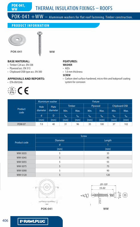
BASE MATERIAL:• TimberC24acc.EN338• Plywoodacc.EN313• ChipboardOSBtypeacc.EN300
APPROVALS AND REPORTS:• ETA-09/0346
Productcode
Aluminiumwasher Fixture
Holediameter
Platediameter
Timber Plywood ChipboardOSB
Min. Max. Min. Max. Min. Max.
d D tfix tfix tfix tfix tfix tfix[mm] [mm] [mm] [mm] [mm] [mm] [mm] [mm]
POW-07 7.0 40 31 96 35 100 37 102
POK-041
POK-041
WW
WW
FEATURES:WASHER• AlZn• 1.0mmthicknessSCREW• Carbonsteelsurface-hardened,micro-thinandleakproofcoatingsystemforcorrosion
Productcode
Screw
Diameter Length
d l
[mm] [mm]
WW-5035 5 35
WW-5045 5 45
WW-5055 5 55
WW-5075 5 75
WW-5090 5 90
WW-5120 5 120
POk-041,WW
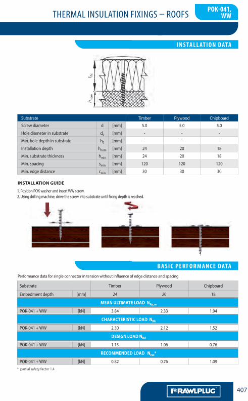
POK-041 +WW – Aluminium washers for flat roof fastening. Timber construction.
LA CHEVILLENYLON MULTIFONCTIONS
P R O D U C T I N F O R M AT I O N
THERMAL INSULATION FIXINGS – ROOFS
LA CHEVILLENYLON MULTIFONCTIONS
407
G
1.PositionPOKwasherandinsertWWscrew.2.Usingdrillingmachine,drivethescrewintosubstrateuntilfixingdepthisreached.
INSTALLATION GUIDE
*partialsafetyfactor1.4
Substrate Timber Plywood Chipboard
Embedmentdepth [mm] 24 20 18
MEAN ULTIMATE LOAD NRu,m
POK-041+WW [kN] 3.84 2.33 1.94
CHARACTERISTIC LOAD NRk
POK-041+WW [kN] 2.30 2.12 1.52
DESIGN LOAD NRd
POK-041+WW [kN] 1.15 1.06 0.76
RECOMMENDED LOAD Nrec*
POK-041+WW [kN] 0.82 0.76 1.09
Substrate Timber Plywood Chipboard
Screwdiameter d [mm] 5.0 5.0 5.0
Holediameterinsubstrate d0 [mm] - - -
Min.holedepthinsubstrate h0 [mm] - - -
Installationdepth hnom [mm] 24 20 18
Min.substratethickness hmin [mm] 24 20 18
Min.spacing smin [mm] 120 120 120
Min.edgedistance cmin [mm] 30 30 30
POk-041,WW
LA CHEVILLENYLON MULTIFONCTIONS
I N S TA L L AT I O N DATA
LA CHEVILLENYLON MULTIFONCTIONS
B A S I C P E R F O R M A N C E DATA Performancedataforsingleconnectorintensionwithoutinfluenceofedgedistanceandspacing
h nom
t fix
THERMAL INSULATION FIXINGS – ROOFS
LA CHEVILLENYLON MULTIFONCTIONS
AA408
G
NOTES


![Roofs - rules of using thermal insulation on rafter and ... projektavimo katalogas [en].pdf · 2 Roofs - rules of using thermal insulation on rafter and flat reinforced-concrete roofs.](https://static.fdocuments.in/doc/165x107/5c778e6309d3f2a94e8bf33b/roofs-rules-of-using-thermal-insulation-on-rafter-and-projektavimo-katalogas.jpg)