
Technical Guidelines for Machinery and Equipment...EN 1037:2008 Safety of machinery – Prevention...
90
voestalpine Tubulars GmbH & Co KG Technical Guidelines for Machinery and Equipment Page 1 of 90 Technical Guidelines for Machinery and Equipment Version January 23, 2018 Applicability: These guidelines for machinery and equipment are an integral part of agreements when purchasing machinery and equipment. If the CO deems that deviations from these specifications are necessary or appropriate, then these are to be agreed separately in writing with the CP. Abbreviations: CP = Contracting Party CO = Contractor
Transcript of Technical Guidelines for Machinery and Equipment...EN 1037:2008 Safety of machinery – Prevention...

voestalpine Tubulars GmbH & Co KG
Technical Guidelines for Machinery and Equipment
Page 1 of 90
Technical Guidelines for Machinery
and Equipment
Version January 23, 2018
Applicability:
These guidelines for machinery and equipment are an integral part of agreements when purchasing
machinery and equipment.
If the CO deems that deviations from these specifications are necessary or appropriate, then these
are to be agreed separately in writing with the CP.
Abbreviations:
CP = Contracting Party
CO = Contractor

voestalpine Tubulars GmbH & Co KG
Technical Guidelines for Machinery and Equipment
Page 2 of 90
Change Index
Date of Change Chapter
14.01.2015 3.1, 3.3, 3.4.1, 3.4.2, 3.6.2, 3.6.3, 3.6.4, 3.6.5, 3.7.1, 3.7.2, 3.7.3, 3.7.4, 3.7.5,
3.8.1, 4.2.8, 5.7, 7
24.04.2015 1.3, 5.3.4, 5.5, 5.7
30.04.2015 1.3
01.12.2015 2.5, 3.1, 3.6.2, 3.6.3, 3.6.4, 3.6.6, 3.7.4, 3.7.6, 3.8, 3.9.2
23.01.2018
1.3, 1.4, 1.5, 1.6, 1.7, 2.2, 2.5, 2.6, 3.6.1, 3.6.2, 3.6.3, 3.6.4, 3.6.6, 3.6.7, 3.7.4,
3.7.6, 3.8, 3.9.3, 4.1.1, 4.1.2, 4.2.2, 4.2.3, 4.2.4, 4.2.5, 4.2.6, 4.2.7, 4.2.8, 4.2.9,
4.2.10, 4.2.11, 4.3.8, 4.4.1, 4.4.2, 4.5.1, 4.5.6, 5.3.1, 5.5.4, 5.8, 5.9, 5.10, 6, 7.1,
7.2, 7.3, 7.4, 8.2, 8.3.1, 8.3.3, 8.3.3.1-8, 8.4, 8.4.1-8, 8.5, 8.6, 8.7, 9

voestalpine Tubulars GmbH & Co KG
Technical Guidelines for Machinery and Equipment
Page 3 of 90
Table of Contents
1 General information ...................................................................................................................................... 7
1.1 Rules of engineering .................................................................................................................................. 7
1.2 Spare parts stock ........................................................................................................................................ 7
1.3 General conditions ..................................................................................................................................... 7
1.4 Applicable standards and regulations ................................................................................................. 8
1.5 CE-marking for concatenated machinery or equipment .............................................................. 10
1.6 Subcontractor adherence to guidelines ............................................................................................ 10
1.7 Additional conditions .............................................................................................................................. 10
2 Tasks .............................................................................................................................................................. 10
2.1 Duty to obtain information .................................................................................................................... 10
2.2 Risk assessment ......................................................................................................................................... 10
2.3 Functional test ........................................................................................................................................... 11
2.4 Training ....................................................................................................................................................... 11
2.5 Technical documentation ...................................................................................................................... 11 2.5.1 General .......................................................................................................................................................... 11 2.5.2 Documentation of electrical equipment ........................................................................................... 13
2.6 Additional documentation documents for instrumentation and control of Furnaces........... 14
3 Mechanical specifications ......................................................................................................................... 15
3.1 General ....................................................................................................................................................... 15
3.2 Screws .......................................................................................................................................................... 15
3.3 Drives ........................................................................................................................................................... 15
3.4 Lubrication ................................................................................................................................................. 16 3.4.1 Oil and grease filling, Oil sight glass ................................................................................................... 16 3.4.2 Lubrication lines ......................................................................................................................................... 16 3.4.3 Manufacturers of small and medium-sized systems ..................................................................... 16
3.5 List of mechanics manufacturers ......................................................................................................... 16
3.6 Hydraulics .................................................................................................................................................. 17 3.6.1 General .......................................................................................................................................................... 17 3.6.2 Hydraulic pipes/tubes ............................................................................................................................. 17 3.6.3 Hydraulic tank, Oil level indicator ....................................................................................................... 17 3.6.4 Hydraulic accumulator ............................................................................................................................ 17 3.6.5 Inscription ..................................................................................................................................................... 18 3.6.6 List of hydraulics manufacturers .......................................................................................................... 18 3.6.7 Measurements ............................................................................................................................................ 19
3.7 Pneumatics................................................................................................................................................. 19 3.7.1 Air oiling ........................................................................................................................................................ 19 3.7.2 System separation ..................................................................................................................................... 19 3.7.3 Valves ............................................................................................................................................................ 19 3.7.4 Pipes and hose connection .................................................................................................................... 20 3.7.5 Inscription ..................................................................................................................................................... 20 3.7.6 List of pneumatics manufacturers ....................................................................................................... 20

voestalpine Tubulars GmbH & Co KG
Technical Guidelines for Machinery and Equipment
Page 4 of 90
3.8 Pipelines ...................................................................................................................................................... 21
3.9 Operating data......................................................................................................................................... 21 3.9.1 Compressed air .......................................................................................................................................... 21 3.9.2 Central hydraulics WT1, WT2, SRA ....................................................................................................... 22 3.9.3 Water ............................................................................................................................................................. 22
4 Electrical specifications.............................................................................................................................. 23
4.1 Installation of switch cabinets ............................................................................................................... 23 4.1.1 General .......................................................................................................................................................... 23 4.1.2 Identification system ................................................................................................................................ 23 4.1.3 Location of parts ....................................................................................................................................... 24 4.1.4 Location of terminal strips/cable fittings .......................................................................................... 24 4.1.5 Free space .................................................................................................................................................... 24 4.1.6 Switch cabinet climate control .............................................................................................................. 24 4.1.7 Protection class .......................................................................................................................................... 25 4.1.8 Service socket and switch gear cabinet lighting ............................................................................ 25
4.2 Installation guidelines ............................................................................................................................. 25 4.2.1 Cables and conductors ........................................................................................................................... 25 4.2.2 Standard cables ......................................................................................................................................... 26 4.2.3 Special cables ............................................................................................................................................. 26 4.2.4 Movable cable routing ............................................................................................................................ 26 4.2.5 Terminal strips ............................................................................................................................................. 27 4.2.6 Connection of sensors .............................................................................................................................. 27 4.2.7 Identifying parts and cables .................................................................................................................. 27 4.2.8 Switching devices ....................................................................................................................................... 27 4.2.9 Electrical drives and associated equipment .................................................................................... 27 4.2.10 Signalling devices ...................................................................................................................................... 27 4.2.11 Conductor colors ....................................................................................................................................... 28
4.3 Electrical supply, protective measures ............................................................................................... 28 4.3.1 Main voltage ............................................................................................................................................... 28 4.3.2 Protective measures ................................................................................................................................. 28 4.3.3 Control circuits ............................................................................................................................................ 29 4.3.4 Power supplies and control transformers .......................................................................................... 29 4.3.5 Potential equalization .............................................................................................................................. 29 4.3.6 Protecting transformers from overloading ....................................................................................... 29 4.3.7 Switching inductive loads ....................................................................................................................... 30 4.3.8 EMC-conform installation ....................................................................................................................... 30 4.3.9 Operation and protection of induction motors .............................................................................. 31
4.4 Control equipment, operator interface .............................................................................................. 31 4.4.1 EMERGENCY STOP device ...................................................................................................................... 31 4.4.2 Operating modes ...................................................................................................................................... 31 4.4.3 Faults and alarms ...................................................................................................................................... 32
4.5 Programmable control systems ............................................................................................................ 32 4.5.1 Selection and setup .................................................................................................................................. 32 4.5.2 Installation ................................................................................................................................................... 33 4.5.3 Interfaces ...................................................................................................................................................... 33 4.5.4 Decentralization ........................................................................................................................................ 33 4.5.5 ASI bus ........................................................................................................................................................... 33 4.5.6 Programming languages ........................................................................................................................ 33 4.5.7 Program structure...................................................................................................................................... 33 4.5.8 Simatic S7 protection levels ................................................................................................................... 34 4.5.9 Safety controllers ....................................................................................................................................... 34

voestalpine Tubulars GmbH & Co KG
Technical Guidelines for Machinery and Equipment
Page 5 of 90
4.6 CNC systems and industrial computers .............................................................................................. 34
5 Specifications for instrumentation and control of Furnaces ............................................................... 35
5.1 Accessibility ................................................................................................................................................ 35
5.2 S7/Software ............................................................................................................................................... 35 5.2.1 Structure........................................................................................................................................................ 35 5.2.2 General Information ................................................................................................................................. 36
5.3 Pipes............................................................................................................................................................. 36 5.3.1 Impulse pipes .............................................................................................................................................. 36 5.3.2 Grounding and paintwork ...................................................................................................................... 37 5.3.3 Pipes for Ignition Burner .......................................................................................................................... 37
5.4 UV-Sensor and Ignition burner ............................................................................................................. 37
5.5 Measurements .......................................................................................................................................... 37 5.5.1 Quantity Measurements ......................................................................................................................... 37 5.5.2 Oxygen Measurements ........................................................................................................................... 37 5.5.3 Exhaust Measurements ........................................................................................................................... 37 5.5.4 Pyrometer Measurements ...................................................................................................................... 38
5.6 Switch cabinets ......................................................................................................................................... 38
5.7 Limit values ................................................................................................................................................ 38
5.8 Thermocouples ......................................................................................................................................... 38
5.9 Cooling of electrical components ........................................................................................................ 39
5.10 Water cooling on industrial furnaces .................................................................................................. 39
6 Industrial Computers .................................................................................................................................. 39
7 APPENDIX A: Electrical parts (approved list) and documentation specifications ........................... 40
7.1 Electrical parts .......................................................................................................................................... 41
7.2 Selection list of the Phoenix modules .................................................................................................. 44
7.3 TIA approved list ....................................................................................................................................... 45
7.4 Documentation requirements ............................................................................................................... 49
8 APPENDIX B: voestalpine Tubulars S7 software specifications .......................................................... 51
8.1 Liability disclaimer .................................................................................................................................... 51
8.2 Hardware configuration / device view ............................................................................................... 51
8.3 Structuring .................................................................................................................................................. 52 8.3.1 Programming languages and standard software ......................................................................... 52 8.3.2 Program structure...................................................................................................................................... 52 8.3.3 Folder structure .......................................................................................................................................... 53
8.4 PLC variables ............................................................................................................................................. 57 8.4.1 Input / output variables .......................................................................................................................... 58 8.4.2 FU input / output variables / other fieldbus devices .................................................................... 59 8.4.3 Flag assignment: general ....................................................................................................................... 60 8.4.4 Flag assignment: operating mode ...................................................................................................... 61 8.4.5 Flag assignment: drive ............................................................................................................................. 61 8.4.6 Bypass Flag .................................................................................................................................................. 62 8.4.7 “Don’t know yet” ........................................................................................................................................ 62 8.4.8 Parameters ................................................................................................................................................... 62
8.5 Structure of functions .............................................................................................................................. 63

voestalpine Tubulars GmbH & Co KG
Technical Guidelines for Machinery and Equipment
Page 6 of 90
8.5.1 Safety program .......................................................................................................................................... 63 8.5.2 General .......................................................................................................................................................... 66 8.5.3 Equipment areas ........................................................................................................................................ 69 8.5.4 Messages ...................................................................................................................................................... 72
8.6 PLC data types .......................................................................................................................................... 73 8.6.1 Safety data type: Not_Halt ................................................................................................................... 73 8.6.2 Safety data type: Schutztuer_ohne_Anford_entr ......................................................................... 74 8.6.3 Safety data type: Schutztuer_mit_Anford_entr ............................................................................. 74 8.6.4 Safety data type: Lichtgitter .................................................................................................................. 74 8.6.5 Safety data type: F_Signal_Allgemein ............................................................................................... 74 8.6.6 Safety data type: Sicherheitskreis_ohne_RUECKF ........................................................................ 74 8.6.7 Safety data type: Sicherheitskreis_mit_RUECKF ............................................................................ 74 8.6.8 Drive ............................................................................................................................................................... 75 8.6.9 Analogwerte_Typ ...................................................................................................................................... 76 8.6.10 Rampenbildner_Typ ................................................................................................................................. 76 8.6.11 Regler_Typ ................................................................................................................................................... 77 8.6.12 Betriebsstundenzaehler_Typ ................................................................................................................. 78 8.6.13 Mittelwert_Typ ............................................................................................................................................ 78 8.6.14 RACK_FLT_Typ ............................................................................................................................................ 78 8.6.15 Antrieb FU PPO4 (z.B. PDrive) ................................................................................................................ 78 8.6.16 Sinamics ........................................................................................................................................................ 79
8.7 Visualization .............................................................................................................................................. 86 8.7.1 Time synchronization ................................................................................................................................ 86 8.7.2 Operator logon .......................................................................................................................................... 86 8.7.3 Alarm messages ......................................................................................................................................... 86 8.7.4 Archiving ....................................................................................................................................................... 86 8.7.5 Display ........................................................................................................................................................... 87 8.7.6 Color regulations WinCC-OA ................................................................................................................. 89
9 APPENDIX C: VAT-Dokumentationsstruktur_Rev.0 .............................................................................. 90

voestalpine Tubulars GmbH & Co KG
Technical Guidelines for Machinery and Equipment
Page 7 of 90
1 General information
If it is not possible to adhere to these guidelines, then the voestalpine Tubulars project contact is to
be informed immediately. Modifications or additions must be approved in writing.
1.1 Rules of engineering
The supplier guarantees that the machinery and equipment that is to be offered or delivered meets
the specified and listed requirements for machinery and equipment and the features and properties
defined therein. Such machinery and equipment is to be implemented in accordance with the
generally acknowledged state of the art.
1.2 Spare parts stock
After the required number of drives, switching devices, hydraulic and pneumatic devices, etc. has
been defined, the contracting party is to be consulted so that we have the opportunity to adjust them
to our internal spare parts stock.
1.3 General conditions
All delivered machinery, machine parts, switch cabinets, and equipment must meet the guidelines,
standards, regulations and state of the art at the time they are introduced on the market.
It is especially important to adhere to the latest version of the following regulations:
» Applicable EU guidelines and those regulations that have been adopted into Austrian law,
especially:
» Machine Safety Regulation MSV2010
» Low Voltage Equipment Regulation in accordance with Low Voltage Directive 2014/35/EU
» Electromagnetic Compatibility Regulation (in accordance with EMC Directive 2004/108/EC)
» Harmonized European standards
» Recognized rules of engineering
» CE marking and any necessary declarations of conformity are to be applied
» Official requirements
» voestalpine Tubulars identification system (equipment abbreviations and location codes, will
be issued by the CP)
» Crane - Safety - Non-fixed load lifting attachments DIN EN 13 155

voestalpine Tubulars GmbH & Co KG
Technical Guidelines for Machinery and Equipment
Page 8 of 90
1.4 Applicable standards and regulations
PED 2014/68/EU
Pressure Equipment Directive
DGÜW-V Pressure Equipment Control Order
DIN 20066 Fluid technology – hose lines, dimensions, specifications
DIN 2403 Identification of pipelines according to the fluid conveyed
DIN 51524-3 Pressure fluids – Hydraulic oils – Part 3: HVLP hydraulic oils, Minimum
requirements
DIN 7991 Hexagon socket countersunk head cap screws (DIN EN ISO 10642)
DIN 912 Hexagon socket head cap screws (DIN EN ISO 4762)
DIN 916 Hexagon socket set screws with cup point (DIN EN ISO 4029)
DIN 931 Hexagon cap screws partially threaded
EN 1037:2008 Safety of machinery – Prevention of unexpected start-up
EN 1090 Execution of steel structures and aluminium structures
EN 12952, EN 12953 Water-tube boilers and auxiliary installations, Shell boilers
EN 13445 Unfired pressure vessels according to AD2000/HP0
EN 13480 Metallic industrial piping
EN 13675:2004+A1:2010 Safety of machinery – Safety requirements for tube forming and rolling
mills and their finishing line equipment
EN 50110 Operation of electrical installations
EN 60204-1 :2006 Safety of machinery – Electrical equipment of machines – Part 1:
General requirements
EN 61000-6-1 Electromagnetic compatibility (EMC) Generic standards – Immunity to
interference
EN 61000-6-2 Electromagnetic compatibility (EMC) Generic standards – Immunity to
interference for industrial environments
EN 61000-6-3 Electromagnetic compatibility (EMC) Generic standards – Emission
standard for residential, commercial and light-industrial environments
EN 61000-6-4 Electromagnetic compatibility (EMC) Generic standards – Immunity to
interference for industrial environments

voestalpine Tubulars GmbH & Co KG
Technical Guidelines for Machinery and Equipment
Page 9 of 90
EN 61439-1 :2013 Low-voltage switchgear and controlgear assemblies – Part 1: General
rules
EN 61439-2 :2011 Low-voltage switchgear and controlgear assemblies – Part 2: Power
switchgear and controlgear assemblies
EN 61496-1 :2013 Safety of machinery – Electro-sensitive protective equipment – Part 1:
General requirements and tests
EN 61784 Industrial communication networks - Profiles - Part 3-6: Functional safety
fieldbuses – Additional specifications for CPF 6 (IEC 61784-3-6: 2007)
EN 61800-3 Adjustable speed electrical power drive systems – EMC requirements
EN 61918 Industrial communication networks – Installation of communication
networks in industrial premises
EN 746-1 and EN 746-
2
Industrial thermoprocessing equipment
EN IEC 62061 Safety of machinery – Functional safety of electrical, electronic and
programmable electronic control systems
EN ISO 12100:2010 Safety of machinery – General principles for design – Risk assessment
and risk reduction
EN ISO 13849-1:2008 Safety of machinery – Safety-related parts of control systems – Part 1:
General principles for design
EN ISO 13849-2:2012 Safety of machinery – Safety-related parts of control systems – Part 2:
Validation
EN ISO 13850 Safety of machinery – Emergency stop function – Principles for design
EN ISO 13855:2010 Safety of machinery – Positioning of safeguards with respect to the
approach speeds of parts of the human body
EN ISO 13857:2008 Safety of machinery – Safety distances to prevent hazard zones being
reached by upper and lower limbs
EN ISO 14119:2014 Interlocking devices associated with guards – Principles for design and
selection
EN ISO 14120 Safety of machinery – General requirements for the design and
construction of fixed and movable guards
ISO 1219-1 Fluid power systems and components – Graphical symbols and circuit
diagrams – Part 1: Graphical symbols for conventional use and data-
processing applications
ÖNORM EN 7010 Graphic symbols; Safety colours and safety signs
ÖVE/ÖNORM
E 8001-6-61
Erection of electrical installations with low voltages
Part 6-61: Verification – Initial verification
ÖVE/ÖNORM
E 8001-6-63
Erection of electrical installations with low voltages
Part 6-63: Verification – Certification and reporting

voestalpine Tubulars GmbH & Co KG
Technical Guidelines for Machinery and Equipment
Page 10 of 90
1.5 CE-marking for concatenated machinery or equipment
Machinery and equipment that is concatenated with other machinery and equipment also has to
have a CE marking or a declaration of conformity. If the safety of the entire installation is dependent
on the interfaces to other parts (e.g. locks, emergency stop circuits), all specifications must be given
to the purchaser and the supplier of the connected parts in order to ensure the conformity of the
entire machinery/equipment chain.
In the case of machine parts, all information necessary to perform any required conformity tests and
risk assessment (in accordance with the EU machinery guideline or machine safety regulations) must
be made available to the purchaser.
1.6 Subcontractor adherence to guidelines
The CO is fully responsible to the CP for adherence to these guidelines. If the CO uses third parties to
fulfil the contracted services, then the third parties must be included in the obligation to adhere to
these guidelines.
1.7 Additional conditions
If there is reason to believe that the CO did not fully or only partly adhere to the electrical guidelines,
then the CP reserves the right to have the machinery/equipment audited by an independent
organization (e.g. TÜV, etc.) to determine whether the electrical installation adheres to the guidelines.
If any deficiencies are found, then the cost of the external audit and the costs of fully remedying the
deficiencies shall be borne by the CO.
2 Tasks
2.1 Duty to obtain information
The electrical equipment used must take into account the operating environment, the climatic
conditions, and any special existing conditions. The CO is obliged to obtain information about these
conditions.
2.2 Risk assessment
The documentation of the risk assessment must be handed over to the contracting party’s Basic
Engineering. When placing the order, the CP wants to know which protection level is planned since
the operating modes also need to be defined at this point in time.
If access to the hazardous areas during operation is required, the protective devices and the signal
processing equipment must meet at least a performance level PL = d / category 3 (EN13675-A.2).

voestalpine Tubulars GmbH & Co KG
Technical Guidelines for Machinery and Equipment
Page 11 of 90
2.3 Functional test
Before it is put into operation, the equipment should undergo a functional test. All settings must be
equivalent to the operating state after the functional test is completed. The CP is to receive a written
test report.
In general, each CO is responsible for his scope of delivery. This also includes proper functioning
across interfaces (e.g. overall functional of locking must work).
2.4 Training
Appropriate training for planning, operating, and maintenance personnel is to be defined in due time
in consultation with the CP.
It is agreed that both the CO and the CP will name a contact who will be responsible for all training
and educational activities.
The CO is to train the Contracting Party’s employees such that they are theoretically and practically
capable of supervising, operating, and maintaining the delivered equipment. The training will not
only cover service and operating tasks during normal, problem-free operation. It will also include
activities related to start up, shut down, and what to do in the case of failures and problems.
The Contracting Party’s personnel will complete the necessary external and internal theoretical
training and when possible take the exams and take part in putting the equipment into operation.
The Contractor’s personnel will provide the necessary information and consulting services. If possible,
the practical training will take place during the installation and test operation under the supervision
of the Contractor’s experts.
The specific dates of the training activities will be jointly defined based on the availability and
working hours of the Contracting Party’s personnel.
2.5 Technical documentation
2.5.1 General
The technical documentation is an integral part of each piece of machinery/equipment. The
execution
and scope must meet the applicable European standards included all cross-references to IEC
publications as well as the scope of delivery at acceptance.
All documents must be created by the contractor in German.
The “preliminary documentation” must be delivered at least 2 weeks before commissioning 1 x on
disk (CD or DVD) and the e-plans 1 x on paper. The “as-built documentation” is part of the positive
acceptance and must be delivered 1 x on disk (CD or DVD) and 2 x on paper.
The disk documentation must correspond 1:1 to the paper documentation.
The documentation must be delivered in the form of the stipulated voestalpine Tubulars
documentation structure (Appendix C: VAT-Dokumentationsstruktur_Rev.0) including table of
contents. The file formats to be delivered can be found in the “VAT-Dokumentationsstruktur_Rev.0”
table.
The folder to be populated is available at http://www.voestalpine.com/tubulars/de/downloads/ .

voestalpine Tubulars GmbH & Co KG
Technical Guidelines for Machinery and Equipment
Page 12 of 90
All documents must be clearly named.
e.g.: Assembly and operating instructions for helical gearboxes and bevel helical gearboxes of the
X_20284535 series.
Only short names are permitted (e.g. 20284535) is not allowed!
The following contents are required in the documentation:
» Precise installation plans including all machine parts and modules
» Production drawings including all wear parts
» Hydraulic and pneumatic schematics in accordance with ISO 1219-1 and ISO 1219-2
» Lubrication plans with lubrication point position numbers and corresponding lubrication
instructions or lubrication chart!
» List of the delivered production drawings
» Parts list for all assemblies. The delivered drawings are to be marked with yellow in the parts
lists!
» For conversions of existing systems, the contractor’s existing parts lists must be updated by
the contracting party!
» Handbook and instruction manual
» Maintenance and repair instructions with the necessary engineering plans
» Data sheets of all purchased parts
» Spare parts lists for a three-shift operation, unless otherwise stipulated by the contracting
party.
» The following information is required:
o Position number
o Drawing number
o Material
o Installed quantity
o Recommended spare parts quantity
o Manufacturer
o Manufacturer type
o Item number
» When using explosive substances (gases, solvents, dust), any necessary information needed
to create an explosion protection document (in acc. with VEXAT) must be submitted to the
purchaser.
» In the case of machinery and equipment that is concatenated with other machinery and
equipment, all specifications for the connected parts must be given to the purchaser and
supplier in order to ensure conformity of the entire machinery/equipment chain (e.g.
information about locks, emergency stop circuits).
» In the case of machine parts, all information necessary to perform any required conformity
tests and risk assessment (in accordance with the EU machinery guideline or machine safety
regulations) must be made available to the purchaser.

voestalpine Tubulars GmbH & Co KG
Technical Guidelines for Machinery and Equipment
Page 13 of 90
2.5.2 Documentation of electrical equipment
2.5.2.1 Reports and documents
The following contents are required in the documentation:
For electrical installations:
» Initial verification report in accordance with ÖVE/ÖNORM E 8001-6-61 Erection of electrical
installations Section 6-61 – Verification – Initial verification
» Installation log book in accordance with ÖVE/ÖNORM E 8001-6-63 Erection of electrical
installations Part 6-63 – Verification – Certification and reporting
For machines:
» Start-up report; cold, warm, and function tests of the CO’s safety equipment
» Technical documentation, ÖVE EN 60204 test report and stop category in accordance with
» ÖVE EN 60204-1 Electrical equipment of machines
» Test report or design verification in accordance with ÖVE EN 60439 Low voltage switching
device combinations
» Risk assessment in accordance with EN 12100
» Indication of the performance level in accordance with EN 13849 or the SIL level in
» accordance with EN 62061 for safety shutdown of all Movements
» Assignment list of drives to control voltage switches, emergency stop buttons, and safety
door tumblers
» Power circuit diagrams are to be created in EPLAN P8 V2.6, saved as an archived project
(incl. symbols and parts management) on a CD-ROM and submitted with the above
documents
» All documentation is to be in electronic form on data storage devices and in PDF format
The structure of the documentation is shown in Appendix A by means of an example = 4MAA.
2.5.2.2 PLC software documentation
PLC programs are to be submitted to the CP on a CD-ROM. The list format is A4 portrait. The software
version must be the latest version available at acceptance. Changes made by the manufacturer after
acceptance are to be immediately updated on the data storage device and in the customer’s written
documentation.
Documentation of the control system must include the following list in the order presented here:
» List of blocks and objects
» Symbol table
» Listing of the source program in the original representation (KOP, FUP, AWL, S7-SLC)
» Listing of data blocks (commented)
» Cross-reference list of all operands
» Assignment list for inputs, outputs, flags

voestalpine Tubulars GmbH & Co KG
Technical Guidelines for Machinery and Equipment
Page 14 of 90
The data storage device must contain all original data and source code generated when developing
the program, compiled executable programs, and a dump of the Contractor’s latest valid version.
2.5.2.3 Documentation for CNC controllers and industrial computers
If not provided in the standard scope of delivery, the following information must be submitted for
CNC controllers:
» Operating instructions
» Programming instructions
» Description of interfaces
» Documentation of the PLC and NC programs
» Machine data, R parameter lists
» Ghost of the hard drive including relevant ghost versions as a data backup on DVD
CD-ROM is the approved data storage device. If available, technical manuals for the hardware and
operating systems of industrial computers are to be submitted as well as the licenses for installed
software, including all manuals and data storage devices.
2.5.2.4 Installed components and systems
If available, technical documentation and data sheets for electronic components and subsystems
that suffice for required maintenance and servicing are to be submitted. Purchased parts that do not
have service documents or for which service cannot be guaranteed cannot be used. A list of
manufacturers for OEM parts with information about national service locations must be contained in
the technical documentation.
2.6 Additional documentation documents for instrumentation and
control of Furnaces
» Flow schema
» Plan of measuring points
» 3D CAD drawings of the pipes
» Equipment list (including calculations)
» Burner documentation including pressure curves for combustion air and fuel gas

voestalpine Tubulars GmbH & Co KG
Technical Guidelines for Machinery and Equipment
Page 15 of 90
3 Mechanical specifications
3.1 General
All machine parts must be easy and safe to access for repair. Every piece of the equipment must
function properly and be made of the material best suited for the intended use. The materials must
be coordinated so that they function well together.
All equipment parts that need to be operated, regularly inspected or maintained must be safely
accessible using appropriate walkways or platforms.
Mounting aids for inaccessible assemblies have to be in scope of supply, ( special lifting device,
slings).
In order to keep the contracting party's storage costs low, components identical to the ones presently
used by the contracting party are to be used if possible. Function or technical progress should not be
restricted. For this reason, the contracting party must be informed about the planning progress at
regular intervals.
Contractor and contracting party must agree on the use of spare and wearing parts.
Hydraulic power units, control elements and valve stands (hydraulic / pneumatic), as well as
lubrication systems are to be installed outside of protective fences.
3.2 Screws
The following screws should preferably be used:
» Hexagon socket cap screws DIN 912
» Hexagon screws DIN 931
» Socket set screws DIN 916
» Countersunk head screws DIN 7991
3.3 Drives
If only one turning direction is allowed for drive shafts and spindles, then this must be indicated with a
conspicuous arrow.
Every gear box and gear motor has to have a nameplate on which you can read gear ratio, number
of revolution and serial number.

voestalpine Tubulars GmbH & Co KG
Technical Guidelines for Machinery and Equipment
Page 16 of 90
3.4 Lubrication
All lubrication points must be marked on the machinery and equipment as specified in the lubrication
and maintenance schedule.
If technically feasible, maintenance-free elements are to be used. Automatic central lubrication is to
be used where it makes sense or is expressly requested.
When connecting to an existing dual-line central lubrication system, ZV-B or ZV-C distributors from
Bijur Delimon are to be used.
Manual lubrication points are not permitted.
3.4.1 Oil and grease filling, Oil sight glass
Sight glasses of gear boxes, lubricant container and so on should be readable without entering the
safety area. The three levels for min, max and operating condition must be easy to read.
The filling and refilling should be possible without technical aids (ladder) and from outside the safety
area.
3.4.2 Lubrication lines
The guidelines for lubrication lines refer to the guidelines for hydraulic lines. (3.6.2)
The connection for lubricating lines can be made using a cutting ring connection.
3.4.3 Manufacturers of small and medium-sized systems
Material Supplier
Progressive distributors Bijur Delimon, BekaLube
Single line distributors Bijur Delimon, BekaLube
3.5 List of mechanics manufacturers
Material Supplier
Rolling bearings SKF, INA, FAG, NSK, TIMKEN
Cardan shafts Voith, Elbe, GWB
Gear couplings Malmedie, Flender
Elastic couplings KTR, Stromag, Rexnord, Flender
Gear motors Bauer, SEW Eurodrive, NORD
Pumps for industrial water EGGER, KSB, Xylem
Cooling tower COFELY Kältetechnik

voestalpine Tubulars GmbH & Co KG
Technical Guidelines for Machinery and Equipment
Page 17 of 90
3.6 Hydraulics
3.6.1 General
Hydraulic equipment is to be installed in accordance with the currently valid DIN standards. Only
original parts (e.g. valves, devices, etc.) that have not been changed whatsoever can be installed and
used. The connection to the central hydraulic system must be equipped with safety valves.
The equipment for the pressure generating system with redundant main pump unit, or the use of a
circulation system and filter system (e.g. with differential pressure monitoring) is requirement-specific
and is to be agreed upon with the contractor in the course of the project.
3.6.2 Hydraulic pipes/tubes
Installation and layout of hose lines must be performed according to DIN 20066.
The inside walls of pipes and tubes must be cleaned before final installation. Pipelines that end (P/T/L)
are to be closed with plugs.
If pipes have contact with water and scale they have to be made of stainless steel (1.4571, 1.4541).
Hoses which are exposed to radiant heat have to be delivered with protection coat. Hose dimensions
and fittings must be written down in the documentation.
The marking of pipes must be in accordance to DIN 2403.
In the case that rust-free metals are not used for pipelines, they must be painted thoroughly in the
colour of the hydraulic medium.
The pipe connections to the consumers are to be made with pipe threads according to ISO 228-1 or
with SAE flanges.
3.6.3 Hydraulic tank, Oil level indicator
In principle there is hydraulic oil in accordance to ISO VG 46, DIN 51524/Teil 2 to use.
If the tank has a capacity of 1000l or more the tank has to be equipped with to additional
connections (R 2”) and stopcock. (additional draining, filtering, emptying)
The three levels for min, max and operating condition must be easy to read. Also there has to be a
marking for those three levels.
If no circulating system with flow heater is included, a tank heater is to be provided. For tank volumes
> 1000l, a water content warning must be installed. For the tank, a collection tray with half the tank
volume should be provided.
3.6.4 Hydraulic accumulator
The usage of hydraulic accumulators shall be in accordance to the pressure vessel regulation DGVO
and DGÜW-VO. All required documents and the proof for fatigue strength are to deliver. Only
storage reservoirs of test level 1 should be used. Bubble accumulators are preferred. The
accumulators have to be equipped with an automatic relief valve at the oil side.
The pressure vessel and the safety valve must be mounted so that the manufacturer's instructions can
be read without any aids. The storage capacity must be determined during the design process.

voestalpine Tubulars GmbH & Co KG
Technical Guidelines for Machinery and Equipment
Page 18 of 90
3.6.5 Inscription
The hydraulic unit is named with an inscription plate which contains the name of the machine, plant
etc. and the drawing number of the hydraulic plan.
The plate is mounted at the associated valve stand or table. Function labels and type plates may not
be painted over.
All hydraulic components are lettered, as shown in the table below, on not removable plates in
accordance to the hydraulic plan.
Component Description
electrically operated valve function, direction, position number and electrical
labelling
pressure switch position number, pressure and electrical labelling
filter position number, manufacturer product name
hydraulic cylinders serial number
hydraulic accumulator manufacturer, year of manufacture, gas
pressure, volume
other components position number
All symbols are to be executed according to ISO 1219-1.
3.6.6 List of hydraulics manufacturers
Material Description Supplier
Hydraulic components and
accessories
Hydraulic cylinders
Series CDH1 or CDH2,
Seal version: M = standard
sealsystem
Bosch Rexroth
Float switch Type ABZMS-41, level and
temperature measurement (RTA) Bosch Rexroth
Valves
Switch valves with manual override
Proportional valves: Manual
overrides must be defined together
with the contracting party
Bosch Rexroth
Hydraulic fittings
DIN fittings, 24° sealing cone cutting
ring threaded connections are not
permitted
Ermeto, Walform
Hydraulic flanges for pressure lines SAE flange, AVIT square flanges GS-Hydro
Hydraulic flanges for tank lines DIN 2633 (low pressure flange PN 16)
Manometer With glycerine filling
Hydraulic cooling With plate heat exchanger To be defined with
the contractor
Hose lines 24° sealing cone connection for DIN
fittings

voestalpine Tubulars GmbH & Co KG
Technical Guidelines for Machinery and Equipment
Page 19 of 90
3.6.7 Measurements
Pressure transmitters with digital display to monitor the pressure generating system must be provided.
Minimess connections (G ¼") are to be applied as follows:
» Before each pressure control valve
» After each pressure reduction valve
» In the P, T, A, B lines
» Parallel to each pressure transducer and pressure switch
All values measured on the system must be wired into an intermediate terminal box. The
measurement of the values is to be coordinated with the contracting party.
The use of a particle counter with remote monitoring of oil quality in systems with proportional valves
must be defined separately with the contracting party.
3.7 Pneumatics
3.7.1 Air oiling
In case of pneumatic operated device is an air oiling possible. Preferred are pneumatic maintenance
units including filter, regulator and oiler with automatic condensate outlet.
The sealing elements of the components must be equipped with the appropriate material.
3.7.2 System separation
Every assembly that has its own decentralized controller can be separated from the system manually
and has to be depressurized by an electrically operated valve. (monitoring with pressure switch)
A sharp and sudden increase of the pressure must be prevented.
Ensure that all connections and adjustment screws are accessible.
3.7.3 Valves
Valves which are electro pneumatically actuated or pneumatically actuated have to have a
manually emergency function. Valve voltage 24V DC.
All Valves should be mounted in a cabinet with a view window.

voestalpine Tubulars GmbH & Co KG
Technical Guidelines for Machinery and Equipment
Page 20 of 90
3.7.4 Pipes and hose connection
If they are in contact with water and scale they have to be made of stainless steel. (1.4571, 1.4541)
For connections in dry area are polyamide pipes with plug-connection are possible.
The marking of pipes must be in accordance to DIN 2403.
In the case that rust-free metals are not used for pipelines, they must be painted thoroughly in the
colour of the hydraulic medium.
3.7.5 Inscription
The labelling is carried out as in the hydraulics (see 3.6.5).
3.7.6 List of pneumatics manufacturers
Material Description Supplier
Pneumatic components and
accessories
Pneumatic valves ISO sizes 1 to 4
(base mounting valves)
Festo, Norgren,
Aventics, Stasto
Pneumatic cylinders
ISO cylinder
Line connection
Pipe thread ISO 228-1
Festo, Norgren,
Aventics, Stasto
Pneumatic fittings DIN fittings 24° sealing cone
or push-in fittings

voestalpine Tubulars GmbH & Co KG
Technical Guidelines for Machinery and Equipment
Page 21 of 90
3.8 Pipelines
The pipelines are to be designed according to “voestalpine execution standards for pipe classes”.
These are available for download at http://www.voestalpine.com/tubulars/de/downloads/ .
An overview of the valid pipe classes is shown below.
max. Druck min. Temp. zul. Druck max. Temp. Druck Temp.
abgegeben am [bar] [°C] [bar] [°C] [bar] [°C]
1 EN-E10P abgegeben 23.10.2017 Heizkreisläufe ND 7,2 -10 6 90 6 90
2 EN-D16HG abgegeben 23.10.2017 Schmieröl Vorlauf 14 -20 10 100 10 70
3 EN-E16P abgegeben 23.10.2017Abwärme DF, Dampfkondensat nach
Kondensomat, Kühlwasser (geschlossener
Kreislauf)
16 -10 13 180 14,3 140
4 EN-E25PD abgegeben 23.10.2017Sattdampf nach Speicher, Prozeßdampf 12barü,
Dampfkondensat PD, Dampfkondensat SD25 -10 16 300 16 300
5 EN-E40P abgegeben 23.10.2017 Kesselspeisewasser 35 -10 30 150 30 150
6 EN-F100PK abgegeben 23.10.2017 Sattdampf vor Speicher, Dampfkondensat SD HD 95 -10 60 300 60 300
7 EN-F160PK abgegeben 23.10.2017 Dual Fuel 125 -10 116 150 116 150
8 EN-E16FH abgegeben 23.10.2017 Erdgas Werksnetz, Erdgas Betrieb Halle 10 -10 9,5 50 9,5 50
9 EN-E25NH abgegeben 23.10.2017 Stickstoff, Argon 25 -20 20 50 25 20
10 EN-E40NH abgegeben 23.10.2017Stickstoff 25bar GAN(rein), Stickstoff 14bar CGAN,
Argon25 -20 25 50 25 50
11 EN-R16AM abgegeben 23.10.2017 Ammoniakwasser 16 -10 9 25 9 25
12 EN-G100PK abgegeben 23.10.2017 Mitteldruckdampf, Dampfkondensat MD 100 -10 62 500 62 500
13 EN-R10CH abgegeben 23.10.2017Brunnenwasser, Trinkwasser,
Kreislaufkühlwasser10 -10 9 90 10 20
14 EN-R16DE abgegeben 23.10.2017 Deionat 16 -10 15 70 15 70
15 EN-R25CH abgegeben 23.10.2017 VE-Wasser 25 -10 21 100 25 20
16 EN-R40XT abgegeben 23.10.2017 Sauerstoff 25bar GOX 25 -10 20 100 25 40
17 EN-R16HG abgegeben 23.10.2017 Druckluft 6bar, Instrumentenluft 6bar 11 -10 9,5 100 10 50
18 EN-R16HV abgegeben 23.10.2017 Schmieröl Rücklauf 11 -10 10 100 10 70
19 EN-F040PK abgegeben 23.10.2017 DF-Kesselspeisewasser, DF-Dampf 40 -10 21 450 21 450
20 EN-E25FW abgegeben 23.10.2017 Fernwärme, Abwärme HBO 25 -10 20 140 20 140
21 EN-E040PK abgegeben 23.10.2017 DF-Kesselspeisewasser 40 -10 35 180 35 180
22 EN-E100PK abgegeben 23.10.2017 SD-Dampf, SD-Kondensat 100 -10 85 150 85 150
23 EN-E160PK abgegeben 23.10.2017 Kesselspeisewasser 130 -10 116 150 116 150
24 EN-D10JC-10bar abgegeben 23.10.2017 Kühlwasser, Nutzwasser, Reinwasser, Abwasser 10 -10 10 20 10 20
26 EN-R250PY abgegeben 23.10.2017 Hydrauliköl mineralisch 250 -10 250 80
27 EN-R3215PY abgegeben 23.10.2017 Hydrauliköl mineralisch 315 -10 315 80
(1) Einstufungen, Prüfungen, Anzugsmomente und Rohranbauteile, die in der Rohrklasse aufgelistet sind, beziehen sich auf Berechnungstemperatur
Berechnung (1)
lfd. Nummer Rohrklasse StatusDatum:
Medium
Gültigkeitsgrenzen der Rohrklasse
For requirements that deviate from the valid pipe classes, consult the contracting party.
The use of plastic pipes for service water distribution must be coordinated separately with the
contracting party.
3.9 Operating data
3.9.1 Compressed air
Site grid: p=6bar
Compressed air is technically dry with less content of oil and water.
Oilcontent: 0,1mg/m³
Dew point: +3°C
Particle size: 0,3µm

voestalpine Tubulars GmbH & Co KG
Technical Guidelines for Machinery and Equipment
Page 22 of 90
3.9.2 Central hydraulics WT1, WT2, SRA
The use of the central hydraulics is to be agreed with the contracting party.
Operating pressure: 120bar
Temperature: 40°C – 60°C
3.9.3 Water
Pressure Temperature Water hardness
Drinking water 3,5 bar 10°C 7,5°dH
Industrial water 5 bar 10°C 12°dH
Open circuit 4 bar 25°C 12°dH
Closed circuit 4 bar 21°C 12°dH
Chemical testing of groundwater containment probes from June 20, 2017
Groundwater BEFORE filling – results (depth 8.87 m)
Sample description: clear, colourless, odourless
Parameter Analysis method Unit Measure value Parameter value (Guide value)
#
Temperature DIN 38 404 - C 4 °C 10,4 (25)
pH value DIN 38 404 - C 5 -- 7,58 (6,5 - 9,5)
Electrical conductivity
conductivity
ÖNORM EN 27888 µS/cm 565 (2500)
Oxygen content DIN EN 25814 O2
mg/l
7,90 --
Oxygen saturation DIN EN 25814 % 75,7 --
Acid capacity up pH 4,3 DIN 38 409 - H 7 mmol/l 4,0 --
Carbonate hardness DIN 38 409 - H 7 °dH 11,2 --
Total hardness DIN 38 409 - H 6 °dH 11,4 --
Ammonium (NH4+) DIN 38 406 - E 5 mg/l 0,019 (0,5)
Nitrate (NO3) DIN 38 405 - D 9 mg/l 8,02 50
Nitrite (NO2) DIN EN 26777 mg/l <0,01 0,1
NO3 NO2 1
50 3
--
mg/l
0,16
≤ 1
Chloride (Cl) DIN 38 405 - D 1 mg/l 35,8 (200)
Sulfate (SO42-
) DIN 38 405 - D 5 mg/l 22,8 (250)
Iron (as Fe) analog DIN 38 406 –
E 28
mg/l 0,010 (0,2)
Manganese (as Mn) ÖNORM ISO 8288 mg/l 0,0010 (0,05)
TOC (as C) DIN EN 1484 mg/l <1,0 --
KW-index ÖNORM EN ISO
9377-2
mg/l <0,08 --
* On-site measurement, #parameter value (maximum permissible concentration) and standard values (indicator parameter)
acc. Appendix I to the drinking water ordinance, BGBl. II No. 304/2001 as amended.

voestalpine Tubulars GmbH & Co KG
Technical Guidelines for Machinery and Equipment
Page 23 of 90
4 Electrical specifications
4.1 Installation of switch cabinets
4.1.1 General
» Switch cabinets can only contain electrical parts, modules, or systems.
» The doors on the cabinets are not to be wider than 800 mm and are to be equipped with a
double-bit key lock. The depth of the cabinet is not to exceed 600 mm.
» The switch, control and distribution cabinets, including all installed components, must be easy
to access for maintenance and servicing.
» Control cabinets are to be used for command and signalling devices, text displays, and
control consoles. It is prohibited to use control cabinets as switch cabinets.
» Exceptions must be expressly agreed to by the CP. In cabinets that are 200 mm x 200 mm or
larger, terminal boxes and junction boxes with hinges must have a cover that opens 170
degrees.
» Wiring is to be done using plastic conduits on mounting plates.
» Devices in cabinets with hinged doors are to be connected using a protective tube or
multiconductor lines. If protective tubes are used, an extra spare wire is to be inserted for use
as a pulling wire.
» The wiring must adhere to the specified power circuit diagram.
» The wiring must be done with flexible conductors.
» Switching devices can have no more than two conductors per terminal point.
» A rotating field monitor as well as a combined surge arrester type 1/2 (DEHN TNS 255 FM)
with remote signalling contact must be installed on the machine feed switching cabinets.
4.1.2 Identification system
Voestalpine Tubulars has defined company-specific definitions for implementing the standard:
» Plant and function identification
» Location marking (control cabinets, operating console and terminal boxes, etc.)
» Terminal block labelling
» Cable labelling
» EPLAN resource and structure labelling specifications
These are described in Appendix A with an example = 4MAA and in the EPLAN sample project as well
as in the EPLAN base project.
The designation will be placed in a suitable location near the circuit symbol. It represents the
relationship between the part, the equipment, and the various circuit documents (circuit diagram,
parts list, electrical wiring diagrams, instructions). For easier servicing, the designations can be placed
completely or partially on or near the part.

voestalpine Tubulars GmbH & Co KG
Technical Guidelines for Machinery and Equipment
Page 24 of 90
4.1.3 Location of parts
Electrical parts that are not meant for panel mounting are not to be mounted on cabinet doors or
walls. They are only to be mounted on mounting plates and top hat rails designated for this purpose.
The parts should be arranged in clear, functional groups. Care must be taken to ensure adequate
space between the parts. The installed switching devices must be at least 0.2 m above the cabinet
floor. Devices that emit a lot of heat are to be mounted in the upper part of the cabinet.
4.1.4 Location of terminal strips/cable fittings
The spacing between the cable routing in the cabinet and the terminal strip above must be at least
150mm. A cable duct is to be installed below the terminal strip (see appendix).
The cables in the cabinet must be routed in accordance with the protection class of the cabinet and
must relieve tensile stress (C-rails). Any cable fittings must be plastic.
Each terminal strip can have no more than one conductor per terminal point. The use of loose
terminals is not permitted. All connections must be clamped or plugged connections. With the
exception of data and measuring conductors, no solder connections are allowed.
Screw terminals on all devices are to be equipped with a thrust piece, clamping bracket or sleeve to
protect the conductor.
Interconnections between adjacent terminals must be carried out using jumper bars (no jumper wires).
Differing potentials and control signals are to be placed on separate terminal strips. At least 10%
free space is to be maintained between the terminal blocks. Cable trays are to be mounted on both
ends of the terminal strips. Enough space must be left between the cable trays to replace a defective
device or terminal.
4.1.5 Free space
In switch cabinets and control cabinets, at least 20% of the available mounting space must be
reserved as free space. This space is to be divided into areas for the later mounting of terminals,
switching devices, and components.
4.1.6 Switch cabinet climate control
The climatic conditions for all parts, modules, and systems contained in a switch cabinet must adhere
to the respective manufacturer specifications. Under no circumstances should the air temperature
exceed 40 °C. The determination of the required climate control system must be calculated based on
a dissipation power calculation that the CP can follow. The climate control system is to be controlled
and monitored using a thermostat and door switches. Defects and overtemperatures must be
signalled to prevent electronic systems from failing due to overtemperature.
In a worst case situation, the ambient temperature in halls can reach 40 °C. For switch cabinets in
which there is high power dissipation, suitable cooling measures must be taken to make sure the
above-mentioned maximum temperature is not exceeded. Switch cabinets in the field are to be
equipped with water/air heat exchangers.

voestalpine Tubulars GmbH & Co KG
Technical Guidelines for Machinery and Equipment
Page 25 of 90
4.1.7 Protection class
Cabinets that are to be installed in the vicinity of the equipment/machine must have at least
protection class IP54. Cable conduits, fans, and other openings subsequently added to the cabinet
must not degrade the protection class. In general, open switch cabinets with a wooden block to
prevent stumbling are to be installed in the switch rooms.
4.1.8 Service socket and switch gear cabinet lighting
Internal cabinet lighting is required for cabinets that are at least 1,500 mm high. A door switch is to
be used to turn off the lighting when the cabinet is closed. A 230 V 50 Hz socket is required for repair
and servicing. This socket must be fed from the main switch and be protected with an LS-FI 13A circuit
breaker.
4.2 Installation guidelines
4.2.1 Cables and conductors
Only flexible conductors (stranded wire) are to be used to install machinery and equipment. Outside
the cabinets, the conductors and cables are to be equipped with trailing, oil-proof and/or acid-proof
insulation, depending on the environment. The ambient temperatures are also to be taken into
account when selecting cables.
Cables and conductors outside the cabinets are to be routed in designated cable trays, protective
tubes or hoses, or metal cable ducts. Under no circumstances are cables to be routed to equipment
or machine parts just as they are, or with easily disconnected connections, or in plastic ducts.
Each part is to be connected to the cabinet, terminal box, or fieldbus distributor using a separate,
flexible cable. Conductors from stranded conductors must have end sleeves for screw connections.
Soldered connections are not allowed. Shielded, twisted pair conductors are to be used for data lines.
Only shielded conductors are to be used for motor lines to frequency-controlled drives or servo
drives. Suitable, highly flexible conductors are to be used for connections to frequently moved parts.
They are to be mounted such that the conductor is subject to as little bending or tensile stress as
possible, especially at the fixing points. The conductor loop must be large enough that the minimum
permissible bending radius is maintained when moved. Conductors that are frequently moved must
be installed such that they can be plugged in before and after they are moved. All connections for
electrical parts (e.g. initiators, valve coils) must be plugged connections. If this is not possible, the
connecting conductor must be routed to the distribution board or control cabinet using the shortest
possible cable.

voestalpine Tubulars GmbH & Co KG
Technical Guidelines for Machinery and Equipment
Page 26 of 90
4.2.2 Standard cables
Standard cables Designation
Control cable YSLY-JZ, YSLY-OZ
Shielded control cable YSLCY-JZ, YSLCY-OZ
Hydraulics and exterior control cables H07RN-F, H05RN-F
Oil-resistant cables H05VVS-F (NYSLYö), S90
Oil-resistant, shielded cables H05VVC4V5-K (NYSLYCYö), S90C
Cables for high ambient temperatures SiHF
Cables for high ambient temperatures. Shielded SiFCuSi
Drag chain cables S80
Shielded drag chain cable S80C
Reeling cables NSHTöu(K)-J
Power cables NYY-J 3x ....
Power cables for motors NYY-J 4x ....
Shielded power cables for motors (Siemens drives) 2YSLCYK-J 4x..., 2YSLCY-J 4x....
Power cables for mobile devices SLM
Shielded power cables for mobile devices SLCM
Compensation line NiCrNi
Simatic inputs / outputs installation cable without power JE-LiYCY nx2x0,5 Bd Si gr; n=2, 4, 8 ….
4.2.3 Special cables
Special cables Designation
Profinet cable CAT 7
Profibus cable 6FX1830-0EH10
Profibus cables for mobile devices 6FX1830-0FH10
Cable for weighing HBMKAB09/00/-2/2/2
Fibre optic cable
Network cable CAT7
4.2.4 Movable cable routing
Cables that are bundled or routed in energy chains and often moved must be equipped with plugs
before and after the interfaces to the movable section so that only the movable part of the cable has
to be replaced in the case of wear. Energy chains have to be open on one end to make it easier to
replace defective cables. Cables and conductors must be specified for routing in energy chains or
regular movement. A terminal box can be alternatively used.

voestalpine Tubulars GmbH & Co KG
Technical Guidelines for Machinery and Equipment
Page 27 of 90
4.2.5 Terminal strips
Terminal strips are to be divided according to main or auxiliary electrical circuits. Each energy cable
must have a zero and protective earth output. Terminals and terminal strips are to be permanently
and clearly marked in agreement with the power circuit diagram. The terminals are to be sequentially
numbered from left to right. Each conductor is to have a terminal point. It is prohibited to have two
conductors in a single terminal.
4.2.6 Connection of sensors
For inductive or optical proximity sensors, only M8 and M12 round plug connectors for straight or 90 °
4-pin sockets are allowed. If there is no function or voltage display on the sensor, or it is installed such
that the display cannot be seen, then the cable sockets should each have an LED to indicate the
function and voltage display.
4.2.7 Identifying parts and cables
All electrical parts must be designated in accordance with the power circuit diagram. In the case of
cables, the designation must be located in a very visible location using label holders on cable ties
and must be resistant to abrasion, UV, water, oil, and solvents.
Part designations are to be mounted on machinery using oil-proof screwed or riveted plates (type to
be defined in the order confirmation) and must conform to EN/IEC 61346. Switching device
designations must be in accordance with the circuit diagram and are to be mounted on both the
device and the mounting plate. Internal cabling must be labelled with conductor numbers in
accordance with the connecting terminal designation. PLC I/O cards must be labelled with the
absolute address of the respective part designation.
4.2.8 Switching devices
Only approved standard electronics products listed in the voestalpine Tubulars approved list are to
be used. All devices such as contactors, power supplies, transmitters, etc. are only to be installed in
their original state, i.e. without changing electrical or mechanical characteristics. For switching
devices such as contactors and circuit breakers, Snap-On mounting is to be used on hat rails.
4.2.9 Electrical drives and associated equipment
To be agreed
4.2.10 Signalling devices
For several functions switches (temperature, pressure, differential pressure) shouldn’t be used, the
signals should be implemented as an analogue value (4-20 mA) to the PLC. In the PLC the switch
point is deposited. The only exception for using switches is, if it is used for a safety function and a
special SIL or PL level has to be reached. See appendix A.

voestalpine Tubulars GmbH & Co KG
Technical Guidelines for Machinery and Equipment
Page 28 of 90
4.2.11 Conductor colors
In addition to the definitions in EN 60204-1 Section 13.2 – Identification of conductors – the following
internal rules apply to the colors of conductors:
Wire color Description
BLACK (RAL 9005) Main circuit for DC and AC, Secondary circuit for transformers
LIGHT BLUE (RAL 5015) Neutral conductor only
GREEN / YELLOW (RAL
6018/1021) Protective conductor
RED (RAL 3000) 230VAC Control circuits
GREEN (RAL 6018) Control circuits up to 120V AC
BROWN (RAL 8003) Control voltage up to 220VDC (except 24VDC)
DARK BLUE (RAL 5010) Control voltage 24VDC, binary signals, internal auxiliary circuits (e.g.
controller enable signals, monitoring circuits, ...)
ORANGE (RAL 2003) External voltage for locks, supplies and enabling.
Exchange signals with other systems.
WHITE (RAL 9010) Conductor for analog signals: transducers (temperature, humidity,
pressure, etc.)
YELLOW (RAL 1021)
All leads for safety-relevant functions. E.g. leads that are connected to
F-modules or safety circuits of safety switchgear. Feedbacks routed to
standard inputs must be wired blue.
4.3 Electrical supply, protective measures
4.3.1 Main voltage
Power supply: Operating voltage: 230/400VAC 10%
Frequency: ~50 Hz 1%
Type: TN-S and TN-C-S
One of the circuit breakers listed in the voestalpine Tubulars approved list is to be used to disconnect
the mains power supply.
4.3.2 Protective measures
Zeroing is used for protection in the production area. In offices and sanitary rooms, zeroing plus
residual current protection are used. Earthed sockets in the hall area and in switch cabinets (service
sockets) are to be protected using residual current protection devices with a nominal residual
current/IN < 0.03 A. Control circuits are usually implemented in the IT system.

voestalpine Tubulars GmbH & Co KG
Technical Guidelines for Machinery and Equipment
Page 29 of 90
4.3.3 Control circuits
Control circuits must be implemented in accordance with EN60204-1. It must be easy to separate
(disconnect terminal) the one-sided earthing of the control voltage.
To make troubleshooting easier, circuit breakers are to be used to divide control circuits into
functional groups for the given equipment/machinery in accordance with the categories in the
following table.
Sensors, command devices, transmitters, PLC input potential 24VDC 10%
Switching elements, valve coils, optical and acoustic signalling devices,
PLC output potential
output potential
24VDC 10%
Auxiliary contactors and power contactors 24VDC 10%
Emergency stop switches, supplying monitoring relays for safety circuits 24VDC 10%
Large power contactors, magnetic clutches and brakes 24VDC; 230VAC
10% Electrical circuits for fans, lighting, service sockets, etc. 230VAC 10%
4.3.4 Power supplies and control transformers
» Control voltage ripple: max. 5 % effective
» Voltage tolerance: ± 10%
Three-phase power supplies or switching power supplies are to be used for load currents greater than
2.5 A. Power supply transformers must be implemented as safety transformers in accordance with
EN 60 742 and ±5% switchable on the primary end.
4.3.5 Potential equalization
Potential equalization is to be implemented in accordance with EN 60204-1, i.e. all
machine/equipment parts made of metal must have the same electric potential (are conductive with
each other) and connected to operational earth. The machine/equipment/switch cabinets are to
have their own ground terminal for connecting to operational earth. The ground terminal is to be
marked with the 417-IEC-518 symbol.
4.3.6 Protecting transformers from overloading
Control transformers are to be designed so that primary fusing is safely activated when a secondary
short circuit or overload occurs. Circuit breakers with adjustable thermal or direct overcurrent trip are
to be used for overload protection. Small transformers must be either permanently short-circuit-proof
or protected by fuses.

voestalpine Tubulars GmbH & Co KG
Technical Guidelines for Machinery and Equipment
Page 30 of 90
4.3.7 Switching inductive loads
Inductive loads with a coil power > 12 W or high switching rate (valves, large contactors, clutches, and
brakes) should be electronically switched. Electronic switching elements with the appropriate power
are to be used.
Electromagnetic brakes for brake motors are to be activated with a brake control that is supplied by
the motor voltage. If it is necessary to switch between DC and AC, then a contactor with the
appropriate power or an electronic brake control is to be used. For operational safety reasons,
electronic circuit breakers are also preferred in the case of only AC switching. It is not permitted to use
auxiliary contacts for power contactors to switch brakes and clutches. Brake rectifiers must contain
an integrated protection circuit.
4.3.8 EMC-conform installation
The development and spreading of disturbance voltages resulting from self-induction of inductive
loads or from modulators (converters, power supplies) is to be prevented through the use of
protection circuits and special installation measures.
Protection circuits vary depending on the part and application:
» Polarity-proof protection circuits in junction boxes or directly on valves, clutches,
brakes, holding magnets, etc.
» Interference suppressors for contactor and relay coils
» RC combinations or varistors for motors and transformers
The inducted induction voltage must be safely limited to values less than the control voltage. For
motor starters with a high switching rate, the motor must have an RC circuit to protect the contactor
contacts. The interference immunity of electrical devices in machinery and equipment must conform
with EN 61800-3 and EN 61000-1,-2. With respect to emissions, EMC-conform installation must
ensure adherence to the generally applicable standards for the industrial segment in accordance
with
EN 61000-2 and EN 61800-3/A11.
The installation and cabling of frequency-controlled drives must be carried out in accordance with
the corresponding installation instructions manual. This manual includes the dimensioning of cables
and fuses.
In addition, a motor output choke and, if required, a mains choke or DC reactor must be installed.
Shielded cables must be used to connect the frequency converter output and the motor. Suitable
shield
terminals are to be used to ground the cable shield (as much area as possible) on or near the output
of the frequency converter. Twisted shielded pairs (pigtails) with ground terminals for round
conductors are not permitted.

voestalpine Tubulars GmbH & Co KG
Technical Guidelines for Machinery and Equipment
Page 31 of 90
4.3.9 Operation and protection of induction motors
Efficiency classes:
» All motors from 0.75 kW must meet the minimum efficiency IE3 or alternatively IE2 with
frequency converter.
Motor outputs up to 15 kW are to be implemented with circuit breakers (fuse-less). For motors with an
output power of 15 kW or more, or when special operating conditions make it necessary (e.g. heavy
starting, S7 operation, etc.), full motor protection using thermistors is required (electronic motor
protection relay is recommended).
For motors with an output power of 5.5 kW or more, the motor current must be displayed. In the case
of frequency converter operation, the power at the analog output is to be displayed. In speed-
controlled operation, the thermal stress on the motors is to be monitored and limited through the use
of external fans.
4.4 Control equipment, operator interface
4.4.1 EMERGENCY STOP device
The display of the EMERGENCY STOP state is required and must be signalled with a continuous red
indicator light and logged in the control system.
The signal must be visible from the operator’s usual working position. The system must recognize
when contact blocks fall down or they are to be installed such that this problem cannot occur. Each
electrical control must have at least one EMERGENCY STOP button with unavoidable latching and
blocking capabilities.
The minimum required stop category is category 1.
Stop category 1:
» Controlled stop with maintenance of the power supply during the stop process
The power supply is switched off after stopping the machine.
4.4.2 Operating modes
Each piece of equipment/machinery is to have a conventional operating mode that allows the
operator to manually control all movements and states required to achieve a defined starting
position, to freely move in the case of a collision, or when there are material flow problems.
In automatic mode, there must be a START/STOP function to stop the flow control. Changing
operating modes cannot cause the machinery/equipment to move. The required operating modes
are to be clarified in advance.
For adjustment and repair work, a corresponding operating mode (MAINTENANCE OPERATION) and
a set-up mode must be provided (safe speed).

voestalpine Tubulars GmbH & Co KG
Technical Guidelines for Machinery and Equipment
Page 32 of 90
4.4.3 Faults and alarms
Faults and alarms should help operators and maintenance personnel during troubleshooting,
indicate
critical states, and help avoid error conditions.
In addition to a central group alarm, alarms and faults are to be grouped and displayed according
to the following criteria:
» Warnings from protection and monitoring systems (e.g. circuit breaker, thermal contact)
» Exceeding or falling below limits for physical properties (current, pressure, temperature, fill
level, etc.)
» Monitoring the time and sequence of control sequences
» Internal monitoring of devices and systems (PLC, servos)
» Alarms from safety equipment for the protection of persons
We prefer alphanumeric text displays for visualizing faults and alarms. A single optical indicator light
is sufficient for simple control systems. Function displays on modules (e.g. hydraulic motor, main drive)
should blink when the group alarm is active. Critical alarms must be supported by alarm sounders or
flashing lights.
4.5 Programmable control systems
4.5.1 Selection and setup
For new machines, the SIMATIC S7 1500 system with the TIA Version 14 Service Pack 1 programming
software must be used.
Without exception, only the products listed in the parts list (appendix A) are allowed.
For reasons of rational spare parts management, the SIMATIC S7 1500 system initially has the
following restrictions:
» Only 24 VDC digital input and output modules are allowed.
» The fully modular TOP connect connection cannot be used to connect to I/O modules.
» At least 80 mm of space must be left free on the module carrier.
» I/O cards are to be connected using preassembled system cables with transfer
modules that make it possible to directly connect to external signal lines.
» Input/output modules, relay, and optocoupler modules (Phoenix)
The manufacturer’s setup guidelines are to be strictly followed. We especially call your attention to
the measures for grounding, shielding, and interference voltage protection. The thermal stress on the
modules cannot exceed 75% of the specified limit.
If the electrical control system, i.e. PLC input and power supply, requires a switch cabinet area that is
more than 1200 mm wide, then the PLC is to be installed in a separate cabinet area.
All the above restrictions are valid for the SIMATIC S7 1500 as well.
If deviations from this delivery specification are unavoidable, then they must be expressly agreed to
by the CP.

voestalpine Tubulars GmbH & Co KG
Technical Guidelines for Machinery and Equipment
Page 33 of 90
For small and micro systems, SIEMENS S7-1200 components may be installed after consultation with
the contracting party. LOGO, EATON controllers, or similar small controllers may not be used.
4.5.2 Installation
All digital inputs and outputs that connect PLC modules to the outside must be installed on
input/output modules in the switch cabinet as approved by voestalpine Tubulars. The part
designation must correspond to the I/O operands.
4.5.3 Interfaces
All equipment interfaces to higher-order systems (HMI, server services, and data loggers) are to be
clarified with the CP. The current standards are Profinet and Profibus (Siemens Profibus plug).
Profibus is only permissible if Profinet is not applicable.
4.5.4 Decentralization
To reduce the cabling effort, it is recommended that PROFINET be used to decentralize the I/O levels.
Copper or fiber optic conductors can be used for the bus cabling. The Profibus shield is to be used
where the cabling enters the housing. Only the approved parts in Appendix A can be used for passive
distributors and decentral I/O systems.
4.5.5 ASI bus
When using ASI bus components (especially to control open, fuse-less motor starter combinations),
technical clarification with and the approval of the CP is required.
4.5.6 Programming languages
Preferably, the function block diagram (FBD) and graph 7 are to be used. For complex problems, the
S7-SCL high-level language tool is necessary.
TIA Portal is to be used.
4.5.7 Program structure
The control program is to be created in accordance with the specifications (voestalpine Tubulars S7
software specifications). Any deviations are to be clarified in advance between the CO and CP
(electrical department).
The programming tools’ features are to be used to develop clear, structured PLC programs,
especially for FBDs. To promote clearly structured programming, the use of the same operands for
assignment, set and reset operations or for different purposes should be avoided. High-level
language elements in SCL should be used in complex function blocks to improve the readability of
these program components.

voestalpine Tubulars GmbH & Co KG
Technical Guidelines for Machinery and Equipment
Page 34 of 90
4.5.8 Simatic S7 protection levels
Setting protection levels for modules and S7 blocks is only allowed for:
» Siemens standard function blocks
» In the case of justified know-how protection with the agreement of the CP
4.5.9 Safety controllers
In the case of concatenated equipment where overriding EMERGENCY STOP circuits or safety circuits
are required or for single pieces of equipment with several EMERGENCY STOP or safety circuits, the
technical safety concept is to be clarified with the CP. The make and version of any programmable
safety controllers used must be coordinated with the CP.
4.6 CNC systems and industrial computers
The CP is to be fully informed about the use of CNC controllers and industrial computers in electrical
equipment for machinery/equipment.
In particular, the following points must be clarified in technical discussions before the contract is
awarded:
» Make and type according to the approved list
» Availability of spare parts and service
» Response time in the case of failure
» Remote maintenance via network
» Technical documentation
Industrial computers (B&R) as part of the electrical equipment for machinery or equipment must be
designed to meet the environmental conditions (protection class, mechanical and thermal stress,
interference immunity, type, etc.). Desktop models for offices are not allowed. Screens, keyboards,
and output devices must also be suitable for industrial applications and for installation in switch
cabinets.
Industrial computers and all peripheral devices are to be installed in a separate switch cabinet area,
with the exception of compact devices with a protection class higher than IP54 and a fully RF
shielding metal enclosure. They must comply with the EN 500852-2 3/94 standard for interference
immunity.
Customer-specific applications and solutions can only be implemented based on a written, agreed
specification between the CP and the CO.

voestalpine Tubulars GmbH & Co KG
Technical Guidelines for Machinery and Equipment
Page 35 of 90
5 Specifications for instrumentation and control of
Furnaces
5.1 Accessibility
Every equipment (transducers, gears) and electrical equipment should be access able without
resources (e.g. ladder).
5.2 S7/Software
5.2.1 Structure
Following structure has to be used for the PLC, the “x” place holder for the number of the zone.
» Furnace General DB and FC 800
» Furnace General error messages DB and FC 804
» Fans DB and FC 60 – 69
» Measurements with doesn’t belong to a zone DB and FC 814-860
» Measurements and controllers with doesn’t belong to a zone General DB and FC 860
» controllers with doesn’t belong to a zone DB and FC 861-879
» Zone general DB and FC x00 (e.g.: Zone 1 Allgemein = DB100)
» Error Messages DB and FC x04
» Temperature Measurements DB and FC x11 – x19
» Fuel Gas Measurements DB and FC x21-x24
» Air Measurements DB and FC x25-x29
» Exhaust Measurements DB and FC x41-x44
» Other Measurements DB and FC x45-x49
» Controllers DB and FC x61-x79
» Burner General DB and FC x80
» Burner DB and FC x81-x89
» Safety Control General DB and FC 901
» Safety Control zone General DB and FC 9x1
» Safety Control zone analogue DB and FC 9x2
» Safety Control zone burner DB and FC 9x4
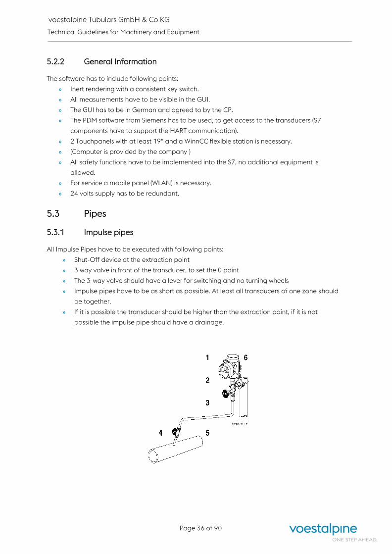
voestalpine Tubulars GmbH & Co KG
Technical Guidelines for Machinery and Equipment
Page 36 of 90
5.2.2 General Information
The software has to include following points:
» Inert rendering with a consistent key switch.
» All measurements have to be visible in the GUI.
» The GUI has to be in German and agreed to by the CP.
» The PDM software from Siemens has to be used, to get access to the transducers (S7
components have to support the HART communication).
» 2 Touchpanels with at least 19“ and a WinnCC flexible station is necessary.
» (Computer is provided by the company )
» All safety functions have to be implemented into the S7, no additional equipment is
allowed.
» For service a mobile panel (WLAN) is necessary.
» 24 volts supply has to be redundant.
5.3 Pipes
5.3.1 Impulse pipes
All Impulse Pipes have to be executed with following points:
» Shut-Off device at the extraction point
» 3 way valve in front of the transducer, to set the 0 point
» The 3-way valve should have a lever for switching and no turning wheels
» Impulse pipes have to be as short as possible. At least all transducers of one zone should
be together.
» If it is possible the transducer should be higher than the extraction point, if it is not
possible the impulse pipe should have a drainage.

voestalpine Tubulars GmbH & Co KG
Technical Guidelines for Machinery and Equipment
Page 37 of 90
5.3.2 Grounding and paintwork
Every pipe, which is not isolated (also impulse pipes) have to be colored correctly. At least 150µm
grounding and 80µm paint is necessary.
Natural gas RAL1018 Air for Ignition burner RAL5021 Air for Main Burner RAL5005
Cooling Air RAL5018 Exhaust/Furnace pressure RAL3020
5.3.3 Pipes for Ignition Burner
The pipes (air and natural gas) for the ignition burner have to be build without connections until the
shut-off device.
5.4 UV-Sensor and Ignition burner
The UV-sensors have to be integrated into the burner that they are not able to see the flame of the
ignition burner or one of the neighbour burners. Our experience of the best possibility is shown in the
graphic. The ignition burner should have at least 10 kW.
5.5 Measurements
5.5.1 Quantity Measurements
All quantity Measurements have to be a temperature and pressure compensated differential
pressure measurement with a restrictor.
5.5.2 Oxygen Measurements
In every zone (logical configurations) and in the exhaust (chimney) an oxygen measurement is
necessary.
5.5.3 Exhaust Measurements
In every chimney a quantity measurement and a temperature measurement is necessary. An
extraction point to check the exhaust should be provided. If the exhaust is pulled back via the burner,
every zone should have a quantity measurement.
UV-Sonde
Ignition-Burner

voestalpine Tubulars GmbH & Co KG
Technical Guidelines for Machinery and Equipment
Page 38 of 90
5.5.4 Pyrometer Measurements
In addition to the mA loop, the serial interface (RS485) or network interface of the pyrometers must
also be routed to a converter so that the pyrometer can be configured via a network connection.
Furnace outlet pyrometers should be mounted as close as possible to the furnace outlet and
equipped with suitable cooling (water). This should reduce the falsification of the outlet temperature.
5.6 Switch cabinets
One Cabinet has to be planed for general part and for each zone a separate cabinet is necessary
(logical configuration e.g. heating zones is possible).
5.7 Limit values
Max. exhaust gas outlet temperature from
the chimney without the addition of fresh
air using a central recuperator or
regenerative burner. In all other cases, the
value should be noted in the project
description.
130 – 200 °C
The max. surface temperatures for the
following points are to be noted in the
project description:
Ceiling
Wall
Insulated cables
Exhaust compounding Austrian Law „Begrenzung der Emission von
luftverunreinigenden Stoffen“, last version
5.8 Thermocouples
The choice of thermocouple must be made in accordance with the contracting party. Thermocouples
of at least one higher grade type must be used.
The temperature ranges are specified in the table below:
From 1200 °C Type B
1000 – 1199 °C Type S
Below 1000 °C Type K
» In addition, it is necessary that the thermocouple offers the possibility of a comparative
measurement.
» The cable on the thermocouples must be left so long that the thermocouple can be pulled out
completely
» A holder for the thermocouple must be provided in the immediate vicinity of the measuring
point

voestalpine Tubulars GmbH & Co KG
Technical Guidelines for Machinery and Equipment
Page 39 of 90
5.9 Cooling of electrical components
All electrical components must be secured in such a way that the electronics are not affected by the
radiant heat.
» Oxygen measurements in the furnace – do not install the electronics on the furnace
» Equip the light sensor with protective plate and protective glass and, if necessary, with water
cooling
5.10 Water cooling on industrial furnaces
If water-cooled dividers monitored by measurements and switches are installed in an industrial
furnace, a bypass line with the necessary shut-off device must be provided at the measurement points
so that replacement or maintenance of the built-in sensors is possible. The furnace must not
immediately lower the furnace temperature or turn off the heating after being triggered by such a
monitoring device.
6 Industrial Computers
The industrial computers have to be sent to the CP for doing a first installation. After this installation
the computer will be send back.
The first installation includes:
» Software
o Virus protection – Office Scan (TrendMicro)
o Remote Maintenance – Fast Viewer (Matrix42)
o Windows 7 64 bit German with actual Windows Patches
o Office 2010
o PDF-XChange Editor
o Hardcopy
o NTP Service
o Empirum Advanced Agent
o End Point Security (Ego Secure)
» User configuration
» Network configuration

voestalpine Tubulars GmbH & Co KG
Technical Guidelines for Machinery and Equipment
Page 40 of 90
Industrial computers and KVM Industrial Computer B&R APC910
- 5PC910.SX02-00
- 5PC900.TS77-00
- 5AC901.HS00-00
- 5MMDDR.8192-03
- 5AC901.FA02-00
- 5AC901.BX02-02
- 5AC901.CSSD-C00
- 54C901.SSCA-00
- 5AC901.FF02-00
- 5AC901.IRDY-00
- 5AC901.ISIO-00
- 0TB2104.8000
- 0TB103.91
- 5SWWI7.1200-GER
2-Slot APC910 System Unit
CPU Board Intel Core i7 3615QE
APC910 Heatsink
RAM SO-DIMM DDR3, 8192 Mbyte
APC910 Fan Kit
APC910 2-Slot BUS – 2x PCI Express (x4)
1 TByte SSD MLC (Slide-In HD) 2x
Front Flap orange
Slide-in compact Adapter
Interface Card Ready Relays
Interface Card System I/O
Plug 24 VDC
Plug 24 VDC
Operating System
KVM Remote Unit IHSE IHSE BE-R477-1SHC
KVM Local Unit IHSE IHSE BE-R477-1SHC
KVM Switch IHSE BE-K480-16C
(Standard)
BE-K480-48C
TCP/IP – Serial
Interface
WuT 58665 Com-Server++
7 APPENDIX A: Electrical parts (approved list) and
documentation specifications
The following lists contain a selection of parts that we prefer to use and that we therefore stock as
spare parts.
Suppliers and manufacturers of electrical equipment are obliged to use the electrical parts in these
lists. Exceptions are allowed when parts from different manufacturers are compatible based on
standards, technical data, size, and connections. When parts are replaced due to a failure, this
cannot result in any changes in the mechanical structure, design, or electrical connections. It also
cannot cause any changes in electrical wiring diagrams
If deviations from this delivery specification are unavoidable, then they must be expressly agreed to
by the CP.
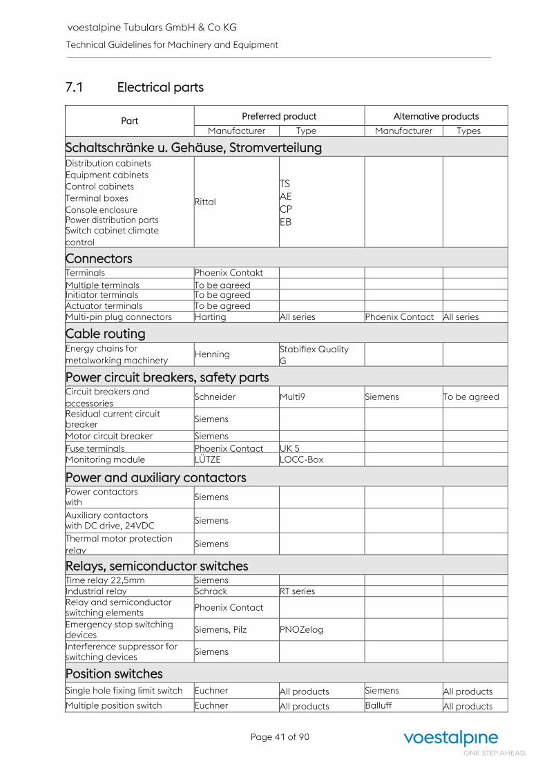
voestalpine Tubulars GmbH & Co KG
Technical Guidelines for Machinery and Equipment
Page 41 of 90
7.1 Electrical parts
Part Preferred product Alternative products
Manufacturer Type Manufacturer Types
Schaltschränke u. Gehäuse, Stromverteilung Distribution cabinets
Equipment cabinets
Control cabinets
Terminal boxes
Console enclosure Power distribution parts Switch cabinet climate
control
Rittal
TS
AE
CP
EB
Connectors Terminals Phoenix Contakt Multiple terminals To be agreed Initiator terminals To be agreed Actuator terminals To be agreed Multi-pin plug connectors Harting All series Phoenix Contact All series
Cable routing Energy chains for
metalworking machinery Henning
Stabiflex Quality
G
Power circuit breakers, safety parts Circuit breakers and
accessories Schneider Multi9 Siemens To be agreed
Residual current circuit breaker
Siemens
Motor circuit breaker Siemens Fuse terminals Phoenix Contact UK 5 Monitoring module LÜTZE LOCC-Box
Power and auxiliary contactors Power contactors with
AC/DC drive
Siemens
Auxiliary contactors with DC drive, 24VDC
Siemens
Thermal motor protection
relay Siemens
Relays, semiconductor switches Time relay 22,5mm Siemens Industrial relay Schrack RT series Relay and semiconductor switching elements
Phoenix Contact
Emergency stop switching devices
Siemens, Pilz PNOZelog
Interference suppressor for switching devices
Siemens
Position switches Single hole fixing limit switch Euchner All products Siemens All products
Multiple position switch Euchner All products Balluff All products

voestalpine Tubulars GmbH & Co KG
Technical Guidelines for Machinery and Equipment
Page 42 of 90
Part Preferred product Alternative products
Manufacturer Type Manufacturer Types
Proximity sensor Proximity sensor, inductive, DC, 24 V M12x1mm pluggable
Balluff BES Euchner All products
Proximity sensor, capacitive, DC, 24 V M12x1mm pluggable
Balluff BES Euchner All products
Proximity sensor, magnetic sensing
(cylinder sensor)
Balluff BMF Sick MZ series
Photoelectric sensors
DC, 24 V
Sick Wenglor Keyence
To be agreed
Safety switches Safety
light curtains
Sick To be agreed
Safety
interface
Sick To be agreed
Control and indicating devices Indicator lights Swisstac Siemens 3SB3
Mushroom pushbutton switch for emergency stop switching devices
Swisstac Siemens 3SB3
Power supplies Single-phase, 230VAC, 24VDC
Phoenix Contact Quint 24V
Three-phase, 380VAC, 24VDC
Phoenix Contact Quint 24V
Text displays and control terminals Displays and control units Siemens To be agreed
Servo-/Frequency converter Frequency converter Siemens Sinamics S120 To be agreed
Safety components Safety switches EUCHNER CET3-AR-CRA-AH
-50..-SG-SG To be agreed
Safety light curtain SICK To be agreed
CNC controllers Drives SIEMENS Sinamics S120 CNC controller SIEMENS 840D sl Control panels SIEMENS To be agreed Machine control panel SIEMENS MCP 483C

voestalpine Tubulars GmbH & Co KG
Technical Guidelines for Machinery and Equipment
Page 43 of 90
Measurement and regulation technology for furnaces
Part Preferred product Alternative products
Manufacturer Type Manufacturer Types
Quantity measurement
Differential pressure
ABB
266CST
Gauge pressure ABB 266GST Differential pressure ABB 266MST Temperature (furnace chamber)
ABB TTF300
Temperature ABB TTR200 Swing drive, large ABB RHD250 (250Nm) Power electronic unit, large ABB EBN 853 Swing drive, small (air and
gas)
ABB PME 120 –
AN (100Nm)
Power electronics, small ABB EAN 823 Safety thermocouple Günther GmbH see 05-99050064-0830 Air and exhaust flaps Jasta GD-6 E/S Drives Flowserve S085D, S100D Burner control unit Kromschröder BCU480-5/3/1LW3GBD2B1/1 UV sensor Kromschröder UVS 10L1G1 Motorized valve for gas Kromschröder VK Solenoid valve for gas Kromschröder VAS, VCS (double solenoid valve) Pressure switches Kromschröder DG…UG Test valve, combustion air Bürkert BA0335-EU Druckregler Kromschröder GDJ High-temperature
monitoring
Jumo
b70.1150.0
Repeater pr electronics 9106B Universal transmitter (To be agreed)
pr electronics 4114
Safety contactors Phoenix Contact PSR-SCP- 24DC/ESP4/2X1/1X2 Safety contactors
(multichannel)
Phoenix Contact
PSR-SCP- 24UC/ESAM4/8X1/1X2
24V redundancy supply Phoenix Contact QUINT-DIODE/12-24DC/2X20/1X40 Contactors Phoenix Contact PR1-RSP3-LDP-24DC/2X21 3 way valve with mounting
accessories
AS-Schneider
S345.06.202.02+S006.38.106. +S006.42.103.04 Oxygen Measurement Oxitec SME5 Oxitec Economy
Key switch
Siemens 3SB3000-3AH01 (high temperature), 3SB3000-
3AG01 (Inert rendering) Mobile Panel Siemens 6AV6645-0DD01-0AX01
Access Point for Mobile
Panel
Siemens
6GK5788-1GD00-0AA0 Pyrometer <700°C Lumasense IMPAC IPE 140/39 MB7 Vario-Optik 3-PE Pyrometer 600 – 1400°C Raytek MR1SASFW

voestalpine Tubulars GmbH & Co KG
Technical Guidelines for Machinery and Equipment
Page 44 of 90
7.2 Selection list of the Phoenix modules
Part Preferred product Alternative products
Manufacturer Type Manufacturer Types
Selection list Phoenix Modules for S7-1500 SCALANCE Switch X208 Siemens 6GK5208-0BA10-2AA3
+ C-Plug Siemens 6GK1900-0AB00
Power supply module PS 60W Siemens 6ES7507-0RA00-0AB0
Repeater RS 485 Siemens 6ES7972-0AA02-0XA0
Act. RS485 termination
element Siemens 6ES7972-0DA00-0AA0
Central module CPU 1517F-3
PN/DP Siemens 6ES7517-3FP00-0AB0
+ SIMATIC Memory Card 12
MB Siemens 6ES7954-8LE02-0AA0
Communication proc. CP
1543-1 Siemens 6GK7543-1AX00-0XE0
Interface module IM 155-6 PN
HF Siemens 6ES7155-6AU00-0CN0
+ BusAdapter BA 2×RJ45 Siemens 6ES7193-6AR00-0AA0
Digital input module F-DI
8x24VDC HF Siemens 6ES7136-6BA00-0CA0
+ BaseUnit BU15-P16+A0+2D Siemens 6ES7193-6BP00-0DA0
Digital input module DI
16x24VDC ST Siemens 6ES7131-6BH00-0BA0
+ BaseUnit BU15-
P16+A10+2D Siemens 6ES7193-6BP20-0DA0
Digital output module F-DQ
4x24VDC HF Siemens 6ES7136-6DB00-0CA0
+ BaseUnit BU15-P16+A0+2D Siemens 6ES7193-6BP00-0DA0
Digital input module DI
32x24VDC HF Siemens 6ES7521-1BL00-0AB0
+ Front plug-in module for 4 x
8 I/O Siemens 6ES7921-5AH20-0AA0
+ 4 pcs. round cable Phoenix FLK 14/16/EZ-DR/
200/S7
Digital output module DQ
32x24VDC ST Siemens 6ES7522-1BL01-0AB0
+ Front plug-in module for 4 x
8 I/O Siemens 6ES7921-5AH20-0AA0
+ 4 pcs. round cable Phoenix FLK 14/16/EZ-DR/
200/S7

voestalpine Tubulars GmbH & Co KG
Technical Guidelines for Machinery and Equipment
Page 45 of 90
Part Preferred product Alternative products
Manufacturer Type Manufacturer Types
VARIOFACE transfer module Phoenix VIP-2/PT/FLK14/PLC
V8-OUTPUT-Adapter Phoenix PLC-V8/FLK14/OUT
+ 8 pcs. relay modules Phoenix PLC-RPT- 24DC/21
V8-OUTPUT-Adapter Phoenix PLC-V8/FLK14/OUT
+ 8 pcs. solid state relay
modules
Phoenix PLC-OPT- 24DC/
24DC/2
Patch panel RJ45-LSA Phoenix FL-PP-RJ45-LSA
7.3 TIA approved list
Part Preferred product Alternative products
Manufacturer Type Manufacturer Types
TIA Portal approved assemblies for VAT dated 25 July 2017 Digital input module. DI
8x24VDC ST Siemens
6ES7 131-6BF00-0AB0
ET200SP 8xDI
Digital input module DI
16x24VDC ST Siemens
6ES7 131-6BH00-0AB0
ET200SP 16xDI
Digital output module, DQ 8x
24VDC/0,5A ST Siemens
6ES7 132-6BF00-0AB0
ET200SP 8xDO
Digital output module DQ
4x24VDC/ 2A ST Siemens
6ES7 132-6BD20-0AB0
ET200SP 4xDO 2A
Digital output module. DQ
16x24VDC/0.5A ST Siemens
6ES7 132-6BH00-0AB0
ET200SP 16xDO
Analog input module. AI
4xU/I 2-wire ST Siemens
6ES7 134 6HD00-0BA1
ET200SP 4xAI U/I 2-wire
Analog input module. AI
2xU/I 2-wire ST Siemens
6ES7 134 6HB00-0BA1
ET200SP 2xAI U/I 2-wire
Analog input module. AI 4xI 2-
/4-wire ST Siemens
6ES7 134 6GD00-0BA1
ET200SP 4xAI 4-wire
Analog output module AQ 4xU/I
ST Siemens
6ES7 135 6HD00-0BA1
ET200SP 4xAO U/I ST
Digital input module F-DI
8x24VDC HF Siemens
6ES7 136-6BA00-0CA0
ET200SP 8xF-DI
Digital output module F-DQ
4x24VDC/ 2A PM HF Siemens
6ES7 136-6DB00-0CA0
ET200SP 4xF-DO
1x 24V counter module,
1 channel for 24V incremental Siemens
6ES7 138-6AA00-0AB0
TM Count 24V
Technology module TM Pulse 2x
24V PWM and pulse output, 2
channels 2A
Siemens 6ES7 138-6DB00-0BB1
TM Pulse 2x24V
Interface-Module
IM 155-5 PN HF Siemens
6ES7 155-5AA00-0AC0
ET200MP IM155-5 PN HF

voestalpine Tubulars GmbH & Co KG
Technical Guidelines for Machinery and Equipment
Page 46 of 90
Part Preferred product Alternative products
Manufacturer Type Manufacturer Types
Interface-Module
IM 155-6 PN ST Siemens
6ES7 155-6AU00-
0BN0 ET200SP IM155-
6 PN ST
Interface-Module
IM 155-6 PN HF Siemens
6ES7 155-6AU00-
0CN0 ET200SP IM155-
6 PN HF
PN/PN coupler Siemens 6ES7 158-3AD01-
0XA0 PN/PN Coupler
Bus adapter BA 2xRJ45, 2
RJ45 sockets for PROFINET Siemens
6ES7 193-6AR00-0AA0
ET200SP Profinet
interface
Base-unit BU15-P16+A0+2B,
BU-Type A0, push-in
terminals, without ...
Siemens
6ES7 193-6BP00-0BA0
ET200SP Base-unit
type A bridged to the
left without AUX
Base-unit BU15-P16+A0+2D,
BU-Type A0, push-in
terminals, without ...
Siemens
6ES7 193-6BP00-0DA0
ET200SP Base-unit
type A new load group
without AUX
Base-unit BU15-
P16+A10+2B, BU-Type A0,
push-in terminals, with 10 ...
Siemens
6ES7 193-6BP20-0BA0
ET200SP Base-unit
type A bridged to the
left with 10 AUX
Base-unit BU15-
P16+A10+2D, BU-Type A0,
push-in terminals, with 10 ...
Siemens
6ES7 193-6BP20-0DA0
ET200SP Base-unit
type A new load group
with 10 AUX
Server module for ET 200SP Siemens
6ES7 193-6PA00-0AA0
ET200SP Server
module
Power supply module PS
60W. 120/230V AC/DC Siemens
6ES7 507-0RA00-0AB0
PS 60W
Central module with 200 KB
main memory for program
and 1Mbyte for data, 1.
Interfaces: PROFINET IRT with
3 Port Switch, 48 NS Bit-
Performance, SIMATIC
Memory Card required, Bus
adapter required for ports 1
and 2
Siemens 6ES7 512-1DK01-0AB0
CPU1512SP-1 PN
Central module with 300 KB
main memory for program
and 1Mbyte for data, 1.
Interfaces: PROFINET IRT with
3 Port Switch, 48 NS Bit-
Performance, SIMATIC
Memory Card required, Bus
adapter required for ports 1
and 2
Siemens
6ES7 512-1SK01-0AB0
CPU1512SP F-1 PN F-
CPU

voestalpine Tubulars GmbH & Co KG
Technical Guidelines for Machinery and Equipment
Page 47 of 90
Part Preferred product Alternative products
Manufacturer Type Manufacturer Types
Central module with 1MByte
main memory for program and
5Mbyte for data, 1. Interfaces:
PROFINET IRT with 2-port switch,
2. Interfaces: PROFINET RT, 3.
Interfaces: PROFIBUS, 10 NS Bit
performance, SIMATIC Memory
Card required
Siemens 6ES7 516-3AN01-0AB0
CPU1516
Central module CPU 1517F-3
PN/DP Siemens
6ES7 517-3FP01-0AB0
FCPU1517
Digital input module DI
32x24VDC HF Siemens
6ES7 521-1BL00-0AB0
DI32
Digital output module. DQ
32x24VDC/0.5A ST Siemens
6ES7 522-1BL00-0AB0
DO32
Digital input / output module. DI
16x24VDC/
DQ 16x24VDC/0.5A BA
Siemens
6ES7 523-1BL00-0AA0
DI 16/DQ
16x24CDC/0.5A BA_1
Analog input module AI
8xU/I/RTD/TC ST Siemens
6ES7 531-7KF00-0AB0 AI
8xU/I/RTD/TC ST
Analog input module AI
4xU/I/RTD/TC ST Siemens
6ES7 531-7QD00-0AB0
AI 4xU/I/RTD/TC ST
Analog output module AQ 4xU/I
ST Siemens
6ES7 532-5HD00-0AB0
AO 4xU/I ST
Analog output module AQ 8xU/I
HS Siemens
6ES7 532-5HF00-0AB0
AO 8xU/I ST
Analog output module AQ 2xU/I
ST Siemens
6ES7 532-5NB00-0AB0
AO 2xU/I ST_1
Front connector with push-in
technology, 40-pole, for 35mm
width assemblies incl. 4 potential
bridges and ...
Siemens 6ES7 592-1BM00-0XB0
front connector 40pol
Front plug-in module with 4x16
pol. IDC connection for digital 32
I/O modules of the S7-1500 ...
Siemens
6ES7 921-5AH20-0AA0
front plug-in module
4x16
Memory Card fur S7-1x 00
CPU/SINAMICS, 3, 3V Flash, 12
MByte.
Siemens
6ES7 954-8LE02-0AA0
MEM CARD 12MB for
CPU15xx
C-Plug/Memory Card Siemens 6GK1 900-0AB00 C-Plug
Card for Scalance
IRT switch, 4x 10/100 Mbit/s
RJ45 ports, fault signalling
contact with set button,
redundant power supply, ...
Siemens 6GK5 204-0BA00-2BA3
Scalance X204 IRT
IE switch, 8x 10/100 Mbit/s RJ45
ports, fault signalling contact
with set button, ...
Siemens 6GK5 208-0BA00-2AF2
Scalance XF208
IE switch, 8x 10/100 Mbit/s RJ45
ports, LED diagnosis, fault
signalling contact with ...
Siemens 6GK5 208-0BA10-2AA3
Scalance X208
IWLAN Access Point Siemens
6GK5 788-2GD00-0AA0
Scalance W788-2
Wireless LAN

voestalpine Tubulars GmbH & Co KG
Technical Guidelines for Machinery and Equipment
Page 48 of 90
Part Preferred product Alternative products
Manufacturer Type Manufacturer Types
Communication processor Siemens
6GK7 543-1AX00-0XE0
Communication proc.
Ethernet
Comfort Panel, touch control, ... Siemens 6AV2 124-0GC01-0AX0
TP700 7"
Comfort Panel, touch control, ... Siemens 6AV2124-0JC01-0AX0
TP900 9"
Comfort Panel, touch control, ... Siemens 6AV 2124-0MC01-0AX0
TP1200 12"
Comfort Panel, touch control, ... Siemens 6AV2 124-0QC02-0AX0
TP1500 15"
Protective foil 7” wide screen for
KTP700 Basic Siemens
6AV2 124-6GJ00-0AX0
protective film 7” wide
screen
Protective foil 15” wide screen
for KTP700 Basic Siemens
6AV2 124-6QJ00-0AX1
protective film 15” wide
screen
HMI memory card 2 GB Siemens 6AV2 181-8XP00-0AX0
HMI SD 2GB
HMI connection box Siemens
6AV2 125-2AE23-0AX0
advanced connection
box
HMI Mobile Panel
7.0" TFT-Display Siemens
6AV2 125-2GB23-0AX0
KTP700F Mobile Panel 7"
Mobile Panel 277
with confirmation button and
STOP button
Siemens 6AV6 645-0CB01-0AX0
Mobile Panel 277 8"
Connection cable PN for Mobile
Panels (PROFINET)
Length 5m
Siemens 6XV1 440-4BH50 cable
for PN (4MAA, 4TGA)
Connection box PN plus for
Mobile Panels (PROFINET). Siemens
6AV6 671-5AE11-0AX0
connection box PN
(4MAA, 4TGA)
Charging station for
Mobile Panel 277(F) IWLAN Siemens
6AV6 671-5CE00-0AX1
Charging station for
Mobile Panel 277
Main battery 7.2V for
Mobile Panel 277 IWLAN, Mobile
Panel 277F IWLAN,
Siemens
6AV6 671-5CL00-0AX0
main battery for Mobile
Panel 277
Protective foil 8” touch devices,
type 10, for Mobile Panel 277 8" Siemens
6AV6 671-5BC00-0AX0
protective foil for 8"
Mobile Panel
Mobile Panel 277F IWLAN (RFID),
with integrated confirm /
emergency stop button, hand
wheel, key switch and two
illuminated pushbuttons
Siemens
6AV6 645-0EF01-0AX1
Mobile Panel 277F 8"
IWLAN
Measuring instrument
7KM PAC3200, optional Modbus
RTU / PROFINET / PROFIBUS,
apparent / active / reactive
energy
Siemens 7KM2111-1BA00-3AA0
Sentron PAC 3200

voestalpine Tubulars GmbH & Co KG
Technical Guidelines for Machinery and Equipment
Page 49 of 90
7.4 Documentation requirements
For EPLAN, the VAT sample project and base project are to be used, which are also stored in the
download section.
VAT standard for terminal blocks and cable labelling
Terminal
block
diagram
Condu
ctor
colours
Description Description Cable
labelling Manual
-XD0 -
XD99 BK
Voltage level
400VAC
Supplies, motor outgoing
feeders, etc. W1-W99
Number ranges,
expand to. E.g.
W99.1 and
W99.2 for
motors with
brakes,
encoders, 2
directional
motors, forced
cooling fans
.1 for first
direction of
rotation
(rotational
speed)
-XD100 -
XD199 YE, BU Safety technology
Sensors, e.g. emergency
stop, light curtains.
ATTENTION: the actuators
are to be drawn in relation
to their voltage!
All leads for safety-
relevant functions are
yellow. E.g. leads that are
connected to F-modules
or safety circuits of safety
switchgear. Feedbacks
routed to standard inputs
must be wired blue.
W101-W199
Expand number
ranges if two or
more cables
lead to one
electrical device.
E.g. W199.1 and
W199.2
-XD200 -
XD299 RD
Voltage level
230VAC W201-W299
Expand number
ranges if two or
more cables
lead to one
electrical device.
E.g. W299.1 and
W299.2
-XD300 -
XD349 GN
Voltage level
< 230VAC W301-W399
Expand number
ranges if two or
more cables
lead to one
electrical device.
E.g. W499.1 and
W499.2

voestalpine Tubulars GmbH & Co KG
Technical Guidelines for Machinery and Equipment
Page 50 of 90
Terminal
block
diagram
Condu
ctor
colour
s
Description Description Cable
labelling Manual
-XD350 -
XD399
YE,
GN,
BU,
RD,
BN,
WH,
BK,
YE/G
N
400VAC/230VAC/
24VDC...
For special cables with
different voltage levels
(e.g. for servomotors ...)
W301-W399
Expand number
ranges if two or
more cables
lead to one
electrical device.
E.g. W499.1 and
W499.2
-XD400 -
XD499 BN
Control voltage up
to 220VDC (except
24VDC)
W401-W499
Expand number
ranges if two or
more cables
lead to one
electrical device.
E.g. W299.1 and
W299.2
-XD500 -
XD599 BU
Voltage level 0-
24VDC (including
digital signals)
Supplies, signals, sensors,
actuators W501-W599
Expand number
ranges if two or
more cables
lead to one
electrical device.
E.g. W599.1 and
W599.2
-XD600 -
XD699
Reserve for later
use
-XF700 -
XF799
Network cable
(Ethernet)
Operating computer,
SASI, Video LAN,
connections between the
controllers
W701-W799
-XF800 -
XF899 Fieldbus cable
Profibus, Profinet,
Modbus, DALI ... W801-W899
-XG900 -
XG999
WH,
BU
Analog values and
encoder signals
Analog signals, encoders
(absolute value, resolver,
incremental encoder ...),
thermistors, PTC, NTC, KTY
...
W901-W999
Expand number
ranges if two or
more cables
lead to one
electrical device.
E.g. W999.1 and
W999.2
-XE YE/G
N
Ground and shield
terminals
For terminal blocks that
are used exclusively for
earthing or shielding
function.

voestalpine Tubulars GmbH & Co KG
Technical Guidelines for Machinery and Equipment
Page 51 of 90
8 APPENDIX B: voestalpine Tubulars S7 software
specifications
8.1 Liability disclaimer
The authors have taken every care to publish complete and accurate information in this user manual
and any other accompanying information media. The authors neither guarantee nor assume legal
liability for the use of this information, its economic viability or error-free function for a specific
purpose. Moreover, the authors accept no liability for damages, for any misinterpretation of the
content, nor for any resulting violation of patent rights and other titles of third parties.
8.2 Hardware configuration / device view
The equipment and safety functions are generally executed on an S7-1500 CPU 1517F-3 PN/DP
(1517-3FP00-0AB0):
Any data exchange with other controllers may be implemented via a separate network based on
ProfiNet (I-Device) or via PN/PN coupler.
For ProfiNet networks, a topology must be created in order to make it easier for maintenance to
replace the device in the event of a fault:

voestalpine Tubulars GmbH & Co KG
Technical Guidelines for Machinery and Equipment
Page 52 of 90
8.3 Structuring
8.3.1 Programming languages and standard software
The standard programming language function block diagram (FBD) from the TIA Portal must
preferably be used. The representation in statement lists (STL) and ladder diagrams (LAD) is not
allowed.
For complex problems, the programming language SCL is allowed. A GRAPH sequence must be used
for configuring and programming sequential processes with sequence cascades, e.g. sequences for
automatic processes. Only the use of the WinCC-Advanced configuration software from the TIA Portal
is required to configure the user menus for the touch panels.
Exceptions are allowed only when absolutely necessary and only with the express agreement of the CP.
The versions of the programming tools are to be agreed with the CP.
8.3.2 Program structure
The programming tools’ features are to be used to develop clear, structured PLC programs, especially
for functional block diagrams (FBDs). To promote clearly structured programming, the same operands
should not be used for assignment, set, and reset operations. The program structure is to be agreed
with the CP.
All global variables (inputs, outputs, flags, data points, etc.) are to be clearly labelled according to their
function. All block headers and networks are to be given comments on their use. Complex functions
must be verbally described in the block to make them easier for service personnel to understand. All
drive-related functions must be implemented with simple logic without using function blocks.
Functions that were not included in this document or in the example project are to be agreed with the
CP.

voestalpine Tubulars GmbH & Co KG
Technical Guidelines for Machinery and Equipment
Page 53 of 90
8.3.3 Folder structure
An overview structure for folders and groupings is to be used:
8.3.3.1 00_Fehler_OB
The required error OB is stored here (“Rack or station failure”, ...)
8.3.3.2 01_Standardbausteine
Standard blocks may only be used for general, recurring functions (NOT for drives):

voestalpine Tubulars GmbH & Co KG
Technical Guidelines for Machinery and Equipment
Page 54 of 90
8.3.3.3 05_Sicherheitsprogramm
8.3.3.3.1. 01_Allgemein
» FB “F_Allgemein”: Safety program, general
» DB “Sicherheit_DB”: Safety data block
8.3.3.3.2. 02_Not_Halt
For each emergency stop, an FB is created here in which the signals are processed.
8.3.3.3.3. 03_Schutztueren
For each safety door, an FB is created here in which the signals are processed.
8.3.3.3.4. 04_Lichtgitter
For each light grid, an FB is created here in which the signals are processed.
8.3.3.3.5. 05_Sonstige_Signale
For all other clear signals, an FB is created here in which the signals are processed.
8.3.3.3.6. 10-99 Safety circuits
The safety circuits / drives are stored in groups depending on the structure of the safety concept
(drive or safety circuit related). If the safety concept is drive related, the grouping must be the same
as the equipment areas in the standard program. An FB is created for each safety circuit or drive
(e.g. ProfiSafe).

voestalpine Tubulars GmbH & Co KG
Technical Guidelines for Machinery and Equipment
Page 55 of 90
8.3.3.4 10_Allgemein
» FC “Allgemein”: General functions
» FC “Allgemein_xxx”: Own FC per controller console for general functions
» FC “Austausch_xxx”: Own FC per controller with which data is exchanged
» FC “Busfehler”: Calling the “DeviceStates” function for each bus system
» FC “Datenaufb_HMI”: Data preparation for HMI (counters, light barriers, …)
» FC “Materialverfolgung”: Material tracking (walking beam allocation, pipes in
tester, ...)
» FB “Analog”: Analog value processing
» DB “Analog_DB”: Analog values (if analogue values available)
» DB “Antriebe_DB”: Drives (if visualization necessary)
» DB “Betriebsstunden_DB”: Operating hours (if required)
» DB “Datum_Zeit_DB”: Date and time
» DB “HMI_DB”: Data for HMI (one DB per HMI device)
» DB “Materialverfolgung_DB”: Data for material tracking (if required)
» DB “Multimessgeraet_DB”: Data from the system power supplies (PAC3200)
» DB “RACK_FLT_DB”: Profibus failures
» DB “Rampenbildner_DB”: Ramp generator (if proportional valves available)
» DB “Regler_DB”: Controller (if needed)
8.3.3.5 11-19 Sonstige Allgemeine Ordner
e.g.: Safety doors, Allgemein_Sinamics, ...
8.3.3.6 21-89 Anlagenbereiche
A folder is created for each equipment or operating area (in the material flow direction):

voestalpine Tubulars GmbH & Co KG
Technical Guidelines for Machinery and Equipment
Page 56 of 90
Each area contains the operating mode and the drive functions:
In case it is required for clarity purposes, it is also necessary to subdivide material tracking from
equipment areas, so that a block is created for each area. In this example, it would be FC
“5TRA010_01_Materialverfolgung”. The “Materialverfolgung” block in the “10_Allgemein” folder is
then omitted.
8.3.3.7 91_Betriebsrechner
Here all signals for the higher-level master computer are generated in the “Betriebsrecher” FC. These
are stored in the “Betriebsrechner_DB” DB.
This DB must not be set to “optimierter Bausteinzugriff” because the “WinCC OA” master computer
cannot access symbolic operands. Furthermore, the option “Zugriff über PUT/GET-Kommunikation
durch entfernte Partner erlauben” must be set in the hardware configuration of the CPU.
8.3.3.8 99_Meldungen
» FC “Betriebsmeldungen”: Operating messages (No start possible: …)
» FC “STOER”: Enter general fault messages Drive related messages
o are recorded directly in the drive block
» FB “STOERAUS”: Evaluate error messages (new error, horn)
» DB “Meld_HMI_xxx:DB”: Error messages for HMI (one DB per HMI device)
» DB “Meld_PVSS_DB”: Error messages for electrical fault indicator (PVSS/WinCC-OA)
» DB “STOER_DB”: Fault messages / operating messages
The DB for WinCC-OA must not be set to “optimierter Bausteinzugriff” because this system cannot
access symbolic operands. Furthermore, the option “Zugriff über PUT/GET-Kommunikation durch
entfernte Partner erlauben” must be set in the hardware configuration of the CPU.

voestalpine Tubulars GmbH & Co KG
Technical Guidelines for Machinery and Equipment
Page 57 of 90
8.4 PLC variables
The program logic is handled by flags (not via DB or instances), so that program changes can be
imported at any time during operation, without shutting down the system for loading and reinitializing
(instance) data blocks!
The PLC variables are created in the following, separate variable tables:
» 00_Ausgaenge
» 00_Ausgaenge_Analog
» 00_Ausgaenge_FU
» 00_Eingaenge
» 00_Eingaenge_Analog
» 00_Eingaenge_FU
» 00_PNPN
» 05_Parameter_Sicherheitsprogramm
» 10_Allgemein
» 11-19 Sonstige Allgemeine Variablen
» 21-89 Variablen Anlagenbereiche
» 91_Betriebsrechner
» 98_Ueberbrueckungsmerker
» 99_Weiß_ich_noch_nicht
The names of these variables tables correspond with the folder names in the program blocks and also
contain the variables of these folders.
e.g.: In the variables table “21_Trsp_vor_KBA” the variable from the blocks are in the folder
“21_Trsp_vor_KBA”.

voestalpine Tubulars GmbH & Co KG
Technical Guidelines for Machinery and Equipment
Page 58 of 90
8.4.1 Input / output variables
The symbol must contain the following information:
» “E_” or “A_”
» Equipment / drive code
» Part
The comment must contain the following information:
» Location code
» Equipment / drive code
» Part
» Type:
o SM…error message
o K ...contactor / relay
o Y...valve
o QS...transverse signal
o BE...Bero switch
o ES...limit switch
o LS...light barriers
o P...pressure switch
o Q...flow switch
o L...level switch
o DT...pushbuttons
o LDT…illuminated pushbuttons
o LDS...illuminated push switches
o PDTV…locked mushroom pushbuttons
o ML...signal lamp
o H...horn / summer
o SS…rotary switch
o SSS…rotary switch with key
o STZ…safety door (locking device)
o SLG…safety light grid
o SLV…safety light curtain
o SLS...safety light barrier
o SQS...safety transverse signal
o SES...safety limit switch
o …
» Text
Examples of symbols and comments:
E_5TRA021-FC11
+5S2E104 =5TRA.021-FC11 SM dispensing trough 1 chain drive motor error

voestalpine Tubulars GmbH & Co KG
Technical Guidelines for Machinery and Equipment
Page 59 of 90
E_5TRA027-BG202
+5TRA.027 =5TRA.027-BG202 BE flap transfer lowered to AM 1
E_5TRA021-SF11
+5ST1P02 =5TRA.021-SF11 LDT dispensing trough 1 lift chain drive
8.4.2 FU input / output variables / other fieldbus devices
Variables for fieldbus devices are always defined using data types.
e.g. FU PPO type 4:
This enables direct access to the status and control values, without having to use various send and
receive blocks (DPRD_DAT, DPWR_DAT SFC14 / SFC15 for Simatic S7-300/400).
The same applies to variables in connection with a data exchange with another controller.

voestalpine Tubulars GmbH & Co KG
Technical Guidelines for Machinery and Equipment
Page 60 of 90
8.4.3 Flag assignment: general
Here it is evident that in the hardware configuration, the clock flag byte is set to 0 and the system flag
byte is set to 1.
The start-up flags are used to easily find (using cross-references) everything that had to be bridged /
blocked during start-up.

voestalpine Tubulars GmbH & Co KG
Technical Guidelines for Machinery and Equipment
Page 61 of 90
An acknowledgment flag is created for each equipment area.
The following variables are defined for each control voltage range:
» Acknowledgment pulse (e.g. for acknowledgment FU use)
» Delayed control voltage on / off
» General approval
Variables for lamp test and screen blanking are defined for each control console.
The dark switching is linked to each signal lamp directly in front of the output and has the purpose of
dark switching the whole control panel with a flag. This flag is generally generated with the key switch
“Control voltage on”.
8.4.4 Flag assignment: operating mode
As shown in the screenshot, always first add the name of the area and then describe the function in the
comment in order to have a better overview see the red border line.
The same applies to the symbol (Nummer_Funktion) see the blue border line.
8.4.5 Flag assignment: drive
Example of 2-direction drive:
As shown in the screenshot, always first add the name of the drive and then describe the function in the
comment in order to have a better overview see the red border line.
The same applies to the symbol (Antriebsnummer_Funktion) see the blue border line.
For flexibility reasons, end positions are always set on flags in case, for example, the sensor is linked
differently (normally closed, normally open contact, exchange with analogue sensor, ...).

voestalpine Tubulars GmbH & Co KG
Technical Guidelines for Machinery and Equipment
Page 62 of 90
Example FU:
8.4.6 Bypass Flag
Here, flags are defined with which various functions are deactivated.
Examples:
» Temporary bypass of a defective sensor
» Preparations for a future conversion
» Tests performed by the production department
These flags make it possible to quickly find changes via cross-reference. In addition, a textual
description is stored in the comment of the flag.
8.4.7 “Don’t know yet”
The “Don’t know yet ...” signals are to be used for open points to make them easy to find.
8.4.8 Parameters
For fixed parameters in the equipment, the possible “user constants” in the TIA Portal must be used.
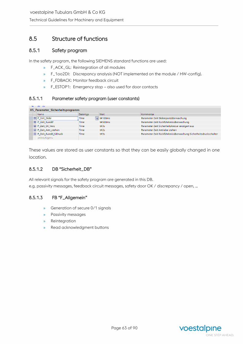
voestalpine Tubulars GmbH & Co KG
Technical Guidelines for Machinery and Equipment
Page 63 of 90
8.5 Structure of functions
8.5.1 Safety program
In the safety program, the following SIEMENS standard functions are used:
» F_ACK_GL: Reintegration of all modules
» F_1oo2DI: Discrepancy analysis (NOT implemented on the module / HW-config).
» F_FDBACK: Monitor feedback circuit
» F_ESTOP1: Emergency stop – also used for door contacts
8.5.1.1 Parameter safety program (user constants)
These values are stored as user constants so that they can be easily globally changed in one
location.
8.5.1.2 DB “Sicherheit_DB”
All relevant signals for the safety program are generated in this DB.
e.g. passivity messages, feedback circuit messages, safety door OK / discrepancy / open, …
8.5.1.3 FB “F_Allgemein”
» Generation of secure 0/1 signals
» Passivity messages
» Reintegration
» Read acknowledgment buttons

voestalpine Tubulars GmbH & Co KG
Technical Guidelines for Machinery and Equipment
Page 64 of 90
8.5.1.4 Emergency Stop FB “NH_xxx”
Reading all emergency stops with F_1oo2DI discrepancy analysis in each corresponding FB:

voestalpine Tubulars GmbH & Co KG
Technical Guidelines for Machinery and Equipment
Page 65 of 90
8.5.1.5 Safety doors FB “T_xxx”
Reading all safety doors with F_1oo2DI discrepancy analysis in each corresponding FB:
8.5.1.6 Light grid / light curtain FB “LS_xxx”
Reading all light grids / light curtains F_1oo2DI discrepancy analysis and acknowledgment with
F_ESTOP1 in each corresponding FB:
8.5.1.7 Other safety signals FB904
Reading all other safety signals with F_1oo2DI discrepancy analysis in each corresponding FB:
8.5.1.8 Safety circuits FB “SK_xxx”
Safety-related functions in the following sequence:
» Safety circuit OK
» Acknowledge / release safety circuit
» Relay or Profisafe-Bits
» Monitor feedback circuit

voestalpine Tubulars GmbH & Co KG
Technical Guidelines for Machinery and Equipment
Page 66 of 90
Example of safety circuit with F output:
Example of Profisafe FU (drive HO task chain conveyor 1):
8.5.2 General
8.5.2.1 FC “Allgemein”
The following signals are generated in the FC:
» Start-up flag 0/1
» Timing pulses
» Control voltage range x on
» Error acknowledgment buttons are placed on flags or acknowledgment pulses are
generated
» Lamp tests for each operating console are placed on flags
» “Screen blanking” is generated for each operating console e.g. with key switch control
voltage for all lamps, these flags will be connected such that nothing lights up when the
equipment is off.
» Date / time will be read from PLC

voestalpine Tubulars GmbH & Co KG
Technical Guidelines for Machinery and Equipment
Page 67 of 90
8.5.2.2 FC “Allgemein_xxx”
Own FC per operating console for general functions / signalling:

voestalpine Tubulars GmbH & Co KG
Technical Guidelines for Machinery and Equipment
Page 68 of 90
8.5.2.3 FC “Austausch_xxx”
Own FC per controller with which data is exchanged:
8.5.2.4 FC “Datenaufb_HMI”
Signals that were stored in a DB for the HMI:
» Counter preparation (piece counter, good / bad pipe counter, …)
» Sensors for displaying on overview display
» Safety doors / safety light grids for displaying on overview display
» Target values from HMI
» …
8.5.2.5 FC “Materialverfolgung”
Generation of signals for material tracking.
e.g.:
» Location of good / bad pipes
» Detection and marking of pipe faults
» …
Material tracking is then processed collectively, e.g. in the FC “pipe tracking” in SCL.

voestalpine Tubulars GmbH & Co KG
Technical Guidelines for Machinery and Equipment
Page 69 of 90
8.5.2.6 FB “Analog”
All analogue inputs are scaled here.
8.5.2.7 FC for calculations, pipe tracking
Complex calculations and material logistics with large data structures are processed in SCL.
8.5.2.8 Profibus / Profinet error evaluation
Is realized with the function “DeviceStates”:
8.5.3 Equipment areas
8.5.3.1 FC “xxx_Betriebsart”
All functions for the given automatic area:
» Automatic start conditions
» Automatic off
» Automatic pre-selection
» Automatic on / off
» Manual pre-selection
» Operating mode: manual
» Various pre-selections and program modes
» All drives started automatically
» Calling up GRAPH step processes
» Signalling
» Sum error

voestalpine Tubulars GmbH & Co KG
Technical Guidelines for Machinery and Equipment
Page 70 of 90
8.5.3.2 Drives
Drive-related functions:
Example of 2-direction drive:

voestalpine Tubulars GmbH & Co KG
Technical Guidelines for Machinery and Equipment
Page 71 of 90
Example of FU:

voestalpine Tubulars GmbH & Co KG
Technical Guidelines for Machinery and Equipment
Page 72 of 90
Example of valve:
8.5.4 Messages
8.5.4.1 FC “Betriebsmeldungen”
Generation of messages that keep a machine / automation from starting.
e.g.:
» No start possible: Walking beams not in starting position
» Feeding not enabled
» Hydraulic device not on
» …
8.5.4.2 FC “STOER”
Generation of general fault messages Drive-related messages are generated directly in the drive
block.

voestalpine Tubulars GmbH & Co KG
Technical Guidelines for Machinery and Equipment
Page 73 of 90
8.5.4.3 FB “STOERAUS”
This evaluates which messages have arrived or which have not yet been acknowledged.
For this, the data type “STOER_Typ” is used repeatedly (current / old / edges / not acknowledged
messages) in the static interface.
In addition, the messages are routed in the direction of WinCC-OA and TPs.
Furthermore, event messages of type “BM_Typ” are also declared here.
8.5.4.4 DB “STOER_DB”
The error message DB is the instance DB of FB “STOERAUS” and contains operating and error
messages of the data type “BM_Typ” or “STOER_Typ”.
The error message type is to be set up similar to the symbols:
This error message DB will be entered in a central error message system.
8.6 PLC data types
The same folder names as in the PLC program are again also found in the PLC data types:
8.6.1 Safety data type: Not_Halt

voestalpine Tubulars GmbH & Co KG
Technical Guidelines for Machinery and Equipment
Page 74 of 90
8.6.2 Safety data type: Schutztuer_ohne_Anford_entr
Required if safety door lock is triggered with standard output.
8.6.3 Safety data type: Schutztuer_mit_Anford_entr
Required if safety door lock is triggered with safe output.
8.6.4 Safety data type: Lichtgitter
8.6.5 Safety data type: F_Signal_Allgemein
8.6.6 Safety data type: Sicherheitskreis_ohne_RUECKF
8.6.7 Safety data type: Sicherheitskreis_mit_RUECKF

voestalpine Tubulars GmbH & Co KG
Technical Guidelines for Machinery and Equipment
Page 75 of 90
8.6.8 Drive
Only required if drives are visualized in detail on the factory visualization of type WinCC-OA.
In this case, VAT provides an Excel list in which all drives with DB number and offset are entered and
provided with additional information. E.g.: Which alarm is displayed in the detail screen or which text
have the used free alarms, ...
8.6.8.1 Antrieb_Status_Typ
8.6.8.2 Antrieb_Befehle_Typ
8.6.8.3 Antrieb_Alarme_Typ

voestalpine Tubulars GmbH & Co KG
Technical Guidelines for Machinery and Equipment
Page 76 of 90
8.6.8.4 Antrieb_Typ
8.6.9 Analogwerte_Typ
8.6.10 Rampenbildner_Typ

voestalpine Tubulars GmbH & Co KG
Technical Guidelines for Machinery and Equipment
Page 77 of 90
8.6.11 Regler_Typ

voestalpine Tubulars GmbH & Co KG
Technical Guidelines for Machinery and Equipment
Page 78 of 90
8.6.12 Betriebsstundenzaehler_Typ
8.6.13 Mittelwert_Typ
8.6.14 RACK_FLT_Typ
8.6.15 Antrieb FU PPO4 (z.B. PDrive)
8.6.15.1 PDrive_PPO4_RCV_Typ:

voestalpine Tubulars GmbH & Co KG
Technical Guidelines for Machinery and Equipment
Page 79 of 90
8.6.15.2 PDrive_PPO4_SND_Typ:
8.6.15.3 PDrive_PPO4_Istwerte_Typ:
8.6.16 Sinamics
8.6.16.1 Sinamics_Einspeisung
8.6.16.1.1. Sinamics_Einsp_T371_08W_RCV_Typ (Starter Standardtelegramm 371)

voestalpine Tubulars GmbH & Co KG
Technical Guidelines for Machinery and Equipment
Page 80 of 90
8.6.16.1.2. Sinamics_Einsp_T371_05W_SND_Typ (Starter Standardtelegramm 371)
8.6.16.1.3rd Sinamics_Einsp_Istwerte_Typ
8.6.16.1.4th Sinamics_Einsp_Typ
Only required if drives are visualized in detail on the factory visualization of type WinCC-OA.
8.6.16.2 Sinamics_CU
The time synchronization between PLC and CU takes place via the ping bit in control word 1 and
acyclic services (write parameter).
Procedure:
1. Set parameter 3100 to 1
2. Set ping bit
3. Write parameter 3101 / index 1 (current date in days)
4. Write parameter 3101 / index 0 (current time in milliseconds)
5. Reset ping bit
6. Finished

voestalpine Tubulars GmbH & Co KG
Technical Guidelines for Machinery and Equipment
Page 81 of 90
8.6.16.2.1. Sinamics_CU_T394_03W_RCV_Typ (Starter Standardtelegramm 394)

voestalpine Tubulars GmbH & Co KG
Technical Guidelines for Machinery and Equipment
Page 82 of 90
8.6.16.2.2. Sinamics_CU_T394_03W_SND_Typ (Starter Standardtelegramm 394)
8.6.16.2.3rd Sinamics_CU_Typ
Only required if drives are visualized in detail on the factory visualization of type WinCC-OA.

voestalpine Tubulars GmbH & Co KG
Technical Guidelines for Machinery and Equipment
Page 83 of 90
8.6.16.3 Sinamics_Antrieb
The following telegrams cover both the positioning mode and the speed-controlled mode.
8.6.16.3.1. Sinamics_Antr_10W_RCV_Typ (Starter freies Telegramm)
8.6.16.3.2. Sinamics_Antr_10W_SND_Typ (Starter freies Telegramm)

voestalpine Tubulars GmbH & Co KG
Technical Guidelines for Machinery and Equipment
Page 84 of 90
8.6.16.3.3. Sinamics_Antr_Anw_02W_RCV_Typ (Starter freies Telegramm)
This data type represents an extension of the Sinamics telegram that can be freely used. The
telegram is then expanded to 12 words in the starter. These 2 additional words do not appear in the
visualization.
8.6.16.3.4. Sinamics_Antr_Anw_02W_SND_Typ (Starter freies Telegramm)
This data type represents an extension of the Sinamics telegram that can be freely used. The
telegram is then expanded to 12 words in the starter. These 2 additional words do not appear in the
visualization.

voestalpine Tubulars GmbH & Co KG
Technical Guidelines for Machinery and Equipment
Page 85 of 90
8.6.16.3.5th Sinamics_Antr_Istwerte_Typ
8.6.16.3.6th Sinamics_Antr_Sollwerte_Typ
8.6.16.3.7th Sinamics_Antr_Typ
Only required if drives are visualized in detail on the factory visualization of type WinCC-OA.
The status, commands and alarm elements are the same data types as described in chapter 8.6.8
"Drive".
8.6.16.4 Sinamics_ProfiSafe
8.6.16.4.1. Sinamics_ProfiSafe_T30_2W_RCV_Typ (Starter Standardtelegramm 30)

voestalpine Tubulars GmbH & Co KG
Technical Guidelines for Machinery and Equipment
Page 86 of 90
8.6.16.4.2. Sinamics_ProfiSafe_T30_2W_SND_Typ (Starter Standardtelegramm 30)
8.7 Visualization
Normally, individual drives are not visualized in detail for unit loaders in the case of VA-Tubulars, since
they are operated by means of push-buttons (console or touch buttons) and thus already represented
(lamp or touch button).
Point 8.7.6 is extracted from a PC visualization (Siemens WinCC-OA).
8.7.1 Time synchronization
The time synchronization between PLC and control panel is done via an area pointer which accesses
the local time in the DB “Datum_Zeit_DB”.
The automatic mechanism for time synchronization from WinCC-Advanced (HMI time synchronization
mode) is not used because in this case the time zone of the panel must match the PLC. After
replacement of the (defect) panel, the time zone would then need to be set manually each time. This is
not desired by VAT.
8.7.2 Operator logon
Not usually used at voestalpine Tubulars GmbH & Co KG.
Only functions that are relevant for maintenance personnel (e.g. end runtime) are password-protected.
Parameters that the user is not allowed to change are not shown on the HMI.
If they need to be changed, this will be done directly with TIA-Portal by the maintenance personnel.
8.7.3 Alarm messages
Standard alarm window from WinCC flexible.
8.7.4 Archiving
If archiving is required, then a standard variable archive (memory card) is to be created.
Message archives are not necessary since there is a central error message system with archiving.

voestalpine Tubulars GmbH & Co KG
Technical Guidelines for Machinery and Equipment
Page 87 of 90
8.7.5 Display
Only standard graphical elements from WinCC-Advanced with simple dynamic properties can be used.
Manual mode is only executed via TP if there is no console operation for the respective drive at this
control point.
8.7.5.1 Sample image settings

voestalpine Tubulars GmbH & Co KG
Technical Guidelines for Machinery and Equipment
Page 88 of 90
8.7.5.2 Sample image overview
8.7.5.3 Sample image manual mode

voestalpine Tubulars GmbH & Co KG
Technical Guidelines for Machinery and Equipment
Page 89 of 90
8.7.6 Color regulations WinCC-OA
Operating modes:
Operating mode: undefined (off)
Operating mode: manual
Operating mode: setup
Operating mode: automatic
Status:
Drive ready
Automatic started / drive ready
Automatic restart required
Drive running
Switched off for safety
Fault (blinking: not acknowledged / continuous: acknowledged)

voestalpine Tubulars GmbH & Co KG
Technical Guidelines for Machinery and Equipment
Page 90 of 90
9 APPENDIX C: VAT-Dokumentationsstruktur_Rev.0
VAT-Dokumentationsstruktur_Rev.0 Dateiformat Erläuterung
01 Anleitung Dokumentation Dokumentationen der Lieferanten, Herstel ler, interne
Dokumentationen, Anlei tungen welche für den Betrieb der
Anlage relevant s ind.
Alle pdf's sind in OCR-Ausführung zu liefern!
0101 pdf
0105 Betriebsanleitung pdfBetriebs- Bedien- Montage- Inbetriebnahme- Einbau- Wartungsanleitung,
Funktions- Steuerungsbeschreibung
0110 Handbuch, Datenblatt pdf Geräte- Betriebshandbuch, Datenblatt
0115 Fehlerbehebungsanleitung pdf
0120 Parametrieranleitung pdf
0125 Technische Berechnung pdf
0130 Schulungsunterlagen pdf
0135 Fotos jpg od. pdf
0140 Beschriftungen pdf
05 Behörde (Genehmigung, Bescheid) Dokumente, welche für die Behörde (Einreichung,
Baugenehmigung, Betrieb) maßgebl ich s ind.
0501 Diverse pdf
0505 Anlagen- Betriebsmittelbeschreibung pdf Kurze Anlagen-(Projekt)bezogene Anlagen bzw. Funktionsbeschreibun.
0510 CE Erklärung pdf Konformitätserklg., Einbauerklg., alt Herstellerklg.
0515 Prüfbefund, Gutachten pdf Für behördliche Überprüfungen, Abnahmen
0520 Baurecht pdf Einreichplan, …
0525 Gewerberecht pdf
0530 Wasserrecht pdf
0535 Abfallrecht pdf
10 Listen Dokumente, die "Lis ten" im Namen enthalten.
1001 Diverse xlsx od. docx
1005 Stückliste Mechanik xlsx
1010 Stückliste Elektrik xlsx
1015 Zeichnungsliste xlsx od. docx
1020 Ersatzteilliste xlsx od. docx
1025 Antriebs- Komponentenliste xlsx od. docx
1030 Geräteliste xlsx od. docx Schaltschrank
1035 Feldgeräteliste xlsx od. docx Instrumentierungs- Messkreis- Feldgeräteliste
1040 Kabelliste xlsx od. docx
1045 Parameterliste xlsx od. docx
1050 E/A Liste xlsx od. docx Rangierliste - E/A Liste
1055 Verbraucherliste xlsx od. docx
15 Pläne / Schemata Dokumente, die "Pläne" oder "Schemata" im Namen enthalten.
1501 Diverse pdf u. dwg-dxf Orientierungsplan, …
1505 Infrastruktur pdf u. dwg-dxf Gas, Wasser, Kanal, Strom, …
1510 Einrichtungsplan pdf u. dwg-dxf
1515 Einrichtungsplan - Bau pdf u. dwg-dxf Inntere Planung: Werkstätten und Büro
1520 Geometerplan pdf u. dwg-dxf Bestandserhebungs- Vermessungsplan, …
1525 Gleisplan pdf u. dwg-dxf
1530 Baubestandsplan pdf u. dwg-dxf
1535 Ausführungsplan pdf u. dwg-dxf inkl. Detailpläne
1540 Statikplan pdf u. dwg-dxf Bewehrungs- Schalungs- Belastungs- Fundamentplan
1545 HKLS-plan pdf u. dwg-dxf
1550 Elektroinstallationsplan pdf u. dwg-dxf
1555 Brandschutzplan pdf u. dwg-dxf
1560 Evakuierungsplan pdf u. dwg-dxf Evakuierungs- Beschallungsplan, …
1565 Betriebsmittellageplan pdf u. dwg-dxf Betriebsmittellage- Schaltschrankaufstellungsplan
1570 Aufbauplan pdf, dwg u. zw1
1575 Einlinienschaltplan pdf u. zw1
1577 Erdungsplan pdf u. dwg-dxf
1579 MSRT-Schema pdf u. zw1MSRT = Mess- & Regeltechnik / Funktionsschema, R+I Schema, MSRT Schema,
PID Diagramm
1581 Anschlußplan pdf u. zw1 Klemmen- Kabelanschluss- Steckerübersichts- Kabelübersichtsplan
1583 Verkabelungsplan pdf u. zw1
1585 Steuerungskonfiguration pdf u. zw1 Steuerung- Übersichtssplan (Steuerungskonfiguration)
1587 Stromlaufplan pdf u. zw1 PDF und EPLAN
1589 Fluidschema pdf u. dwg-dxf
1591 Rohrleitungsschema pdf u. dwg-dxf
1593 Pneumatikschema pdf u. dwg-dxf
1595 Hydraulikschema pdf u. dwg-dxf
1597 Schmierplan pdf u. dwg-dxf
20 Prüfprotokolle Prüfprotokol le beginnend von der Montage, über die IBN, den
Betrieb der Maschine bzw. Anlage bis zur Demontage.
2001 Diverse pdf
2005 Gesetzliche Überprüfungen pdf Prüfbuch (Kran…)
2010 Prüfmatrix pdf
2015 ÖVE Anlage pdfÖVE E 8001-6 Erstprüfung, Wiederholungsprüfung, Anlagenbuch, Exschutz,
Geräteüberprüfung (Notlicht, Brandmeldeanlage, Blitzschutz...)
2020 Einstellwerte der Schutzeinrichtungen pdf
2025 MSV Maschine pdfNach EN60204, EN61439, MSV2010 (Maschinenprüfprotokoll,
Erwärmungsnachweis…)
2030 Sichere Geschwindigkeit pdf Nachweis der Einhaltung der sicheren Geschwindigkeit
2035 Wartungsberichte pdf
2040 Inspektionsbericht pdf
2045 Kalibrierung pdf, xlsx
25 Sicherheitstechnik Dokumente, welche die Sicherheits technik betreffen.
Beginnend von der Planung, über den Betrieb bis zur
Demontage der Maschine/Anlage.
2501 Diverse pdf
2505 Begehungsprotokoll pdf
2510 Risikobeurteilung pdf
2515 Schutzzonenplan pdf u. dwg-dxf
2520 Sicherheitsdatenblatt pdf
2525 Abschaltmatrix pdf, docx, xlsx
2530 Validierung pdf, docx, xlsx Sistema Berechnungen
30 Zeichnungen/Layouts Dokumente, die "Zeichnungen" im Namen enthalten.
3001 Diverse pdf u. dwg-dxf
3005 pdf u. dwg-dxf Verknüpfung aus Ordner "3015 Maschinenbauzeichnungen"
3010 Stahlbauzeichnung pdf u. dwg-dxf Gebäude
3015 Maschinenbauzeichnung pdf u. dwg-dxfAlle Zeichnungen Maschinenbau (Layout, Übersicht, Baugruppe, Bauteil,
Einzelteil)
3020 Medienzeichnung pdf u. dwg-dxf
3025 Elektrik pdf u. dwg-dxf
3030 3D Datenipt, iam, idw,
step
Diverse
Anlagenübersicht


![· 2018-04-07 · Industrial Estate. [The said Machinery and Steel Structures are to be sold as- scrap] Plant Machinery and Steel Structures, situated at Factory of M/S Sova Ispat](https://static.fdocuments.in/doc/165x107/5e4e3fa2b6d8b7762230da4e/2018-04-07-industrial-estate-the-said-machinery-and-steel-structures-are-to.jpg)

![[vc 1037 - listing.archiviolocation.com · [vc 1037] ARCHIVIOLOCATION.COM [vc 1037] ARCHIVIOLOCATION.COM [vc 1037] ARCHIVIOLOCATION.COM [vc 1037] ARCHIVIOLOCATION.COM. archivio location](https://static.fdocuments.in/doc/165x107/5fcd99d1df347e1ae154645c/vc-1037-vc-1037-archiviolocationcom-vc-1037-archiviolocationcom-vc-1037.jpg)