Technical Evaluation Engineering Aerodrome Safety, Civil Aviation
59
Technical Evaluation Engineering Aerodrome Safety, Civil Aviation TP 13705E (11/1997) TC-1001802 *TC-1001802*
Transcript of Technical Evaluation Engineering Aerodrome Safety, Civil Aviation

Technical Evaluation Engineering Aerodrome Safety, Civil Aviation
TP 13705E(11/1997)
TC-1001802
*TC-1001802*

© Her Majesty the Queen in Right of Canada, as represented by the Minister of Transport (1997) All rights reserved. No part of this publication may be reproduced, stored in a retrieval system, or transmitted, in any form or by any means, electronic, mechanical, photocopying, recording, or otherwise, without prior written permission of the Department of Transport, Canada.
The information in this publication is to be considered solely as a guide and should not be quoted as or considered to be a legal authority. It may become obsolete in whole or in part at any time without notice.
TP 13705E (11/1997)
TC-1001802
TEST REPORT
Study of Frost /Dew Cover on Precision Approach Path Indicators (PAPI)
Contract No. 5113 AARME/E-97-15
TP 13705E
November 1997

PUBLICATION DATA FORM 1. Transport Canada Publication No.
TP 13705E
2. Project No. 3. Recipient's Catalogue No.
5. Publication Date
1997/11/01
4. Title and Subtitle
TEST REPORT
Study of Frost/Dew Cover on Precision Approach Path Indicators (PAPI) Contract No. 5113
6. Performing Organization Document No.
AARME/E-97-15 7. Author(s) PMG Technologies Test and Research Centre
8. Transport Canada File No.
10. PWGSC File No. 9. Performing Organization Name and Address
Transport Canada, Civil Aviation Aerodrome Safety, Technical Evaluation Engineering
11. PWGSC or Transport Canada Contract No.
12. Sponsoring Agency Name and Address 13. Type of Publication and Period Covered
Aerodrome Safety Branch, Technical Evaluation Engineering 330 Sparks Street
Tower C, Place de Ville, 7B Ottawa, Ontario, Canada K1A 0N8
14. Sponsoring Agency Code
15. Supplementary Notes 16. Project Officer
17. Abstract
A study conducted on a number of designs of Precision Approach Path Indicator (PAPI) light units. The purpose of the study is to eliminate the possibility of a false signal being presented to aircrafts from a frosted PAPI, and thus to prevent a potential hazard. The project is separated into 3 parts and photographs are available.
18. Key Words
PAPI lights, minimal current test, frosting test
19. Distribution Statement
For general or public distribution.
120. Security Classification (of this publication) 21. Security Classification (of this page) 22. Declassification (date) 23. No. of Pages
48 24. Price
$ 0 . 0 0
02-0149E (0011-02)

TEST REPORT STUDY OF FROST / DEW COVER
ON PRECISION APPROACH
PATH INDICATORS (PAPI)
Prepared by: PMG TECHNOLOGIES TEST AND RESEARCH CENTRE 100 rue du Landais Blainville, (Quebec), J7C 5C9.
Contract N°: 98-5113
For: TRANSPORT CANADA CIVIL AVIATION Technical Evaluation Engineering (AARME) Ottawa, (Ontario)

The test results presented herein are proprietary to Transport Canada, and shall not in any fashion be duplicated or issued to others without the prior consent of Transport Canada, Civil Aviation, Aerodrome Safety, AARME, Ottawa.

TABLE OF CONTENTS
INTRODUCTION.................................................................................................. i
TEST PROCEDURE.............................................................................................9
TEST RESULTS......................................................................................................... 12 DEFROSTING TIME TEST (Part 1).................................................................................... 12 MINIMUM CURRENT TEST (Part 2) ................................................................................ 12 FROSTING TEST (Part 3).................................................................................................... 13
CONCLUSIONS ..................................................................................................14

Intentionally left blank
i
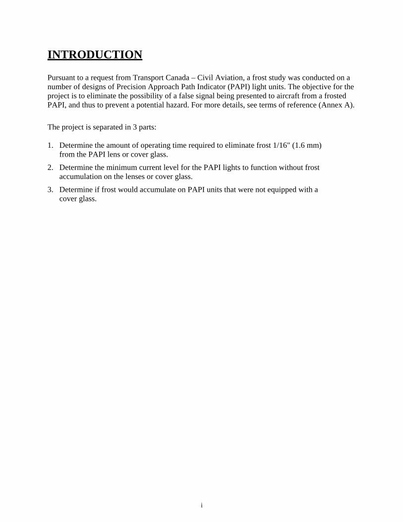
INTRODUCTION
Pursuant to a request from Transport Canada – Civil Aviation, a frost study was conducted on a number of designs of Precision Approach Path Indicator (PAPI) light units. The objective for the project is to eliminate the possibility of a false signal being presented to aircraft from a frosted PAPI, and thus to prevent a potential hazard. For more details, see terms of reference (Annex A).
The project is separated in 3 parts: 1. Determine the amount of operating time required to eliminate frost 1/16" (1.6 mm)
from the PAPI lens or cover glass.
2. Determine the minimum current level for the PAPI lights to function without frost accumulation on the lenses or cover glass.
3. Determine if frost would accumulate on PAPI units that were not equipped with a cover glass.

Intentionally left blank

APPENDIX “A”
TERMS OF REFERENCE Study of PAPI Frost/Dew Cover (Phase 1)
Transport Canada – Civil Aviation Aerodrome Safety Technical Evaluation Engineering (AARME) Aerodrome Electrical Systems

Intentionally left blank
Study of PAPI Frost Tests Appendix A
A-1
1.0 OBJECTIVE The study of frost/dew cover on the front of Precision Approach Path Indicator (PAPI) light units is seginented into number of phases, each evolving from the other as more knowledge and data is obtained. The ultimate objective of the overall project is to attain a new equipment specification requirement and associated test procedure for This contract covers Phase 1 which is in two Parts:
Part 1 For purpose of determining a maximum time allowable to anticipate the elimination of frost/dew cover from PAPI, three manufacturers' products are tested. The products are of ADB/Siemens, Cegelec, and Crouse-Hinds. The ADB/Siemens' product is provided in two formats; with and without a front cover glass. Effectively, therefore, the number of products to be tested is five.
Part 2 For purpose of determining the minimum current at which PAPI products may be operated continuously and thus prevent the accumulation frost/dew cover in the first place.
Phase 2 (not part of this contract) involves the further investigation of variables applicable to the ADB/Siemens' product. These variables relate to the type of front cover glass or lack of, such as;
1. No cover glass so that frost/dew cover will be on the exposed lens.
2. With regular cover glass
3. With special cover glass which has a characteristic of preventing the adhesion of water droplets. This special glass is termed the "anti-fog" glass.
4. With special cover glass with vertical striations intended to capture radiant energy. This special glass is termed the "wired" glass.
Phase 2 will cover the same Parts as Phase 1, with the objective of determining if use of the anti-fog or wired cover glasses will lead to an improvement of performance.
2.0 BACKGROUND The occurrence of frost on the front cover glass of ADB/Siemens' PAPI light unit was first reported by the Quebec Region of Transport Canada. The presence of frost on the front of the PAPI unit caused the signal which normally has a split color display of red/white (the white as the top portion and the red as the bottom portion) to be diffused so that there is a mixture of colors and the unit, as seen by a pilot at distance appears to be only white in color. Since white is intended as a "flyup" signal, the frost cover gives false instruction to the pilot.

Study of PAPI Frost Tests Appendix A
A-2
At this time, to overcome the problem of false signals, Transport Canada has directed airports to; (1) at Air Traffic Services (ATS) controlled sites to operate the PAPI at least a half hour at maximum brightness or 6.6 amperes prior to its use by aircraft, and (2) at Aircraft Radio Control of Airport Lighting (ARCAL) provisioned sites to have the PAPI operated continuously at 4.8 amperes. The former strategy is to allow sufficient time for the frost to melt or dew to evaporate. The latter strategy is to prevent the accumulation of frost/dew cover in the first place, as ARCAL permits pilot operation of the lighting and prior energization is not possible. In both cases the purpose is to ensure a true signal before its observation and use by aircraft.
The above criteria is based upon a conservative evaluation of site experience and previous testing. Since their application creates an economical and operational burden, it is desired to do testing by this contract so as to see if the criteria can be refined. That is to lessen the time of prior energization and to reduce the current level for continuous operation (this reducing the power consumption).
The PAPI light units are supplied by constant current regulators of either 5 or 3 steps according to the following tables.
TABLE 1: OUTPUT CURRENT VERSUS INTENSITY STEPS – 5 STEP REGULATORS
Brightness Level Intensity (percent) Current (rms amperes) Allowable Range
5 100 6.6 6.40 – 6.70 4 25 5.2 5.04 – 5.36 3 5 4.1 3.98 – 4.22 2 1 3.4 3.30 – 3.50 1 0.2 2.8 2.72 – 2.88
TABLE 2: OUTPUT CURRENT VERSUS INTENSITY STEPS – 3 STEP REGULATORS
Step Nominal Output (amperes rms) Intensity (percent) Allowable Range
3 6.6 100 6.40 – 6.70 2 5.5 30 5.33 – 5.67 1 4.8 10 4.66 – 4.94
For testing of continuous operation of PAPI, the possible currents are, therefore, 2.8, 3.4, 4.1, 4.8, 5.2, 5.5 and 6.6 amperes. Because of the closeness of 5.2 and 5.5 amperes the first can be used leading to a possible testing at six levels of 2.8, 3.4, 4.1, 4.8, 5.2, and 6.6 amperes. For testing without the use of regulators, the level is RMS current of a suitable power supply.
It is of importance during testing that each of the PAPI units have an equal thickness of frost. Thus the need for a precise method of frost thickness measurement.
Arrangements will be made by the Client for provision of the PAPI units to the Consultant.

Study of PAPI Frost Tests Appendix A
A-3
3.0 GENERAL 3.1 “Client” means the Department of Transportation represented by the Director,
Aerodrome Safety, Civil Aviation, Transport Canada, Place de Ville – Tower C, Ottawa, Ontario, K1A 0N8.
3.2 The project will be carried out under the direction of the Mr. A. Mazur, Chief, Technical Evaluation Engineering (613) 990-1424. The designated project manager for this project and will be Mr. Franco Mangano, Airside Electrical Systems Engineer (613) 990-1366 who will manage it on a day-to-day basis.
4.0 TECHNICAL REQUIREMENTS / SCOPE OF WORK 4.1 Arrange for a preliminary Consultant/Client meeting to discuss the scope of work.
4.2 Determine a method to measure the thickness of frost on the PAPI light units. Use the Canada Motor Vehicle Safety Standard, No. 103, "Windshield Defrosting and Defogging", 24 January 1995, for application of frost, except that the temperature shall be minus 20 degrees Celsius. Since this standard does not stipulate the thickness of applied frost, the standard shall first be used to determine thickness. This thickness be either that derived from the standard or 1/16 inch, whichever is greater.
4.3 Items of Part 1
Note: The ADB/Siemens product has two variations; with and without cover glass. Since only one PAPI product is available, it is left to the contractor to devise the means to test these variations along with the Cegelec and Crouse-Hinds products.
4.3.1 Soak the PAPI units in a cold chamber to a temperature of minus 20 degrees Celsius.
4.3.2 Provide visual isolation barriers to ensure that there is no signal interference between the units during the test.
4.3.3 Arrange the units so that their signal is projected onto a white non-spectral screen at a distance of at least 3 m.
4.3.4 Apply an equal layers (thickness) of frost on the front of each PAPI light unit.
4.3.5 Using video recording, determine the time to defrost after turning the units on at brightness level 5 at 6.6 amperes. The time shall be measured from the moment of lamp energization to the moment when the projected signal has returned to a distinctive red/white display.

Study of PAPI Frost Tests Appendix A
A-4
4.4 Items of Part 2
4.4.1 Place the light units in a cold chamber, at minus 20 degrees Celsius.
4.4.2 Place a thermocouple device at the middle of one of the lenses or of the cover glass to monitor the temperatures during the test.
4.4.3 Energize the light units at 2.8 amperes and allow the units to operate until they are thermally stabilized.
4.4.4 Attempt to apply frost to the front of each light unit, determining whether the warmth of the units are preventing frost accumulation.
4.4.5 If the unit is not maintained free of frost at 2.8 amperes, then repeat this test at each supply current level of 3.4, 4.1, 4.8, 5.2 and 6.6 amperes, stopping at the level at which frost free operation is reached.
4.4.6 Ensure that the thermal stability of the units is achieved between each current change.
4.4.7 The temperature of the lens/cover glass shall be monitored and recorded continuously throughout the testing.
4.5 Deliverable: Prepare a report of the work done and submit to the Client maximum two weeks after the completion of the test for review and comment. One week after reception of Client comments, finalize the report and submit as the deliverable of this project. Submit the final version of the report to the Client, both as a hard copy printout and an electronic file. The report shall fully detail the testing and make conclusion as to achievement of the objectives. The final draft report and final version shall be provided in the form of two printed copies and electronic files on computer diskette.
4.6 The text of the report shall be prepared using a word processing programs whose files are retrievable with Microsoft Word, version 7.0. Any diagrams shall be prepared in a format retrievable by CorelDraw, version 7.0.
5.0 CODES, STANDARDS, AND REFERENCES 5.1 Work in accordance with Department of Transport's policies, standards and
guidelines. For visual aids standards, the Contractor will be informed by the Client as to the source of reference.
6.0 SPECIAL REQUIREMENTS 6.1 Intellectual Property. All ownership and intellectual property rights for the deliverables
(i.e. the technical circular) of this contract shall reside with Transport Canada.
7.0 COMMENCEMENT AND COMPLETION DATES 7.1 The work of this project will commence immediately upon award of contract.
7.2 The project is to be completed not later than 30 December 1997.

Study of PAPI Frost Tests Appendix A
A-5
8.0 MODIFICATION, ADDITION TO, OR REDUCTION OF WORK 8.1 If modification, additional to or reduction of the scope of work is required the
Client shall notify the Contractor in writing.
9.0 FEES AND DISBURSEMENTS 9.1 The fee for Professional Services, Associated Costs (long distance calls, telex,
fax, courier, reproduction costs, etc.) shall be an all-inclusive fixed lump sum.
9.2 No fee payment will be made by the Department of Transport to remedy errors or omissions for which the Contractor is responsible, and which the Contractor shall remedy and correct as appropriate.
9.3 Invoices, supported by time sheets, receipts, and vouchers, shall be submitted in duplicate and itemized to permit proper audit.
9.4 Invoices, shall be submitted at the 50 percent and 100 percent completion milestones, upon acceptance of work completed by the Client.

Intentionally left blank

APPENDIX A
DEFROSTING TEST AND MINIMUM CURRENT TEST PHOTOGRAPHS

Intentionally left blank

A-9
TEST PROCEDURE
LABORATORY BOOK FOR PRECISION APPROACH PATH INDICATOR (PAPI)
Name of PAPI: Date:
Test type: Time:
Test Amp.:
Test number: By (initials) :
BEFORE THE TEST: 1. We ensured that the test equipment conformed to standards (Check for ISO stamp).
2. We obtained the materials required to conduct the test procedures as stipulated in Canada Motor Vehicle Safety Standard, (CMVSS) 103. (paint gun, pressure regulator, Hydra, timer Cra-Lab, video camera, digital camera).
3 We installed a white 8' x 8' panel to receive the projected signal from the PAPI'S.
4 We installed the PAPI units on a table at the other end of the chamber (the PAPI projected the signal onto the panel surface). The supply current for the PAPI light unit was set at 6.6 Amp.
5. We adjusted the distance of the table so that the emitted light beam just covered the width of the target panel.
6. We lowered the temperature of the cold chamber to -20 degrees Celcius and confirmed this using a thermocouple measuring device.
7. A sign identifying the test being performed was prepared.

A-10
DEFROSTING: Note: For this test, it was necessary to measure the thickness of the applied frost when sprayed
with water. The adopted technique was to install a measured metallic disc between the two PAPI lenses, to create frost by spraying water vapor from a paint gun equally onto the entire front surface of the PAPI unit under test, including the metallic disc. After completing the application of water, the disc was removed and the total thickness of the disc plus frost was measured using a dial caliper. The thickness of the frost was measured as the difference between the total thickness and the thickness of the metallic disc.
1. A pre-test photograph was taken of the equipment under test.
2. A means to measure the thickness of the frost applied on the PAPI surface was installed (metallic disc between the lenses).
3. Vaporized water was sprayed onto the front of the PAPI unit (entire surface of optical window) to form a 1/16" thickness of frost (0.175 ml/cm2)
4. The application of vaporized water was video-taped and a still picture was taken after the application.
5. The metal measuring disc was removed and the total thickness of the disc plus the frost deposit was measured.
6. The thickness of the frost was calculated.
7. A 30 minutes time period was allowed to elapse to allow, for temperature stabilization as specified in CMVSS 103.
8. The video camera was started, the PAPI was turned on and operated at 6.6 Amperes while simultaneously starting a timer.
9. The end of the test was acknowledged as the moment when the signal displayed on the screen was identical to the signal displayed when the PAPI light unit was operating without any frost cover.
10. The time required for the PAPI defrosting to the point of producing a signal the same as a PAPI without frost cover was noted.
11. A post-test still photograph was taken.

A-11
MINIMAL CURRENT TEST: 1. A thermocouple was attached to the centre of one of the two PAPI lenses or at the beam
centre point for PAPI equipped with a cover glass.
2. A pre-test still photograph was taken of the equipment under test and the test identification sign.
3. The PAPI light unit was operated at the specified current test level.
4. The test was delayed until there was a stabilization of the lens or cover glass temperature (approximately 1 hour).
5. The lens temperature was recorded.
6. An attempt was made to apply a thin coat of vaporized water onto the lens surface or onto the portion of the cover glass without the thermocouple. This procedure was video-taped.
7. A verification was made to see if the frost melted immediately from the lens or cover glass
8. The test was considered successful if the frost melted and was eliminated. If this did not occur and permanent frost remained, the test was repeated by raising the current to the next required level.
9. A post-test still photograph was taken with the test identification sign.
FROSTING TEST 1. The temperature of the cold chamber was lowered to -40 degrees Celsius and was confimed
using a thermocouple measuring device.
2. The PAPI was installed in the chamber at -40 degrees Celsius.
3. One hour was allow to pass to ensure that the PAPI attained thermal stability at -40 degrees Celsius.
4. Another environmental chamber was prepared at a temperature of + 35 degrees Celsius with a dew point of 25 to 30 degrees Celsius.
5. The PAPI was taken from the -40 degrees Celsius chamber and placed in the +35 degrees Celsius chamber.
6. 30 seconds was allowed to pass before taking a still photograph to allow for the possibility of frost formation.
7. Reference still photographs of the exterior, the interior and the front view of the PAPI were taken.

TEST REPORT STUDY OF PAPI FROST/DEW
Test Period: November, 1997 Equiptment: Precision Approach Path Indicator (PAPI) Project No. 98-5113
A-12
TEST RESULTS
DEFROSTING TIME TEST (PART 1) Test # PAPI Manufacturer Cover glass
(Yes/No) Ice Thickness (inch)
RMS Current (Amp)
Defrosting time (min.)
1 Cegelec N/A 0.060 6.60 56 2 Siemens Yes/Antifog 0.055 6.60 25 3 Downing N/A 0.060 N/A120 V Not defrosting 4 Siemens Yes/Wired 0.060 6.60 3 13 Crouse-Hinds N/A 0.055 6.60 8 14 Siemens No 0.060 6.60 >30, no improvement
after 20 minutes * * (1/2") of frost (doughnut shape remains around the edge of the lens)
MINIMUM CURRENT TEST (PART 2) Test # PAPI Manufacturer Cover glass
(Yes/No) RMS Current (Amp)
Lens/glass Temperature (°C)
Accumulation of frost (Yes/No)
5 Cegelec N/A 2.8 -12.7 Glass temp too low 6 Siemens Yes/Antifog 2.8 -12.3 Glass temp too low 7 Siemens Yes/Antifog 3.4 -6.5 Yes 8 Cegelec N/A 3.4 -4.3 Yes 9 Cegelec N/A 4.1 3.7 Yes 10 Siemens Yes/Antifog 4.1 6.1 No 11 Cegelec N/A 4.8 17.7 No 12 Siemens Yes/Antifog 4.8 7.2 No 15 Crouse-Hinds N/A 4.1 8.1 Yes 16 Siemens No 4.1 -2.5 Yes 17 Crouse-Hinds N/A 4.8 23.5 No 18 Siemens No 4.8 9.3 Yes 19 Siemens No 5.2 17.0 Yes (slowly defrosting) 20 Siemens No 5.5 23.6 Yes (slowly defrosting)

TEST REPORT STUDY OF PAPI FROST/DEW
Test Period: November, 1997 Equiptment: Precision Approach Path Indicator (PAPI) Project No. 98-5113
A-13
FROSTING TEST (PART 3) Test # PAPIManufacturer Frost on lens (Yes/No) Frost on cover glass
1 Sample glass N/A Yes, both sides 2 Crouse-Hinds Yes N/A 3 Cegelec Yes, less than Crouse-Hinds* N/A 4 Siemens N/A Yes
*Because of the internal baffles used in the construction of the Cegelec PAPI unit, air circulated in front of the unit keeping the moist air out, (see drawing below). A longer time was required for frost to accumulate on the lens of the Cegelec PAPI as compared to the PAPI manufactured by Crouse-Hinds.
FIGURE 1:
RETROFLECTIVE HELIPORT MARKER Test # Retroflective marker
manufacturer Light source Luminance without
frost Cd/m2 Luminance with light frost cover ice Cd/m2
1 REGINALD BENNETT INC. Downing 420 120

A-14
CONCLUSIONS
DEFROSTING TEST: The best performances were obtained with the ADB/Siemens fixture equipped with the modified (heat absorbing black striping) cover glass, defrosting was completed in 3 minutes.
MINIMUM CURRENT TEST: For the ADB/Siemens unit equipped with anti-fog cover glass, the minimum current required for frost free operation was 4.1 amp. The required minimum current for frost-free operation for the Cegelec and the Crouse Hinds PAPI's was 4.8 amp.
The cover glass/lens temperature was monitored using a thermocouple bonded to the cover glass or lens with a black butyl adhesive material. The purpose of the use of a thermocouple was to determine when the lens reached thermal stability and was not meant to measure an absolute value of the temperature.
FROSTING TEST: All units accumulated frost on their lenses or cover glass. The lens of Crouse-Hinds PAPI frosted in advance of the lens of Cegelec.
RECOMMENDATIONS:
We recommend that other tests in the field be made to confirm the above conclusions which would also consider other parameters, such as the cooling effect of the wind, the effect of the sun on the observation of the output signal from distances greater than the 12 foot laboratory distance, the "real world" frost deposit thickness and deposit rate of, as well as other meterological conditions. We also need to establish a scientific way of calculating the degradation of the PAPI to what would be considered as a false signal, from a true signal.

ANNEX A
TERMS OF REFERENCE

Intentionally left blank

TEST REPORT STUDY OF PAPI FROST/DEW
Test Period: November, 1997 Equiptment: Precision Approach Path Indicator (PAPI) Project No. 98-5113
A-17
1. ADB/Siemens Papi.
2. Inside view of ADB/Siemens.

TEST REPORT STUDY OF PAPI FROST/DEW
Test Period: November, 1997 Equiptment: Precision Approach Path Indicator (PAPI) Project No. 98-5113
A-18
3. Cegelec Papi.
4. Inside Cegelec.

TEST REPORT STUDY OF PAPI FROST/DEW
Test Period: November, 1997 Equiptment: Precision Approach Path Indicator (PAPI) Project No. 98-5113
A-19
5. Crouse-Hinds.
6. Inside Crouse-Hinds.

TEST REPORT STUDY OF PAPI FROST/DEW
Test Period: November, 1997 Equiptment: Precision Approach Path Indicator (PAPI) Project No. 98-5113
A-20
7. General view of the test set-up.
8. Papi installation

TEST REPORT STUDY OF PAPI FROST/DEW
Test Period: November, 1997 Equiptment: Precision Approach Path Indicator (PAPI) Project No. 98-5113
A-21
9. Test #1, pre-test.
10. Test #1, post-test.

TEST REPORT STUDY OF PAPI FROST/DEW
Test Period: November, 1997 Equiptment: Precision Approach Path Indicator (PAPI) Project No. 98-5113
A-22
11. Test #2, pre-test.
12. Test #2, post-test.

TEST REPORT STUDY OF PAPI FROST/DEW
Test Period: November, 1997 Equiptment: Precision Approach Path Indicator (PAPI) Project No. 98-5113
A-23
13. Test #3, pre-test. IDEM AS PRE-TEST 14. Test #3, post-test.

TEST REPORT STUDY OF PAPI FROST/DEW
Test Period: November, 1997 Equiptment: Precision Approach Path Indicator (PAPI) Project No. 98-5113
A-24
15. Test #4, pre-test.
16. Test #4, post-test.

TEST REPORT STUDY OF PAPI FROST/DEW
Test Period: November, 1997 Equiptment: Precision Approach Path Indicator (PAPI) Project No. 98-5113
A-25
17. Test #7, pre-test.
18. Test #7, post-test.

TEST REPORT STUDY OF PAPI FROST/DEW
Test Period: November, 1997 Equiptment: Precision Approach Path Indicator (PAPI) Project No. 98-5113
A-26
19. Test #8, pre-test.
20. Test #9, pre-test.

TEST REPORT STUDY OF PAPI FROST/DEW
Test Period: November, 1997 Equiptment: SIEMENS, CROUSE-HINDS & CEGELEC Project No. 98-5113
A-27
21. Test #9, post-test.
22. Test #10, pre-test.

TEST REPORT STUDY OF PAPI FROST/DEW
Test Period: November, 1997 Equiptment: SIEMENS, CROUSE-HINDS & CEGELEC Project No. 98-5113
A-28
23. Test #10, post-test.
24. Test #11, pre-test.

TEST REPORT STUDY OF PAPI FROST/DEW
Test Period: November, 1997 Equiptment: SIEMENS, CROUSE-HINDS & CEGELEC Project No. 98-5113
A-29
25. Test #11, post-test.
26. Test #12, pre-test.

TEST REPORT STUDY OF PAPI FROST/DEW
Test Period: November, 1997 Equiptment: SIEMENS, CROUSE-HINDS & CEGELEC Project No. 98-5113
A-30
27. Test #12, post-test.
28. Test #13, pre-test.

TEST REPORT STUDY OF PAPI FROST/DEW
Test Period: November, 1997 Equiptment: SIEMENS, CROUSE-HINDS & CEGELEC Project No. 98-5113
A-31
29. Test #13, post-test.
30. Test #14, pre-test.

TEST REPORT STUDY OF PAPI FROST/DEW
Test Period: November, 1997 Equiptment: SIEMENS, CROUSE-HINDS & CEGELEC Project No. 98-5113
A-32
31. Test #14, post-test.
32. Test #15, pre-test.

TEST REPORT STUDY OF PAPI FROST/DEW
Test Period: November, 1997 Equiptment: SIEMENS, CROUSE-HINDS & CEGELEC Project No. 98-5113
A-33
33. Test #15, post-test.
34. Test #16, pre-test.

TEST REPORT STUDY OF PAPI FROST/DEW
Test Period: November, 1997 Equiptment: SIEMENS, CROUSE-HINDS & CEGELEC Project No. 98-5113
A-34
35. Test #16, post-test.
36. Test #17, pre-test.

TEST REPORT STUDY OF PAPI FROST/DEW
Test Period: November, 1997 Equiptment: SIEMENS, CROUSE-HINDS & CEGELEC Project No. 98-5113
A-35
37. Test #18, pre-test.
38. Test #19, post-test.

TEST REPORT STUDY OF PAPI FROST/DEW
Test Period: November, 1997 Equiptment: SIEMENS, CROUSE-HINDS & CEGELEC Project No. 98-5113
A-36
39. Test #19, post-test.
40. Test #20, post-test.

APPENDIX B
FROSTING TEST PHOTOGRAPHS
Intentionally left blank

TEST REPORT STUDY OF PAPI FROST/DEW
Test Period: November, 1997 Equiptment: SIEMENS, CROUSE-HINDS & CEGELEC Project No. 98-5113
B-1
1. Sample glass frosting test #1.
2. Frosting test #2.

TEST REPORT STUDY OF PAPI FROST/DEW
Test Period: November, 1997 Equiptment: SIEMENS, CROUSE-HINDS & CEGELEC Project No. 98-5113
B-2
3. Frosting test #2.
4. Frosting test #3.

TEST REPORT STUDY OF PAPI FROST/DEW
Test Period: November, 1997 Equiptment: SIEMENS, CROUSE-HINDS & CEGELEC Project No. 98-5113
B-3
5. Frosting test #3.
6. Frosting test #3.

TEST REPORT STUDY OF PAPI FROST/DEW
Test Period: November, 1997 Equiptment: SIEMENS, CROUSE-HINDS & CEGELEC Project No. 98-5113
B-4
7. Frosting test #4.
8. Frosting test #4.

APPENDIX C
DEW TEST PHOTOGRAPH

Intentionally left blank

TEST REPORT STUDY OF PAPI FROST/DEW
Test Period: November, 1997 Equiptment: SIEMENS, CROUSE-HINDS & CEGELEC Project No. 98-5113
C-1
1. Before dew test #1.
2. After dew test #1.

TEST REPORT STUDY OF PAPI FROST/DEW
Test Period: November, 1997 Equiptment: SIEMENS, CROUSE-HINDS & CEGELEC Project No. 98-5113
C-2
3. Before dew test #2.
4. After dew test #2.

TEST REPORT STUDY OF PAPI FROST/DEW
Test Period: November, 1997 Equiptment: SIEMENS, CROUSE-HINDS & CEGELEC Project No. 98-5113
C-3
5. Before dew test #3.
6. After dew test #3.