Technical Drawing Ch 01.ppt
21
C H A P T E R O N E THE WORLDWIDE THE WORLDWIDE GRAPHIC LANGUAGE GRAPHIC LANGUAGE FOR DESIGN FOR DESIGN
-
Upload
mohd-nizam-shakimon -
Category
Documents
-
view
35 -
download
1
Transcript of Technical Drawing Ch 01.ppt

C H A P T E R O N E
THE WORLDWIDETHE WORLDWIDEGRAPHIC LANGUAGEGRAPHIC LANGUAGE
FOR DESIGNFOR DESIGN

Technical Drawing with Engineering Graphics, 14/eGiesecke, Hill, Spencer, Dygdon, Novak, Lockhart, Goodman
© 2012, 2009, 2003, Pearson Higher Education,Upper Saddle River, NJ 07458. • All Rights Reserved.2
OBJECTIVESOBJECTIVES
1. Describe the role of drawings in the design process.
2. Contrast concurrent versus traditional design processes.
3. List five professions that use technical drawings.
4. Describe four creativity techniques.
5. Explain why standards are important.
6. Identify uses of the graphic language.

Technical Drawing with Engineering Graphics, 14/eGiesecke, Hill, Spencer, Dygdon, Novak, Lockhart, Goodman
© 2012, 2009, 2003, Pearson Higher Education,Upper Saddle River, NJ 07458. • All Rights Reserved.3
UNDERSTANDING THEUNDERSTANDING THEROLE OF TECHNICAL DRAWINGSROLE OF TECHNICAL DRAWINGS
Technical drawings serve one of three purposes:
• Visualization
• Communication
• Documentation
(Courtesy of Woods Power-Grip Co., Inc.)
(Courtesy of Dynojet Research, Inc.)
(Courtesy of Seymourpowell.)

Technical Drawing with Engineering Graphics, 14/eGiesecke, Hill, Spencer, Dygdon, Novak, Lockhart, Goodman
© 2012, 2009, 2003, Pearson Higher Education,Upper Saddle River, NJ 07458. • All Rights Reserved.4
Concept SketchesConcept Sketches
Exploring many design options through quick sketches
(Courtesy of Lunar Design.)
(Courtesy of Seymourpowell.)

Technical Drawing with Engineering Graphics, 14/eGiesecke, Hill, Spencer, Dygdon, Novak, Lockhart, Goodman
© 2012, 2009, 2003, Pearson Higher Education,Upper Saddle River, NJ 07458. • All Rights Reserved.5
The Stages of the Design ProcessThe Stages of the Design Process
1. Problem identification: Problem identification: First, a clear statement of the need for and objectives for the design must be written.
2. Ideation: Ideation: Technical sketches are often used to convey concepts to multidisciplinary teams.
3. Refinement/analysis: Refinement/analysis: Designs may be rethought, based on engineering analysis. CAD models and sketches are useful during the analysis and compromise stage. Accurate 2D or 3D CAD models and drawings are created to refine the design.
4. Implementation/documentation:Implementation/documentation: Production and/or working drawings providing the details of manufacture and assembly are finalized and approved.

Technical Drawing with Engineering Graphics, 14/eGiesecke, Hill, Spencer, Dygdon, Novak, Lockhart, Goodman
© 2012, 2009, 2003, Pearson Higher Education,Upper Saddle River, NJ 07458. • All Rights Reserved.6
Concurrent EngineeringConcurrent EngineeringTraditionally, design and manufacturing activities have taken place in sequential order rather than concurrently (simultaneously). This step-by-step approach seems logical, but in practice it has been found to be wasteful.
Concurrent engineering is a systematic approach that integrates the design and manufacture of products with the goal of optimizing all elements involved in the life cycle of the product.
The Concurrent Process

Technical Drawing with Engineering Graphics, 14/eGiesecke, Hill, Spencer, Dygdon, Novak, Lockhart, Goodman
© 2012, 2009, 2003, Pearson Higher Education,Upper Saddle River, NJ 07458. • All Rights Reserved.7
Life cycle designLife cycle design
Life cycle design means that all aspects of a product (such as design, development, production, distribution, use, and its ultimate disposal and recycling) are considered simultaneously.
The basic goals of concurrent engineering are to minimize product design and engineering changes and to reduce the time and cost involved in taking a product from design concept through production and ultimately to introduction into the marketplace.
Technical Drawing with Engineering Graphics, 14/eGiesecke, Hill, Spencer, Dygdon, Novak, Lockhart, Goodman
© 2012, 2009, 2003, Pearson Higher Education,Upper Saddle River, NJ 07458. • All Rights Reserved.8
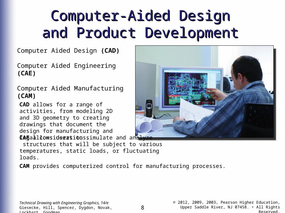
Computer-Aided DesignComputer-Aided Designand Product Developmentand Product Development
Computer Aided Design (CAD) Computer Aided Engineering (CAE)
Computer Aided Manufacturing (CAM)
CAE allows users to simulate and analyze structures that will be subject to various temperatures, static loads, or fluctuating loads.
CAM provides computerized control for manufacturing processes.
CAD allows for a range of activities, from modeling 2D and 3D geometry to creating drawings that document the design for manufacturing and legal considerations.

Technical Drawing with Engineering Graphics, 14/eGiesecke, Hill, Spencer, Dygdon, Novak, Lockhart, Goodman
© 2012, 2009, 2003, Pearson Higher Education,Upper Saddle River, NJ 07458. • All Rights Reserved.9
The Digital DatabaseThe Digital Database
(Courtesy of Parametric Technology Corporation)
All the information to manage, design, analyze, simulate, package, market, and manufacture a product can be shared with a diverse group of users through a single complex digital database.

Technical Drawing with Engineering Graphics, 14/eGiesecke, Hill, Spencer, Dygdon, Novak, Lockhart, Goodman
© 2012, 2009, 2003, Pearson Higher Education,Upper Saddle River, NJ 07458. • All Rights Reserved.10
Designing Quality into ProductsDesigning Quality into Products
DFSS Design for Six Sigma is an approach that uses engineering and statistical tools to design products in a way that predicts and minimizes customer and manufacturing problems.
Six Sigma is a process originated at Motorola to improve quality by reducing or eliminating defects.
DMAIC Define, Measure, Analyze, Improve, and Control are steps defined in a continuous improvement process that attempts to define and ensure critical to function (CTF) characteristics.
QFD Quality Function Deployment is a tool for decision making that helps companies focus on a customer-driven approach and set of product characteristics.

Technical Drawing with Engineering Graphics, 14/eGiesecke, Hill, Spencer, Dygdon, Novak, Lockhart, Goodman
© 2012, 2009, 2003, Pearson Higher Education,Upper Saddle River, NJ 07458. • All Rights Reserved.11
ENGINEERING DESIGN STAGE 1ENGINEERING DESIGN STAGE 1Identify the Customer and the Problem
The engineering design process begins with recognizing or identifying these needs and considering the economicfeasibility of fulfilling them.
A successful design must not only solve the problem but also meet the needs and wishes of the customer.
(Project developed and created by Philips Design.)

Technical Drawing with Engineering Graphics, 14/eGiesecke, Hill, Spencer, Dygdon, Novak, Lockhart, Goodman
© 2012, 2009, 2003, Pearson Higher Education,Upper Saddle River, NJ 07458. • All Rights Reserved.12
ENGINEERING DESIGN STAGE 2ENGINEERING DESIGN STAGE 2Generate Concepts
(Courtesy of Seymourpowell.)
During this stage, often called the ideation stage, many ideas—reasonable and otherwise—are collected.
The ability to freely create technical sketches lets you present and share ideas and record them so you can refer to solutions, inspirations, and breakthroughs that come to light during this creative stage of the process.

Technical Drawing with Engineering Graphics, 14/eGiesecke, Hill, Spencer, Dygdon, Novak, Lockhart, Goodman
© 2012, 2009, 2003, Pearson Higher Education,Upper Saddle River, NJ 07458. • All Rights Reserved.13
ENGINEERING DESIGN STAGE 3ENGINEERING DESIGN STAGE 3Compromise Solutions
The design teamselects various features of the concepts generated in theideation stage and combines them into one or more promisingcompromise solutions.
Many of these problems are solved graphically, using schematic drawings in which various parts are shown in skeleton form. For example, pulleys and gears are represented by circles, an arm by a single line, and a path of motion by centerlines
2D CAD Drawing. (Courtesy of Seymourpowell.)

Technical Drawing with Engineering Graphics, 14/eGiesecke, Hill, Spencer, Dygdon, Novak, Lockhart, Goodman
© 2012, 2009, 2003, Pearson Higher Education,Upper Saddle River, NJ 07458. • All Rights Reserved.14
ENGINEERING DESIGN STAGE 4ENGINEERING DESIGN STAGE 4Models and Prototypes
3D CAD Model. This 3D CAD model of a design for the Mars rover was constructed to act as a virtual prototype for the design. (Courtesy of Byron Johns.)
Design teams often construct a model to scale to study, analyze,and refine a design.
3D CAD Model of the SAAR Brake. (Courtesyof Dynojet Research, Inc.)

Technical Drawing with Engineering Graphics, 14/eGiesecke, Hill, Spencer, Dygdon, Novak, Lockhart, Goodman
© 2012, 2009, 2003, Pearson Higher Education,Upper Saddle River, NJ 07458. • All Rights Reserved.15
Rapid PrototypingRapid PrototypingRapid prototyping systems allow designers to generate parts quickly, directly from 3D models, for mockup and testing.
Rapid Prototyping. The ZPrinter 450 from Zcorp “printed” the colored part shown in about four hours. (Courtesy of Z Corporation.)

Technical Drawing with Engineering Graphics, 14/eGiesecke, Hill, Spencer, Dygdon, Novak, Lockhart, Goodman
© 2012, 2009, 2003, Pearson Higher Education,Upper Saddle River, NJ 07458. • All Rights Reserved.16
ENGINEERING DESIGN STAGE 5ENGINEERING DESIGN STAGE 5Production or Working Drawings
The drawings, showing the necessary views, include the material, dimensions, required tolerances, notes, and other information needed to describe each part sufficiently for it to be manufactured consistently. These drawings of the individual parts are also known as detail drawings.
Detail Drawing for the SAAR Brake Air Can Mounting Bracket.(Courtesy of Dynojet Research, Inc.)

Technical Drawing with Engineering Graphics, 14/eGiesecke, Hill, Spencer, Dygdon, Novak, Lockhart, Goodman
© 2012, 2009, 2003, Pearson Higher Education,Upper Saddle River, NJ 07458. • All Rights Reserved.17
Assembly DrawingsAssembly DrawingsAn assembly drawing, shows how all the parts go together in the complete product.
Assembly Drawing for the SAAR Brake. (Courtesy of Dynojet Research, Inc.)

Technical Drawing with Engineering Graphics, 14/eGiesecke, Hill, Spencer, Dygdon, Novak, Lockhart, Goodman
© 2012, 2009, 2003, Pearson Higher Education,Upper Saddle River, NJ 07458. • All Rights Reserved.18
DRAFTING STANDARDSDRAFTING STANDARDSThere are standards that support a uniform, effective graphic language for use in industry, manufacturing, engineering, and science.
In the United States, providing these standards has been the work of the American National Standards Institute (ANSI) with the American Society for Engineering Education (ASEE), the Society of Automotive Engineers (SAE), and the American Society of Mechanical Engineers (ASME).
International standards, often defined by the International Organization for Standardization (IOS), and the ASME or ANSI standards for drawing practices are similar in many respects.

Technical Drawing with Engineering Graphics, 14/eGiesecke, Hill, Spencer, Dygdon, Novak, Lockhart, Goodman
© 2012, 2009, 2003, Pearson Higher Education,Upper Saddle River, NJ 07458. • All Rights Reserved.19
CREATIVITY TECHNIQUESCREATIVITY TECHNIQUES
Examine Manufactured Products
Study the Natural World
Watch the Web
Research Patent Drawings
Design Groups
How do you develop new ideas?
The following websites are useful for engineering design:
• http://www.yahoo.com/headlines/ Yahoo’s site for the latest technology news and a one-week archive
• http://www.techweb.com/TechWeb site from CMP media
• http://www.uspto.gov/ U.S. Patent Office on-line search site

Technical Drawing with Engineering Graphics, 14/eGiesecke, Hill, Spencer, Dygdon, Novak, Lockhart, Goodman
© 2012, 2009, 2003, Pearson Higher Education,Upper Saddle River, NJ 07458. • All Rights Reserved.20
PRODUCT DEFINITIONPRODUCT DEFINITIONProduct definition refers to the collection of digital or hard copy documents that specify the physical and functional requirements for a product.

Technical Drawing with Engineering Graphics, 14/eGiesecke, Hill, Spencer, Dygdon, Novak, Lockhart, Goodman
© 2012, 2009, 2003, Pearson Higher Education,Upper Saddle River, NJ 07458. • All Rights Reserved.21
SHOWING THE DESIGN PROCESS IN ASHOWING THE DESIGN PROCESS IN A PORTFOLIOPORTFOLIO
A portfolio is a representative sample of work that helps communicate your skills and talents, usually to a prospective employer or client.
(Courtesy of John Mountz.)