Technical Datasheet PowerValue 11/31 T 10-20 kVA · PDF fileFrequency conversion Operating as...
13
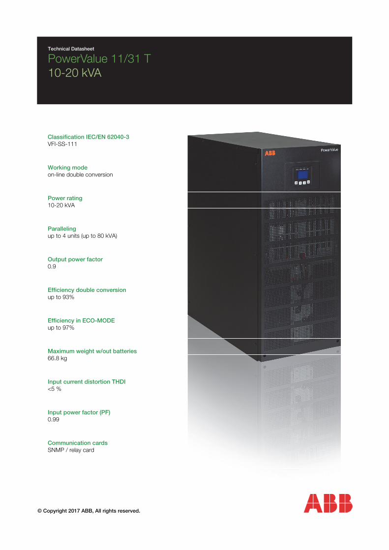
© Copyright 2017 ABB, All rights reserved. Technical Datasheet PowerValue 11/31 T 10-20 kVA Classification IEC/EN 62040-3 VFI-SS-111 Working mode on-line double conversion Power rating 10-20 kVA Paralleling up to 4 units (up to 80 kVA) Output power factor 0.9 Efficiency double conversion up to 93% Efficiency in ECO-MODE up to 97% Maximum weight w/out batteries 66.8 kg Input current distortion THDI <5 % Input power factor (PF) 0.99 Communication cards SNMP / relay card
Transcript of Technical Datasheet PowerValue 11/31 T 10-20 kVA · PDF fileFrequency conversion Operating as...
© Copyright 2017 ABB, All rights reserved.
Technical Datasheet
PowerValue 11/31 T 10-20 kVA
Classification IEC/EN 62040-3 VFI-SS-111 Working mode on-line double conversion Power rating 10-20 kVA Paralleling up to 4 units (up to 80 kVA) Output power factor 0.9 Efficiency double conversion up to 93% Efficiency in ECO-MODE up to 97% Maximum weight w/out batteries 66.8 kg Input current distortion THDI <5 % Input power factor (PF) 0.99 Communication cards SNMP / relay card
Table of contents
UPS Features ............................................................................................................ 3
Frequency conversion ........................................................................................................................... 3
Increasing the runtime ........................................................................................................................... 3
Automatic load start-up ........................................................................................................................ 3
Emergency power off (EPO) .................................................................................................................. 3
Wide input voltage and frequency range ............................................................................................... 3
Paralleling ............................................................................................................................................. 3
Batteries .................................................................................................................... 4
Battery autonomy ................................................................................................................................. 4
UPS devices .............................................................................................................. 5
10 & 20 kVA - Front view ................................................................................................................... 5
10 kVA - Rear view ............................................................................................................................. 5
20 kVA - Rear view ............................................................................................................................. 5
Options ...................................................................................................................... 6
Network interface card .......................................................................................................................... 6
Sensors ................................................................................................................................................ 6
Relay interface card .............................................................................................................................. 6
Technical specifications ........................................................................................... 7
General data ......................................................................................................................................... 7
Input characteristics .............................................................................................................................. 7
Output characteristics ........................................................................................................................... 8
Battery characteristics........................................................................................................................... 9
User interface ...................................................................................................................................... 10
Display & mimic diagram ..................................................................................................................... 10
Clearances .......................................................................................................................................... 11
Cables & fuses .................................................................................................................................... 12
Ratings ............................................................................................................................................... 12
PowerValue 11/31 T Technical Specifications
Page 2
Frequency conversion
Operating as a frequency converter,
PowerValue 11/31 T not only con-
verts the power supply frequency (50
Hz to/from 60Hz), but it also protects
the load from power disturbances
and guarantees additional battery
power in case of mains failure.
The operation and installation is sim-
ple and implies in correctly wiring the
UPS and in selecting the frequency
conversion mode in the LCD display.
Input frequency range: 40 - 70Hz
Output frequency: 50 or 60 Hz
Output de-rating: 1-phase input: 60% 3-phase input: no de-rating
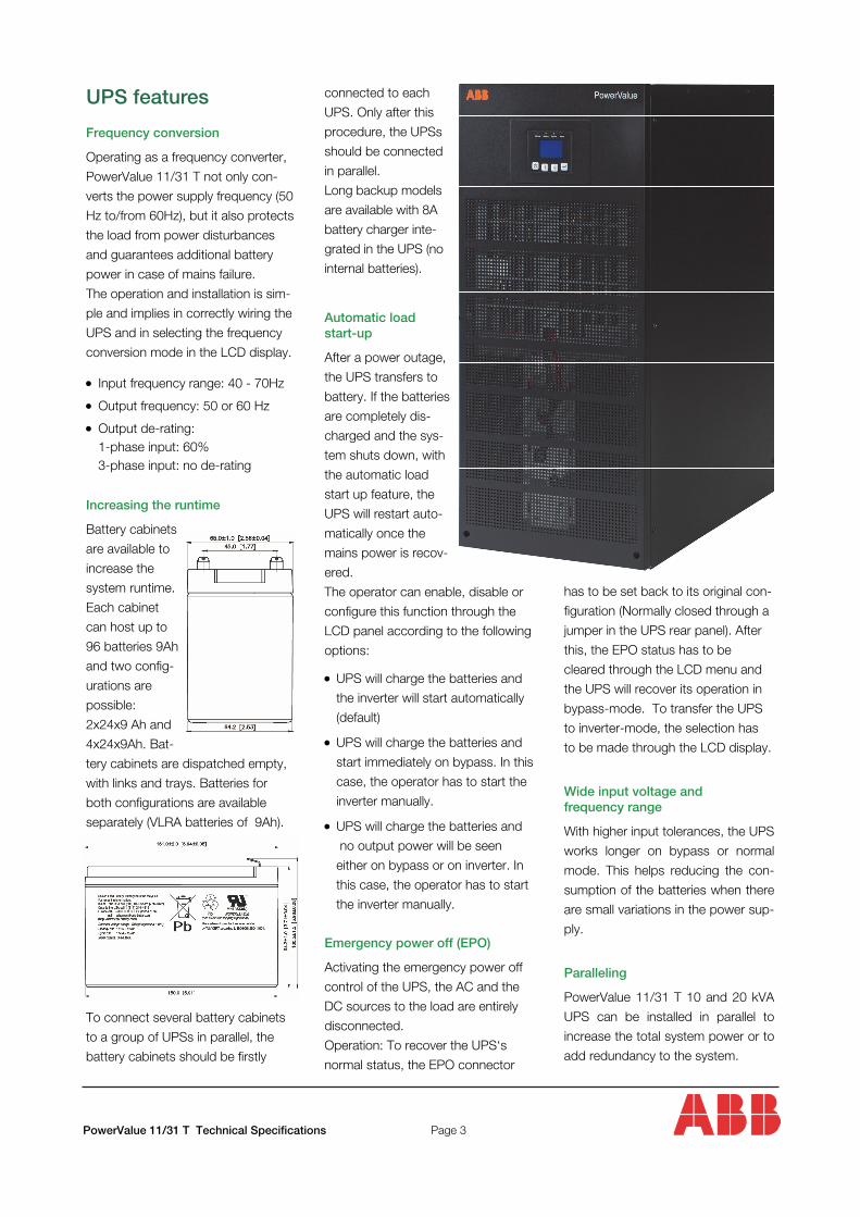
Increasing the runtime
Battery cabinets
are available to
increase the
system runtime.
Each cabinet
can host up to
96 batteries 9Ah
and two config-
urations are
possible:
2x24x9 Ah and
4x24x9Ah. Bat-
tery cabinets are dispatched empty,
with links and trays. Batteries for
both configurations are available
separately (VLRA batteries of 9Ah).
To connect several battery cabinets
to a group of UPSs in parallel, the
battery cabinets should be firstly
UPS features connected to each
UPS. Only after this
procedure, the UPSs
should be connected
in parallel.
Long backup models
are available with 8A
battery charger inte-
grated in the UPS (no
internal batteries).
Automatic load start-up
After a power outage,
the UPS transfers to
battery. If the batteries
are completely dis-
charged and the sys-
tem shuts down, with
the automatic load
start up feature, the
UPS will restart auto-
matically once the
mains power is recov-
ered.
The operator can enable, disable or
configure this function through the
LCD panel according to the following
options:
UPS will charge the batteries and
the inverter will start automatically
(default)
UPS will charge the batteries and
start immediately on bypass. In this
case, the operator has to start the
inverter manually.
UPS will charge the batteries and
no output power will be seen
either on bypass or on inverter. In
this case, the operator has to start
the inverter manually.
Emergency power off (EPO)
Activating the emergency power off
control of the UPS, the AC and the
DC sources to the load are entirely
disconnected.
Operation: To recover the UPS‘s
normal status, the EPO connector
has to be set back to its original con-
figuration (Normally closed through a
jumper in the UPS rear panel). After
this, the EPO status has to be
cleared through the LCD menu and
the UPS will recover its operation in
bypass-mode. To transfer the UPS
to inverter-mode, the selection has
to be made through the LCD display.
Wide input voltage and frequency range
With higher input tolerances, the UPS
works longer on bypass or normal
mode. This helps reducing the con-
sumption of the batteries when there
are small variations in the power sup-
ply.
Paralleling
PowerValue 11/31 T 10 and 20 kVA
UPS can be installed in parallel to
increase the total system power or to
add redundancy to the system.
PowerValue 11/31 T Technical Specifications
Page 3
Batteries
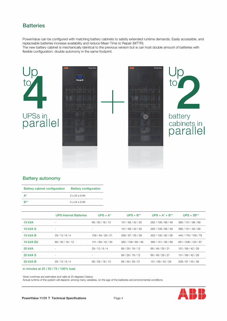
PowerValue can be configured with matching battery cabinets to satisfy extended runtime demands. Easily accessible, and replaceable batteries increase availability and reduce Mean Time to Repair (MTTR). The new battery cabinet is mechanically identical to the previous version but is can host double amount of batteries with flexible configuration: double autonomy in the same footprint.
Battery autonomy
UPS Internal Batteries UPS + A* UPS + B** UPS + A* + B** UPS + 2B**
10 kVA - 69 / 30 / 18 / 12 151 / 69 / 42 / 30 262 / 109 / 69 / 49 380 / 151 / 96 / 69
10 kVA S - - 151 / 69 / 42 / 30 262 / 109 / 69 / 49 380 / 151 / 93 / 69
10 kVA B 29 / 12 / 6 / 4 109 / 49 / 29 / 21 208 / 87 / 55 / 39 302 / 130 / 82 / 58 442 / 176 / 109 / 79
10 kVA B2 69 / 30 / 18 / 12 151 / 69 / 42 / 30 262 / 109 / 69 / 49 380 / 151 / 93 / 69 651 / 208 / 122 / 87
20 kVA - 29 / 12 / 6 / 4 69 / 29 / 18 / 12 69 / 49 / 29 / 21 151 / 69 / 42 / 29
20 kVA S - - 69 / 29 / 18 / 12 69 / 49 / 29 / 21 151 / 69 / 42 / 29
20 kVA B 29 / 12 / 6 / 4 69 / 29 / 18 / 12 69 / 49 / 29 / 21 151 / 69 / 42 / 29 208 / 97 / 55 / 39
in minutes at 25 / 50 / 75 / 100% load
PowerValue 11/31 T Technical Specifications Page 4
Given runtimes are estimates and valid at 20 degrees Celsius. Actual runtime of the system will depend, among many variables, on the age of the batteries and environmental conditions
Battery cabinet configuration Battery configuration
A* 2 x 24 x 9 Ah
B** 4 x 24 x 9 Ah
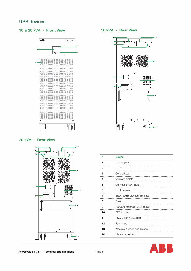
UPS devices
10 & 20 kVA - Front View
20 kVA - Rear View
10 kVA - Rear View
# Device
1 LCD display
2 LEDs
3 Control keys
4 Ventilation inlets
5 Connection terminals
6 Input breaker
7 Back feed protection terminals
8 Fans
9 Network interface / AS400 slot
10 EPO contact
11 RS232 port / USB port
12 Parallel port
13 Wheels / support and brakes
14 Maintenance switch
PowerValue 11/31 T Technical Specifications Page 5
Options
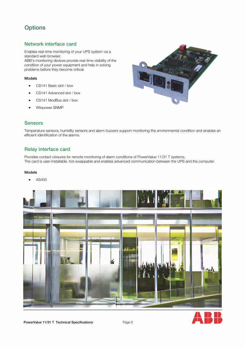
Network interface card
Enables real-time monitoring of your UPS system via a standard web browser. ABB’s monitoring devices provide real-time visibility of the condition of your power equipment and help in solving problems before they become critical.
Models
CS141 Basic slot / box
CS141 Advanced slot / box
CS141 ModBus slot / box
Winpower SNMP
Sensors
Temperature sensors, humidity sensors and alarm buzzers support monitoring the environmental condition and enables an efficient identification of the alarms.
Relay interface card
Provides contact closures for remote monitoring of alarm conditions of PowerValue 11/31 T systems. The card is user-installable, hot-swappable and enables advanced communication between the UPS and the computer.
Models
AS400
PowerValue 11/31 T Technical Specifications Page 6
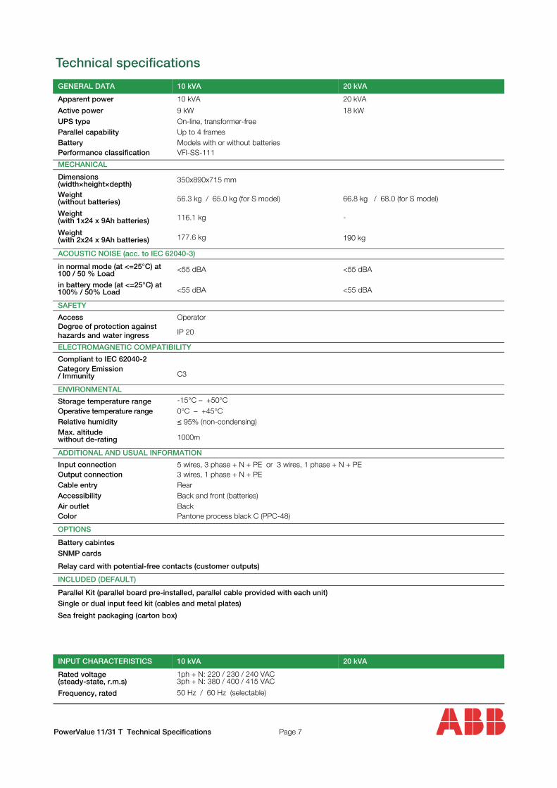
Technical specifications
GENERAL DATA 10 kVA 20 kVA
Apparent power 10 kVA 20 kVA
Active power 9 kW 18 kW UPS type On-line, transformer-freeParallel capability Up to 4 framesBattery Models with or without batteriesPerformance classification VFI-SS-111
MECHANICAL
Dimensions (width×height×depth) 350x890x715 mm
Weight (without batteries) 56.3 kg / 65.0 kg (for S model) 66.8 kg / 68.0 (for S model)
Weight (with 1x24 x 9Ah batteries) 116.1 kg -
Weight (with 2x24 x 9Ah batteries) 177.6 kg 190 kg
ACOUSTIC NOISE (acc. to IEC 62040-3)
in normal mode (at <=25°C) at 100 / 50 % Load <55 dBA <55 dBA
in battery mode (at <=25°C) at 100% / 50% Load <55 dBA <55 dBA
SAFETY
Access OperatorDegree of protection against hazards and water ingress IP 20
ELECTROMAGNETIC COMPATIBILITY
Compliant to IEC 62040-2Category Emission / Immunity C3
ENVIRONMENTAL
Storage temperature range -15°C – +50°COperative temperature range 0°C – +45°CRelative humidity ≤ 95% (non-condensing)Max. altitude without de-rating 1000m
ADDITIONAL AND USUAL INFORMATION
Input connection 5 wires, 3 phase + N + PE or 3 wires, 1 phase + N + PEOutput connection 3 wires, 1 phase + N + PECable entry RearAccessibility Back and front (batteries)Air outlet BackColor Pantone process black C (PPC-48)
OPTIONS
Battery cabintes SNMP cards
Relay card with potential-free contacts (customer outputs)
INCLUDED (DEFAULT)
Parallel Kit (parallel board pre-installed, parallel cable provided with each unit) Single or dual input feed kit (cables and metal plates)
Sea freight packaging (carton box)
INPUT CHARACTERISTICS 10 kVA 20 kVA
Rated voltage (steady-state, r.m.s)
1ph + N: 220 / 230 / 240 VAC 3ph + N: 380 / 400 / 415 VAC
Frequency, rated 50 Hz / 60 Hz (selectable)
PowerValue 11/31 T Technical Specifications Page 7
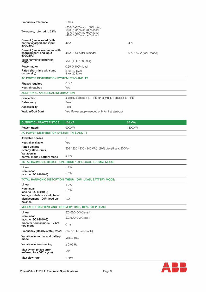
Frequency tolerance ± 10%
Tolerance, referred to 230V
-23% / +20% at <100% load,-33% / +20% at <80% load,-43% / +20% at <60% load,-48% / +20% at <40% load
Current (r.m.s), rated (with battery charged and input 400/230V)
42 A 84 A
Current (r.m.s), maximum (with charging batt. and input 400/230V)
48 A / 54 A (for S model) 90 A / 97 A (for S model)
Total harmonic distortion (THDi) ≤5% (IEC 61000-3-4)
Power factor 0.99 @ 100% load
AC POWER DISTRIBUTION SYSTEM: TN-S AND TT
Phases required 3 or 1
Neutral required Yes
ADDITIONAL AND USUAL INFORMATION
Connection 5 wires, 3 phase + N + PE or 3 wires, 1 phase + N + PE
Cable entry Rear
Accessibility Rear
Walk In/Soft Start Yes (Power supply needed only for first start-up)
Rated short-time withstand current (Icw)
2 kA (10 kVA) 4 kA (20 kVA)
OUTPUT CHARACTERISTICS 10 kVA 20 kVA
Power, rated: 9000 W 18000 W
AC POWER DISTRIBUTION SYSTEM: TN-S AND TT
Available phases 1
Neutral available Yes
Rated voltage (steady state, r.m.s.)
208 / 220 / 230 / 240 VAC (90% de-rating at 200Vac)
Variation in normal mode / battery mode ± 1%
TOTAL HARMONIC DISTORTION (THDU), 100% LOAD, NORMAL MODE:
Linear < 2%
Non-linear (acc. to IEC 62040-3) < 5%
TOTAL HARMONIC DISTORTION (THDU), 100% LOAD, BATTERY MODE:
Linear < 2%
Non-linear (acc. to IEC 62040-3)
< 5%
Voltage unbalance and phase displacement, 100% load un-balance
N/A
VOLTAGE TRANSIENT AND RECOVERY TIME, 100% STEP LOAD:
Linear IEC 62040-3 Class 1
Non-linear (acc. to IEC 62040-3)
IEC 62040-3 Class 1
Transfer normal mode --> bat-tery mode 0 ms
Frequency (steady-state), rated 50 / 60 Hz (selectable)
Variation in normal and battery mode Max ± 10%
Variation in free-running ± 0.05 Hz
Max synch phase error (referred to a 360° cycle) ≤3°
Max slew-rate 1 Hz/s
PowerValue 11/31 T Technical Specifications Page 8
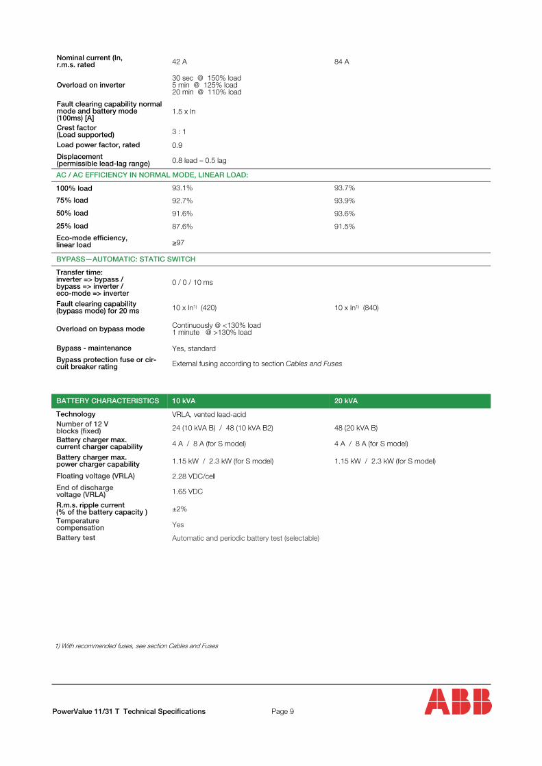
Nominal current (In, r.m.s. rated 42 A
Overload on inverter 30 sec @ 150% load 5 min @ 125% load 20 min @ 110% load
Fault clearing capability normal mode and battery mode (100ms) [A]
1.5 x In
Crest factor (Load supported) 3 : 1
Load power factor, rated 0.9
Displacement (permissible lead-lag range) 0.8 lead – 0.5 lag
84 A
AC / AC EFFICIENCY IN NORMAL MODE, LINEAR LOAD:
100% load 93.1% 93.7%
75% load 92.7% 93.9%
50% load 91.6% 93.6%
25% load 87.6% 91.5%
Eco-mode efficiency, linear load
≥97
BYPASS—AUTOMATIC: STATIC SWITCH
Transfer time: inverter => bypass / bypass => inverter / eco-mode => inverter
0 / 0 / 10 ms
Fault clearing capability (bypass mode) for 20 ms 10 x In1) (420)
Bypass - maintenance Yes, standard
Bypass protection fuse or cir-cuit breaker rating External fusing according to section Cables and Fuses
10 x In1) (840)
Overload on bypass mode Continuously @ <130% load1 minute @ >130% load
BATTERY CHARACTERISTICS 10 kVA 20 kVA
Technology VRLA, vented lead-acid
Number of 12 V blocks (fixed) 24 (10 kVA B) / 48 (10 kVA B2) 48 (20 kVA B)
Battery charger max. current charger capability 4 A / 8 A (for S model) 4 A / 8 A (for S model)
Battery charger max. power charger capability 1.15 kW / 2.3 kW (for S model) 1.15 kW / 2.3 kW (for S model)
Floating voltage (VRLA) 2.28 VDC/cell
End of discharge voltage (VRLA) 1.65 VDC
R.m.s. ripple current (% of the battery capacity ) ±2%
Temperature compensation Yes
Battery test Automatic and periodic battery test (selectable)
1) With recommended fuses, see section Cables and Fuses
PowerValue 11/31 T Technical Specifications Page 9
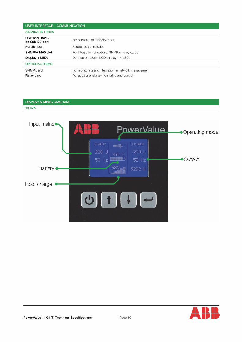
USER INTERFACE – COMMUNICATION
STANDARD ITEMS
USB and RS232 on Sub-D9 port
For service and for SNMP box
Parallel port Parallel board included
Display + LEDs
Dot matrix 128x64 LCD display + 4 LEDs
OPTIONAL ITEMS
SNMP card
For monitoring and integration in network management
Relay card For additional signal-monitoring and control
SNMP/AS400 slot For integration of optional SNMP or relay cards
DISPLAY & MIMIC DIAGRAM
10 kVA
PowerValue 11/31 T Technical Specifications
Page 10
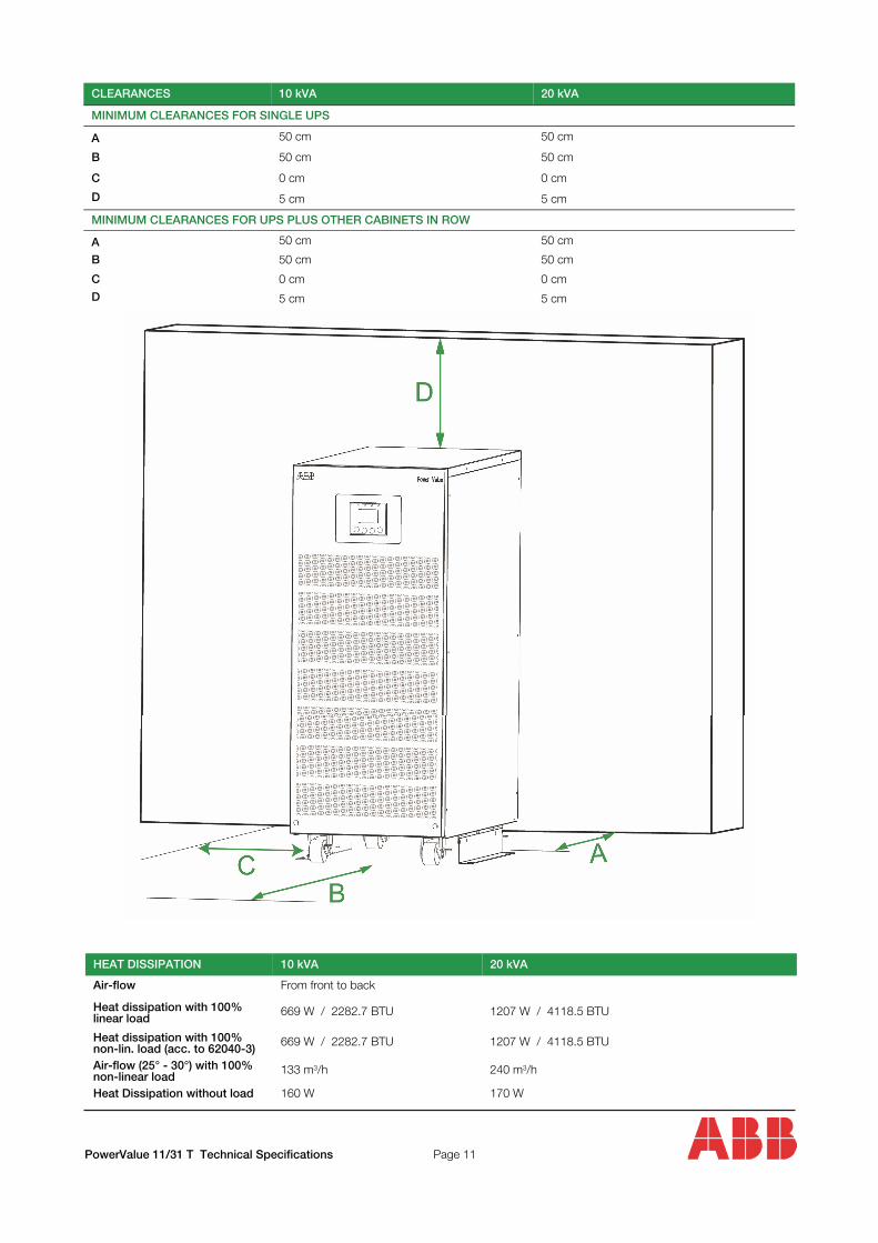
CLEARANCES 10 kVA 20 kVA
MINIMUM CLEARANCES FOR SINGLE UPS
A 50 cm 50 cm
B 50 cm 50 cm
C 0 cm 0 cm
D 5 cm 5 cm
MINIMUM CLEARANCES FOR UPS PLUS OTHER CABINETS IN ROW
A 50 cm
B 50 cm 50 cm
C 0 cm 0 cm
D 5 cm 5 cm
50 cm
PowerValue 11/31 T Technical Specifications Page 11
HEAT DISSIPATION 10 kVA 20 kVA
Air-flow From front to back
Heat dissipation with 100% linear load
669 W / 2282.7 BTU 1207 W / 4118.5 BTU
Heat dissipation with 100% non-lin. load (acc. to 62040-3)
669 W / 2282.7 BTU 1207 W / 4118.5 BTU
Air-flow (25° - 30°) with 100% non-linear load
133 m3/h 240 m3/h
Heat Dissipation without load 160 W 170 W
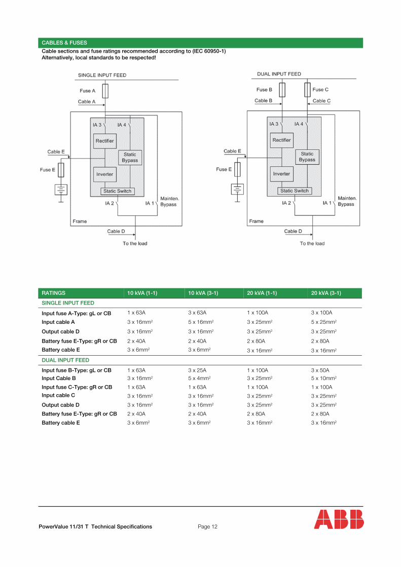
Cable sections and fuse ratings recommended according to (IEC 60950-1) Alternatively, local standards to be respected!
CABLES & FUSES
RATINGS 10 kVA (1-1) 10 kVA (3-1) 20 kVA (1-1)
SINGLE INPUT FEED
Input fuse A-Type: gL or CB 1 x 63A 3 x 63A 1 x 100A 3 x 100A Input cable A 3 x 16mm2 5 x 16mm2 3 x 25mm2 5 x 25mm2 Output cable D 3 x 16mm2 3 x 16mm2 3 x 25mm2 3 x 25mm2 Battery fuse E-Type: gR or CB 2 x 40A 2 x 40A 2 x 80A 2 x 80A Battery cable E
3 x 6mm2
3 x 6mm2
3 x 16mm2 3 x 16mm2 DUAL INPUT FEED
Input fuse B-Type: gL or CB
1 x 63A
3 x 25A
1 x 100A
3 x 50A Input Cable B 3 x 16mm2 5 x 4mm2 3 x 25mm2 5 x 10mm2 Input fuse C-Type: gR or CB 1 x 63A 1 x 63A 1 x 100A 1 x 100A Input cable C
3 x 16mm2 3 x 16mm2 3 x 25mm2 3 x 25mm2 Output cable D 3 x 16mm2 3 x 16mm2 3 x 25mm2 3 x 25mm2 Battery fuse E-Type: gR or CB 2 x 40A 2 x 40A 2 x 80A 2 x 80A Battery cable E 3 x 6mm2 3 x 6mm2 3 x 16mm2 3 x 16mm2
20 kVA (3-1)
PowerValue 11/31 T Technical Specifications
Page 12

Contact us
© Copyright ABB. All rights reserved. Specifications subject to change without notice
www.abb.com/ups