Technical Datasheet High Performance MEMS …...Inertial Measurement Unit (HPIMU) DMU30-03 Technical...
24
© Copyright 2018 Silicon Sensing Systems Limited. All rights reserved. Silicon Sensing is an Atlantic Inertial Systems, Sumitomo Precision Products joint venture company. Specification subject to change without notice. High Performance MEMS Inertial Measurement Unit (HPIMU) DMU30-03 Technical Datasheet www.siliconsensing.com Page 1 DMU30-03-0100-132 Rev 4 Applications • Hydrographic surveying • Airborne survey and mapping • INS (Inertial Navigation Systems) • AHRS (Attitude and Heading Reference System) • GPS drop-out aiding • Maritime guidance and control • GNSS (Global Navigation Satellite System) • Autonomous vehicle control and ROVs • Machine control • MEMS alternative to FOG/RLG IMUs 1 General Description DMU30 is a full six-degree-of-freedom inertial measurement unit providing precise 3-axis outputs of angular rate and acceleration, delta angle and velocity, and temperature, at 200Hz. DMU30 is the first of a new family of High Performance MEMS IMUs (HPIMU) incorporating precision VSG3Q MAX high-Q inductive resonating ring gyroscopes and capacitive accelerometers. DMU30 represents a realistic, alternative to established FOG/RLG based IMUs due to its exceptional bias stability and low noise characteristics, yet it is comparatively compact, lightweight and offers low cost of ownership. Designed speci fically to meet the growing demand from high-end commercial and industrial market applications for a ‘tactical’ grade non-ITAR IMU, DMU30 utilises Silicon Sensing’s class leading MEMS inertial sensors integrated and calibrated using an in-house state-of-the-art test facility. HPIMU development takes advantage of Silicon Sensing’s wide-ranging multi sensor technologies in a unique architecture to achieve a highly versatile IMU design. Future developments will feature GPS, magnetic and ambient pressure sensing, north finding and AHRS functions. Features • Precision 6-DOF MEMS Inertial Measurement Unit • Silicon Sensing’s latest VSG3Q MAX inductive gyro and capacitive accelerometer MEMS • Excellent Bias Instability and Random Walk Angular - 0.1°/hr, 0.02°/hr Linear - 15μg, 0.05m/s/hr • Non-ITAR • Compact and lightweight - 68.5 x 61.5 x 65.5H (mm), 345g • Internal power conditioning to accept 4.75V to 36V input voltage • RS422 interfaces • -40°C to +85°C operating temperature range • Sealed aluminium housing • RoHS compliant • In-house manufacture from MEMS fabrication to IMU calibration • Evaluation kit and integration resources available • First class customer technical support • Future developments and expansion capability Multi sensor MEMS blending Low power ‘sleep’ mode Additional sensor integration - GPS/ Magnetometer/Barometer North finding mode AHRS functionality Other interface protocols and specifications Custom and host application integration
Transcript of Technical Datasheet High Performance MEMS …...Inertial Measurement Unit (HPIMU) DMU30-03 Technical...

© Copyright 2018 Silicon Sensing Systems Limited. All rights reserved. Silicon Sensing is an Atlantic Inertial Systems, Sumitomo Precision Products joint venture company.Specifi cation subject to change without notice.
High Performance MEMSInertial Measurement Unit (HPIMU)
DMU30-03 Technical Datasheet
www.siliconsensing.com
Page 1DMU30-03-0100-132 Rev 4
Applications• Hydrographic surveying• Airborne survey and mapping• INS (Inertial Navigation Systems)• AHRS (Attitude and Heading Reference System)• GPS drop-out aiding• Maritime guidance and control• GNSS (Global Navigation Satellite System)• Autonomous vehicle control and ROVs • Machine control• MEMS alternative to FOG/RLG IMUs
1 General DescriptionDMU30 is a full six-degree-of-freedom inertial measurement unit providing precise 3-axis outputs of angular rate and acceleration, delta angle and velocity, and temperature, at 200Hz.
DMU30 is the fi rst of a new family of High Performance MEMS IMUs (HPIMU) incorporating precision VSG3QMAX
high-Q inductive resonating ring gyroscopes and capacitive accelerometers.
DMU30 represents a realistic, alternative to established FOG/RLG based IMUs due to its exceptional bias stability and low noise characteristics, yet it is comparatively compact, lightweight and offers low cost of ownership.
Designed specifi cally to meet the growing demand from high-end commercial and industrial market applications for a ‘tactical’ grade non-ITAR IMU, DMU30 utilises Silicon Sensing’s class leading MEMS inertial sensors integrated and calibrated using an in-house state-of-the-art test facility.
HPIMU development takes advantage of Silicon Sensing’s wide-ranging multi sensor technologies in a unique architecture to achieve a highly versatile IMU design. Future developments will feature GPS, magnetic and ambient pressure sensing, north fi nding and AHRS functions.
Features• Precision 6-DOF MEMS Inertial Measurement Unit• Silicon Sensing’s latest VSG3QMAX inductive gyro and capacitive accelerometer MEMS• Excellent Bias Instability and Random Walk Angular - 0.1°/hr, 0.02°/hr Linear - 15μg, 0.05m/s/hr• Non-ITAR• Compact and lightweight - 68.5 x 61.5 x 65.5H (mm), 345g• Internal power conditioning to accept 4.75V to 36V input voltage• RS422 interfaces• -40°C to +85°C operating temperature range• Sealed aluminium housing• RoHS compliant• In-house manufacture from MEMS fabrication to IMU calibration• Evaluation kit and integration resources available• First class customer technical support• Future developments and expansion capability Multi sensor MEMS blending Low power ‘sleep’ mode Additional sensor integration - GPS/ Magnetometer/Barometer North fi nding mode AHRS functionality Other interface protocols and specifi cations Custom and host application integration

© Copyright 2018 Silicon Sensing Systems Limited. All rights reserved. Silicon Sensing is an Atlantic Inertial Systems, Sumitomo Precision Products joint venture company.Specifi cation subject to change without notice.
High Performance MEMSInertial Measurement Unit (HPIMU)
DMU30-03 Technical Datasheet
www.siliconsensing.com
61.5
MA
X
68.5 MAX64 MAX
65.5 MAX 57
50
5.5
5.5 5
3
63.0
23.222.2
Figure 1.1 DMU30 Functional Block Diagram
Figure 1.2 DMU30 Unit Overall Dimensions
DMU30-03-0100-132 Rev 4Page 2
Regulators
144.75 to 36V
Power Return
Tx_HiTx_LoRx_LoRx_Hi
AUX -AUX +TOV -TOV +
Run ModeTOVProg
Reset
15
8765
4321
13121110
Chassis 9
RS422Driver
Analogue toDigital
Converters
Vref
TemperatureSensors
Accelerometer(+Y, -Z)
Accelerometer(+X, +Z)
Accelerometer(-X, -Y)
HighPerformance
Gyro X
HighPerformance
Gyro Y
HighPerformance
Gyro Z
Wide BandwidthHigh Dynamic
RangeGyro X
Wide BandwidthHigh Dynamic
RangeGyro Y
Wide BandwidthHigh Dynamic
RangeGyro Z
MPU
C.G. 18768
All dimensions in millimetres.

© Copyright 2018 Silicon Sensing Systems Limited. All rights reserved. Silicon Sensing is an Atlantic Inertial Systems, Sumitomo Precision Products joint venture company.Specifi cation subject to change without notice.
High Performance MEMSInertial Measurement Unit (HPIMU)
DMU30-03 Technical Datasheet
www.siliconsensing.com
2 Ordering Information
Item DescriptionOverall
DimensionsPart Number
mm
DMU30-03 IMU
High PerformanceMEMS Inertial Measurement
Unit68.5 x 61.5 x 65.5H DMU30-03-0100
DMU30 Evaluation Kit
Customer Evaluation Kit (EVK) comprising a
RS422 to USB Connector, USB Driver and Data Logging
Software, Cables and Connectors, Instruction Manual
(DMU30 is NOT included)
Not Applicable DMU30-00-0500
DMU30 Mating Connector
Mating connectorplug and cable for DMU30
Length 450mmGlenair
MWDM2L-15P-6E5-18or equivalent
Page 3DMU30-03-0100-132 Rev 4

© Copyright 2018 Silicon Sensing Systems Limited. All rights reserved. Silicon Sensing is an Atlantic Inertial Systems, Sumitomo Precision Products joint venture company.Specifi cation subject to change without notice.
High Performance MEMSInertial Measurement Unit (HPIMU)
DMU30-03 Technical Datasheet
www.siliconsensing.com
3 Specifi cation
Parameter Minimum Typical Maximum Notes
Angular (Roll, Pitch, Yaw)
Dynamic Range (°/s) -490 – +490Clamped at ±495°/sduring over-range
Scale Factor Error (ppm)Over Life
-700(-1500)
±500+700
(+1500)
Up to ±200°/s(over life)
(between ±200°/s and ±490°/s)
Scale Factor Non-Linearity Error (ppm)
-500(-1500)
±100(±500)
+500(+1500)
Up to ±200°/sfactory fresh test
(between ±200°/s and ±490°/s)
Bias (°/hr) -20 ±15 +20Over operating
temperature rangefactory fresh test
Bias Instability (°/h) – < 0.1 0.2As measured using theAllan Variance method.
Random Walk ( °/h) – < 0.02 0.04
Bias Repeatability (°/h) – 20 100
Gyro Cross Coupling (%) -0.40 ±0.20 +0.40Over operating
temperature range
Sensor Level Bandwidth (Hz) – 150 – -3dB point
IMU Level Bandwidth (Hz) >77 – – -3dB point
Noise (°/s rms) – 0.05 0.1 Wide band noise
VRE (°/s/g2 rms) -0.006 ±0.002 +0.0064.2g rms stimulus20Hz to 2,000Hz
g Sensitivity (°/hr/g) -0.1 ±0.05 +0.1 Tested over ±10g
DMU30-03-0100-132 Rev 4Page 4
√(Biaswarmup)2 + (Biastoto)2 + (Biasageing)2 + (Biastemperature)2
Bias Repeatability =
© Copyright 2018 Silicon Sensing Systems Limited. All rights reserved. Silicon Sensing is an Atlantic Inertial Systems, Sumitomo Precision Products joint venture company.Specifi cation subject to change without notice.
High Performance MEMSInertial Measurement Unit (HPIMU)
DMU30-03 Technical Datasheet
www.siliconsensing.com
Page 5DMU30-03-0100-132 Rev 4
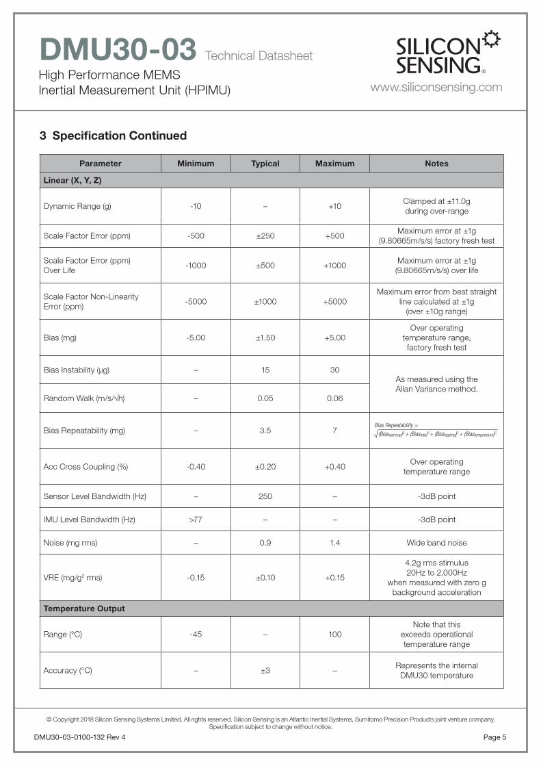
3 Specifi cation Continued
Parameter Minimum Typical Maximum Notes
Linear (X, Y, Z)
Dynamic Range (g) -10 – +10Clamped at ±11.0gduring over-range
Scale Factor Error (ppm) -500 ±250 +500Maximum error at ±1g
(9.80665m/s/s) factory fresh test
Scale Factor Error (ppm)Over Life
-1000 ±500 +1000Maximum error at ±1g (9.80665m/s/s) over life
Scale Factor Non-LinearityError (ppm)
-5000 ±1000 +5000Maximum error from best straight
line calculated at ±1g(over ±10g range)
Bias (mg) -5.00 ±1.50 +5.00Over operating
temperature range,factory fresh test
Bias Instability (μg) – 15 30As measured using theAllan Variance method.
Random Walk (m/s/h) – 0.05 0.06
Bias Repeatability (mg) – 3.5 7
Acc Cross Coupling (%) -0.40 ±0.20 +0.40Over operating
temperature range
Sensor Level Bandwidth (Hz) – 250 – -3dB point
IMU Level Bandwidth (Hz) >77 – – -3dB point
Noise (mg rms) – 0.9 1.4 Wide band noise
VRE (mg/g2 rms) -0.15 ±0.10 +0.15
4.2g rms stimulus20Hz to 2,000Hz
when measured with zero gbackground acceleration
Temperature Output
Range (°C) -45 – 100Note that this
exceeds operationaltemperature range
Accuracy (°C) – ±3 –Represents the internal
DMU30 temperature
√(Biaswarmup)2 + (Biastoto)2 + (Biasageing)2 + (Biastemperature)2
Bias Repeatability =
© Copyright 2018 Silicon Sensing Systems Limited. All rights reserved. Silicon Sensing is an Atlantic Inertial Systems, Sumitomo Precision Products joint venture company.Specifi cation subject to change without notice.
High Performance MEMSInertial Measurement Unit (HPIMU)
DMU30-03 Technical Datasheet
www.siliconsensing.com
DMU30-03-0100-132 Rev 4Page 6
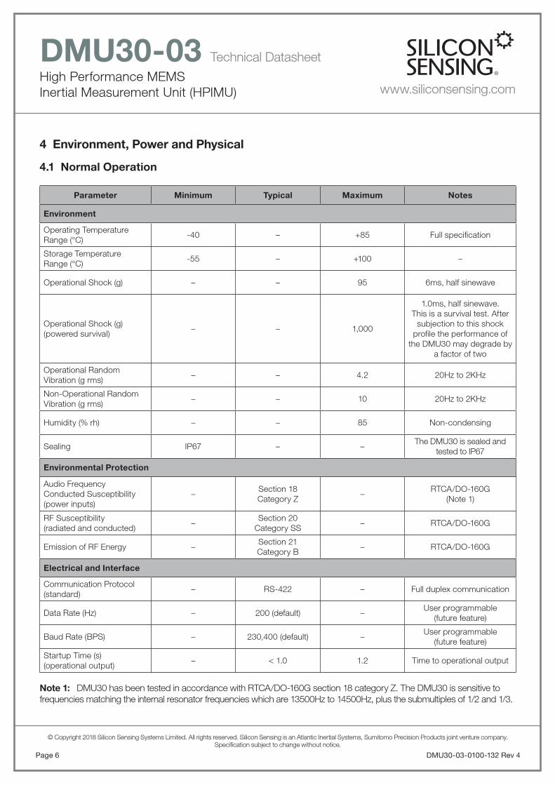
4 Environment, Power and Physical
4.1 Normal Operation
Parameter Minimum Typical Maximum Notes
Environment
Operating Temperature Range (°C)
-40 – +85 Full specifi cation
Storage TemperatureRange (°C)
-55 – +100 –
Operational Shock (g) – – 95 6ms, half sinewave
Operational Shock (g)(powered survival)
– – 1,000
1.0ms, half sinewave.This is a survival test. After
subjection to this shock profi le the performance of
the DMU30 may degrade by a factor of two
Operational RandomVibration (g rms)
– – 4.2 20Hz to 2KHz
Non-Operational RandomVibration (g rms)
– – 10 20Hz to 2KHz
Humidity (% rh) – – 85 Non-condensing
Sealing IP67 – –The DMU30 is sealed and
tested to IP67
Environmental Protection
Audio Frequency Conducted Susceptibility(power inputs)
–Section 18Category Z
–RTCA/DO-160G
(Note 1)
RF Susceptibility(radiated and conducted)
–Section 20
Category SS– RTCA/DO-160G
Emission of RF Energy –Section 21Category B
– RTCA/DO-160G
Electrical and Interface
Communication Protocol (standard)
– RS-422 – Full duplex communication
Data Rate (Hz) – 200 (default) –User programmable
(future feature)
Baud Rate (BPS) – 230,400 (default) –User programmable
(future feature)
Startup Time (s)(operational output)
– < 1.0 1.2 Time to operational output
Note 1: DMU30 has been tested in accordance with RTCA/DO-160G section 18 category Z. The DMU30 is sensitive to frequencies matching the internal resonator frequencies which are 13500Hz to 14500Hz, plus the submultiples of 1/2 and 1/3.

© Copyright 2018 Silicon Sensing Systems Limited. All rights reserved. Silicon Sensing is an Atlantic Inertial Systems, Sumitomo Precision Products joint venture company.Specifi cation subject to change without notice.
High Performance MEMSInertial Measurement Unit (HPIMU)
DMU30-03 Technical Datasheet
www.siliconsensing.com
Page 7DMU30-03-0100-132 Rev 4
4.2 Absolute Minimum/Maximum Ratings
Minimum Maximum
Electrical:
Vdd Reverse voltage protected +37V
ESD protection –IEC 61000-4-2
with chassis externally connected to 0V
Life:
Operational life 5 years –
MTTF 20,000 hours –
Notes:
Improper handling, such as dropping onto hard surfaces, can generate every high shock levels in excess of 10,000g. The resultant stresses can cause permanent damage to the sensor.
Exposure to the Absolute Maximum Ratings for extended periods may affect performance and reliability.
Parameter Minimum Typical Maximum Notes
Startup Time (s)(full performance)
– – 20Time to full performance(mounting dependent)
Power (watts) – < 3 4With 120 RS422termination resistor
Supply Voltage (V) +4.75 +12 +36
Unit is calibrated at 12VNote that operation at 4.75Vrequires a low impedance
supply with shortinterconnects
Physical
Size (mm) – 68.5 x 61.5 x 65.5H – –
Mass (grams) – 345g 350g –
Notes:
DMU30 is designed for immersion in water (IP67). To maintain integrity around the connector, it is essential thatthe mating connector is a sealed type, or a suitable sealing compound should be applied around the connectors.
The in-rush current required for start up increases with decreasing supply voltage. Therefore, for low supply voltagesa supply with a low source impedance is required. Also short cables are recommended.
4.1 Normal Operation Continued
© Copyright 2018 Silicon Sensing Systems Limited. All rights reserved. Silicon Sensing is an Atlantic Inertial Systems, Sumitomo Precision Products joint venture company.Specifi cation subject to change without notice.
High Performance MEMSInertial Measurement Unit (HPIMU)
DMU30-03 Technical Datasheet
www.siliconsensing.com
DMU30-03-0100-132 Rev 4Page 8
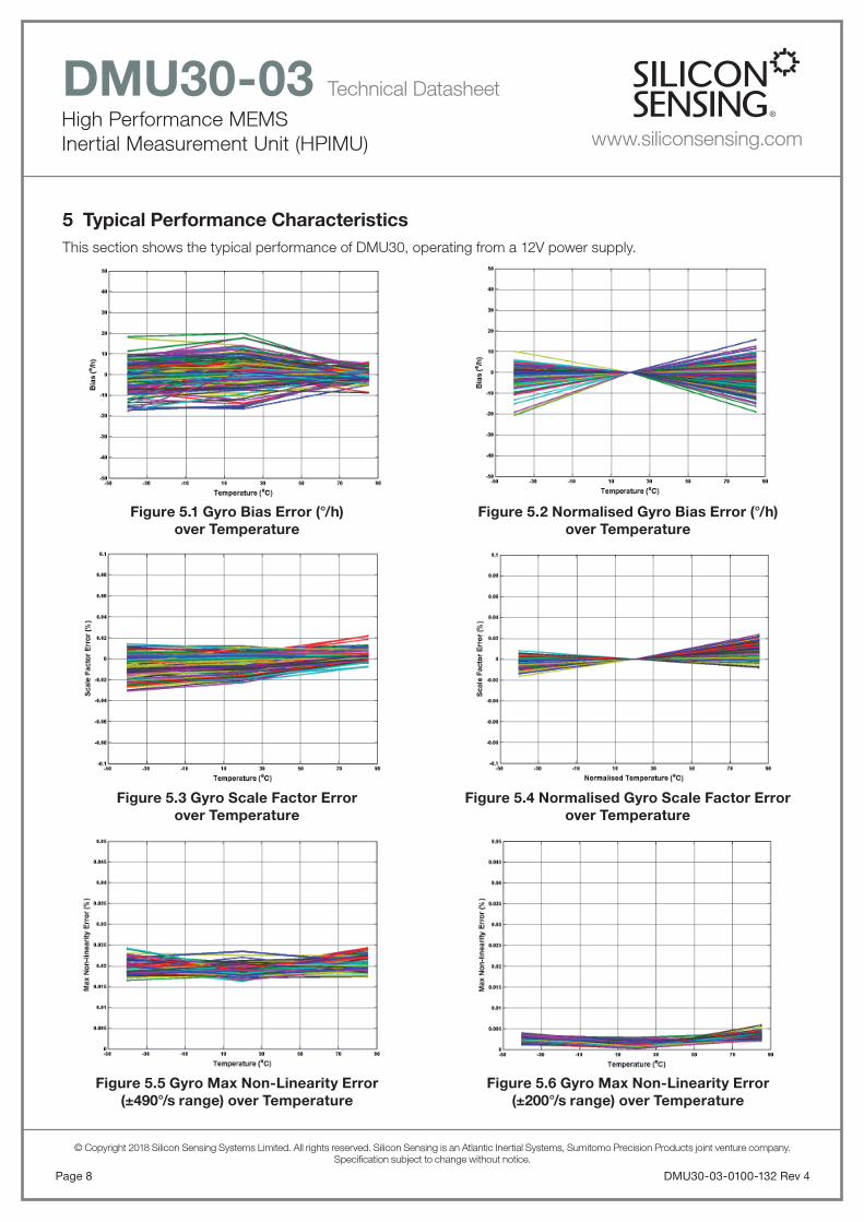
5 Typical Performance CharacteristicsThis section shows the typical performance of DMU30, operating from a 12V power supply.
Figure 5.3 Gyro Scale Factor Errorover Temperature
Figure 5.5 Gyro Max Non-Linearity Error(±490°/s range) over Temperature
Figure 5.4 Normalised Gyro Scale Factor Errorover Temperature
Figure 5.6 Gyro Max Non-Linearity Error(±200°/s range) over Temperature
Figure 5.1 Gyro Bias Error (°/h)over Temperature
Figure 5.2 Normalised Gyro Bias Error (°/h)over Temperature
© Copyright 2018 Silicon Sensing Systems Limited. All rights reserved. Silicon Sensing is an Atlantic Inertial Systems, Sumitomo Precision Products joint venture company.Specifi cation subject to change without notice.
High Performance MEMSInertial Measurement Unit (HPIMU)
DMU30-03 Technical Datasheet
www.siliconsensing.com
Page 9DMU30-03-0100-132 Rev 4
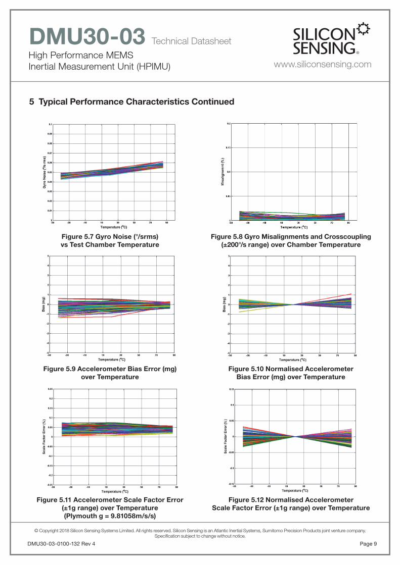
5 Typical Performance Characteristics Continued
Figure 5.9 Accelerometer Bias Error (mg)over Temperature
Figure 5.11 Accelerometer Scale Factor Error(±1g range) over Temperature(Plymouth g = 9.81058m/s/s)
Figure 5.10 Normalised AccelerometerBias Error (mg) over Temperature
Figure 5.12 Normalised AccelerometerScale Factor Error (±1g range) over Temperature
Figure 5.7 Gyro Noise (°/srms)vs Test Chamber Temperature
Figure 5.8 Gyro Misalignments and Crosscoupling(±200°/s range) over Chamber Temperature

© Copyright 2018 Silicon Sensing Systems Limited. All rights reserved. Silicon Sensing is an Atlantic Inertial Systems, Sumitomo Precision Products joint venture company.Specifi cation subject to change without notice.
High Performance MEMSInertial Measurement Unit (HPIMU)
DMU30-03 Technical Datasheet
www.siliconsensing.com
5 Typical Performance Characteristics Continued
Figure 5.15 current Consumption vs Chamber Temperature (12V supply)
Figure 5.16 DMU30 Temperature OutputDifference (°/C) vs Test Temperature (self heating)
Figure 5.17 Gyro Allan Variance
Figure 5.13 Accelerometer Noise vsTest Chamber Temperature
Figure 5.14 Accelerometer Misalignments and Crosscoupling over Temperature
DMU30-03-0100-132 Rev 4Page 10
Figure 5.18 Gyro In Run Stability

© Copyright 2018 Silicon Sensing Systems Limited. All rights reserved. Silicon Sensing is an Atlantic Inertial Systems, Sumitomo Precision Products joint venture company.Specifi cation subject to change without notice.
High Performance MEMSInertial Measurement Unit (HPIMU)
DMU30-03 Technical Datasheet
www.siliconsensing.com
Page 11DMU30-03-0100-132 Rev 4
5 Typical Performance Characteristics Continued
Figure 5.21 Accelerometer Allan Variance
Figure 5.23 Accelerometer Spectral Data
Figure 5.22 Accelerometer In Run Stability
Figure 5.24 Accelerometer Cumulative Noise
Figure 5.20 Gyro Cumulative NoiseFigure 5.19 Gyro Spectral Data

© Copyright 2018 Silicon Sensing Systems Limited. All rights reserved. Silicon Sensing is an Atlantic Inertial Systems, Sumitomo Precision Products joint venture company.Specifi cation subject to change without notice.
High Performance MEMSInertial Measurement Unit (HPIMU)
DMU30-03 Technical Datasheet
www.siliconsensing.com
DMU30-03-0100-132 Rev 4Page 12
6 Glossary of Terms
ADC Analogue to Digital Converter
ARW Angle Random Walk
AWG American Wire Gauge
BPS Bits Per Second (or Baud Rate)
BW Bandwidth
C Celsius or Centigrade
DAC Digital to Analogue Converter
DPH Degrees Per Hour
DPS Degrees Per Second
DRIE Deep Reactive Ion Etch
EMC Electro-Magnetic Compatibility
ESD Electro-Static Damage
F Farads
h Hour
HBM Human Body Model
HPIMUHigh Performance MEMS Inertial Measurement Unit
Hz Hertz, Cycles Per Second
K Kilo
MDS Material Datasheet
MEMS Micro-Electro Mechanical Systems
mV Milli-Volts
NEC Not Electrically Connected
NL Scale Factor Non-Linearity
OEM Original Equipment Manufacturer
OT Over Temperature
PD Primary Drive
PP Primary Pick-Off
RC Resistor and Capacitor fi lter
RT Room Temperature
s Seconds
SF Scale Factor
SMT Surface Mount Technology
SOG Silicon On Glass
SD Secondary Drive
SP Secondary Pick-Off
TBA To Be Advised
TBC To Be Confi rmed
TBD To Be Determined
V Volts
7 InterfacePhysical and electrical inter-connect and RS422 message information
7.1 Electrical Interface
Figure 7.1 Required Connections for RS422 Communications with DMU30
7.2 Physical Interface
Figure 7.2 DMU30 Socket Connector
4.75 to 36V
POWER RETURN
AUX+ TOV+
AUX- TOV-
Rx_Lo**
* These connections are optional and can be left not connected.
** These inputs include a 120Ω termination resistor. These inputs can therefore be left not connected.
143 4 1 2
6
5
7
10
13
12
15 Chassis
9
8 DMU30SYSTEMHOST
Rx_Hi**
RESET*
RUN MODE*
TOV*
0V
Tx_Lo
Tx_Hi
C.G. 18734
C.G. 18735
1
9 15
15 Way Micro-Miniature Connector Type DCCM-15S
8

© Copyright 2018 Silicon Sensing Systems Limited. All rights reserved. Silicon Sensing is an Atlantic Inertial Systems, Sumitomo Precision Products joint venture company.Specifi cation subject to change without notice.
High Performance MEMSInertial Measurement Unit (HPIMU)
DMU30-03 Technical Datasheet
www.siliconsensing.com
Page 13DMU30-03-0100-132 Rev 4
7.3 Connector Specifi cationDMU30 uses a 15 way socket connector which is the micro-miniature ‘D’ type range of connectors, produced by Cinch, Glenair and others.
The DMU30 plug mating connector is a 15 way plug, for example DCCM-15P (DCCM-15P6E518).
Silicon Sensing can supply a mating plug and cable to interface to DMU30 or they are available from electronic component distributors.
7.4 Pin Information
Pin Label SignalIn/Out
Nominal Range
Absolute Max
1 TOV+Time of Validity positive
differential positive outputO ±5V ±15V
2 TOV-Time of Validity positive
differential negative outputO ±5V ±15V
3 AUX+Auxiliary signal positive
differential inputI
-9V to +9V
-9V to +9V
4 AUX-Auxiliary signal negative
differential inputI
-9V to +9V
-9V to +9V
5 Rx_HiThe positive receive
connection required for the RS422 communication
I ±5V ±15V
6 Rx_LoThe negative receive
connection required for the RS422 communication
I ±5V ±15V
7 Tx_LoThe negative transmit
connection required for the RS422 communication
O ±5V ±15V
8 TX_HiThe positive transmit
connection required for the RS422 communication
O ±5V ±15V
9 Chassis Chassis I 0V +6V
10 ResetMicroprocessor reset. Pin is pulled low to reset the
device. I
0V to +5V
-0.3V to +7.3V
11Factory
Use
Used by SSSL for program-ming purposes and should
not be interfaced withN/A
0V to +5V
-0.3V to +7.3V
12 TOVTime of Validity(see section 7.7)
O0V to +5V
-0.3V to +7.3V
13Run
Mode
Device Enable/Disable. Pin is pulled high or not connected to enable the device. Pin is pulled low to disable the device.
Suggested implementation using TTL logic
I0V to +5V
-0.3V to +7.3V
14 +VoltsInput voltage to the DMU30. Can be between 4.75V and 36V with respect to GND
I+4.75V to +36V
-37V to +37V
15 0V Power return for the DMU30 I – –
Table 7.1 Pin Information
7.5 ChassisThe chassis of DMU30 is not internally connected to the 0V power return. The chassis shall be electrically connected to the system 0V by a low impedance connection. Note that the base of the DMU30 has not been anodised in order to facilitate this connection.If the mount is isolated, Pin 9 should be used to ground the chassis.
7.6 Communications with DMU30The Run Mode pin on the connector is used to control the output from the DMU30. The “Free Run” or “Enabled” mode is active when the Pin is fl oating (not connected), and the output will be enabled.
The DMU30 output is disabled when the “Run Mode” Pin is pulled low. Note that the Rx_Hi and Rx_Lo lines include a 120 termination resistor.
7.7 Operational Message OutputThe Output Message is output on a RS422 Serial output at 230,400 baud using a non-return to zero protocol. Note the RS422 lines are not trislated between messages Each byte contains a start bit (logic 0), 8 data bits and 2 stop bits (logic 1). Data is output in big endian format by default.
Data is output at a rate of 200 messages per second.
Each message contains 22 words (44 bytes) as described in Table 7.2. The message is transmitted if the “Run Mode” Pin is fl oating/HIGH.
If the “Run Mode” Pin changes to a LOW (Disable output), while the message is being transmitted, the message is completed before the output is disabled.
7.8 Sensor Sampling and SynchronisationThe DMU30 includes a ‘Time of Validity (TOV)’ output for synchronisation purposes.
The ‘TOV’ on the connector is normally set HIGH. It is set low, for 1.0ms, half way through the sampling sensor process. It therefore indicates the reference point in time when the data output in the next message was collected. The ‘TOV’ pulses are therefore seen on the connector at 200Hz.

© Copyright 2018 Silicon Sensing Systems Limited. All rights reserved. Silicon Sensing is an Atlantic Inertial Systems, Sumitomo Precision Products joint venture company.Specifi cation subject to change without notice.
High Performance MEMSInertial Measurement Unit (HPIMU)
DMU30-03 Technical Datasheet
www.siliconsensing.com
DMU30-03-0100-132 Rev 4Page 14
Figure 7.3 Timing Diagram
Time of Validity Parameters Requirement
Time of Validity Signal Frequency 200.2Hz
TOV Logic Active Low
TOV Pulse Width 1ms
TOV Declared Accuracy <0.5ms
TOV Jitter <50μs
Delay to Start of Message fromTOV Low
<10ms(7.9ms Typical)
Format
RS422 Differential from Pins 1 and 2, Single Ended from
Pin 12
Table 7.2 Time of Validity Parameters
The message from the DMU30 is transmitted after the ‘Time of Validity’. This enables the external equipment to synchronise with the time when the Inertial Data was valid.
7.9 Auxiliary InputA differential auxiliary input is provided and is capable of accepting voltage inputs of up to ±9V.
7.10 Operational Message Defi nitionsThe data output message has the content and sequence as shown in the table below:
Item Word Data Item Value / Unit
0 0 Header 16 Bit, 0x55AA
1 1 Message Count16 Bit, 0 to 65535
decimal
2 2-3 Axis X Rate32 Bit Single Precision
FP, ( /̊s)
3 4-5Axis X
Acceleration32 Bit Single Precision
FP, (g)
4 6-7 Axis Y Rate32 Bit Single Precision
FP, ( /̊s)
5 8-9Axis Y
Acceleration32 Bit Single Precision
FP, (g)
6 10-11 Axis Z Rate 32 Bit Single Precision
FP, ( /̊s)
7 12-13Axis Z
Acceleration32 Bit Single Precision
FP, (g)
8 14-15 Aux Input Voltage32 Bit Single Precision
FP, (volts)
9 16-17Average IMUTemperature
32 Bit Single Precision FP, (˚C)
10 18System Startup
BIT Flags16 Bit decimal value
11 19System Operation
BIT Flags16 Bit decimal value
12 20Error Operation
BIT Flags16 Bit decimal value
13 21 Checksum16 Bit 2’s Complement of the 16 Bit Sum of the Previous 0-18 data items
Table 7.3 Operational Message Data Output Defi nitions
1.0ms
TOV/SYNCSignal
4.995ms
7.9ms 2.1ms
TOV1
TOV2
TOV3
TOV4
TOV1Data
TOV0Data
C.G.18828
RS422 DataOutput
TOV2Data

© Copyright 2018 Silicon Sensing Systems Limited. All rights reserved. Silicon Sensing is an Atlantic Inertial Systems, Sumitomo Precision Products joint venture company.Specifi cation subject to change without notice.
High Performance MEMSInertial Measurement Unit (HPIMU)
DMU30-03 Technical Datasheet
www.siliconsensing.com
Page 15DMU30-03-0100-132 Rev 4
7.11.3 System Error Indication BIT Flags
BIT BIT Flag Error Indication
0 Axis X Rate
1 Axis X Acceleration
2 Axis Y Rate
3 Axis Y Acceleration
4 Axis Z Rate
5 Axis Z Acceleration
6 Aux Input Voltage
7 Average IMU Temperature
8 Reserved
9 Reserved
10 Reserved
11 Reserved
12 Reserved
13 Reserved
14 Reserved
15 Reserved
7.11 System BIT FlagsBuilt in Test functions are indicated during start up and operation. The Bit Flag Error indication word provides details of affected axes if a fault is detected.
7.11.1 System Start up BIT Flags
BIT System Start Up Flags
0 Extendable Checksum Fail
1 NVM Coeffi cient Checksum Fail
2 Sensor Start Up Error
3 Internal Processor Error
4 Invalid NVM Coeffi cient
5 Reserved
6 Reserved
7 Reserved
8 Reserved
9 Reserved
10 Reserved
11 Reserved
12 Reserved
13 Reserved
14 Reserved
15 Reserved
7.11.2 System Operation BIT Flags
BIT System Operation Flags
0 Voltage Regulator Range Error
1 Scheduler Slot Extended
2 Output Message Missed
3 Internal Processor Error
4 Sensor Operation Error
5 Output Over Range
6 Accelerometer Plausibility Error
7 Reserved
8 Reserved
9 Reserved
10 Reserved
11 Reserved
12 Reserved
13 Reserved
14 Reserved
15 Reserved

© Copyright 2018 Silicon Sensing Systems Limited. All rights reserved. Silicon Sensing is an Atlantic Inertial Systems, Sumitomo Precision Products joint venture company.Specifi cation subject to change without notice.
High Performance MEMSInertial Measurement Unit (HPIMU)
DMU30-03 Technical Datasheet
www.siliconsensing.com
DMU30-03-0100-132 Rev 4Page 16
8 Design Tools and Resources Available
Item Description of Resource Part Number Order/Download
DMU30 Brochure: A one page sales brochure describing the key features of the DMU30 Inertial Measurement Unit.
DMU30-01-0100-131Download
(www.siliconsensing.com)
DMU30-03 Datasheet: Full technical information on all DMU30 Dynamic Measurement Unit part number options. Specifi cation and other essential information for assembling and interfacing to DMU30 Inertial Measurement Unit, and getting the most out of it.
DMU30-03-0100-132Download
(www.siliconsensing.com)
DMU30 Evaluation Kit: Delivered with an RS422 to USB interface, plug-and-play real time display and logging software and two interface cabling solutions DMU30 unit NOT included.
DMU30-00-0500Order
(www.siliconsensing.com)([email protected])
DMU30 Presentation: A useful presentation describing the features, construction, principles of operation and applications for the DMU30 Inertial Measurement Unit.
—Download
(www.siliconsensing.com)
Solid Model CAD fi les for DMU30 InertialMeasurement Unit:Available in .STP and .IGS fi le formats.
DMU30-00-0100-408Download
(www.siliconsensing.com)
DMU30 Plug and Cable: A mating plug and450mm long cable.
GlenairMWDM2L-15P-6E5-18
or equivalent
Available from RSPart No. 612-6489
DMU30 Installation Drawing: CAD fi le containing host interface geometry. Available in .STP and .IGS fi le formats.
DMU30-00-0100-403Download
(www.siliconsensing.com)
RoHS compliance statement for DMU30 : DMU30 is fully compliant with RoHS. For details of the materials used in the manufacture please refer to the MDS Report.
—Download
(www.siliconsensing.com)
57
50
5.5
5.5 5
3
63.0

© Copyright 2018 Silicon Sensing Systems Limited. All rights reserved. Silicon Sensing is an Atlantic Inertial Systems, Sumitomo Precision Products joint venture company.Specifi cation subject to change without notice.
High Performance MEMSInertial Measurement Unit (HPIMU)
DMU30-03 Technical Datasheet
www.siliconsensing.com
Page 17DMU30-03-0100-132 Rev 4
8.1 DMU30 Evaluation KitThe DMU30 Evaluation Kit enables the output data from the DMU30 to be viewed and logged for testing and evaluation purposes.
Figure 8.1 DMU30 Evaluation Kit
8.1.1 DMU30 Evaluation Kit ContentsThe DMU30 Evaluation Kit (part number DMU30-00-0500) contains the following:
• MEV RS485i to USB converter.
• CD containing the MEV drivers.
• USB memory stick containing the data logging software.
• Mating plug and cable.
• User manual.
Note: DMU30 is NOT included in the evaluation kit.
8.1.2 System RequirementsThe DMU30 Evaluation Kit requires a PC with a USB port. The requirements for the PC are as follows:
• Microsoft® Vista®, Windows 7, Windows 8 or Windows 10, Operating Systems. The software has not been tested on any other Operating System and therefore correct functionality cannot be guaranteed.
• Minimum of 500Mb of RAM.
• 500Mb of free hard drive space plus space for logged data (typical data rate ≈ 50kbit/s).
• High power or self-powered USB 2.0 Port.
9 Part MarkingsDMU30 is supplied with an adhesive label attached.The label displays readable DMU30 part and part identifi cation numbers.
The part identifi cation number is a numeric code;
YYWWXXXX CC where:
YY = Manufacturing year number
WW = Manufacturing week number
XXXX = Serial number
CC = Revision
A 4x4 data matrix barcode containing the part identifi cation number is also displayed on the label.
Figure 9.1 DMU30 Label
DMU30PT NO. DMU30-03-0100SER NO. YYWWXXXX CC
MADE IN PLYMOUTH UK

© Copyright 2018 Silicon Sensing Systems Limited. All rights reserved. Silicon Sensing is an Atlantic Inertial Systems, Sumitomo Precision Products joint venture company.Specifi cation subject to change without notice.
High Performance MEMSInertial Measurement Unit (HPIMU)
DMU30-03 Technical Datasheet
www.siliconsensing.com
DMU30-03-0100-132 Rev 4Page 18
Figure 10.1 DMU30 Installation Drawing
10 Installation DetailsFigures 10.1 show the installation drawing for the DMU30.
The DMU30 is designed for 4 point mounting using M4.0 screws. During calibration alignment is achieved using two external reference dowel holes on the base of the DMU30. The dowel holes are designed to be used with two Ø3mm (in accordance with BS EN ISO 8734 or BS EN ISO 2338) dowel pins provided by the host.
The DMU30 mounting screw torque settings will be dependent on the host application; it will for example vary depending on the specifi cation of the screw, the material of the host structure and whether a locking compound is used. When securing a DMU30 to the host system using steel M4.0 screws and a thread locking compound the suggested torque setting is 0.2Nm for securing to an aluminium host structure. This information is provided for guidance purposes only, the actual torque settings are the responsibility of the host system designer.
61.5
MA
X
68.5 MAX
Note: A 3D CAD data file DMU30-00-0100-408_ISS_2.stp contained in zip. File: DMU30-00-0100-408 Issue 2 for this Part. Information on drawing takes precedence.
64 MAX65.5 MAX 57
505.5
5.5 5
3
63.0
23.222.2
4x Ø 4.5
3.0253.010
4x R8
SLOT Ø
Ø 0.2 M
3.5 DP MIN
Ø 0.2 M3.0253.010Ø
3.5 DP MIN
Ø 0.2 M
All dimensions in millimetres.
© Copyright 2018 Silicon Sensing Systems Limited. All rights reserved. Silicon Sensing is an Atlantic Inertial Systems, Sumitomo Precision Products joint venture company.Specifi cation subject to change without notice.
High Performance MEMSInertial Measurement Unit (HPIMU)
DMU30-03 Technical Datasheet
www.siliconsensing.com
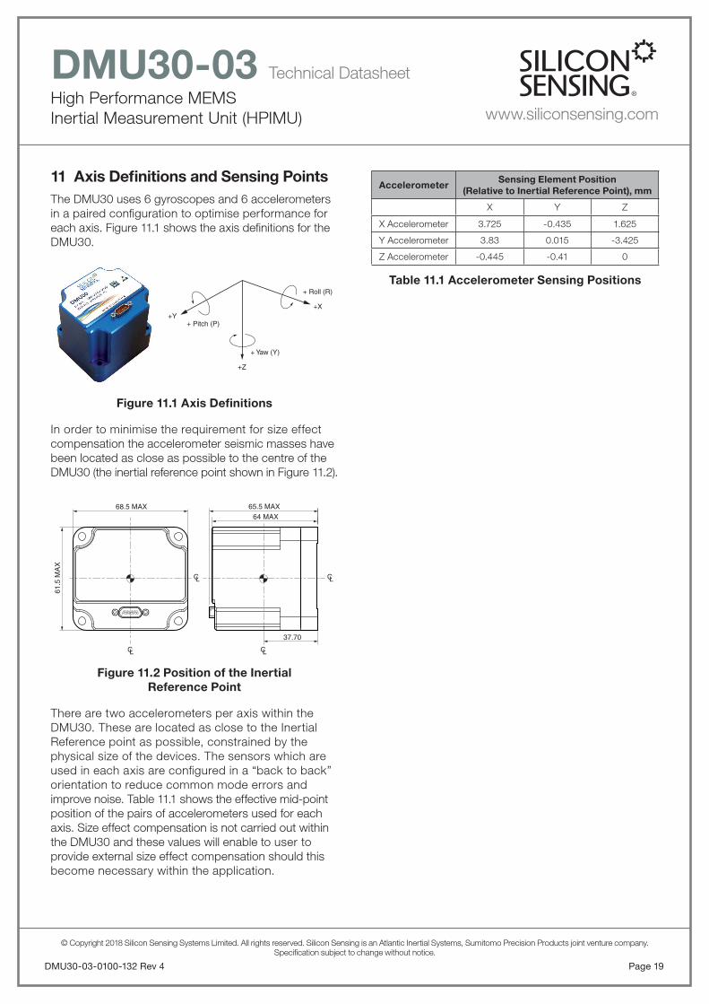
11 Axis Defi nitions and Sensing PointsThe DMU30 uses 6 gyroscopes and 6 accelerometers in a paired confi guration to optimise performance for each axis. Figure 11.1 shows the axis defi nitions for the DMU30.
Figure 11.1 Axis Defi nitions
In order to minimise the requirement for size effect compensation the accelerometer seismic masses have been located as close as possible to the centre of the DMU30 (the inertial reference point shown in Figure 11.2).
Figure 11.2 Position of the InertialReference Point
There are two accelerometers per axis within the DMU30. These are located as close to the Inertial Reference point as possible, constrained by the physical size of the devices. The sensors which are used in each axis are confi gured in a “back to back” orientation to reduce common mode errors and improve noise. Table 11.1 shows the effective mid-point position of the pairs of accelerometers used for each axis. Size effect compensation is not carried out within the DMU30 and these values will enable to user to provide external size effect compensation should this become necessary within the application.
Page 19DMU30-03-0100-132 Rev 4
AccelerometerSensing Element Position
(Relative to Inertial Reference Point), mm
X Y Z
X Accelerometer 3.725 -0.435 1.625
Y Accelerometer 3.83 0.015 -3.425
Z Accelerometer -0.445 -0.41 0
Table 11.1 Accelerometer Sensing Positions
+ Pitch (P)+Y
+ Roll (R)
+X
+ Yaw (Y)
+Z
61.5
MA
X
68.5 MAX64 MAX
65.5 MAX
37.70
CL
CL CL
CL

© Copyright 2018 Silicon Sensing Systems Limited. All rights reserved. Silicon Sensing is an Atlantic Inertial Systems, Sumitomo Precision Products joint venture company.Specifi cation subject to change without notice.
High Performance MEMSInertial Measurement Unit (HPIMU)
DMU30-03 Technical Datasheet
www.siliconsensing.com
DMU30-03-0100-132 Rev 4Page 20
12 DMU30 Construction and Theory of Operation
12.1 IMU Construction
DMU30 is an aluminium alloy assembly comprising base, housing, sensor block, sensor assemblies and IMU electronics.
The base and housing are sealed using a self-forming gasket and secured by four machine screws to provide a waterproof enclosure. A micro-miniature ‘D’ type socket connector located on the top face of the housing provides the electrical interface to the host system. The top face of the housing displays the DMU30 part marking information.
DMU30 is aligned to the host system using two Ø3mm dowels in the host platform which locate with matching dowel holes in the bottom face of the base. The IMU is secured to the host using M5.0 machine screws.
A precision machined aluminium 3-Axis Sensor Block, secured to the DMU30 Base by machine screws provides accurate alignment and support for the DMU30 MEMS inertial sensor assemblies and IMU electronics. Internally generated heat from the sensor assemblies and IMU electronics is absorbed into the sensor block and surrounding housing and conducted to the host via the base and to the ambient atmosphere via convection cooling fi ns in the housing.
The IMU electronics is a triple-stack PCB assembly which is affi xed to the sensor block by six spacers and machine screws to provide stable and precise alignment between the sensor assemblies.
12.2 Sensor Construction and Theory of Operation
Silicon MEMS Inductive Ring Gyroscope
The silicon MEMS ring is 6mm diameter by 100μm thick, fabricated by Silicon Sensing Systems using a DRIE (Deep Reactive Ion Etch) bulk silicon process.The ring is supported in free-space by sixteen pairs of symmetrical legs which isolate the ring from the supporting structure on the outside of the ring.
Figure 12.1 Silicon MEMS Ring
The bulk silicon etch process and unique patented ring design enable close tolerance geometrical properties for precise balance and thermal stability and, unlike other MEMS gyros, there are no small gaps to create problems of interference and stiction. These features contribute signifi cantly to DMU30’s bias and scale factor stability over temperature, and vibration immunity. Another advantage of the design is its inherent immunity to acceleration induced rate error, or ‘g-sensitivity’.
Figure 12.2 MEMS VSG3QMAX Sensor
The ring is essentially divided into 8 sections with two conductive tracks in each section. These tracks enter and exit the ring on the supporting legs. The silicon ring is bonded to a glass pedestal which in turn is bonded to a glass support base. A magnet, with upper and lower poles, is used to create a strong and uniform magnetic fi eld across the silicon ring. The complete assembly is mounted within a hermetic can.
C.G. 18619
Can Lid
Can Base
Upper Pole
Lower PoleC.G. 18620
Support GlassPedestal Glass
Silicon
Magnet

© Copyright 2018 Silicon Sensing Systems Limited. All rights reserved. Silicon Sensing is an Atlantic Inertial Systems, Sumitomo Precision Products joint venture company.Specifi cation subject to change without notice.
High Performance MEMSInertial Measurement Unit (HPIMU)
DMU30-03 Technical Datasheet
www.siliconsensing.com
Page 21DMU30-03-0100-132 Rev 4
Having established the cos2 mode of vibration on the ring, the ring becomes a Coriolis Vibrating Structure Gyroscope. When the gyroscope is rotated about its sense axis the Coriolis force acts tangentially on the ring, causing motions at 45° displaced from the primary mode of vibration. The amount of motion at this point is directly proportional to the rate of turn applied to the gyroscope. One pair of diametrically opposed tracking sections, known as the Secondary Pick-off SP section, is used to sense the level of this vibration. This is used in a secondary rate nulling loop to apply a signal to another pair of secondary sections, known as the Secondary Drive SD. The current applied to the Secondary Drive to null the secondary mode of vibration is a very accurate measure of the applied angular rate. All of these signals occur at the resonant frequency of the ring. The Secondary Drive signal is demodulated to baseband to give a voltage output directly proportional to the applied rate in free space.
Figure 12.4 Secondary Vibration Mode
The closed loop architecture of both the primary and secondary loops results in excellent bias, scale factor and non-linearity control over a wide range of operating environments and life. The dual loop design, introduced into this new Sensor Head design, coupled with improved geometric symmetry results in excellent performance over temperature and life. The discrete electronics employed in DMU30 ensures that performance is not compromised.
C.G 18400
ResultantRadial Motion
Fc = Coriolis Force
Fc
Fc
Fc
Applied Rate
ν
ν ν
ν
The tracks along the top of the ring form two pairs of drive tracks and two pairs of pick-off tracks. Each section has two loops to improve drive and pick-off quality.
One pair of diametrically opposed tracking sections, known as the Primary Drive PD section, is used to excite the cos2 mode of vibration on the ring. This is achieved by passing current through the tracking and, because the tracks are within a magnetic fi eld, causes motion on the ring. Another pair of diametrically opposed tracking sections are known as the Primary Pick-off PP section are used to measure the amplitude and phase of the vibration on the ring. The Primary Pick-off sections are in the segments 90° to those of the Primary Drive sections. The drive amplitude and frequency is controlled by a precision closed loop electronic architecture with the frequency controlled by a Phase Locked Loop (PLL), operating with a Voltage Controlled Oscillator (VCO), and amplitude controlled with an Automatic Gain Control (AGC) system. The primary loop therefore establishes the vibration on the ring and the closed loop electronics is used to track frequency changes and maintain the optimal amplitude of vibration over temperature and life. The loop is designed to operate at about 14kHz.
Figure 12.3 Primary Vibration Mode
C.G 18623
Zero RadialMotion
at thesepoints
Cos2θVibrationMode at14kHz
ν
ν ν
ν

© Copyright 2018 Silicon Sensing Systems Limited. All rights reserved. Silicon Sensing is an Atlantic Inertial Systems, Sumitomo Precision Products joint venture company.Specifi cation subject to change without notice.
High Performance MEMSInertial Measurement Unit (HPIMU)
DMU30-03 Technical Datasheet
www.siliconsensing.com
DMU30-03-0100-132 Rev 4Page 22
Silicon MEMS Capacitive Accelerometer
The accelerometer contains a seismic ‘proof mass’ with multiple fi ngers suspended via a ‘spring’, from a fi xed supporting structure. The supporting structure is anodically bonded to the top and bottom glass substrates and thereby fi xed to the sensor package base.
When the accelerometer is subjected to a linear acceleration along its sensitive axis, the proof mass tends to resist motion due to its own inertia, therefore the mass and its fi ngers become displaced with respect to the interdigitated fi xed electrode fi ngers (which are also fi xed to glass substrates). Air between the fi ngers provides a damping effect. This displacement induces a differential capacitance between the moving and fi xed silicon fi ngers which is proportional to the applied acceleration.
Capacitor plate groups are electrically connected in pairs at the top and bottom of the proof mass. In-phase and out of phase waveforms are applied by the ASIC separately to the ‘left’ and ‘right’ fi nger groups. The demodulated waveforms provide a signal output proportional to linear acceleration.
Figures 12.5(a) and 12.5(b) provide schematics of the accelerometer structure and control loop respectively.
Figure 12.5(a) Schematic of AccelerometerStructure
Fixed Electrode 1 Fixed Electrode 2
C.G. 18613
Sensing axis Fixed support
Proof mass(includes fingers)
Figure 12.5(b) Schematic of AccelerometerControl Loop
C.G. 18540
Electrode 2
88kHz reference
Signal proportional to movement of proof mass
Out of Phase Square Wave at 88kHz on Electrode 2
In Phase Square Wave at 88kHz on Electrode 1
Amplifier
Electrode 1
Sensing axis
Low pass filter
Output signal
Demodulator

© Copyright 2018 Silicon Sensing Systems Limited. All rights reserved. Silicon Sensing is an Atlantic Inertial Systems, Sumitomo Precision Products joint venture company.Specifi cation subject to change without notice.
High Performance MEMSInertial Measurement Unit (HPIMU)
DMU30-03 Technical Datasheet
www.siliconsensing.com
Notes
Page 23DMU30-03-0100-132 Rev 4

© Copyright 2018 Silicon Sensing Systems Limited. All rights reserved. Silicon Sensing is an Atlantic Inertial Systems, Sumitomo Precision Products joint venture company.Specifi cation subject to change without notice.
High Performance MEMSInertial Measurement Unit (HPIMU)
DMU30-03 Technical Datasheet
www.siliconsensing.com
Specifi cation subject to change without notice.
© Copyright 2018Silicon Sensing Systems LimitedAll rights reserved.
Printed in England 12/2018Date 18/12/2018
DMU30-03-0100-132 Rev 4DCR No. 710015616
Silicon Sensing Systems LimitedClittaford Road SouthwayPlymouth DevonPL6 6DE United Kingdom
T: +44 (0)1752 723330F: +44 (0)1752 723331E: [email protected]: siliconsensing.com
Silicon Sensing Systems Japan Limited1-10 Fuso-ChoAmagasakiHyogo 6600891 Japan
T: +81 (0)6 6489 5868F: +81 (0)6 6489 5919E: [email protected]: siliconsensing.com
DMU30-03-0100-132 Rev 4Page 24
Notes