
technical data - Recair Oy · • Air Handling Unit Connection • Heat pump 3 • Air Handling...
31
air conditioning systems technical data Air handling unit connection ERQ-AV1
Transcript of technical data - Recair Oy · • Air Handling Unit Connection • Heat pump 3 • Air Handling...
air conditioning systems
technical data
Air handling unit connection
ERQ-AV1

air conditioning systems
technical data
Air handling unit connection
ERQ-AV1

• Air Handling Unit Connection • Heat pump 1
• Air Handling Unit Connection • ERQ-AV1
TABLE OF CONTENTSERQ-AV1
1 Features . . . . . . . . . . . . . . . . . . . . . . . . . . . . . . . . . . . . . . . . . . . . . . . . . . . . . . . . . . . . . 2
2 Specifications . . . . . . . . . . . . . . . . . . . . . . . . . . . . . . . . . . . . . . . . . . . . . . . . . . . . . . . 3Nominal Capacity and Nominal Input . . . . . . . . . . . . . . . . . . . . . . . . . . . . . . . . 3Technical Specifications . . . . . . . . . . . . . . . . . . . . . . . . . . . . . . . . . . . . . . . . . . . . . 3Electrical Specifications . . . . . . . . . . . . . . . . . . . . . . . . . . . . . . . . . . . . . . . . . . . . . . 4
3 Options . . . . . . . . . . . . . . . . . . . . . . . . . . . . . . . . . . . . . . . . . . . . . . . . . . . . . . . . . . . . . . 5
4 Integrated heating capacity coefficient . . . . . . . . . . . . . . . . . . . . . . . . . . 6
5 Capacity tables . . . . . . . . . . . . . . . . . . . . . . . . . . . . . . . . . . . . . . . . . . . . . . . . . . . . . 7Combination table . . . . . . . . . . . . . . . . . . . . . . . . . . . . . . . . . . . . . . . . . . . . . . . . . . . . 7Cooling capacity tables . . . . . . . . . . . . . . . . . . . . . . . . . . . . . . . . . . . . . . . . . . . . . . 8Heating capacity tables . . . . . . . . . . . . . . . . . . . . . . . . . . . . . . . . . . . . . . . . . . . . . 14Capacity correction factor . . . . . . . . . . . . . . . . . . . . . . . . . . . . . . . . . . . . . . . . . . . 20
6 Dimensional drawing & centre of gravity . . . . . . . . . . . . . . . . . . . . . . . 20
Dimensional drawing . . . . . . . . . . . . . . . . . . . . . . . . . . . . . . . . . . . . . . . . . . . . . . . . 20Centre of gravity . . . . . . . . . . . . . . . . . . . . . . . . . . . . . . . . . . . . . . . . . . . . . . . . . . . . 21
7 Piping diagram. . . . . . . . . . . . . . . . . . . . . . . . . . . . . . . . . . . . . . . . . . . . . . . . . . . . . 21
8 Wiring diagram. . . . . . . . . . . . . . . . . . . . . . . . . . . . . . . . . . . . . . . . . . . . . . . . . . . . . 22Wiring diagram . . . . . . . . . . . . . . . . . . . . . . . . . . . . . . . . . . . . . . . . . . . . . . . . . . . . . . 22External connection diagram . . . . . . . . . . . . . . . . . . . . . . . . . . . . . . . . . . . . . . . . 22
9 Sound data . . . . . . . . . . . . . . . . . . . . . . . . . . . . . . . . . . . . . . . . . . . . . . . . . . . . . . . . . 23Sound pressure spectrum . . . . . . . . . . . . . . . . . . . . . . . . . . . . . . . . . . . . . . . . . . . 23Sound power spectrum . . . . . . . . . . . . . . . . . . . . . . . . . . . . . . . . . . . . . . . . . . . . . 25
10 Installation . . . . . . . . . . . . . . . . . . . . . . . . . . . . . . . . . . . . . . . . . . . . . . . . . . . . . . . . . . 26Service space . . . . . . . . . . . . . . . . . . . . . . . . . . . . . . . . . . . . . . . . . . . . . . . . . . . . . . . 26
11 Operation range . . . . . . . . . . . . . . . . . . . . . . . . . . . . . . . . . . . . . . . . . . . . . . . . . . . 28
• Air Handling Unit Connection • ERQ-AV1
• Air Handling Unit Connection • Heat pump2
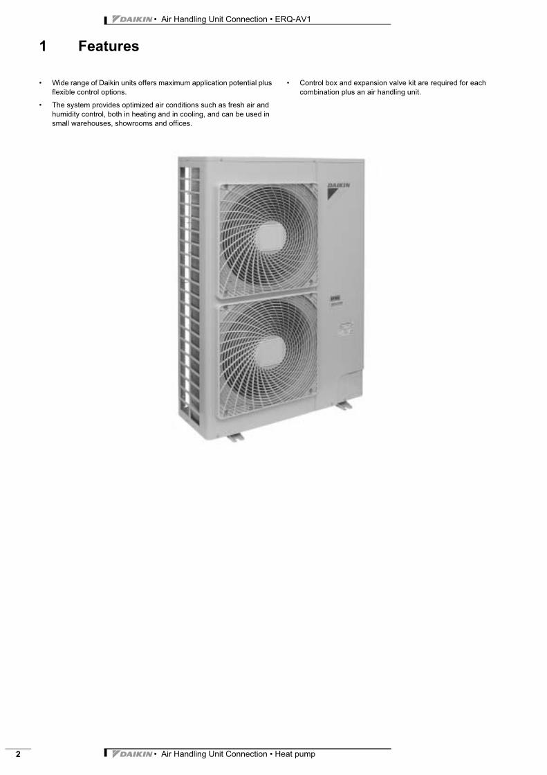
1 Features
Air Handlin ERQ-AV1 Heat pump Heat pump • Wide range of Daikin units offers maximum application potential plus flexible control options.
• The system provides optimized air conditions such as fresh air and humidity control, both in heating and in cooling, and can be used in small warehouses, showrooms and offices.
• Control box and expansion valve kit are required for each combination plus an air handling unit.
• Air Handling Unit Connection • Heat pump 3
• Air Handling Unit Connection • ERQ-AV1
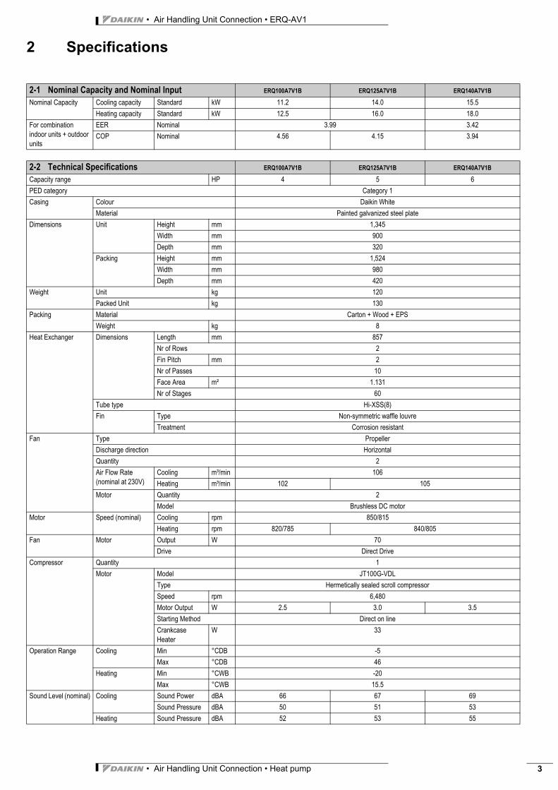
2 Specifications
2-1 Nominal Capacity and Nominal Input ERQ100A7V1B ERQ125A7V1B ERQ140A7V1B
Nominal Capacity Cooling capacity Standard kW 11.2 14.0 15.5Heating capacity Standard kW 12.5 16.0 18.0
For combination indoor units + outdoor units
EER Nominal 3.99 3.42COP Nominal 4.56 4.15 3.94
2-2 Technical Specifications ERQ100A7V1B ERQ125A7V1B ERQ140A7V1B
Capacity range HP 4 5 6PED category Category 1Casing Colour Daikin White
Material Painted galvanized steel plateDimensions Unit Height mm 1,345
Width mm 900Depth mm 320
Packing Height mm 1,524Width mm 980Depth mm 420
Weight Unit kg 120Packed Unit kg 130
Packing Material Carton + Wood + EPSWeight kg 8
Heat Exchanger Dimensions Length mm 857Nr of Rows 2Fin Pitch mm 2Nr of Passes 10Face Area m² 1.131Nr of Stages 60
Tube type Hi-XSS(8)Fin Type Non-symmetric waffle louvre
Treatment Corrosion resistantFan Type Propeller
Discharge direction HorizontalQuantity 2Air Flow Rate (nominal at 230V)
Cooling m³/min 106Heating m³/min 102 105
Motor Quantity 2Model Brushless DC motor
Motor Speed (nominal) Cooling rpm 850/815Heating rpm 820/785 840/805
Fan Motor Output W 70Drive Direct Drive
Compressor Quantity 1Motor Model JT100G-VDL
Type Hermetically sealed scroll compressorSpeed rpm 6,480Motor Output W 2.5 3.0 3.5Starting Method Direct on lineCrankcase Heater
W 33
Operation Range Cooling Min °CDB -5Max °CDB 46
Heating Min °CWB -20Max °CWB 15.5
Sound Level (nominal) Cooling Sound Power dBA 66 67 69Sound Pressure dBA 50 51 53
Heating Sound Pressure dBA 52 53 55
• Air Handling Unit Connection • ERQ-AV1
• Air Handling Unit Connection • Heat pump4
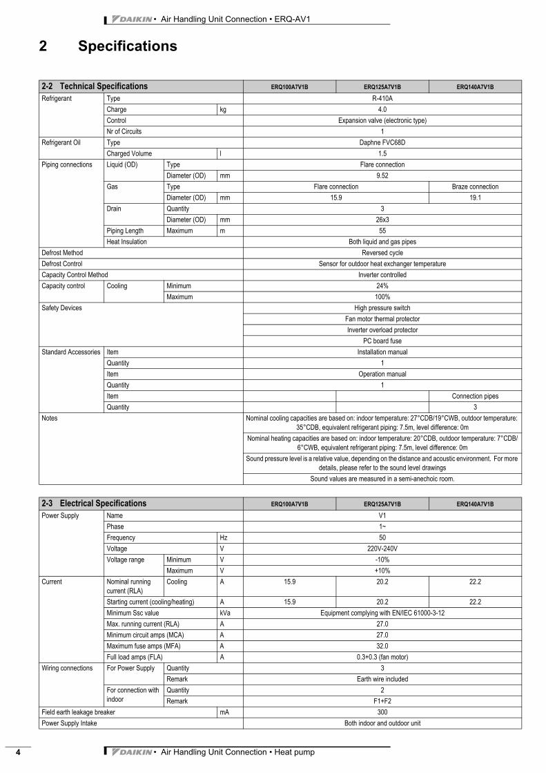
2 Specifications
Refrigerant Type R-410ACharge kg 4.0Control Expansion valve (electronic type)Nr of Circuits 1
Refrigerant Oil Type Daphne FVC68DCharged Volume l 1.5
Piping connections Liquid (OD) Type Flare connectionDiameter (OD) mm 9.52
Gas Type Flare connection Braze connectionDiameter (OD) mm 15.9 19.1
Drain Quantity 3Diameter (OD) mm 26x3
Piping Length Maximum m 55Heat Insulation Both liquid and gas pipes
Defrost Method Reversed cycleDefrost Control Sensor for outdoor heat exchanger temperatureCapacity Control Method Inverter controlledCapacity control Cooling Minimum 24%
Maximum 100%Safety Devices High pressure switch
Fan motor thermal protectorInverter overload protector
PC board fuseStandard Accessories Item Installation manual
Quantity 1Item Operation manualQuantity 1Item Connection pipesQuantity 3
Notes Nominal cooling capacities are based on: indoor temperature: 27°CDB/19°CWB, outdoor temperature: 35°CDB, equivalent refrigerant piping: 7.5m, level difference: 0m
Nominal heating capacities are based on: indoor temperature: 20°CDB, outdoor temperature: 7°CDB/6°CWB, equivalent refrigerant piping: 7.5m, level difference: 0m
Sound pressure level is a relative value, depending on the distance and acoustic environment. For more details, please refer to the sound level drawings
Sound values are measured in a semi-anechoic room.
2-3 Electrical Specifications ERQ100A7V1B ERQ125A7V1B ERQ140A7V1B
Power Supply Name V1Phase 1~Frequency Hz 50Voltage V 220V-240VVoltage range Minimum V -10%
Maximum V +10%Current Nominal running
current (RLA)Cooling A 15.9 20.2 22.2
Starting current (cooling/heating) A 15.9 20.2 22.2Minimum Ssc value kVa Equipment complying with EN/IEC 61000-3-12Max. running current (RLA) A 27.0Minimum circuit amps (MCA) A 27.0Maximum fuse amps (MFA) A 32.0Full load amps (FLA) A 0.3+0.3 (fan motor)
Wiring connections For Power Supply Quantity 3Remark Earth wire included
For connection with indoor
Quantity 2Remark F1+F2
Field earth leakage breaker mA 300Power Supply Intake Both indoor and outdoor unit
2-2 Technical Specifications ERQ100A7V1B ERQ125A7V1B ERQ140A7V1B

• Air Handling Unit Connection • Heat pump 5
• Air Handling Unit Connection • ERQ-AV1
2 Specifications
3 Options
Notes RLA is based on following conditions: indoor temperature: 27°CDB/19°CWB, outdoor temperature: 35°CDB
Voltage range: units are suitable for use on electrical systems where voltage supplied to unit terminal is not below or above listed range limits
Maximum allowable voltage range variation between phases is 2%.Select wire size based on the value of MCA
Instead of fuse, use circuit breaker. MFA is used to select circuit breaker and the ground fault circuit interrupter (earth leakage circuit breaker).
MSC means the maximum current during start up of the compressorEN/IEC 61000-3-12: European/international technical standard setting the limits for harmonic currents produced by equipment connected to public low-voltage system with input current > 16A and <= 75A per
phaseSSC means short-circuit power
2-3 Electrical Specifications ERQ100A7V1B ERQ125A7V1B ERQ140A7V1B
ERQ-AV1
N° Item ERQ100 ERQ125 ERQ140
1 Cool/heat selector KRC19-26A6
2 Fixing box KJB111A
3 Central drain plug KKPJ5F180
Note: all options are kits 4TW32001-4

• Air Handling Unit Connection • ERQ-AV1
• Air Handling Unit Connection • Heat pump6
4 Integrated heating capacity coefficient
3TW30402-1
Integrated heating capacity coefficientThe heating capacity tables do not take account of the reduction in capacity, when frost has accumulated or while the defrosting operation is in progress.The capacity values, which take these factors into account, in other words, the integrated heating capacity values, can be calculated as follows
Formula:Integrated heating capacity = AValue given in table of capacity characteristics = BIntegrating correction factor for frost accumulation (kW) = CA = B x C
Correction factor for finding integrated heating capacity
ERQ-AV1
Inlet port temperature of heat exchanger (°C/RH 85%) -7 -5 -3 0 3 5 7Integrating correction factor for frost accumulation 0,88 0,86 0,8 0,75 0,76 0,82 1,0
Please note that, when there is an accumulation of snow against the outside surface of the outdoor unit heatexchanger, there will always be a temporary redusion in capacity, although this will of course vary in degree inaccordance with a number of other factors, such as the outdoor temperature (°CDB), relative humidity (RH) andthe amount of frosting which occurs.
Note:1. The figure shows that the integrated heating capacity
expresses the integrated capacity for a single cycle (fromdefrost operation to defrost operation) in terms of time.
Defrosting operation Defrosting operation
Time
One cycle
Hea
ting
capa
city
• Air Handling Unit Connection • Heat pump 7
• Air Handling Unit Connection • ERQ-AV1
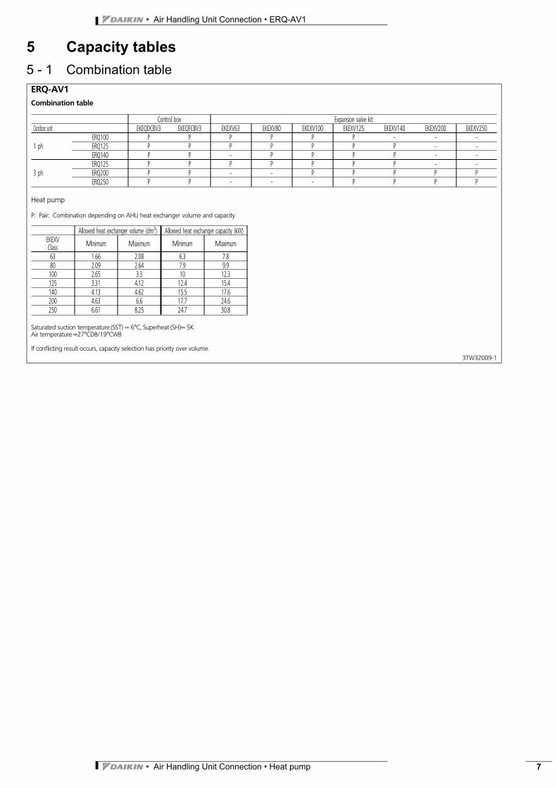
5 Capacity tables5 - 1 Combination tableERQ-AV1Combination table
Control box Expansion valve kitOutdoor unit EKEQDCBV3 EKEQFCBV3 EKEXV63 EKEXV80 EKEXV100 EKEXV125 EKEXV140 EKEXV200 EKEXV250
1 phERQ100 P P P P P P - - -ERQ125 P P P P P P P - -ERQ140 P P - P P P P - -
3 phERQ125 P P P P P P P - -ERQ200 P P - - P P P P PERQ250 P P - - - P P P P
Heat pump
P: Pair: Combination depending on AHU heat exchanger volume and capacity
Allowed heat exchanger volume (dm ) Allowed heat exchanger capacity (kW)EKEXVClass Minimum Maximum Minimum Maximum
63 1.66 2.08 6.3 7.880 2.09 2.64 7.9 9.9100 2.65 3.3 10 12.3125 3.31 4.12 12.4 15.4140 4.13 4.62 15.5 17.6200 4.63 6.6 17.7 24.6250 6.61 8.25 24.7 30.8
Saturated suction temperature (SST) = 6°C, Superheat (SH = 5KAir temperature =27°CDB/19°CWB
If conflicting result occurs, capacity selection has priority over volume.3TW32009-1
)
3
• Air Handling Unit Connection • ERQ-AV1
• Air Handling Unit Connection • Heat pump8
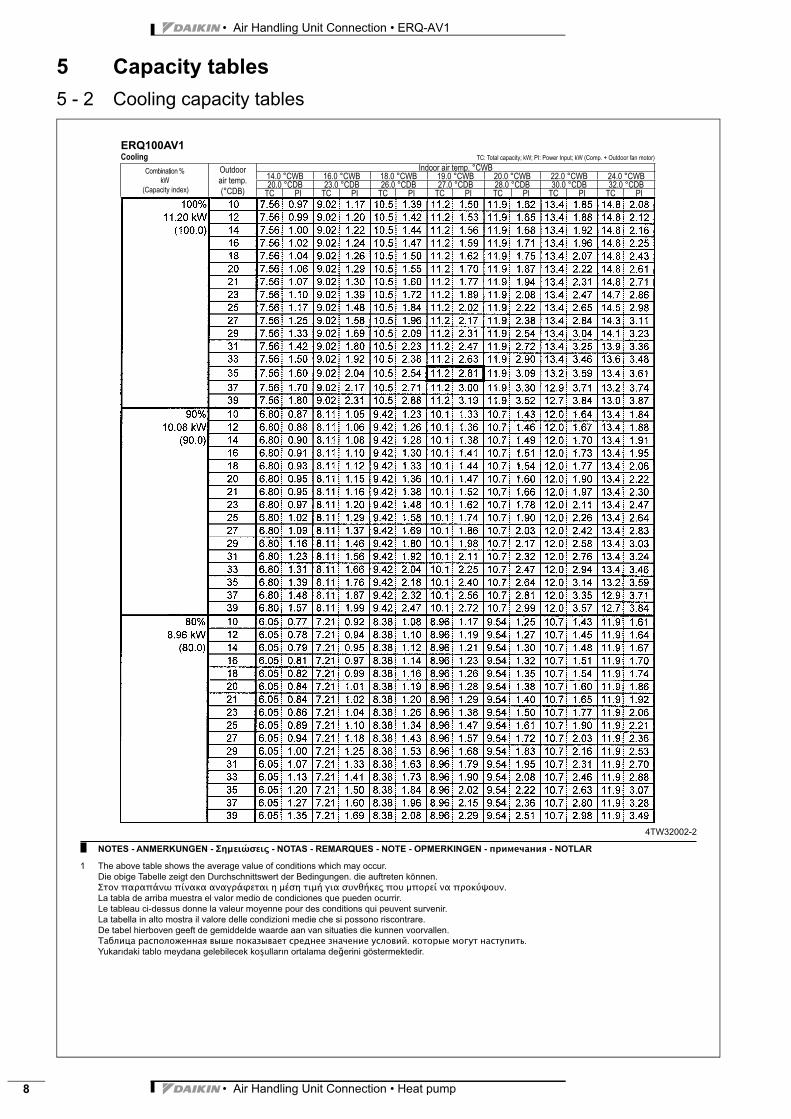
5 Capacity tables5 - 2 Cooling capacity tables
ERQ100AV1
Cooling TC: Total capacity; kW; PI: Power Input; kW (Comp. + Outdoor fan motor)
Combination %
kW
(Capacity index)
Outdoor
air temp.
(°CDB)
Indoor air temp. °CWB
14.0 °CWB 16.0 °CWB 18.0 °CWB 19.0 °CWB 20.0 °CWB 22.0 °CWB 24.0 °CWB
20.0 °CDB 23.0 °CDB 26.0 °CDB 27.0 °CDB 28.0 °CDB 30.0 °CDB 32.0 °CDB
TC PI TC PI TC PI TC PI TC PI TC PI TC PI
4TW32002-2
NOTES - ANMERKUNGEN - - NOTAS - REMARQUES - NOTE - OPMERKINGEN - - NOTLAR
1 The above table shows the average value of conditions which may occur.
Die obige Tabelle zeigt den Durchschnittswert der Bedingungen. die auftreten können.
.
La tabla de arriba muestra el valor medio de condiciones que pueden ocurrir.
Le tableau ci-dessus donne la valeur moyenne pour des conditions qui peuvent survenir.
La tabella in alto mostra il valore delle condizioni medie che si possono riscontrare.
De tabel hierboven geeft de gemiddelde waarde aan van situaties die kunnen voorvallen.
. .
erini göstermektedir.
• Air Handling Unit Connection • Heat pump 9
• Air Handling Unit Connection • ERQ-AV1
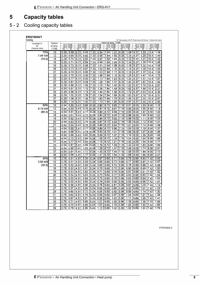
5 Capacity tables5 - 2 Cooling capacity tables
ERQ100AV1
Cooling TC: Total capacity; kW; PI: Power Input; kW (Comp. + Outdoor fan motor)
Combination %
kW
(Capacity index)
Outdoor
air temp.
(°CDB)
Indoor air temp. °CWB
14.0 °CWB 16.0 °CWB 18.0 °CWB 19.0 °CWB 20.0 °CWB 22.0 °CWB 24.0 °CWB
20.0 °CDB 23.0 °CDB 26.0 °CDB 27.0 °CDB 28.0 °CDB 30.0 °CDB 32.0 °CDB
TC PI TC PI TC PI TC PI TC PI TC PI TC PI
4TW32002-2
• Air Handling Unit Connection • ERQ-AV1
• Air Handling Unit Connection • Heat pump10
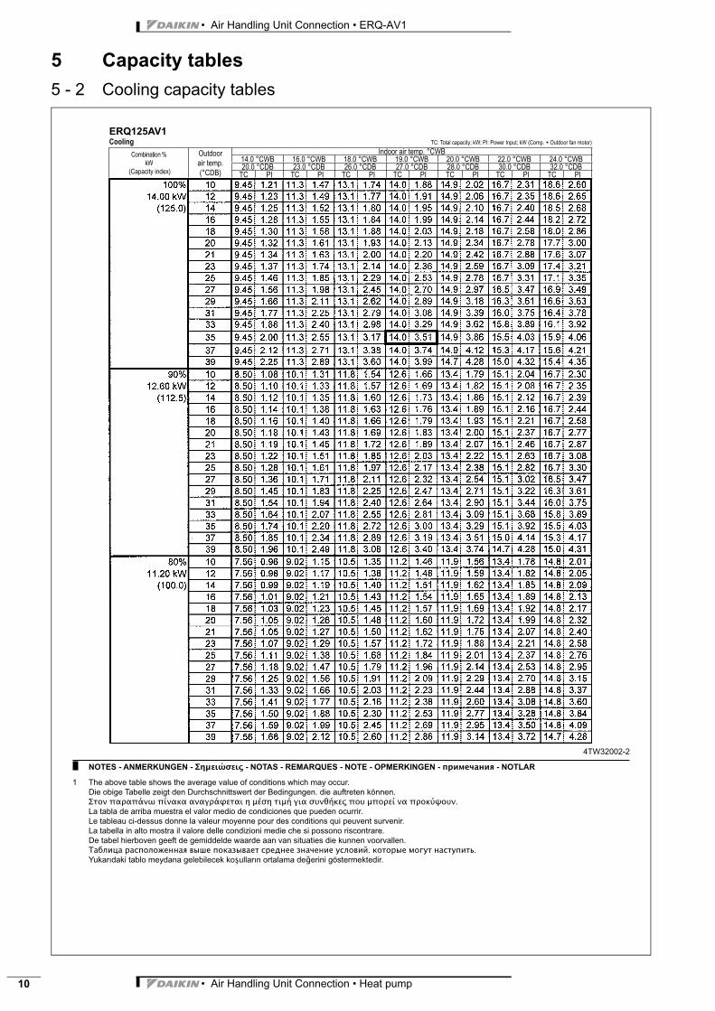
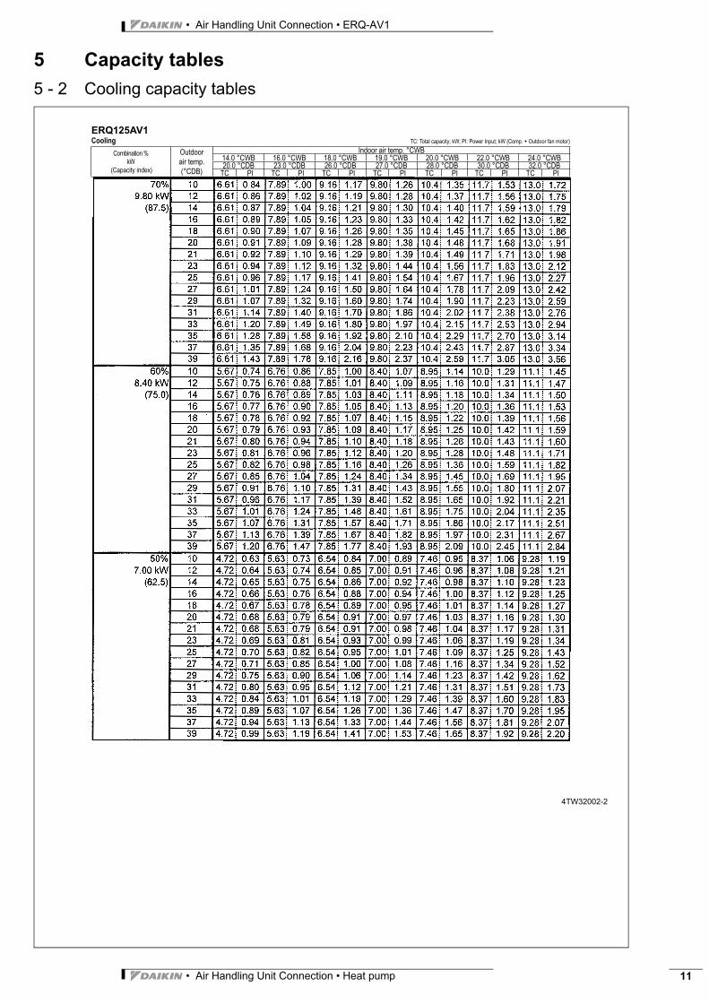
5 Capacity tables5 - 2 Cooling capacity tables
ERQ125AV1
Cooling TC: Total capacity; kW; PI: Power Input; kW (Comp. + Outdoor fan motor)
Combination %
kW
(Capacity index)
Outdoor
air temp.
(°CDB)
Indoor air temp. °CWB
14.0 °CWB 16.0 °CWB 18.0 °CWB 19.0 °CWB 20.0 °CWB 22.0 °CWB 24.0 °CWB
20.0 °CDB 23.0 °CDB 26.0 °CDB 27.0 °CDB 28.0 °CDB 30.0 °CDB 32.0 °CDB
TC PI TC PI TC PI TC PI TC PI TC PI TC PI
4TW32002-2
NOTES - ANMERKUNGEN - - NOTAS - REMARQUES - NOTE - OPMERKINGEN - - NOTLAR
1 The above table shows the average value of conditions which may occur.
Die obige Tabelle zeigt den Durchschnittswert der Bedingungen. die auftreten können.
.
La tabla de arriba muestra el valor medio de condiciones que pueden ocurrir.
Le tableau ci-dessus donne la valeur moyenne pour des conditions qui peuvent survenir.
La tabella in alto mostra il valore delle condizioni medie che si possono riscontrare.
De tabel hierboven geeft de gemiddelde waarde aan van situaties die kunnen voorvallen.
. .
erini göstermektedir.
• Air Handling Unit Connection • Heat pump 11
• Air Handling Unit Connection • ERQ-AV1
5 Capacity tables5 - 2 Cooling capacity tables
ERQ125AV1
Cooling TC: Total capacity; kW; PI: Power Input; kW (Comp. + Outdoor fan motor)
Combination %
kW
(Capacity index)
Outdoor
air temp.
(°CDB)
Indoor air temp. °CWB
14.0 °CWB 16.0 °CWB 18.0 °CWB 19.0 °CWB 20.0 °CWB 22.0 °CWB 24.0 °CWB
20.0 °CDB 23.0 °CDB 26.0 °CDB 27.0 °CDB 28.0 °CDB 30.0 °CDB 32.0 °CDB
TC PI TC PI TC PI TC PI TC PI TC PI TC PI
4TW32002-2
• Air Handling Unit Connection • ERQ-AV1
• Air Handling Unit Connection • Heat pump12
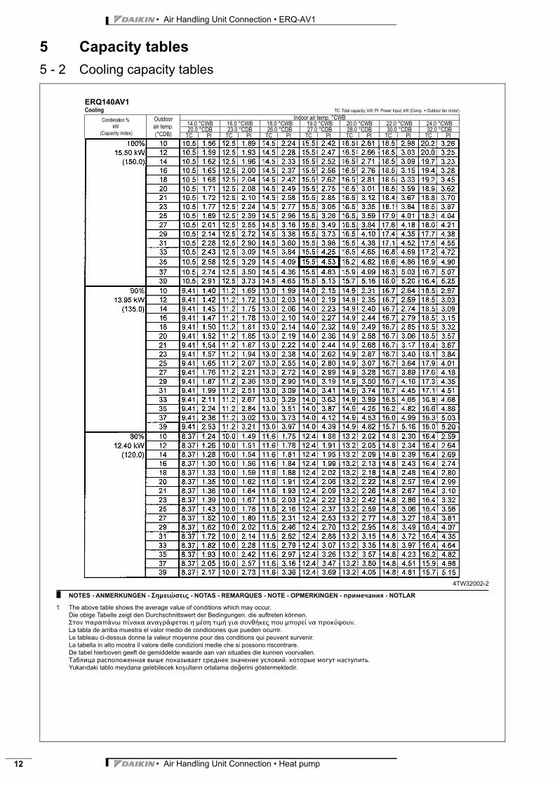
5 Capacity tables5 - 2 Cooling capacity tables
ERQ140AV1
Cooling TC: Total capacity; kW; PI: Power Input; kW (Comp. + Outdoor fan motor)
Combination %
kW
(Capacity index)
Outdoor
air temp.
(°CDB)
Indoor air temp. °CWB
14.0 °CWB 16.0 °CWB 18.0 °CWB 19.0 °CWB 20.0 °CWB 22.0 °CWB 24.0 °CWB
20.0 °CDB 23.0 °CDB 26.0 °CDB 27.0 °CDB 28.0 °CDB 30.0 °CDB 32.0 °CDB
TC PI TC PI TC PI TC PI TC PI TC PI TC PI
4TW32002-2
NOTES - ANMERKUNGEN - - NOTAS - REMARQUES - NOTE - OPMERKINGEN - - NOTLAR
1 The above table shows the average value of conditions which may occur.
Die obige Tabelle zeigt den Durchschnittswert der Bedingungen. die auftreten können.
.
La tabla de arriba muestra el valor medio de condiciones que pueden ocurrir.
Le tableau ci-dessus donne la valeur moyenne pour des conditions qui peuvent survenir.
La tabella in alto mostra il valore delle condizioni medie che si possono riscontrare.
De tabel hierboven geeft de gemiddelde waarde aan van situaties die kunnen voorvallen.
. .
erini göstermektedir.

• Air Handling Unit Connection • Heat pump 13
• Air Handling Unit Connection • ERQ-AV1
5 Capacity tables5 - 2 Cooling capacity tables
ERQ140AV1
Cooling TC: Total capacity; kW; PI: Power Input; kW (Comp. + Outdoor fan motor)
Combination %
kW
(Capacity index)
Outdoor
air temp.
(°CDB)
Indoor air temp. °CWB
14.0 °CWB 16.0 °CWB 18.0 °CWB 19.0 °CWB 20.0 °CWB 22.0 °CWB 24.0 °CWB
20.0 °CDB 23.0 °CDB 26.0 °CDB 27.0 °CDB 28.0 °CDB 30.0 °CDB 32.0 °CDB
TC PI TC PI TC PI TC PI TC PI TC PI TC PI
4TW32002-2
• Air Handling Unit Connection • ERQ-AV1
• Air Handling Unit Connection • Heat pump14
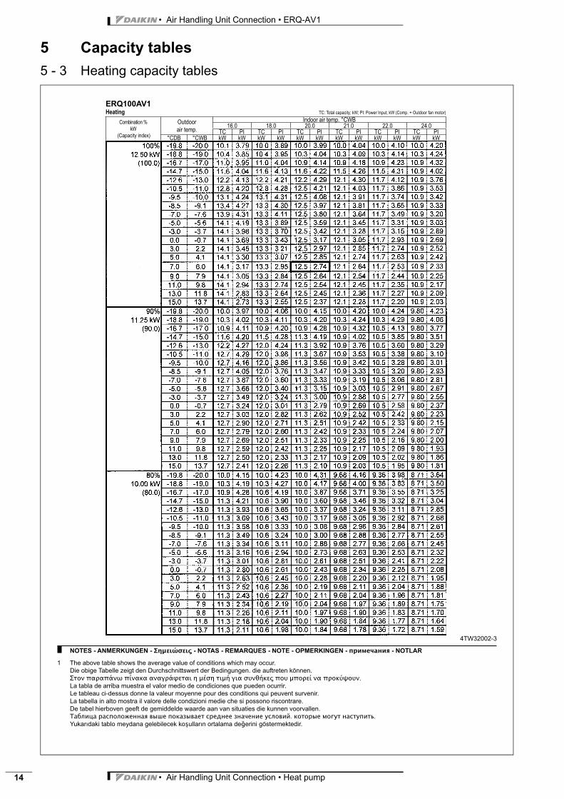
5 Capacity tables5 - 3 Heating capacity tables
ERQ100AV1
Heating TC: Total capacity; kW; PI: Power Input; kW (Comp. + Outdoor fan motor)
Combination %
kW
(Capacity index)
Outdoor
air temp.
Indoor air temp. °CWB
16.0 18.0 20.0 21.0 22.0 24.0
TC PI TC PI TC PI TC PI TC PI TC PI
°CDB °CWB kW kW kW kW kW kW kW kW kW kW kW kW
4TW32002-3
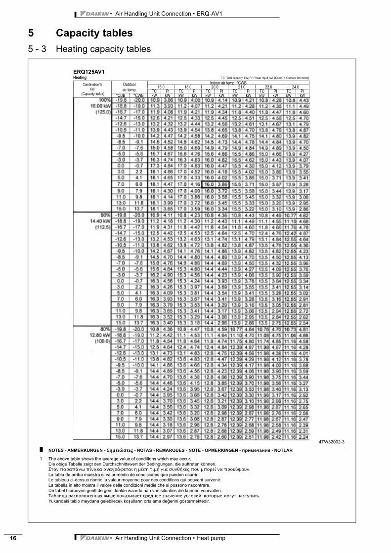
NOTES - ANMERKUNGEN - - NOTAS - REMARQUES - NOTE - OPMERKINGEN - - NOTLAR
1 The above table shows the average value of conditions which may occur.
Die obige Tabelle zeigt den Durchschnittswert der Bedingungen. die auftreten können.
.
La tabla de arriba muestra el valor medio de condiciones que pueden ocurrir.
Le tableau ci-dessus donne la valeur moyenne pour des conditions qui peuvent survenir.
La tabella in alto mostra il valore delle condizioni medie che si possono riscontrare.
De tabel hierboven geeft de gemiddelde waarde aan van situaties die kunnen voorvallen.
. .
erini göstermektedir.
• Air Handling Unit Connection • Heat pump 15
• Air Handling Unit Connection • ERQ-AV1
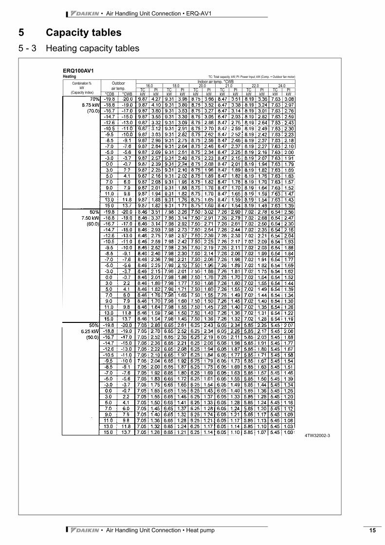
5 Capacity tables5 - 3 Heating capacity tables
ERQ100AV1
Heating TC: Total capacity; kW; PI: Power Input; kW (Comp. + Outdoor fan motor)
Combination %
kW
(Capacity index)
Outdoor
air temp.
Indoor air temp. °CWB
16.0 18.0 20.0 21.0 22.0 24.0
TC PI TC PI TC PI TC PI TC PI TC PI
°CDB °CWB kW kW kW kW kW kW kW kW kW kW kW kW
4TW32002-3
• Air Handling Unit Connection • ERQ-AV1
• Air Handling Unit Connection • Heat pump16
5 Capacity tables5 - 3 Heating capacity tables
ERQ125AV1
Heating TC: Total capacity; kW; PI: Power Input; kW (Comp. + Outdoor fan motor)
Combination %
kW
(Capacity index)
Outdoor
air temp.
Indoor air temp. °CWB
16.0 18.0 20.0 21.0 22.0 24.0
TC PI TC PI TC PI TC PI TC PI TC PI
°CDB °CWB kW kW kW kW kW kW kW kW kW kW kW kW
4TW32002-3
NOTES - ANMERKUNGEN - - NOTAS - REMARQUES - NOTE - OPMERKINGEN - - NOTLAR
1 The above table shows the average value of conditions which may occur.
Die obige Tabelle zeigt den Durchschnittswert der Bedingungen. die auftreten können.
.
La tabla de arriba muestra el valor medio de condiciones que pueden ocurrir.
Le tableau ci-dessus donne la valeur moyenne pour des conditions qui peuvent survenir.
La tabella in alto mostra il valore delle condizioni medie che si possono riscontrare.
De tabel hierboven geeft de gemiddelde waarde aan van situaties die kunnen voorvallen.
. .
erini göstermektedir.

• Air Handling Unit Connection • Heat pump 17
• Air Handling Unit Connection • ERQ-AV1
5 Capacity tables5 - 3 Heating capacity tables
ERQ125AV1
Heating TC: Total capacity; kW; PI: Power Input; kW (Comp. + Outdoor fan motor)
Combination %
kW
(Capacity index)
Outdoor
air temp.
Indoor air temp. °CWB
16.0 18.0 20.0 21.0 22.0 24.0
TC PI TC PI TC PI TC PI TC PI TC PI
°CDB °CWB kW kW kW kW kW kW kW kW kW kW kW kW
4TW32002-3
• Air Handling Unit Connection • ERQ-AV1
• Air Handling Unit Connection • Heat pump18
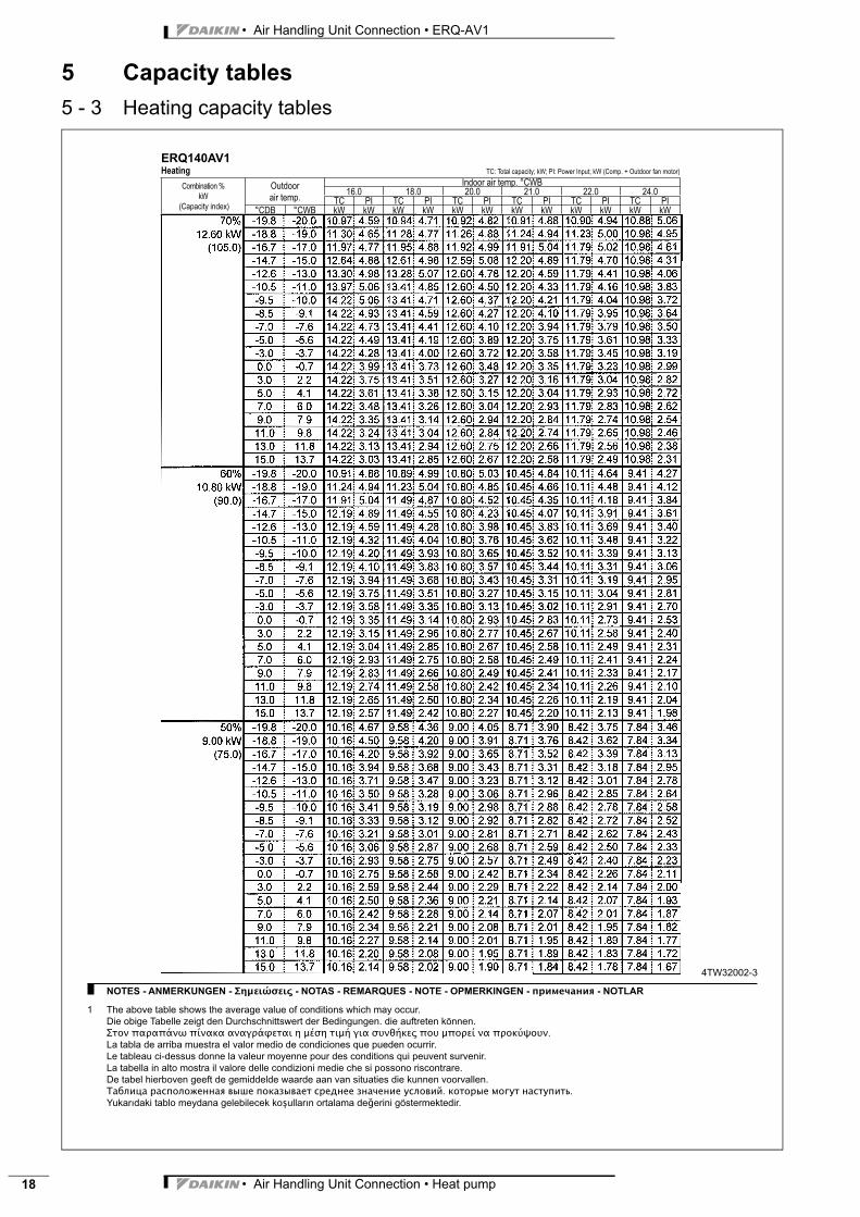
5 Capacity tables5 - 3 Heating capacity tables
ERQ140AV1
Heating TC: Total capacity; kW; PI: Power Input; kW (Comp. + Outdoor fan motor)
Combination %
kW
(Capacity index)
Outdoor
air temp.
Indoor air temp. °CWB
16.0 18.0 20.0 21.0 22.0 24.0
TC PI TC PI TC PI TC PI TC PI TC PI
°CDB °CWB kW kW kW kW kW kW kW kW kW kW kW kW
4TW32002-3
NOTES - ANMERKUNGEN - - NOTAS - REMARQUES - NOTE - OPMERKINGEN - - NOTLAR
1 The above table shows the average value of conditions which may occur.
Die obige Tabelle zeigt den Durchschnittswert der Bedingungen. die auftreten können.
.
La tabla de arriba muestra el valor medio de condiciones que pueden ocurrir.
Le tableau ci-dessus donne la valeur moyenne pour des conditions qui peuvent survenir.
La tabella in alto mostra il valore delle condizioni medie che si possono riscontrare.
De tabel hierboven geeft de gemiddelde waarde aan van situaties die kunnen voorvallen.
. .
erini göstermektedir.
• Air Handling Unit Connection • Heat pump 19
• Air Handling Unit Connection • ERQ-AV1
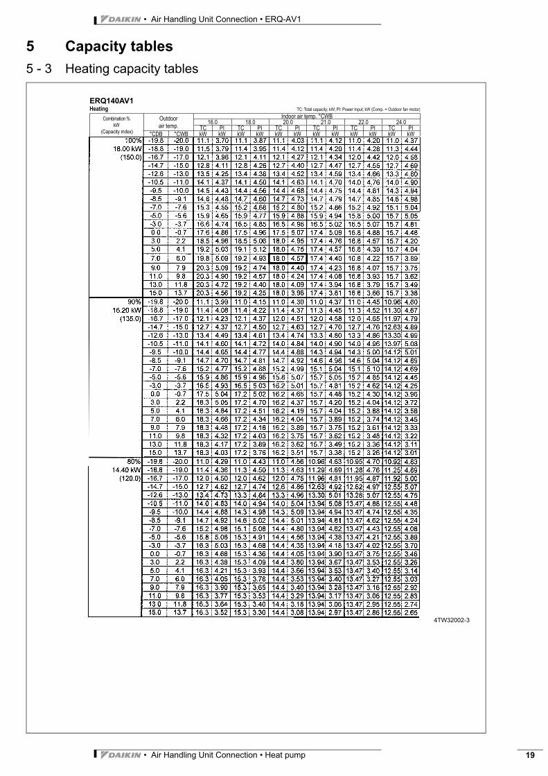
5 Capacity tables5 - 3 Heating capacity tables
ERQ140AV1
Heating TC: Total capacity; kW; PI: Power Input; kW (Comp. + Outdoor fan motor)
Combination %
kW
(Capacity index)
Outdoor
air temp.
Indoor air temp. °CWB
16.0 18.0 20.0 21.0 22.0 24.0
TC PI TC PI TC PI TC PI TC PI TC PI
°CDB °CWB kW kW kW kW kW kW kW kW kW kW kW kW
4TW32002-3
• Air Handling Unit Connection • ERQ-AV1
• Air Handling Unit Connection • Heat pump20
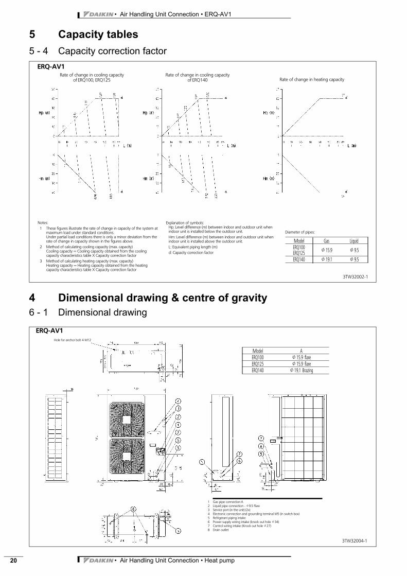
5 Capacity tables5 - 4 Capacity correction factor
4 Dimensional drawing & centre of gravity6 - 1 Dimensional drawing
3TW32002-1
ERQ-AV1Rate of change in cooling capacity
of ERQ140Rate of change in cooling capacity
of ERQ100, ERQ125
Notes:1 These figures illustrate the rate of change in capacity of the system at
maximum load under standard conditions.Under partial load conditions there is only a minor deviation from therate of change in capacity shown in the figures above.
2 Method of calculating cooling capacity (max. capacity)Cooling capacity = Cooling capacity obtained from the coolingcapacity characteristics table X Capacity correction factor
3 Method of calculating heating capacity (max. capacity)Heating capacity = Heating capacity obtained from the heatingcapacity characteristics table X Capacity correction factor
Explanation of symbols:Hp: Level difference (m) between indoor and outdoor unit whenindoor unit is installed below the outdoor unit.Hm: Level difference (m) between indoor and outdoor unit whenindoor unit is installed above the outdoor unit.L: Equivalent piping length (m)d: Capacity correction factor
Diameter of pipes:
Model Gas LiquidERQ100ERQ125 J15.9 J9.5
ERQ140 J19.1 J9.5
Rate of change in heating capacity
3TW32004-1
1 Gas pipe connection A2 Liquid pipe connection - J9.5 flare3 Service port (in the unit) (2x)4 Electronic connection and grounding terminal M5 (in switch box)5 Refrigerant piping intake6 Power supply wiring intake (knock out hole J34)7 Control wiring intake (Knock out hole J27)8 Drain outlet
Hole for anchor bolt 4-M12
ERQ-AV1
Model AERQ100 J15.9 flareERQ125 J15.9 flareERQ140 J19.1 Brazing
• Air Handling Unit Connection • Heat pump 21
• Air Handling Unit Connection • ERQ-AV1
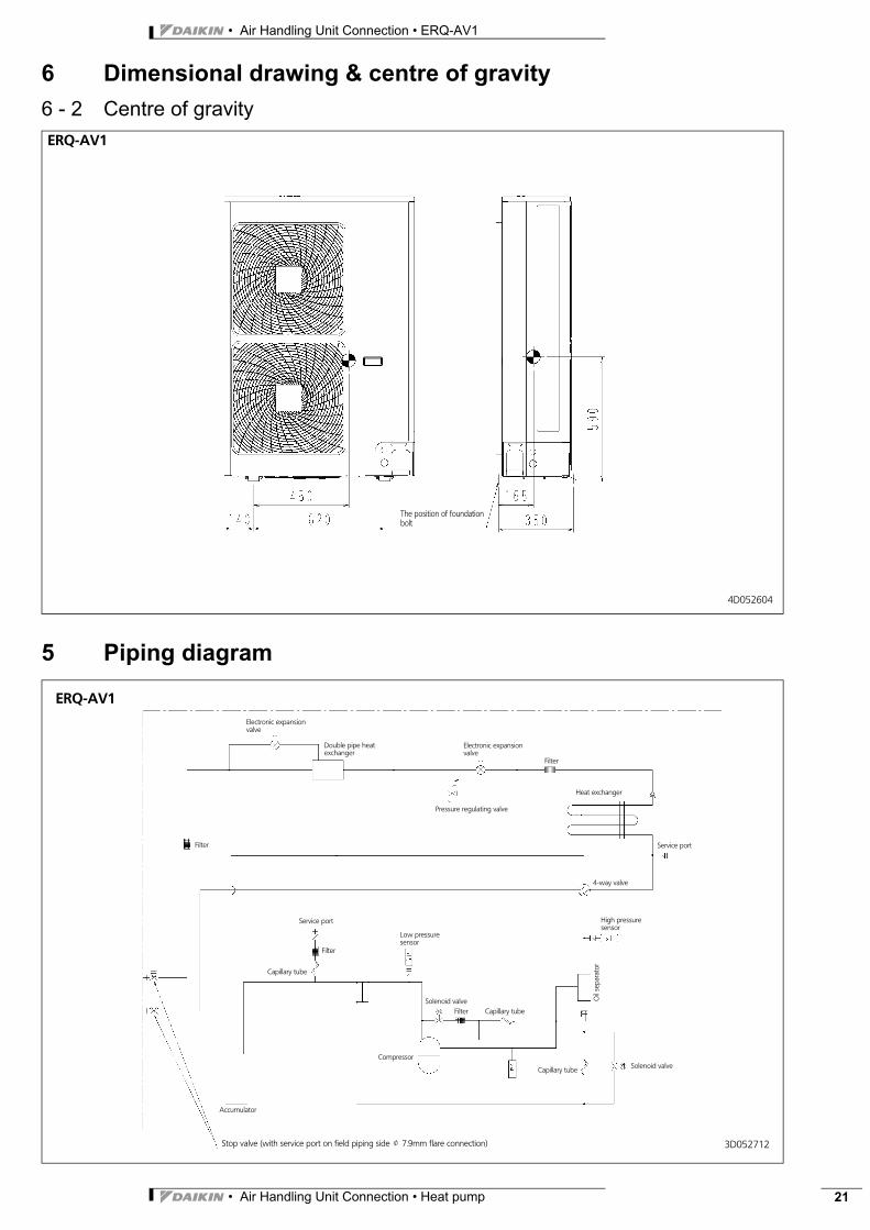
6 Dimensional drawing & centre of gravity6 - 2 Centre of gravity
5 Piping diagram
4D052604
ERQ-AV1
The position of foundationbolt
3D052712
ERQ-AV1
Heat exchanger
Compressor
High pressuresensor
Filter
Filter
Filter
Pressure regulating valve
4-way valve
Solenoid valve
Electronic expansionvalve
Electronic expansionvalve
Low pressuresensor
Capillary tube
Service port
Double pipe heatexchanger
Oil
sepa
rato
r
Stop valve (with service port on field piping side J 7.9mm flare connection)
Solenoid valve
Filter
Service port
Capillary tube
Capillary tube
Accumulator
• Air Handling Unit Connection • ERQ-AV1
• Air Handling Unit Connection • Heat pump22
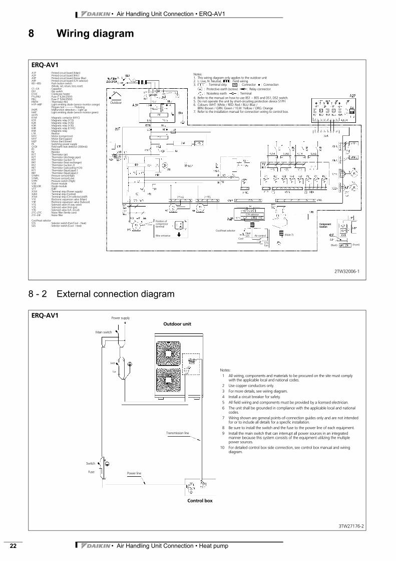
8 Wiring diagram
8 - 2 External connection diagram
2TW32006-1
ERQ-AV1A1P : Printed circuit board (Main)A2P : Printed circuit board (INV.)A3P : Printed circuit board (Noise filter)A4P : Printed circuit board (C/H selector)BS1∼BS5 : Push button switch
(Mode, set, return, test, reset)C1∼C4 : CapacitorDS1 : Dip switchE1HC : Crankcase heaterF1U,F4U : Fuse (T 6,3A/250V)F6U : Fuse (T 5,0A/250V)FINTH : Thermistor (fin)H1P∼H8P : Light emitting diode (service monitor orange)
: Prepare test ----------- Flickering[H2P] : Malfunction detection--- Light upHAP : Light emitting diode (service monitor green)(A1P)K1M : Magnetic contactor (M1C)K1R : Magnetic relay (Y1S)K2R : Magnetic relay (Y2S)K3R : Magnetic relay (Y3S)K4R : Magnetic relay (E1HC)K5R : Magnetic relayL1R : ReactorM1C : Motor (compressor)M1F : Motor (fan) (upper)M2F : Motor (fan) (lower)PS : Switching power supplyQ1DI : Field earth leak detector (300mA)R1 : ResistorR2 : ResistorR1T : Thermistor (air)R2T : Thermistor (discharge pipe)R3T : Thermistor (suction 1)R4T : Thermistor (heat exchanger)R5T : Thermistor (suction 2)R6T : Thermistor (subcooling H.EX)R7T : Thermistor (liquid pipe) 1R8T : Thermistor (liquid pipe) 2S1NPH : Pressure sensor(High)S1NPL : Pressure sensor(Low)S1PH : Pressure switch (High)V1R : Power moduleV2R,V3R : Diode moduleV1T : IGBTX1M : Terminal strip (Power supply)X2M : Terminal strip (Control)X1M : Terminal strip (C/H selector) (A4P)Y1E : Electronic expansion valve (Main)Y3E : Electronic expansion valve (Subcool)Y1S : Solenoid valve (4 way valve)Y2S : Solenoid valve (Hot gas)Y3S : Solenoid valve (U/L circuit)Z1C∼Z7C : Noise filter (ferrite core)Z1F∼Z4F : Noise filter
Cool/heat selectorS1S : Selector switch (Fan/Cool - Heat)S2S : Selector switch (Cool - Heat)
Notes:1. This wiring diagram only applies to the outdoor unit2. L: Live, N: Neutral, : Field wiring3. : Terminal strip : Connector : Connection
: Protective earth (screw) : Relay connector: Noiseless earth : Terminal
4. Refer to the manual on how to use BS1 ∼ BS5 and DS1, DS2 switch.5. Do not operate the unit by short-circuiting protection device S1PH6. Colours: WHT: White / RED: Red / BLU: Blue /
BRN: Brown / GRN: Green / YLW: Yellow / ORG: Orange7. Refer to the installation manual for connection wiring to control box.
Position ofcompressorterminal
Wire entrance
Outdoor
Componentlocation
(Back) (Front)
(Note 7)
C/H selector
Cool/heat selector
Cool
HeatS2S Air control
S1SFan
3TW27176-2
ERQ-AV1
Notes:1 All wiring, components and materials to be procured on the site must comply
with the applicable local and national codes.2 Use copper conductors only.3 For more details, see wiring diagram.4 Install a circuit breaker for safety.5 All field wiring and components must be provided by a licensed electrician.6 The unit shall be grounded in compliance with the applicable local and national
codes.7 Wiring shown are general points-of-connection guides only and are not intended
for or to include all details for a specific installation.8 Be sure to install the switch and the fuse to the power line of each equipment.9 Install the main switch that can interrupt all power sources in an integrated
manner because this system consists of the equipment utilizing the multiplepower sources.
10 For detailed control box side connection, see control box manual and wiringdiagram.
Power supply
Outdoor unit
Main switch
Switch
Fuse
Switch
Fuse
Transmission line
Control box
Power line
• Air Handling Unit Connection • Heat pump 23
• Air Handling Unit Connection • ERQ-AV1
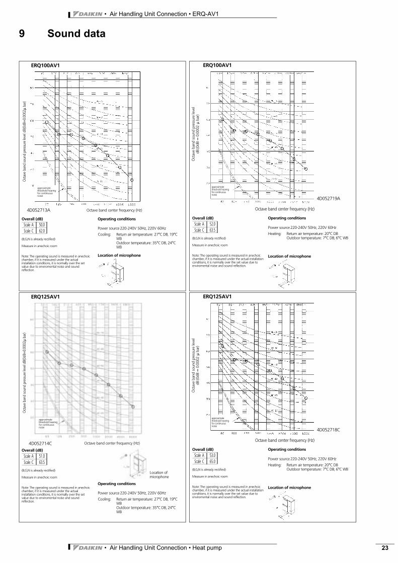
9 Sound data
4D052713A
Oct
ave
band
soun
dpr
essu
rele
veld
B(0d
B=0.
0002
μba
r)
Octave band center frequency (Hz)
ERQ100AV1
Overall (dB)
Scale A 50.0Scale C 62.0
(B,G,N is already rectified)
Measure in anechoic room
Note: The operating sound is measured in anechoicchamber, if it is measured under the actualinstallation conditions, it is normally over the setvalue due to enviromental noise and soundreflection.
Location of microphone
approximatethreshold hearingfor continuousnoise
Operating conditions
Power source 220-240V 50Hz, 220V 60Hz
Return air temperature: 27°C DB, 19°CWBOutdoor temperature: 35°C DB, 24°CWB
Cooling:
4D052719AO
ctav
eba
ndso
und
pres
sure
leve
ldB
:(0dB
=0.
0002
μba
r)
Octave band center frequency (Hz)
ERQ100AV1
approximatethreshold hearingfor continuousnoise
Power source 220-240V 50Hz, 220V 60Hz
Heating: Return air temperature: 20°C DBOutdoor temperature: 7°C DB, 6°C WB
Location of microphone
Overall (dB)
Scale A 52.0Scale C 63.5
(B,G,N is already rectified)
Measure in anechoic room
Note: The operating sound is measured in anechoicchamber, if it is measured under the actual installationconditions, it is normally over the set value due toenviromental noise and sound reflection.
Operating conditions
Oct
ave
band
soun
dpr
essu
rele
veld
B(0d
B=0.
0002
μba
r)
ERQ125AV1
Location ofmicrophone
4D052714COverall (dB)
Scale A 51.0Scale C 63.5
(B,G,N is already rectified)
Measure in anechoic room
Note: The operating sound is measured in anechoicchamber, if it is measured under the actualinstallation conditions, it is normally over the setvalue due to enviromental noise and soundreflection.
Octave band center frequency (Hz)
approximatethreshold hearingfor continuousnoise
Operating conditions
Power source 220-240V 50Hz, 220V 60Hz
Return air temperature: 27°C DB, 19°CWBOutdoor temperature: 35°C DB, 24°CWB
Cooling:
4D052718C
Oct
ave
band
soun
dpr
essu
rele
vel
dB:(0
dB=
0.00
02μ
bar)
Octave band center frequency (Hz)
ERQ125AV1
approximatethreshold hearingfor continuousnoise
Power source 220-240V 50Hz, 220V 60Hz
Heating: Return air temperature: 20°C DBOutdoor temperature: 7°C DB, 6°C WB
Location of microphone
Overall (dB)
Scale A 53.0Scale C 65.0
(B,G,N is already rectified)
Measure in anechoic room
Note: The operating sound is measured in anechoicchamber, if it is measured under the actual installationconditions, it is normally over the set value due toenviromental noise and sound reflection.
Operating conditions
• Air Handling Unit Connection • ERQ-AV1
• Air Handling Unit Connection • Heat pump24
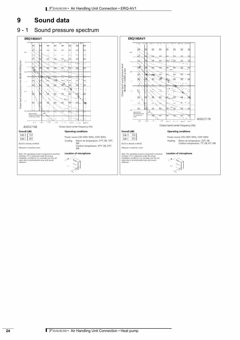
9 Sound data9 - 1 Sound pressure spectrum
4D052716B
Oct
ave
band
soun
dpr
essu
rele
veld
B(0d
B=0.
0002
μba
r)
Octave band center frequency (Hz)
ERQ140AV1
Overall (dB)
Scale A 53.0Scale C 64.5
(B,G,N is already rectified)
Measure in anechoic room
Note: The operating sound is measured in anechoicchamber, if it is measured under the actualinstallation conditions, it is normally over the setvalue due to enviromental noise and soundreflection.
Location of microphone
approximatethreshold hearing forcontinuous noise
Operating conditions
Power source 220-240V 50Hz, 220V 60Hz
Return air temperature: 27°C DB, 19°CWBOutdoor temperature: 35°C DB, 24°CWB
Cooling:
4D052717BO
ctav
eba
ndso
und
pres
sure
leve
ldB
:(0dB
=0.
0002
μba
r)Octave band center frequency (Hz)
ERQ140AV1
approximatethreshold hearingfor continuousnoise
Power source 220-240V 50Hz, 220V 60Hz
Heating: Return air temperature: 20°C DBOutdoor temperature: 7°C DB, 6°C WB
Location of microphone
Overall (dB)
Scale A 55.0Scale C 67.0
(B,G,N is already rectified)
Measure in anechoic room
Note: The operating sound is measured in anechoicchamber, if it is measured under the actualinstallation conditions, it is normally over the setvalue due to enviromental noise and soundreflection.
Operating conditions
• Air Handling Unit Connection • Heat pump 25
• Air Handling Unit Connection • ERQ-AV1
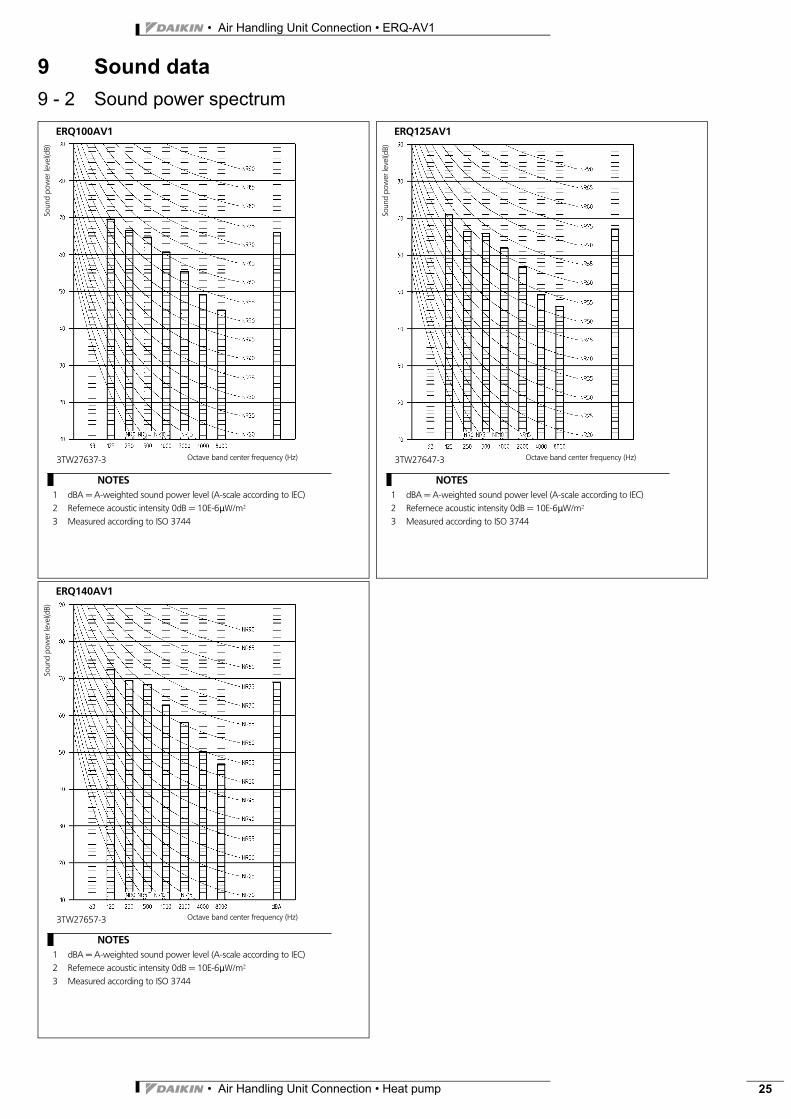
9 Sound data9 - 2 Sound power spectrum
3TW27637-3
Soun
dpo
wer
leve
l(dB)
Octave band center frequency (Hz)
ERQ100AV1
NOTES1 dBA = A-weighted sound power level (A-scale according to IEC)2 Refernece acoustic intensity 0dB = 10E-6μW/m_3 Measured according to ISO 3744
3TW27647-3
Soun
dpo
wer
leve
l(dB)
Octave band center frequency (Hz)
ERQ125AV1
NOTES1 dBA = A-weighted sound power level (A-scale according to IEC)2 Refernece acoustic intensity 0dB = 10E-6μW/m_3 Measured according to ISO 3744
3TW27657-3
Soun
dpo
wer
leve
l(dB)
Octave band center frequency (Hz)
ERQ140AV1
NOTES1 dBA = A-weighted sound power level (A-scale according to IEC)2 Refernece acoustic intensity 0dB = 10E-6μW/m_3 Measured according to ISO 3744
• Air Handling Unit Connection • ERQ-AV1
• Air Handling Unit Connection • Heat pump26
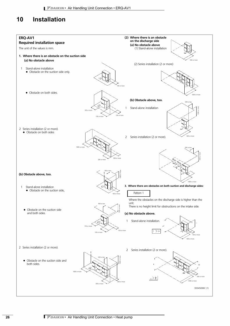
10 Installation
(2) Series installation (2 or more)
(b) Obstacle above, too.
1 Stand-alone installation
2 Series installation (2 or more).
3. Where there are obstacles on both suction and discharge sides:
(a) No obstacle above.
ERQ-AV1Required installation spaceThe unit of the values is mm.
1. Where there is an obstacle on the suction side
+ Obstacle on the suction side andboth sides.
+ Obstacle on the suction sideand both sides.
1 Stand-alone installation.
2 Series installation (2 or more).
(a) No obstacle above
Where the obstacles on the discharge side is higher than theunit.There is no height limit for obstructions on the intake side.
2 Series installation (2 or more).
Pattern 1
2 Series installation (2 or more).+ Obstacle on both sides
(b) Obstacle above, too.
1 Stand-alone installation+ Obstacle on the suction side,.
1 Stand-alone installation+ Obstacle on the suction side only.
(2) Where there is an obstacleon the discharge side
100 or more
100 or more
100 or more
100 or more
300 or more
1000 or more
100 or more
500 or less
150 or more
500 or less
150 or more
150 or more
300 or more
500 or less
200 or more
1000 or more
500 or more
500 or more
1000 or more
1000
orm
ore
500 or less
1000 or more
500 or less
100 or more
500 or more
300 or more
1000
orm
ore
1000
orm
ore
1000
orm
ore
1000
orm
ore
200 or more
+ Obstacle on both sides.
(a) No obstacle above(1) Stand-alone installation
3D045696C (1)
1000 or more
• Air Handling Unit Connection • Heat pump 27
• Air Handling Unit Connection • ERQ-AV1
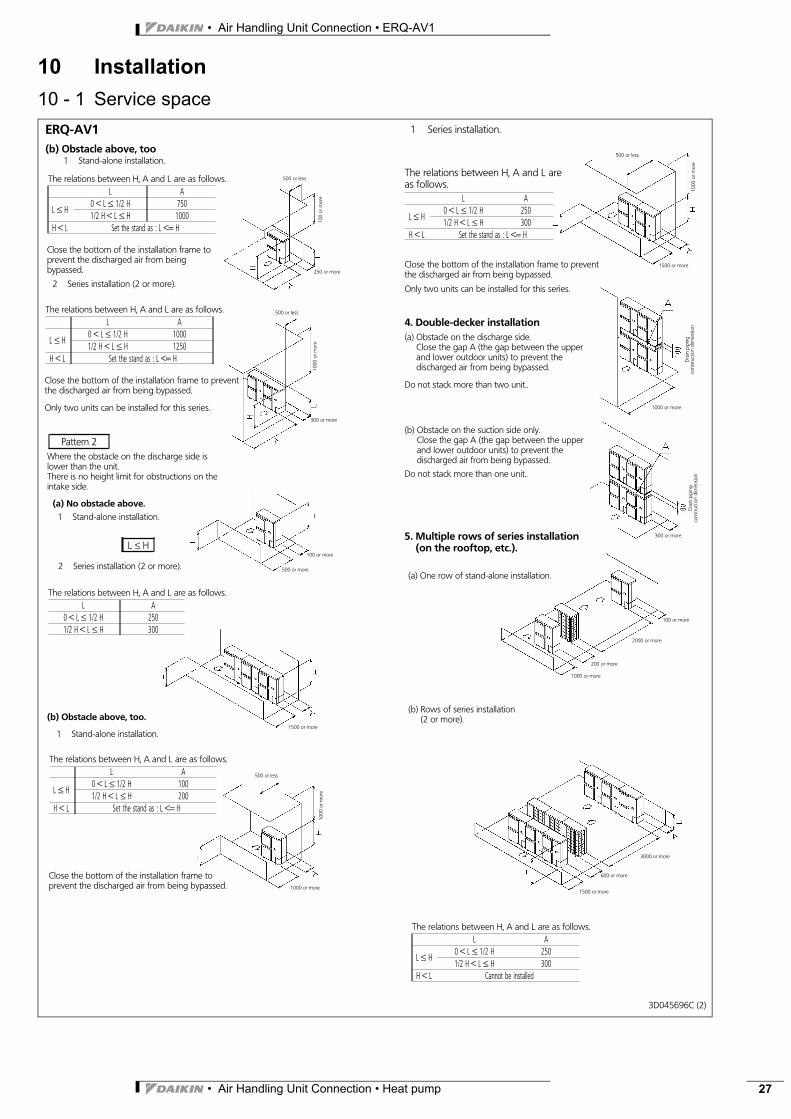
10 Installation10 - 1 Service space
(a) One row of stand-alone installation.
(b) Rows of series installation(2 or more).
1 Series installation.
The relations between H, A and L areas follows.
L A
L ≤ H0 < L ≤ 1/2 H 2501/2 H < L ≤ H 300
H < L Set the stand as : L <= H
4. Double-decker installation(a) Obstacle on the discharge side.
Close the gap A (the gap between the upperand lower outdoor units) to prevent thedischarged air from being bypassed.
Do not stack more than two unit..
The relations between H, A and L are as follows.L A
L ≤ H0 < L ≤ 1/2 H 2501/2 H < L ≤ H 300
H < L Cannot be installed
(b) Obstacle on the suction side only.Close the gap A (the gap between the upperand lower outdoor units) to prevent thedischarged air from being bypassed.
Do not stack more than one unit..
5. Multiple rows of series installation(on the rooftop, etc.).
ERQ-AV1(b) Obstacle above, too
Close the bottom of the installation frame to preventthe discharged air from being bypassed.
Only two units can be installed for this series.
1 Stand-alone installation.
2 Series installation (2 or more).
The relations between H, A and L are as follows.L A
L ≤ H0 < L ≤ 1/2 H 7501/2 H < L ≤ H 1000
H < L Set the stand as : L <= H
The relations between H, A and L are as follows.L A
L ≤ H0 < L ≤ 1/2 H 10001/2 H < L ≤ H 1250
H < L Set the stand as : L <= H
Pattern 2Where the obstacle on the discharge side islower than the unit.There is no height limit for obstructions on theintake side.
(a) No obstacle above.1 Stand-alone installation.
2 Series installation (2 or more).
The relations between H, A and L are as follows.L A
0 < L ≤ 1/2 H 2501/2 H < L ≤ H 300
(b) Obstacle above, too.
1 Stand-alone installation.
The relations between H, A and L are as follows.L A
L ≤ H0 < L ≤ 1/2 H 1001/2 H < L ≤ H 200
H < L Set the stand as : L <= H
Close the bottom of the installation frame toprevent the discharged air from beingbypassed.
Close the bottom of the installation frame toprevent the discharged air from being bypassed.
Close the bottom of the installation frame to preventthe discharged air from being bypassed.
Only two units can be installed for this series.
500 or less
250 or more
500 or less
300 or more
100 or more
500 or more
1500 or more
1000 or more
500 or less
500 or less
1500 or more
Dra
inpi
ping
cons
truct
ion
dim
ensio
n
1000 or more
300 or more
1000 or more
200 or more
2000 or more
100 or more
3000 or more
600 or more
1500 or more
1000
orm
ore
100
orm
ore
1000
orm
ore
1000
orm
ore
3D045696C (2)
L ≤ H
Dra
inpi
ping
cons
truct
ion
dim
ensio
n
• Air Handling Unit Connection • ERQ-AV1
• Air Handling Unit Connection • Heat pump28
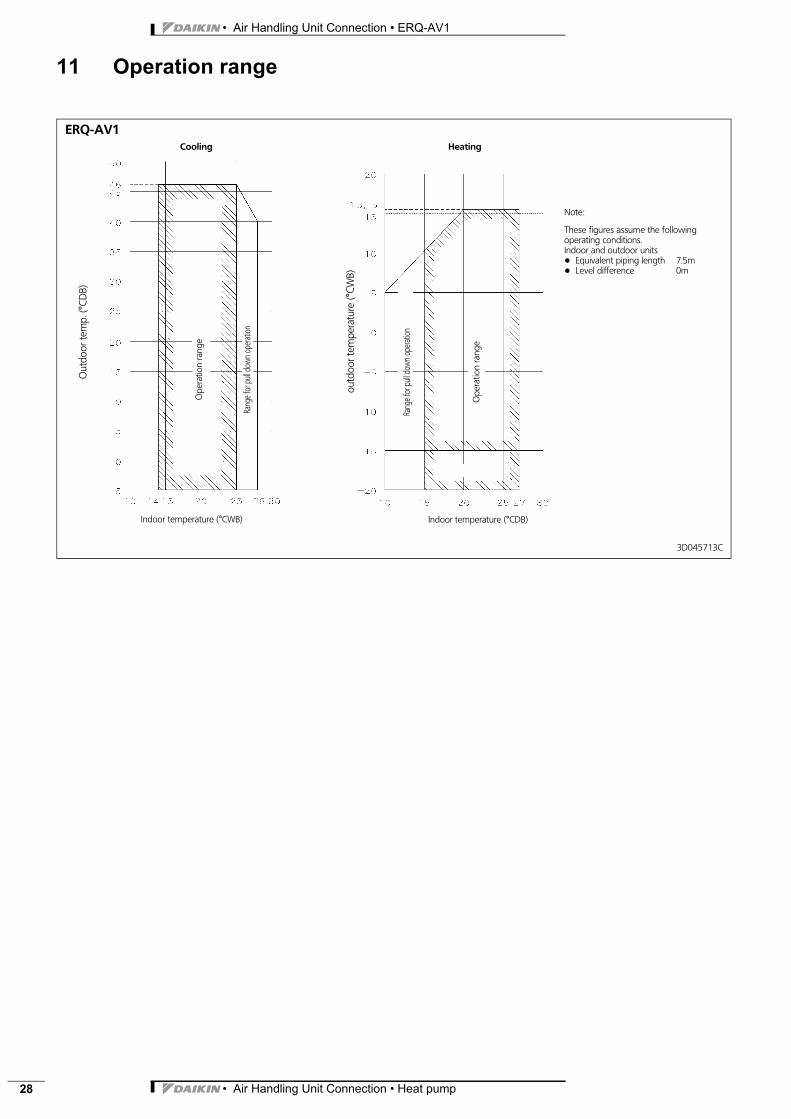
11 Operation range
3D045713C
ERQ-AV1
Out
door
tem
p.(°
CDB)
Indoor temperature (°CWB)
Note:
These figures assume the followingoperating conditions.Indoor and outdoor units+ Equivalent piping length 7.5m+ Level difference 0m
Ope
ratio
nra
nge
Rang
efor
pulld
own
oper
ation
Cooling Heating
Ope
ratio
nra
nge
Rang
efor
pulld
own
oper
ation
Indoor temperature (°CDB)
outd
oort
empe
ratu
re(°
CWB)

Copy
right
Daiki
nPr
epar
ed in
Belg
ium by
Lann
oo (
www.
lanno
oprin
t.be)
, a co
mpan
y who
se co
ncer
n for
the en
viron
mont
is se
t in th
e EMA
S an
d ISO
1400
1 sys
tems.
Resp
onsib
le Ed
itor:
Daiki
n Eur
ope N
.V., Z
andv
oord
estra
at 30
0, B-
8400
Oos
tende
Daikin Europe N.V. is approved by LRQA for its QualityManagement System in accordance with the ISO9001standard. ISO9001 pertains to quality assurance regardingdesign, development, manufacturing as well as to servicesrelated to the product.
Daikin units comply with the European regulations thatguarantee the safety of the product.
The present publication is drawn up by way of information only and does notconstitute an offer binding upon Daikin Europe N.V.. Daikin Europe N.V. hascompiled the content of this publication to the best of its knowledge. Noexpress or implied warranty is given for the completeness, accuracy,reliability or fitness for particular purpose of its content and the products andservices presented therein. Specifications are subject to change withoutprior notice. Daikin Europe N.V. explicitly rejects any liability for any direct orindirect damage, in the broadest sense, arising from or related to the useand/or interpretation of this publication. All content is copyrighted by DaikinEurope N.V..
VRV® products are not within the scope of the Euroventcertification programme.
Naamloze VennootschapZandvoordestraat 300B-8400 Oostende, Belgiumwww.daikin.euBE 0412 120 336RPR Oostende
Daikin’s unique position as a manufacturer of airconditioning equipment, compressors andrefrigerants has led to its close involvement inenvironmental issues. For several years Daikin hashad the intension to become a leader in the provisionof products that have limited impact on theenvironment. This challenge demands the eco designand development of a wide range of products and anenergy management system, resulting in energyconservation and a reduction of waste.
ISO14001 assures an effective environmentalmanagement system in order to help protect human healthand the environment from the potential impact of ouractivities, products and services and to assist inmaintaining and improving the quality of the environment.


![firepump.com.sgfirepump.com.sg/attachments/Firepump... · The Ajax Elite centrifi]gal pump is suitable for handling ... Nominal impeller diameter cm Mechanical arrangement Shaft sealing](https://static.fdocuments.in/doc/165x107/5e75f3f8e5d41d56c3000c4b/the-ajax-elite-centrifigal-pump-is-suitable-for-handling-nominal-impeller-diameter.jpg)


