Technical Data - Home - CraneDude · 138 HSL Link-Belt Cranes Optional Rear---Mounted Fourth Hoist...
40
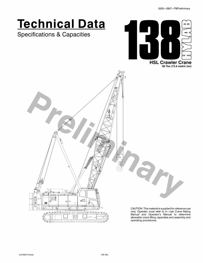
1 5505---0907---P8Preliminary 138 HSL Link-Belt Cranes Technical Dat a Specifications & Capacities HSL Crawler Crane 80 Ton (72.6 metric ton) CAUTION: This material is supplied for reference use only. Operator must refer to in---cab Crane Rating Manual and Operator’s Manual to determine allowable crane lifting capacities and assembly and operating procedures. Link--Belt
Transcript of Technical Data - Home - CraneDude · 138 HSL Link-Belt Cranes Optional Rear---Mounted Fourth Hoist...
15505---0907---P8Preliminary
138 HSLLink-Belt Cranes
Technical DataSpecifications & Capacities
HSL Crawler Crane80 Ton (72.6 metric ton)
CAUTION: Thismaterial is supplied for referenceuseonly. Operator must refer to in---cab Crane RatingManual and Operator’s Manual to determineallowable crane lifting capacities and assembly andoperating procedures.
Link--Belt

5505---0907---P8Preliminary
138 HSL Link-Belt Cranes

5505---0907---P8Preliminary
138 HSLLink-Belt Cranes
Table Of ContentsUpper Structure 1. . . . . . . . . . . . . . . . . . . . . . . . . . . . . . . . . . . . . . . . . . . . . . . . . . . . . . . . . . . . . . . . . . . . . . . . . . . .Frame 1. . . . . . . . . . . . . . . . . . . . . . . . . . . . . . . . . . . . . . . . . . . . . . . . . . . . . . . . . . . . . . . . . . . . . . . . . . . . . . . . . . . .Engine 1. . . . . . . . . . . . . . . . . . . . . . . . . . . . . . . . . . . . . . . . . . . . . . . . . . . . . . . . . . . . . . . . . . . . . . . . . . . . . . . . . . .Hydraulic System 1. . . . . . . . . . . . . . . . . . . . . . . . . . . . . . . . . . . . . . . . . . . . . . . . . . . . . . . . . . . . . . . . . . . . . . . . . .Load Hoist Drums 1. . . . . . . . . . . . . . . . . . . . . . . . . . . . . . . . . . . . . . . . . . . . . . . . . . . . . . . . . . . . . . . . . . . . . . . . .Optional Front---Mounted Third Hoist Drum 1. . . . . . . . . . . . . . . . . . . . . . . . . . . . . . . . . . . . . . . . . . . . . . . . . . .Optional Rear---Mounted Fourth Hoist Drum 2. . . . . . . . . . . . . . . . . . . . . . . . . . . . . . . . . . . . . . . . . . . . . . . . . . .Boom Hoist Drum 2. . . . . . . . . . . . . . . . . . . . . . . . . . . . . . . . . . . . . . . . . . . . . . . . . . . . . . . . . . . . . . . . . . . . . . . . . .Swing System 2. . . . . . . . . . . . . . . . . . . . . . . . . . . . . . . . . . . . . . . . . . . . . . . . . . . . . . . . . . . . . . . . . . . . . . . . . . . . .Counterweight 2. . . . . . . . . . . . . . . . . . . . . . . . . . . . . . . . . . . . . . . . . . . . . . . . . . . . . . . . . . . . . . . . . . . . . . . . . . . .Operator Cab 2. . . . . . . . . . . . . . . . . . . . . . . . . . . . . . . . . . . . . . . . . . . . . . . . . . . . . . . . . . . . . . . . . . . . . . . . . . . . .Rated Capacity Limiter System 2. . . . . . . . . . . . . . . . . . . . . . . . . . . . . . . . . . . . . . . . . . . . . . . . . . . . . . . . . . . . . .Boom Hoist System 2. . . . . . . . . . . . . . . . . . . . . . . . . . . . . . . . . . . . . . . . . . . . . . . . . . . . . . . . . . . . . . . . . . . . . . . .Machinery Cab 2. . . . . . . . . . . . . . . . . . . . . . . . . . . . . . . . . . . . . . . . . . . . . . . . . . . . . . . . . . . . . . . . . . . . . . . . . . . .Catwalks 2. . . . . . . . . . . . . . . . . . . . . . . . . . . . . . . . . . . . . . . . . . . . . . . . . . . . . . . . . . . . . . . . . . . . . . . . . . . . . . . . .Lower Structure 3. . . . . . . . . . . . . . . . . . . . . . . . . . . . . . . . . . . . . . . . . . . . . . . . . . . . . . . . . . . . . . . . . . . . . . . . . . . .Carbody 3. . . . . . . . . . . . . . . . . . . . . . . . . . . . . . . . . . . . . . . . . . . . . . . . . . . . . . . . . . . . . . . . . . . . . . . . . . . . . . . . . .Side Frames 3. . . . . . . . . . . . . . . . . . . . . . . . . . . . . . . . . . . . . . . . . . . . . . . . . . . . . . . . . . . . . . . . . . . . . . . . . . . . . .Travel and Steering 3. . . . . . . . . . . . . . . . . . . . . . . . . . . . . . . . . . . . . . . . . . . . . . . . . . . . . . . . . . . . . . . . . . . . . . . .Optional 3. . . . . . . . . . . . . . . . . . . . . . . . . . . . . . . . . . . . . . . . . . . . . . . . . . . . . . . . . . . . . . . . . . . . . . . . . . . . . . . . . .Attachment and Options 3. . . . . . . . . . . . . . . . . . . . . . . . . . . . . . . . . . . . . . . . . . . . . . . . . . . . . . . . . . . . . . . . . . . .Conventional Tubular Boom 3. . . . . . . . . . . . . . . . . . . . . . . . . . . . . . . . . . . . . . . . . . . . . . . . . . . . . . . . . . . . . . . . .Angle Boom 4. . . . . . . . . . . . . . . . . . . . . . . . . . . . . . . . . . . . . . . . . . . . . . . . . . . . . . . . . . . . . . . . . . . . . . . . . . . . . . .Tubular Jib 4. . . . . . . . . . . . . . . . . . . . . . . . . . . . . . . . . . . . . . . . . . . . . . . . . . . . . . . . . . . . . . . . . . . . . . . . . . . . . . . .Auxiliary Tip Extension 4. . . . . . . . . . . . . . . . . . . . . . . . . . . . . . . . . . . . . . . . . . . . . . . . . . . . . . . . . . . . . . . . . . . . . .Dimensions 5. . . . . . . . . . . . . . . . . . . . . . . . . . . . . . . . . . . . . . . . . . . . . . . . . . . . . . . . . . . . . . . . . . . . . . . . . . . . . . . .Base Crane 7. . . . . . . . . . . . . . . . . . . . . . . . . . . . . . . . . . . . . . . . . . . . . . . . . . . . . . . . . . . . . . . . . . . . . . . . . . . . . . .Side Frames 7. . . . . . . . . . . . . . . . . . . . . . . . . . . . . . . . . . . . . . . . . . . . . . . . . . . . . . . . . . . . . . . . . . . . . . . . . . . . . .Upper Counterweights 8. . . . . . . . . . . . . . . . . . . . . . . . . . . . . . . . . . . . . . . . . . . . . . . . . . . . . . . . . . . . . . . . . . . . .Boom 9. . . . . . . . . . . . . . . . . . . . . . . . . . . . . . . . . . . . . . . . . . . . . . . . . . . . . . . . . . . . . . . . . . . . . . . . . . . . . . . . . . . .Jib 11. . . . . . . . . . . . . . . . . . . . . . . . . . . . . . . . . . . . . . . . . . . . . . . . . . . . . . . . . . . . . . . . . . . . . . . . . . . . . . . . . . . . . . .Hook Balls 12. . . . . . . . . . . . . . . . . . . . . . . . . . . . . . . . . . . . . . . . . . . . . . . . . . . . . . . . . . . . . . . . . . . . . . . . . . . . . . . .Hook Blocks 13. . . . . . . . . . . . . . . . . . . . . . . . . . . . . . . . . . . . . . . . . . . . . . . . . . . . . . . . . . . . . . . . . . . . . . . . . . . . . .Working Weights 13. . . . . . . . . . . . . . . . . . . . . . . . . . . . . . . . . . . . . . . . . . . . . . . . . . . . . . . . . . . . . . . . . . . . . . . . . . .Transport Weights 14. . . . . . . . . . . . . . . . . . . . . . . . . . . . . . . . . . . . . . . . . . . . . . . . . . . . . . . . . . . . . . . . . . . . . . . . . .Transport Drawings -- Tube Boom 15. . . . . . . . . . . . . . . . . . . . . . . . . . . . . . . . . . . . . . . . . . . . . . . . . . . . . . . . . . .Load Hoist Performance 16. . . . . . . . . . . . . . . . . . . . . . . . . . . . . . . . . . . . . . . . . . . . . . . . . . . . . . . . . . . . . . . . . . . .Working Areas 17. . . . . . . . . . . . . . . . . . . . . . . . . . . . . . . . . . . . . . . . . . . . . . . . . . . . . . . . . . . . . . . . . . . . . . . . . . . . .Attachments 18. . . . . . . . . . . . . . . . . . . . . . . . . . . . . . . . . . . . . . . . . . . . . . . . . . . . . . . . . . . . . . . . . . . . . . . . . . . . . . .Tube Boom Make--up 19. . . . . . . . . . . . . . . . . . . . . . . . . . . . . . . . . . . . . . . . . . . . . . . . . . . . . . . . . . . . . . . . . . . . . .Tube Boom Working Range Diagram 20. . . . . . . . . . . . . . . . . . . . . . . . . . . . . . . . . . . . . . . . . . . . . . . . . . . . . . . .Tube Boom Load Chart 21. . . . . . . . . . . . . . . . . . . . . . . . . . . . . . . . . . . . . . . . . . . . . . . . . . . . . . . . . . . . . . . . . . . . .

5505---0907---P8Preliminary
138 HSL Link-Belt Cranes
Angle Boom Make--up 23. . . . . . . . . . . . . . . . . . . . . . . . . . . . . . . . . . . . . . . . . . . . . . . . . . . . . . . . . . . . . . . . . . . . .Angle Boom Working Range Diagram 24. . . . . . . . . . . . . . . . . . . . . . . . . . . . . . . . . . . . . . . . . . . . . . . . . . . . . . .Angle Boom Load Chart 25. . . . . . . . . . . . . . . . . . . . . . . . . . . . . . . . . . . . . . . . . . . . . . . . . . . . . . . . . . . . . . . . . . . .Jib Attachment Make--up 26. . . . . . . . . . . . . . . . . . . . . . . . . . . . . . . . . . . . . . . . . . . . . . . . . . . . . . . . . . . . . . . . . . .Tube Boom + Jib Working Range Diagram 27. . . . . . . . . . . . . . . . . . . . . . . . . . . . . . . . . . . . . . . . . . . . . . . . . . .Tube Boom + Jib Load Charts 28. . . . . . . . . . . . . . . . . . . . . . . . . . . . . . . . . . . . . . . . . . . . . . . . . . . . . . . . . . . . . .Angle Boom + Jib Working Range Diagram 31. . . . . . . . . . . . . . . . . . . . . . . . . . . . . . . . . . . . . . . . . . . . . . . . . .Angle Boom + Jib Load Charts 32. . . . . . . . . . . . . . . . . . . . . . . . . . . . . . . . . . . . . . . . . . . . . . . . . . . . . . . . . . . . .

15505---0907---P8Preliminary
138 HSLLink-Belt Cranes
Upper StructureFrame
All welded steel frame with precisionmachined surfaces for mating parts.
Turntable BearingS Inner race with internal swing gear isbolted to lower frame.
S Outer race bolted to upper frame.
Engine
EngineFull pressure lubrication, oil filter, aircleaner, hour meter, throttle, and electriccontrol shutdown.
Isuzu AH--6HK1X
Number of cylinders 6
Bore and stroke 4.53 x 4.92 in(115 x 125mm)
Piston displacement 475 in3 (7.8L)
Engine rpm at fullload speed 2,000 rpm
Hi---idle rpm 2,050 rpm
Gross engine hp 287 hp (214kw)
Peak torque 838 ft lb (1 125joule)@1,500 rpm
Electrical system 24 volt
Fuel tank capacity 110 gal (415L)
Batteries 2---12 volt
Approximate fuelconsumption gal/hr (L/hr)
100% hp 14.40 (54.51)
75% hp 11.53 (43.65)
50% hp 8.28 (31.34)
25% hp 4.20 (15.90)
Fuel TankEquipped with fuel sight level gauges,flame arrester, and self ---closing cap withlocking eye for padlock.
Hydraulic System
Hydraulic PumpsThe pump arrangement is designed toprovide hydraulically powered functionsallowing positive, precise control with in-dependent or simultaneous operation ofall crane functions.S Two variable displacement pumpsoperating at 4,550 psi (320kg/cm2) and74 gal/min (280L/min) powers loadhoist drums, boomhoist drum, optionalthird drum, optional fourth drum, andtravel.
S One variable displacement pumpoperating at 4,625 psi (325kg/cm2) and31.7 gal/min (120L/min) powers theswing motor and side frame.
S One fixed displacement gear typepump operating at 2,985 psi(210kg/cm2) and 15.9 gal/min (60L/min)powers the remotemounted hydraulicoil cooler fan.
S One fixed displacement gear typepump operating at 1,420 psi(100kg/cm2) and10.8gal/min (41L/min)powers the hydraulic remote controlsystem and hydraulic counterweightself ---assembly system.
S One fixed displacement gear typepump operating at 1,420 psi(100kg/cm2) and 8.4 gal/min (32L/min)powers the optional tagline winch.
Pump Control (“Fine Inching”) ModeSpecial pump setting, selectable from theoperator’s cab, that allows very slowmovements of load hoist drums, boomhoist drum, and travel for precision work.
Hydraulic Reservoir66 gal (250L), equipped with sight levelgauge. Diffusers built in for deaeriation.
FiltrationTenmicron, full flow, line filter in thecontrolcircuit. All oil is filteredprior toentering thereservoir.
Counterbalance ValvesAll hoist motors are equipped with coun-terbalance valves to provide positive loadlowering and prevent accidental loaddrop if the hydraulic pressure is suddenlylost.
Load Hoist Drums
Each drum contains an axial piston, vari-able speed hydraulic motor with individu-al automatic winch motor brakes. Powerflow is directed through a patented,semi---outboard mounted, “wet” stylemulti ---disc brake. The brake is mountedon the “output” side of the planetary,which greatly reduces drag associatedwith most “wet” style brakes in free--- fallmode.S Power up/down & free--- fall operationmodes
S Automatic brakemode (spring applied,hydraulically released, wet type brake)
S Drum lagging grooved for wire ropeS Drum pawl controlled manuallyS Electronic drum rotation indicatorsS Mounted on anti --- friction bearingsS 19.2 in (488mm) root diameterS 33.1 in (840mm) flange diameterS 21.7 in (551mm) widthThe free--- fall operationmode is designedto prevent load lowering even if the free---fall switch is accidentally activated.The automatic brake mode meets allOSHA requirements for personnel han-dling.
Optional Front---MountedThird Hoist Drum
The hydraulic winch is pinned to the frontof theupper frameand isused in conjunc-tion with a fleeting sheave and 3---sheaveidler assembly to run the wire rope overthe boom top section.S Controlled free spooling capability forpile driving applications.
S 10.6 in (270mm) root diameterS 20 in (508mm) flange diameterS 13.5 in (343mm) widthS Mounted on anti --- friction bearings

2 5505---0907---P8Preliminary
138 HSL Link-Belt Cranes
Optional Rear---MountedFourth Hoist Drum
Drum contains an axial piston, variablespeed hydraulic motor with individual au-tomatic winch motor brakes. Power flowisdirected throughapatented, semi---out-board mounted, “wet” style multi ---discbrake.S Power up/down & free--- fall operationmodes
S Automatic brakemode (spring applied,hydraulically released, wet type brake)
S Drum lagging grooved for wire ropeS Drum pawl controlled manuallyS Electronic drum rotation indicatorsS Mounted on anti --- friction bearingsS 19.2 in (488mm) root diameterS 30.7 in (780mm) flange diameterS 19 in (483mm) widthS Pins to rear of upper frameS Plumbing and valving standard withmain unit
The free--- fall operationmode is designedto prevent load lowering even if the free---fall switch is accidentally activated.The automatic brake mode meets allOSHA requirements for personnel han-dling.
Boom Hoist DrumContains a pilot controlled, bi---directional,axial piston motor and a planetary gear re-duction unit to provide positive control un-der all load conditions.S Spring applied, hydraulically released,disc type brake controlled automatically
S 0.63 in (15.88mm) grooved laggingS Drum pawl controlled manuallyS Mounted on anti --- friction bearingsS 17.7 in (450m) root diameterS 28 in (711mm) flange diameterS 8.9 in (226mm) width
Swing System
Mechanically controlled bi---directionalaxial piston motor and planetary gear re-ductionunit to providepositive control un-der all load conditions.S Spring applied, hydraulically released,360˚ multi ---plate brake
S Free swing mode when lever is in neu-tral position
S Two position positive house lockS Audio/Visual swing alarmS Maximum swing speed is 3.0 rpm
Counterweight
Consists of a three---piecedesign that canbe easily lowered to the ground using thegantry.S “A” upper counterweight consists ofone, 23,305 lb (10 571kg) base slab
S “B” upper counterweight consists ofone, 16,943 lb (7 685kg) weight
S “C” upper counterweight consists ofone, 12,071 lb (5 475kg) weight
Total combined counterweight is 52,319 lb(23 732kg).
Operator Cab
Fully enclosed modular steel compart-ment is independently mounted andpadded to protect against vibration andnoise.S All tinted/tempered safety glassS Folding hinge entry door and slidingfront glass window
S 19,000 BTU hot water heaterS 18,600 BTU air conditionerS Door and window locksS Circulating fanS Sun visorS Cloth seatS DefrosterS Windshield wipers and washerS Dry chemical fire extinguisherS Engine instrumentation panel (voltmeter,engine oil pressure, engine water tem-perature, fuel level, hydraulic oil tem-perature, hourmeter, and servicemoni-tor system)
S Electronic drum rotation indicators forfront and rear hoist drums
S Six way adjustable seatS Hand and foot throttleS Fully adjustable single axis controlsS Swing lever with swing brake and hornlocated on handle
S Bubble type levelS Ergonomic gauge layoutS Controls shut off leverS Control stand is adjustable for operatorcomfort.
Rated Capacity LimiterSystem
The HSL rated capacity limiter system is aboom hoist, dead end load cell system.This system provides the operator with use-ful geometrical data, to include:S Main Boom LengthS Main Boom AngleS Jib LengthS Jib AngleS Operating ModeS Load RadiusS Boom Tip HeightS Audible AlarmS Pre---Warning LightS Overload LightS Load On HookS Function kick---outs including over loadS Operator settable stops (rampedstops)S Anti ---Two Block Indicator
Boom Hoist System
Designed to lift off maximum boom ormaximum boom plus jib unassisted. Op-erates up to a maximum boom angle of80˚. Boom hoist limit system limits maxi-mum boom angle operation.S 14---part reeving with 16mm (0.63 in)wire rope
S 22 ft (6.71m) live mastS Bridle assemblyS Two 1.25 in (32mm) pendantsS Dual telescoping type backstopsS Sheaves contain sealed anti --- frictionbearings
S Boomspeed from 25˚ ---70˚ is 34.5 sec-onds with no load. Speed was deter-mined using 80 ft (24.38m) of angleboom.
Machinery Cab
Hinged doors (four on right side, three onleft side) for machinery access. Storage/rigging box located on operator’s side ofupper house. Equipped with rooftop ac-cess ladder and skid resistant finish onroof.
Catwalks
Standardon right and left sides. Catwalksare removable for reduced travel width.

35505---0907---P8Preliminary
138 HSLLink-Belt Cranes
Lower StructureCarbody
Lower FrameAll welded high strength steel [65,000 psi(448.16MPa) yield] box constructionframe with precision machined surfacesfor turntable bearing and rotating joint.S 9 ft 2.3 in (2.80m) overall widthS 11 ft 10.9 in (3.63m) overall length
Side Frames
Side FramesAll welded, precision machined, steelframescanbehydraulically extendedandretracted by ahydraulic cylindermountedin the lower frame.S 14 ft (4.27m) extended gaugeS 8 ft 11 in (2.72m) retracted gaugeS 20 ft 2 in (6.25m) overall lengthS 36 in (0.91m) wide track shoesS Sealed (oil filled) idler and drive plane-taries
S Compact travel drivesS Hydraulic self adjusting tracks
Track RollersS Eleven sealed (oil filled) track rollersperside frame
S Heat treated,mountedonoil filledanti ---friction bearings
TracksHeat treated, self ---cleaning, multiplehinged track shoes joined by one---piecefull floating pins; 52 shoes per side frame
Take Up IdlersCast steel, heat treated, self ---cleaning,mounted on aluminum/bronze bushings.Lubricated through idler shaft.
Travel and Steering
Travel and SteeringEach side frame contains a pilot con-trolled, bi ---directional, axial piston motorandaplanetary gear reductionunit topro-vide positive control under all load condi-tions.S Individual control provides smooth,precise maneuverability including fullcounter---rotation.
S Spring applied, hydraulically releaseddisc type brake controlled automatically
S Maximum travel speed is 1.0 mph(1.61km/h) in high speed and 0.6 mph(1km/h) in low speed.
S Designed to 30% gradeability
OptionalS Rud---o---matic model 1248 taglinewinder for angle boom (double barrel,spring wound, drum type)
Attachment and OptionsConventional Tubular Boom40--200 ft (12.19---60.96m)
Basic Boom40 ft (12.19m) two---piece design thatutilizes a 20 ft (6.10m) base section anda 20 ft (6.10m) open throat top sectionwith in --- line connecting pins on 54 in(1.37m) wide and 44 in (1.12m) deepcenters.S Boom foot on 43.5 in (1.10m) centersS 3 in (7.62cm) diameter chordsS Lugs on base section for self assemblyS Deflector roller on top sectionS Permanent skid pads mounted on topsection to protect head machinery
S Rigid sheave guards
S Five, 18 in (0.46m) root diameter steelsheaves mounted on sealed anti --- fric-tion bearings
S Mechanical boom angle indicator
OptionalHandling system thatmounts in theboombase to allow loading/unloading of coun-terweights or a boom section.
Tube Boom ExtensionsThe following table provides the lengthsavailable and the suggested quantity toobtainmaximumboom in 10 ft (3.05m) in-crements. Midpoint pendant connectionsare required at 80 ft (24.38m) for boomlengths of 170 ft (51.80m) thru 200 ft(60.96m).
Tube BoomExtensions Quantity For Max
Boomft m
10 3.05 1
20 6.10 3
30 9.14 3
S Wear bars on top of each sectionS Appropriate length pendantsS Maximum tip height of 204 ft (62.18m)S Boom connecting pins storage oneachextension
4 5505---0907---P8Preliminary
138 HSL Link-Belt Cranes
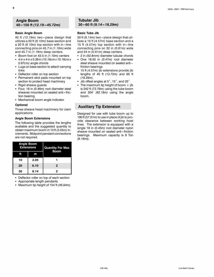
Angle Boom40--150 ft (12.19---45.72m)
Basic Angle Boom40 ft (12.19m) two---piece design thatutilizes a 20 ft (6.10m) base section anda 20 ft (6.10m) top section with in --- lineconnecting pins on 45.7 in (1.16m)wideand 45.7 in (1.16m) deep centers.S Boom foot on 43.5 in (1.10m) centersS 4 in x 4 in x 0.38 in (10.16cm x10.16cm x0.97cm) angle chords
S Lugs on base section to attach carryinglinks
S Deflector roller on top sectionS Permanent skid pads mounted on topsection to protect head machinery
S Rigid sheave guardsS Four, 18 in (0.46m) root diameter steelsheaves mounted on sealed anti --- fric-tion bearing
S Mechanical boom angle indicator
OptionalThree sheave head machinery for clamapplications
Angle Boom ExtensionsThe following table provides the lengthsavailable and the suggested quantity toobtainmaximumboom in 10 ft (3.05m) in-crements. Midpoint pendant connectionsare not required.
Angle BoomExtensions Quantity For Max
Boomft m
10 3.05 1
20 6.10 2
30 9.14 2
S Deflector roller on top of each sectionS Appropriate length pendantsS Maximum tip height of 154 ft (46.94m).
Tubular Jib30--60 ft (9.14---18.29m)
Basic Tube Jib30 ft (9.14m) two---piece design that uti-lizes a 15 ft (4.57m) base section and a15 ft (4.57m) top section with in --- lineconnecting pins on 32 in (0.81m) wideand 24 in (0.61m) deep centers.S 2 in (50.8mm) diameter tubular chordsS One 18.50 in (0.47m) root diametersteel sheave mounted on sealed anti ---friction bearings
S 15 ft (4.57m) jib extensions provide jiblengths of 45 ft (13.72m) and 60 ft(18.29m).
S Jib offset angles at 5˚, 15˚, and 25˚S The maximum tip height of boom + jibis 242 ft (73.76m) using the tube boomand 204’ (62.18m) using the angleboom.
Auxiliary Tip Extension
Designed for use with tube boom up to190 ft (57.91m) touse in place of jib topro-vide clearance between working hoistlines. The extension is equipped with asingle 18 in (0.45m) root diameter nylonsheave mounted on sealed anti --- frictionbearings. Maximum capacity is 9 Ton(8.16mt).

55505---0907---P8Preliminary
138 HSLLink-Belt Cranes
DimensionsGeneral Dimensions English Metric
Basic Boom 40 ft 12.19m
Minimum Load Radius 10 ft 2.75 in 3.19m
Maximum Boom Angle 80˚ 80˚
Track Shoe Width 36 in 0.91m
Maximum height oflive mast from groundis 29’ 2” (8.89m)
8’ 11”(2.72m)
3’ 8”(1.12m)
12’ 2”(3.71m)
14’ 2”(4.32m)
Note: **@ Maximum boom angle (80˚) with maximum boom [200 ft (60.96m)], maximum rotation radius occurs.
23’ 9”**(7.24m)

6 5505---0907---P8Preliminary
138 HSL Link-Belt Cranes
10’ 6”(3.20m)
36”(0.91m)
39”(0.99m)
18’ 11.5” (5.97m) Extended13’ 10.5” (4.23m) Retracted
17’ 0” (5.18m) Extended11’ 11.0” (3.63m) Retracted
14’ 0.5” (4.28m)
10’ 6.3” (3.21m)
Tailswing Radius14’ 2” (4.32m)
15.2”(0.39m)
14’ 0” (4.27m) Extended8’ 11” (2.72m) Retracted

L 2
Number inside black circle “ ” = # of components
Base CraneLength 1 20 ft 2 in (6.15m)Length 2 37 ft 6 in (11.43m)Length 3 2 ft 6 in (0.76m)Height 11 ft 0 in (3.35m)Weight:Tube Boom 88,121 lb (39 971kg)Angle Boom 89,946 lb (40 799kg)
Side FramesLength 20 ft 2 in (6.15m)Width 36 in (0.91m)Height 39 in (0.99m)Weight 19,700 lb (8 936kg)
H
L 1
W
L 3
Base Crane
Side Frames
H
20’ 2”(6.2m)
L
75505---0907---P8Preliminary
138 HSLLink-Belt Cranes

8 5505---0907---P8Preliminary
138 HSL Link-Belt Cranes
“B” Slab CounterweightLength 46 in (1.17m)Width 10 ft 6 in (3.20m)Height 23 in (0.58m)Weight 16,943 lb (7 685kg)
“A” Slab CounterweightLength 46 in (1.17m)Width 10 ft 6 in (3.20m)Height 6 ft 6.25 in (1.99m)Weight 23,305 lb (10 571kg)
Upper Counterweights W
L
H
Number inside black circle “ ” = # of components
“C” Slab CounterweightLength 43.50 in (1.10m)Width 10 ft 6 in (3.20m)Height 25.50 in (0.65m)Weight 12,071 lb (5 475kg)
W
L
H
W
L
H
95505---0907---P8Preliminary
138 HSLLink-Belt Cranes
N6P0001N6P0001
N6P0001N6P0001
N6P0001N6P0001
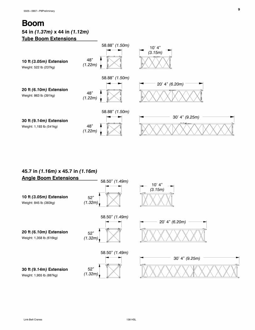
10’ 4”(3.15m)
54 in (1.37m) x 44 in (1.12m)Tube Boom Extensions
30 ft (9.14m) ExtensionWeight: 1,193 lb (541kg)
10 ft (3.05m) ExtensionWeight: 522 lb (237kg)
20 ft (6.10m) ExtensionWeight: 863 lb (391kg)
30’ 4” (9.25m)
20’ 4” (6.20m)
48”(1.22m)
58.88” (1.50m)
Boom
45.7 in (1.16m) x 45.7 in (1.16m)Angle Boom Extensions
30 ft (9.14m) ExtensionWeight: 1,955 lb (887kg)
10 ft (3.05m) ExtensionWeight: 845 lb (383kg)
20 ft (6.10m) ExtensionWeight: 1,358 lb (616kg)
52”(1.32m)
58.50” (1.49m)
48”(1.22m)
58.88” (1.50m)
48”(1.22m)
58.88” (1.50m)
30’ 4” (9.25m)
20’ 4” (6.20m)
10’ 4”(3.15m)
52”(1.32m)
58.50” (1.49m)
52”(1.32m)
58.50” (1.49m)

10 5505---0907---P8Preliminary
138 HSL Link-Belt Cranes
20 ft (6.10m) Tube BoomBase SectionLength 20 ft 6 in (6.25m)Width 58.87 in (1.50m)Deep 44 in (1.12m)Height 61 in (1.55m)Weightw/o Quick Draw 1,701 lb (772kg)w/ Quick Draw 2,211 lb (1 003kg)
L
W
D H
Number inside black circle “ ” = # of components* --- Optional equipment
20 ft (6.10m) Tube BoomTop SectionLength 21 ft 11 in (6.68m)Width 57.13 in (1.45m)Deep 44 in (1.12m)Height 51 in (1.30m)Weight 2,350 lb (1 066kg) D H
W
20 ft (6.10m) Angle BoomTop SectionLength 22 ft 5 in (6.83m)Width 49.06 in (1.25m)Deep 45.7 in (1.16m)Height 50 in (1.27m)Weight 2,937 lb (1 332kg) D
L
H
W
20 ft (6.10m) Angle BoomBase SectionLength 20 ft 6 in (6.25m)Width 50.60 in (1.29m)Deep 45.7 in (1.16m)Height 61 in (1.55m)Weightw/o Quick Draw 2,454 lb (1 113kg)w/ Quick Draw 2,912 lb (1 321kg)
L
W
D H
L

115505---0907---P8Preliminary
138 HSLLink-Belt Cranes
Number inside black circle “ ” = # of components* --- Optional equipment
15 ft (4.57m) JibBase Section*Length 15 ft 3.50 in (4.66m)Width 34.50 in (0.88m)Height 1 26.50 in (0.67m)Height 2 54.50 in (1.38m)Weight† 1,106 lb (502kg)† Weight includes pins, basic frontstay & backstaypendants, and hardware.
15 ft (4.57m) JibExtension*Length 15 ft 2.50 in (4.64m)Width 34.50 in (0.88m)Height 26.50 in (0.67m)Weight† 330 lb (150kg)† Weights includes pins, pendants, and hardware.
W
H 1
LW
H
H 2
L
15 ft (4.57m) JibTop Section*Length 16 ft 1.50 in (4.91m)Width 34.50 in (0.88m)Height 26.50 in (0.67m)Weight† 604 lb (274kg)† Weight includes pendants and hardware.
JibW
L
H
Auxiliary Tip Extension*Length 70.35 in (1.79m)Width 24.50 in (0.62m)Height 42.91 in (1.09m)Weight 720 lb (327kg) L
W
H

12 5505---0907---P8Preliminary
138 HSL Link-Belt Cranes
15 Ton (13.6mt) Non---SwivelHook Ball*Width 18 in (0.46m)Height 39.50 in (1.00m)Weight 748 lb (339kg)
Hook Balls
H
W
15 Ton (13.6mt) SwivelHook Ball*Width 17.50 in (0.44m)Height 40.50 in (1.03m)Weight 767 lb (348kg)
H
W
Number inside black circle “ ” = # of components* --- Optional equipment

135505---0907---P8Preliminary
138 HSLLink-Belt Cranes
80 Ton (72.6mt)4---Sheave Hook Block*Width1 24.75 in (0.63m)Width2 18.25 in (0.46m)Width3 20.25 in (0.51m)Height 60.00 in (1.52m)Weight 1,221 lb (554kg)
Number inside black circle “ ” = # of components* --- Optional equipment
W1 W2Hook Blocks50 Ton (45.4mt)4---Sheave Hook Block*Width1 22.75 in (0.58m)Width2 20.25 in (0.51m)Width3 18.75 in (0.48m)Height 54.00 in (1.37m)Weight 1,221 lb (554kg)
W3
H
W1 W2
W3
H
Working WeightsBased on basic crane including Isuzu AH---6HK1X diesel engine, turntable bearing, livemast, 14 part boom hoist reeving, backstops, crawler lower with 36 in (0.91m) widetrack shoes, sealed track rollers, and catwalks, plus the following:
Ctwt “A” Ctwt “AB” Ctwt “ABC”
lb(kg)
lb(kg)
lb(kg)
Lifting crane --- includes 40 ft (12.19m) basic tubular boom, quickdraw cylinder, 700 ft(213.36m) of 16mm type “DB” front hoist rope, 700 ft (213.36m) of 16mm type “DB” rearhoist rope, 80 Ton (72.6mt) hook block, and basic pendants.
116,388(52 793)
133,332(60 478)
145,403(65 954)
Ground Bearing Pressurepsi
kg/cm2

14 5505---0907---P8Preliminary
138 HSL Link-Belt Cranes
Transport WeightsBase Crane: Rigid Boom Backstops, 27 gal (102.2L) Of Fuel, Side Frames, Catwalks, 20’ (6.10m) Tube Base Section, 24’ (7.32m) Live Mast withBridle & Spreader Bar, 14---Part Boom Hoist Reeving, 700’ (213.36m) Type “DB” Front Hoist Rope, and 700’ (213.36m) Type “DB” Rear Hoist Rope.
Item DescriptionGross Weight Transport Loads
lb kg #1 #2 #3
Base Crane 88,121 39 971 1
Add “A” Counterweight 23,305 10 571 1
Add “B” Counterweight 16,943 7 685 1
Add “C” Counterweight 12,071 5 475 1
Add Hydraulic Third Drum Without Rope 1,345 610
Add 20’ (6.10m) Tube Top Section 2,700 1 225 1
Add 10’ (3.05m) Tube Extension With Pins And Pendants 677 307 1
Add 20’ (6.10m) Tube Extension With Pins And Pendants 1,076 488 1 2
Add 30’ (9.14m) Tube Extension With Pins and Pendants 1,481 672 2 1
Add 20’ (6.10m) Angle Base Section 2,912 1 321Add 20’ (6.10m) Angle Top Section With 4 Lifting Sheaves 3,500 1 588
Add 20’ (6.10m) Angle Top Section With 3 Lifting Sheaves 3,400 1 542Add 20’ (6.10m) Angle Top Section With 2 Lifting Sheaves 3,300 1 497
Add 10’ (3.05m) Angle Extension With Pins And Pendants 992 450Add 20’ (6.10m) Angle Extension With Pins And Pendants 1,625 737
Add 30’ (9.14m) Angle Extension With Pins and Pendants 2,264 1 027Add Tagline Winder 760 345
Add 30’ (9.14m) Tube Jib 1,710 775 1
Add 15’ (4.57m) Tube Jib Extension 330 150 2
Add 5’ (1.52m) Auxiliary Tip Extension 735 333Add Holding Rope --- 7/8 in X 165’ (50.29m) Type “DB” 234 106
Add Closing Rope --- 7/8 in X 220’ (67.06m) Type “DB” 312 142Add Inhaul Rope --- 7/8 in X 105’ (32.00m) Type “M” 141 64
Add Hoist Rope --- 7/8 in X 210’ (64.01m) Type “LB” 298 135
Add Jib Wire Rope --- 7/8 in X 700’ (213.36m) Type “DB” 994 451
Add 3rd Drum Wire Rope --- 16mm X 385’ (117.35m) Type “ZB” 312 142Add 3rd Drum Wire Rope --- 16mm X 385’ (117.35m) Type “WB” 296 134
Add 15---ton (13.6mt) Hook Ball --- Non Swivel 750 340 1
Add 15---ton (13.6mt) Hook Ball --- Swivel 767 348
Add 50---ton (45.3mt) 4 Sheave Hook Block 1,221 554Add 80---ton (72.6mt) 4 Sheave Hook Block 1,221 554 1
Add Quick Draw 510 231Remove 20’ (6.10m) Tube Base Section ---1,988 ---902
Remove Front Hoist Rope --- 7/8 in X 700’ (213.36m) Type “DB” ---944 ---428
Remove Jib Wire Rope --- 7/8 in X 540’ (164.59m) Type “RB” ---1,050 ---476
Remove 22’ (6.71m) Live Mast with Bridle & Spreader ---2,356 ---1 069Remove 50 gal (190L) Of Fuel 362 164
Approximate Total Shipping Weightlb 88,121 37,723 29,932
kg 39 971 17 111 13 578
Notes:Estimated weights vary by ± 2%. Numbers in the transport loads columns represent quantities.Estimated transport loads assume the load out consist of 200’ (60.96m) of tube boom and 60’ (18.29m) of jib with full counterweight.Support loads were targeted at 45,000 lb (20 412kg), 8’ 6” (2.6m) wide, 48’ (14.6m) long, and 13’ 6” (4.1m) high using a drop deck trailer. This may vary depending onstate laws, empty truck/trailer weights, and style of trailer.

155505---0907---P8Preliminary
138 HSLLink-Belt Cranes
Transport Drawings --- Tube Boom
LOAD #1 --- 88,121 lb (39 971kg)Base crane
12’ 7.75”(3.85m)
34”(0.86m)
34”(0.86m)
LOAD #2 --- 37,390 lb (16 960kg)“B” & “C” counterweights, 20 ft (6.10m) tube boom top section, 20 ft (6.10m) tube boomextension with pins and pendants, two 30 ft (9.14m) tube boom extensions with pins andpendants, 15 ton (13.6mt) non---swivel hook ball, and 80 ton (72.6mt) 4 sheave hook block.
34”(0.86m)
12’ 10.75”(3.93m)
13’ 7.25”(4.14m)
LOAD #3 --- 29,792 lb (13 513kg)“A” counterweight and cylinders, 10 ft (3.05m) tube boom extension with pins and pendants, two20 ft (6.10m) tube boom extensions with pins and pendants, 30 ft (9.14m) tube boom extensionwith pins and pendants, 30 ft (9.14m) basic tube jib, and two 15 ft (4.57m) tube jib extensions.
16 5505---0907---P8Preliminary
138 HSL Link-Belt Cranes
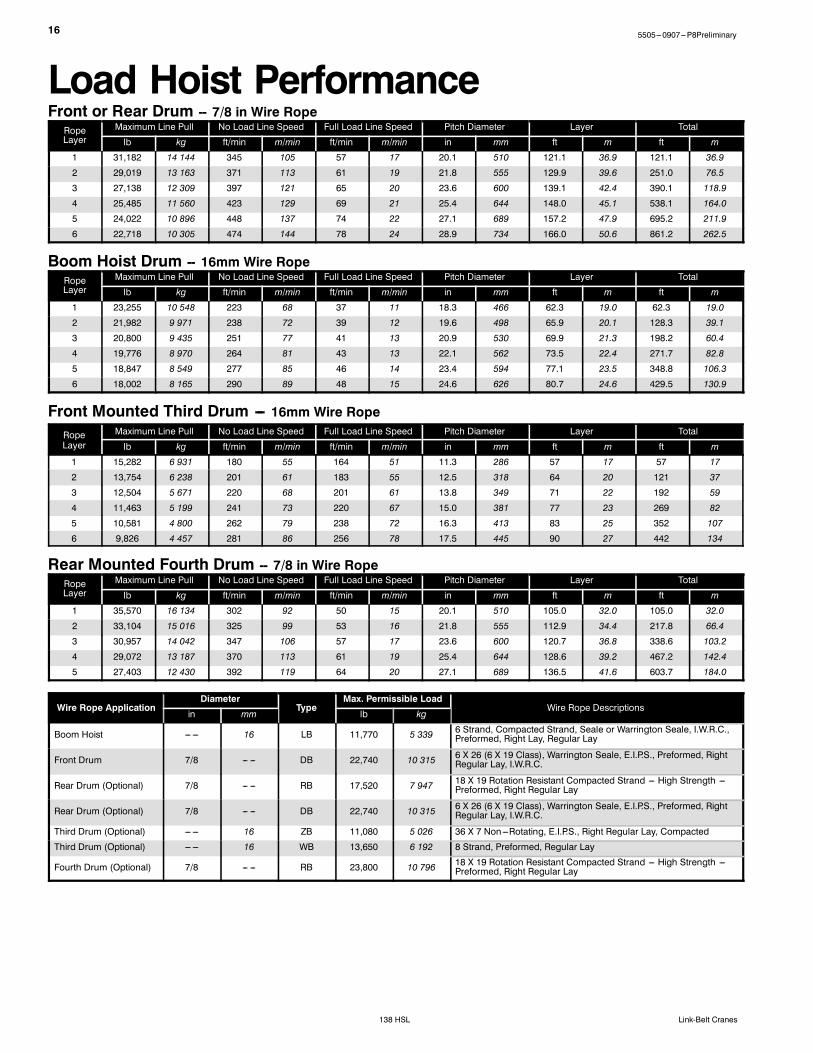
Load Hoist PerformanceFront or Rear Drum -- 7/8 in Wire RopeRopeLayer
Maximum Line Pull No Load Line Speed Full Load Line Speed Pitch Diameter Layer Total
lb kg ft/min m/min ft/min m/min in mm ft m ft m
1 31,182 14 144 345 105 57 17 20.1 510 121.1 36.9 121.1 36.9
2 29,019 13 163 371 113 61 19 21.8 555 129.9 39.6 251.0 76.5
3 27,138 12 309 397 121 65 20 23.6 600 139.1 42.4 390.1 118.9
4 25,485 11 560 423 129 69 21 25.4 644 148.0 45.1 538.1 164.0
5 24,022 10 896 448 137 74 22 27.1 689 157.2 47.9 695.2 211.9
6 22,718 10 305 474 144 78 24 28.9 734 166.0 50.6 861.2 262.5
Boom Hoist Drum -- 16mm Wire RopeRopeLayer
Maximum Line Pull No Load Line Speed Full Load Line Speed Pitch Diameter Layer Total
lb kg ft/min m/min ft/min m/min in mm ft m ft m
1 23,255 10 548 223 68 37 11 18.3 466 62.3 19.0 62.3 19.0
2 21,982 9 971 238 72 39 12 19.6 498 65.9 20.1 128.3 39.1
3 20,800 9 435 251 77 41 13 20.9 530 69.9 21.3 198.2 60.4
4 19,776 8 970 264 81 43 13 22.1 562 73.5 22.4 271.7 82.8
5 18,847 8 549 277 85 46 14 23.4 594 77.1 23.5 348.8 106.3
6 18,002 8 165 290 89 48 15 24.6 626 80.7 24.6 429.5 130.9
Front Mounted Third Drum --- 16mm Wire RopeRopeLayer
Maximum Line Pull No Load Line Speed Full Load Line Speed Pitch Diameter Layer Total
lb kg ft/min m/min ft/min m/min in mm ft m ft m
1 15,282 6 931 180 55 164 51 11.3 286 57 17 57 17
2 13,754 6 238 201 61 183 55 12.5 318 64 20 121 37
3 12,504 5 671 220 68 201 61 13.8 349 71 22 192 59
4 11,463 5 199 241 73 220 67 15.0 381 77 23 269 82
5 10,581 4 800 262 79 238 72 16.3 413 83 25 352 107
6 9,826 4 457 281 86 256 78 17.5 445 90 27 442 134
Rear Mounted Fourth Drum -- 7/8 in Wire RopeRopeLayer
Maximum Line Pull No Load Line Speed Full Load Line Speed Pitch Diameter Layer Total
lb kg ft/min m/min ft/min m/min in mm ft m ft m
1 35,570 16 134 302 92 50 15 20.1 510 105.0 32.0 105.0 32.0
2 33,104 15 016 325 99 53 16 21.8 555 112.9 34.4 217.8 66.4
3 30,957 14 042 347 106 57 17 23.6 600 120.7 36.8 338.6 103.2
4 29,072 13 187 370 113 61 19 25.4 644 128.6 39.2 467.2 142.4
5 27,403 12 430 392 119 64 20 27.1 689 136.5 41.6 603.7 184.0
Wire Rope ApplicationDiameter
TypeMax. Permissible Load
Wire Rope Descriptionsin mm lb kg
Boom Hoist --- --- 16 LB 11,770 5 339 6 Strand, Compacted Strand, Seale or Warrington Seale, I.W.R.C.,Preformed, Right Lay, Regular Lay
Front Drum 7/8 --- --- DB 22,740 10 315 6 X 26 (6 X 19 Class), Warrington Seale, E.I.P.S., Preformed, RightRegular Lay, I.W.R.C.
Rear Drum (Optional) 7/8 --- --- RB 17,520 7 947 18 X 19 Rotation Resistant Compacted Strand --- High Strength ---Preformed, Right Regular Lay
Rear Drum (Optional) 7/8 --- --- DB 22,740 10 315 6 X 26 (6 X 19 Class), Warrington Seale, E.I.P.S., Preformed, RightRegular Lay, I.W.R.C.
Third Drum (Optional) --- --- 16 ZB 11,080 5 026 36 X 7 Non---Rotating, E.I.P.S., Right Regular Lay, Compacted
Third Drum (Optional) --- --- 16 WB 13,650 6 192 8 Strand, Preformed, Regular Lay
Fourth Drum (Optional) 7/8 --- --- RB 23,800 10 796 18 X 19 Rotation Resistant Compacted Strand --- High Strength ---Preformed, Right Regular Lay

175505---0907---P8Preliminary
138 HSLLink-Belt Cranes
Working Areas
Boom
OverIdlerEnd
OverDriveEndCenter Of
Rotation
Drive Sprocket
Of Crawler
Longitudinal
See Note
SeeNote
Idler Sprocket
360˚
Over Side
Note: These Lines Determine The Limiting Position Of Any Load For Operation Within Working Areas Indicated.
Over Side

18 5505---0907---P8Preliminary
138 HSL Link-Belt Cranes
Attachments
40--200 ft(12.19---60.96m)Main Tube Boom
MainBoom
40--150 ft(12.19---45.72m)Main Angle Boom
OffsetJib
MainBoom
Auxiliary TipExtension
40--190 ft (12.19---57.91m)Main Tube Boom With
Tip Extension
40--180 ft (12.19---54.86m) MainTube Boom With 30--60 ft(9.14---18.29m) Offset Jib
MainBoom
Optional AuxiliaryTip Extension
195505---0907---P8Preliminary
138 HSLLink-Belt Cranes
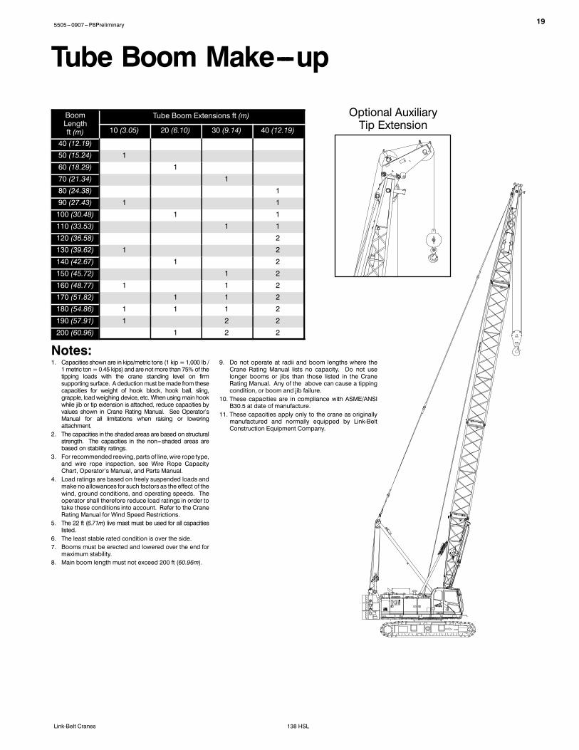
Tube Boom Make---up
BoomLengthft (m)
Tube Boom Extensions ft (m)
10 (3.05) 20 (6.10) 30 (9.14) 40 (12.19)
40 (12.19)50 (15.24) 160 (18.29) 170 (21.34) 180 (24.38) 190 (27.43) 1 1100 (30.48) 1 1110 (33.53) 1 1120 (36.58) 2130 (39.62) 1 2140 (42.67) 1 2150 (45.72) 1 2160 (48.77) 1 1 2170 (51.82) 1 1 2180 (54.86) 1 1 1 2190 (57.91) 1 2 2200 (60.96) 1 2 2
Notes:1. Capacities shownare in kips/metric tons (1 kip =1,000 lb /1metric ton=0.45 kips) and are not more than 75% of thetipping loads with the crane standing level on firmsupporting surface. A deductionmust bemade from thesecapacities for weight of hook block, hook ball, sling,grapple, loadweighing device, etc. When using main hookwhile jib or tip extension is attached, reduce capacities byvalues shown in Crane Rating Manual. See Operator’sManual for all limitations when raising or loweringattachment.
2. The capacities in the shaded areas are based on structuralstrength. The capacities in the non---shaded areas arebased on stability ratings.
3. For recommended reeving, parts of line,wire rope type,and wire rope inspection, see Wire Rope CapacityChart, Operator’s Manual, and Parts Manual.
4. Load ratings are based on freely suspended loads andmake no allowances for such factors as the effect of thewind, ground conditions, and operating speeds. Theoperator shall therefore reduce load ratings in order totake these conditions into account. Refer to the CraneRating Manual for Wind Speed Restrictions.
5. The 22 ft (6.71m) live mast must be used for all capacitieslisted.
6. The least stable rated condition is over the side.7. Booms must be erected and lowered over the end formaximum stability.
8. Main boom length must not exceed 200 ft (60.96m).
9. Do not operate at radii and boom lengths where theCrane Rating Manual lists no capacity. Do not uselonger booms or jibs than those listed in the CraneRating Manual. Any of the above can cause a tippingcondition, or boom and jib failure.
10. These capacities are in compliance with ASME/ANSIB30.5 at date of manufacture.
11. These capacities apply only to the crane as originallymanufactured and normally equipped by Link-BeltConstruction Equipment Company.

20 5505---0907---P8Preliminary
138 HSL Link-Belt Cranes
Tube Boom Working Range Diagram40---200’ Tube Boom
Notes:1. Boom geometry shown is for unloaded condition and crane standing level on firm supporting surface. Boom deflection, subsequent
radius, and boom angle change must be accounted for when applying load to hook.2. Maximum and minimum boom angles are equal to the values listed in the capacity chart for each boom length.
MainBoomLength
LC of Rotation200’180’160’140’120’100’80’60’40’20’
200’
190’
180’
170’
160’
150’
140’
130’
120’
110’
100’
90’
80’
70’
60’
50’
40’
Operating Radius from Centerline of Rotation
0’
10’
20’
30’
40’
50’
60’
70’
80’
90’
100’
110’
120’
130’
140’
150’
160’
170’
180’
190’
200’
210’
HeightAboveGround
Maximum Boom AngleSee Note 2.
Minimum Boom AngleSee Note 2.
80˚
70˚
60˚
50˚
40˚
30˚
20˚

215505---0907---P8Preliminary
138 HSLLink-Belt Cranes
Tube Boom Load ChartTube Boom Lift Capacity Chart -- 360_ Rotation
ABC = 52,319 lb (23 732kg) Counterweight -- Side Frames Extended[All capacities are listed in kips (mt)]
LoadRadiusft (m)
Boom Length --- ft (m)
40(12.2)
50(15.2)
60(18.3)
70(21.3)
80(24.4)
90(27.4)
100(30.5)
110(33.5)
120(36.6)
130(39.6)
11(3.4)
160.0(72.6)
12(3.7)
160.0(72.6)
160.0(72.6)
13(4.0)
151.8(68.9)
151.6(68.8)
14(4.3)
141.6(64.2)
141.4(64.1)
141.1(64.0)
15(4.6)
132.6(60.1)
132.4(60.1)
132.2(60.0)
16(4.9)
124.7(56.6)
124.5(56.5)
124.3(56.4)
123.9(56.2)
17(5.2)
117.6(53.3)
117.5(53.3)
117.3(53.2)
117.0(53.1)
18(5.5)
111.1(50.4)
111.2(50.4)
111.0(50.3)
110.7(50.2)
109.0(49.4)
19(5.8)
101.7(46.1)
101.9(46.2)
102.0(46.3)
102.1(46.3)
102.1(46.3)
99.3(45.0)
20(6.1)
93.7(42.5)
93.9(42.6)
94.0(42.6)
94.1(42.7)
94.1(42.7)
94.0(42.6)
25(7.6)
67.0(30.4)
67.1(30.4)
67.2(30.5)
67.2(30.5)
67.1(30.4)
67.1(30.4)
67.0(30.4)
66.9(30.3)
66.8(30.3)
30(9.1)
51.8(23.5)
51.9(23.5)
52.0(23.6)
52.0(23.6)
51.9(23.5)
51.8(23.5)
51.7(23.5)
51.6(23.4)
51.5(23.4)
51.4(23.3)
35(10.7)
42.0(19.1)
42.2(19.1)
42.2(19.1)
42.1(19.1)
42.1(19.1)
42.0(19.1)
41.9(19.0)
41.8(19.0)
41.6(18.9)
41.5(18.8)
40(12.2)
35.1(15.9)
35.3(16.0)
35.3(16.0)
35.3(16.0)
35.2(16.0)
35.1(15.9)
35.0(15.9)
34.9(15.8)
34.7(15.7)
34.6(15.7)
50(15.2)
26.3(11.9)
26.4(12.0)
26.4(12.0)
26.3(11.9)
26.2(11.9)
26.0(11.8)
25.9(11.7)
25.8(11.7)
25.6(11.6)
60(18.3)
20.8(9.4)
20.7(9.4)
20.6(9.3)
20.4(9.3)
20.3(9.2)
20.2(9.2)
20.0(9.1)
70(21.3)
16.9(7.7)
16.7(7.6)
16.6(7.5)
16.5(7.5)
16.3(7.4)
16.2(7.3)
80(24.4)
14.0(6.4)
13.8(6.3)
13.7(6.2)
13.5(6.1)
13.4(6.1)
90(27.4)
11.7(5.3)
11.6(5.3)
11.4(5.2)
11.3(5.1)
100(30.5)
9.9(4.5)
9.8(4.4)
9.6(4.4)
110(33.5)
8.4(3.8)
8.3(3.8)
120(36.6)
7.1(3.2)
This material is supplied for reference use only. Operator must refer to in---cab Crane Rating Manual and Operator’s Manual to determine allowablecrane lifting capacities and assembly and operating procedures.
22 5505---0907---P8Preliminary
138 HSL Link-Belt Cranes
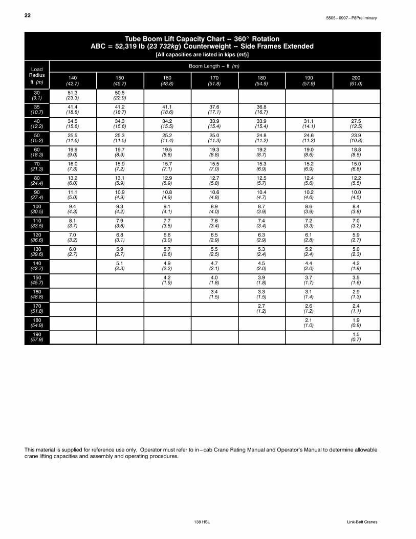
Tube Boom Lift Capacity Chart -- 360_ RotationABC = 52,319 lb (23 732kg) Counterweight -- Side Frames Extended
[All capacities are listed in kips (mt)]
LoadRadiusft (m)
Boom Length --- ft (m)
140(42.7)
150(45.7)
160(48.8)
170(51.8)
180(54.9)
190(57.9)
200(61.0)
30(9.1)
51.3(23.3)
50.5(22.9)
35(10.7)
41.4(18.8)
41.2(18.7)
41.1(18.6)
37.6(17.1)
36.8(16.7)
40(12.2)
34.5(15.6)
34.3(15.6)
34.2(15.5)
33.9(15.4)
33.9(15.4)
31.1(14.1)
27.5(12.5)
50(15.2)
25.5(11.6)
25.3(11.5)
25.2(11.4)
25.0(11.3)
24.8(11.2)
24.6(11.2)
23.9(10.8)
60(18.3)
19.9(9.0)
19.7(8.9)
19.5(8.8)
19.3(8.8)
19.2(8.7)
19.0(8.6)
18.8(8.5)
70(21.3)
16.0(7.3)
15.9(7.2)
15.7(7.1)
15.5(7.0)
15.3(6.9)
15.2(6.9)
15.0(6.8)
80(24.4)
13.2(6.0)
13.1(5.9)
12.9(5.9)
12.7(5.8)
12.5(5.7)
12.4(5.6)
12.2(5.5)
90(27.4)
11.1(5.0)
10.9(4.9)
10.8(4.9)
10.6(4.8)
10.4(4.7)
10.2(4.6)
10.0(4.5)
100(30.5)
9.4(4.3)
9.3(4.2)
9.1(4.1)
8.9(4.0)
8.7(3.9)
8.6(3.9)
8.4(3.8)
110(33.5)
8.1(3.7)
7.9(3.6)
7.7(3.5)
7.6(3.4)
7.4(3.4)
7.2(3.3)
7.0(3.2)
120(36.6)
7.0(3.2)
6.8(3.1)
6.6(3.0)
6.5(2.9)
6.3(2.9)
6.1(2.8)
5.9(2.7)
130(39.6)
6.0(2.7)
5.9(2.7)
5.7(2.6)
5.5(2.5)
5.3(2.4)
5.2(2.4)
5.0(2.3)
140(42.7)
5.1(2.3)
4.9(2.2)
4.7(2.1)
4.5(2.0)
4.4(2.0)
4.2(1.9)
150(45.7)
4.2(1.9)
4.0(1.8)
3.9(1.8)
3.7(1.7)
3.5(1.6)
160(48.8)
3.4(1.5)
3.3(1.5)
3.1(1.4)
2.9(1.3)
170(51.8)
2.7(1.2)
2.6(1.2)
2.4(1.1)
180(54.9)
2.1(1.0)
1.9(0.9)
190(57.9)
1.5(0.7)
This material is supplied for reference use only. Operator must refer to in---cab Crane Rating Manual and Operator’s Manual to determine allowablecrane lifting capacities and assembly and operating procedures.

235505---0907---P8Preliminary
138 HSLLink-Belt Cranes
Angle Boom Make---up
BoomLengthft (m)
Angle Boom Extensions ft (m)
10 (3.05) 20 (6.10) 30 (9.14)
40 (12.19)50 (15.24) 160 (18.29) 170 (21.33) 180 (24.38) 1 190 (27.43) 1 1100 (30.48) 2110 (33.53) 1 2120 (36.58) 1 2130 (39.62) 1 1 2140 (42.67) 2 2150 (45.72) 1 2 2
Notes:3. Capacities shownare in kips/metric tons (1 kip =1,000 lb /1metric ton=0.45 kips) and are not more than 75% of thetipping loads with the crane standing level on firmsupporting surface. A deductionmust bemade from thesecapacities for weight of hook block, hook ball, sling,grapple, loadweighing device, etc. When using main hookwhile jib or tip extension is attached, reduce capacities byvalues shown in Crane Rating Manual. See Operator’sManual for all limitations when raising or loweringattachment.
4. The capacities in the shaded areas are based on structuralstrength. The capacities in the non---shaded areas arebased on stability ratings.
5. For recommended reeving, parts of line,wire rope type,and wire rope inspection, see Wire Rope CapacityChart, Operator’s Manual, and Parts Manual.
6. Load ratings are based on freely suspended loads andmake no allowances for such factors as the effect of thewind, ground conditions, and operating speeds. Theoperator shall therefore reduce load ratings in order totake these conditions into account. Refer to the CraneRating Manual for Wind Speed Restrictions.
7. The 22 ft (6.71m) live mast must be used for all capacitieslisted.
8. The least stable rated condition is over the side.9. Booms must be erected and lowered over the end formaximum stability.
10. Main boom length must not exceed 150 ft (45.72m).

24 5505---0907---P8Preliminary
138 HSL Link-Belt Cranes
Angle Boom Working RangeDiagram
40---150’ Angle Boom
Notes:1. Boom geometry shown is for unloaded condition and crane standing level on firm supporting surface. Boom deflection, subsequent
radius, and boom angle change must be accounted for when applying load to hook.2. Maximum and minimum boom angles are equal to the values listed in the capacity chart for each boom length.
MainBoomLength
LC of Rotation
150’
140’
130’
120’
110’
100’
90’
80’
70’
60’
50’
Operating Radius from Centerline of Rotation
Maximum Boom AngleSee Note 2.
160’140’120’100’80’60’40’20’
40’
160’
150’
140’
130’
120’
110’
100’
90’
80’
70’
60’
50’
40’
30’
20’
10’
0’
HeightAboveGround
Minimum Boom AngleSee Note 2.
80˚
70˚
60˚
50˚
40˚
30˚
20˚

255505---0907---P8Preliminary
138 HSLLink-Belt Cranes
Angle Boom Load ChartAngle Boom Lift Capacity Chart -- 360_ Rotation
ABC = 52,319 lb (23 732kg) Counterweight -- Side Frames Extended[All capacities are listed in kips (mt)]
LoadRadiusft (m)
Boom Length --- ft (m)
40(12.2)
50(15.2)
60(18.3)
70(21.3)
80(24.4)
90(27.4)
100(30.5)
110(33.5)
120(36.6)
130(39.6)
140(42.7)
150(45.7)
11(3.4)
160.0(72.6)
12(3.7)
160.0(72.6)
142.4(64.6)
13(4.0)
151.3(68.6)
137.9(62.6)
14(4.3)
141.1(64.0)
132.8(60.2)
121.7(55.2)
15(4.6)
132.1(59.9)
129.4(58.7)
118.6(53.8)
16(4.9)
124.2(56.3)
123.9(56.2)
116.4(52.8)
105.6(47.9)
17(5.2)
117.1(53.1)
116.9(53.0)
113.5(51.5)
103.0(46.7)
18(5.5)
110.7(50.2)
110.6(50.2)
109.2(49.5)
101.0(45.8)
93.7(42.5)
19(5.8)
101.3(45.9)
101.9(46.2)
101.5(46.0)
98.5(44.7)
92.0(41.7)
84.3(38.2)
20(6.1)
93.3(42.3)
93.4(42.4)
93.5(42.4)
93.4(42.4)
88.5(40.1)
82.7(37.5)
25(7.6)
66.5(30.2)
66.6(30.2)
66.6(30.2)
66.6(30.2)
66.5(30.2)
66.3(30.1)
66.2(30.0)
65.3(29.6)
61.1(27.7)
30(9.1)
51.3(23.3)
51.4(23.3)
51.4(23.3)
51.3(23.3)
51.2(23.2)
51.0(23.1)
50.9(23.1)
50.7(23.0)
50.5(22.9)
50.3(22.8)
49.3(22.4)
44.6(20.2)
35(10.7)
41.6(18.9)
41.6(18.9)
41.6(18.9)
41.5(18.8)
41.3(18.7)
41.2(18.7)
41.0(18.6)
40.8(18.5)
40.6(18.4)
40.4(18.3)
40.2(18.2)
39.9(18.1)
40(12.2)
34.7(15.7)
34.8(15.8)
34.7(15.7)
34.6(15.7)
34.5(15.6)
34.3(15.6)
34.1(15.5)
33.9(15.4)
33.7(15.3)
33.5(15.2)
33.3(15.1)
33.1(15.0)
50(15.2)
25.8(11.7)
25.8(11.7)
25.7(11.7)
25.5(11.6)
25.3(11.5)
25.1(11.4)
24.9(11.3)
24.7(11.2)
24.5(11.1)
24.3(11.0)
24.0(10.9)
60(18.3)
20.3(9.2)
23.7(10.8)
19.9(9.0)
19.7(8.9)
19.5(8.8)
19.3(8.8)
19.1(8.7)
18.9(8.6)
18.6(8.4)
18.4(8.3)
70(21.3)
16.5(7.5)
16.1(7.3)
15.9(7.2)
15.7(7.1)
15.5(7.0)
15.3(6.9)
15.0(6.8)
14.8(6.7)
14.5(6.6)
80(24.4)
13.1(5.9)
12.9(5.9)
12.7(5.8)
12.5(5.7)
12.2(5.5)
12.0(5.4)
11.7(5.3)
90(27.4)
10.8(4.9)
10.6(4.8)
10.3(4.7)
10.1(4.6)
9.9(4.5)
9.6(4.4)
100(30.5)
8.9(4.0)
8.7(3.9)
8.4(3.8)
8.2(3.7)
7.9(3.6)
110(33.5)
7.3(3.3)
7.1(3.2)
6.8(3.1)
6.6(3.0)
120(36.6)
6.0(2.7)
5.7(2.6)
5.5(2.5)
130(39.6)
4.8(2.2)
4.5(2.0)
140(42.7)
3.7(1.7)
This material is supplied for reference use only. Operator must refer to in---cab Crane Rating Manual and Operator’s Manual to determine allowablecrane lifting capacities and assembly and operating procedures.
26 5505---0907---P8Preliminary
138 HSL Link-Belt Cranes
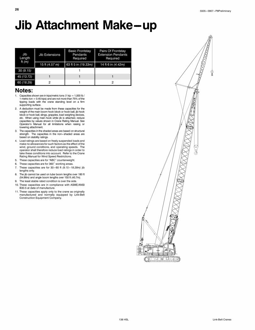
Jib Attachment Make---up
JibLengthft (m)
Jib ExtensionsBasic FrontstayPendantsRequired
Pairs Of FrontstayExtension Pendants
Required
15 ft (4.57 m) 63 ft 5 in (19.33m) 14 ft 6 in (4.42m)
30 (9.15) 1
45 (13.72) 1 1 1
60 (18.29) 2 1 2
Notes:1. Capacities shownare in kips/metric tons (1 kip =1,000 lb /1metric ton=0.45 kips) and are not more than 75% of thetipping loads with the crane standing level on a firmsupporting surface.
2. A deduction must be made from these capacities for theweight of themain boomhook block or hook ball, jib hookblock or hook ball, slings, grapples, load weighing devices,etc. When using main hook while jib is attached, reducecapacities by values shown in Crane Rating Manual. SeeOperator’s Manual for all limitations when raising orlowering attachment.
3. The capacities in the shaded areas are based on structuralstrength. The capacities in the non---shaded areas arebased on stability ratings.
4. Load ratings are based on freely suspended loads andmake no allowances for such factors as the effect of thewind, ground conditions, and operating speeds. Theoperator shall therefore reduce load ratings in order totake these conditions into account. Refer to the CraneRating Manual for Wind Speed Restrictions.
5. These capacities are for “ABC” counterweight.6. These capacities are for 360˚ working areas.7. These capacities are for 30---60 ft (9.15---18.28m) jiblengths only.
8. The jib cannot be used on tube boom lengths over 180 ft(54.86m) and angle boom lengths over 150 ft (45.7m).
9. The least stable rated condition is over the side.10. These capacities are in compliance with ASME/ANSIB30.5 at date of manufacture.
11. These capacities apply only to the crane as originallymanufactured and normally equipped by Link-BeltConstruction Equipment Company.
275505---0907---P8Preliminary
138 HSLLink-Belt Cranes
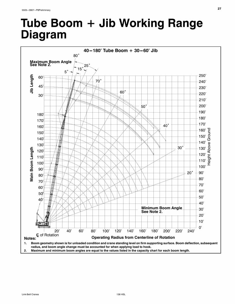
Tube Boom + Jib Working RangeDiagram
Notes:1. Boom geometry shown is for unloaded condition and crane standing level on firm supporting surface. Boom deflection, subsequent
radius, and boom angle change must be accounted for when applying load to hook.2. Maximum and minimum boom angles are equal to the values listed in the capacity chart for each boom length.
40---180’ Tube Boom + 30---60’ Jib80˚
25˚15˚
5˚
MainBoomLength
Operating Radius from Centerline of Rotation
Maximum Boom AngleSee Note 2.
JibLength
HeightAboveGround
LC of Rotation
60’
45’
30’
180’170’160’150’140’130’120’110’100’90’80’70’60’50’40’
200’180’160’140’120’100’80’60’40’20’ 220’ 240’0’10’20’30’40’50’60’70’80’90’100’110’120’130’140’150’
160’170’180’190’200’210’220’230’240’250’
Minimum Boom AngleSee Note 2.
70˚
60˚
50˚
40˚
30˚
20˚

28 5505---0907---P8Preliminary
138 HSL Link-Belt Cranes
Tube Boom + Jib Load ChartsTube Boom + 30 ft (9.14m) Offset Jib Length --- 360_ Rotation
ABC [52,319 lb (23,732kg)] Counterweight[All capacities are listed in kips (mt)]
5˚ Offset 15˚ Offset 25˚ Offset
LoadRadiusft (m)
Main Boom Length ft (m) LoadRadiusft (m)
Main Boom Length ft (m) LoadRadiusft (m)
Main Boom Length ft (m)
40(12.2)
80(24.3)
100(30.5)
140(42.7)
180(54.9)
40(12.2)
80(24.3)
100(30.5)
140(42.7)
180(54.9)
40(12.2)
80(24.3)
100(30.5)
140(42.7)
180(54.9)
20 24.0 20 20
(6.1) (10.9) (6.1) (6.1)
25 24.0 25 24.0 25
(7.6) (10.9) (7.6) (10.9) (7.6)
30 24.0 24.0 24.0 30 24.0 30 19.8
(9.1) (10.9) (10.9) (10.9) (9.1) (10.9) (9.1) (9.0)
35 24.0 24.0 24.0 35 23.8 24.0 24.0 35 17.8 20.6
(10.7) (10.9) (10.9) (10.9) (10.7) (10.8) (10.9) (10.9) (10.7) (8.1) (9.3)
40 24.0 24.0 24.0 24.0 40 21.2 24.0 24.0 40 17.0 19.2 20.2
(12.2) (10.9) (10.9) (10.9) (10.9) (12.2) (9.6) (10.9) (10.9) (12.2) (7.7) (8.7) (9.2)
50 21.1 24.0 24.0 24.0 18.1 50 17.4 23.2 24.0 24.0 17.1 50 14.8 17.3 18.0 19.6
(15.2) (9.6) (10.9) (10.9) (10.9) (8.2) (15.2) (7.9) (10.5) (10.9) (10.9) (7.8) (15.2) (6.7) (7.8) (8.2) (8.9)
60 17.4 20.7 20.4 19.7 17.4 60 16.3 21.0 20.7 20.0 16.3 60 13.3 16.1 17.1 18.0 14.6
(18.3) (7.9) (9.4) (9.3) (8.9) (7.9) (18.9) (7.4) (9.5) (9.4) (9.1) (7.4) (18.9) (6.0) (7.3) (7.8) (8.2) (6.6)
70 16.9 16.5 15.8 15.1 70 17.1 16.8 16.1 15.4 70 14.8 15.8 16.4 14.0
(21.3) (7.7) (7.5) (7.2) (6.8) (21.3) (7.8) (7.6) (7.3) (7.0) (21.3) (6.7) (7.2) (7.4) (6.4)
80 14.1 13.7 13.0 12.3 80 14.2 13.9 13.2 12.6 80 14.4 14.1 13.5 12.8
(24.4) (6.4) (6.2) (5.9) (5.6) (24.8) (6.4) (6.3) (6.0) (5.7) (24.8) (6.5) (6.4) (6.1) (5.8)
90 12.0 11.6 10.9 10.1 90 12.1 11.8 11.1 10.4 90 12.2 11.9 11.2 10.6
(27.4) (5.4) (5.3) (4.9) (4.6) (27.4) (5.5) (5.4) (5.0) (4.7) (27.4) (5.5) (5.4) (5.1) (4.8)
100 10.3 10.0 9.2 8.4 100 10.4 10.1 9.4 8.6 100 10.1 9.5 8.8
(30.5) (4.7) (4.5) (4.2) (3.8) (30.5) (4.7) (4.6) (4.3) (3.9) (30.5) (4.6) (4.3) (4.0)
110 8.6 7.8 7.1 110 8.7 8.0 7.3 110 8.1 7.4
(33.5) (3.9) (3.5) (3.2) (33.5) (3.9) (3.6) (3.3) (33.5) (3.7) (3.4)
120 7.5 6.7 5.9 120 6.8 6.1 120 6.9 6.3
(36.6) (3.4) (3.0) (2.7) (36.6) (3.1) (2.8) (36.6) (3.1) (2.9)
130 5.8 5.0 130 5.9 5.2 130 6.0 5.3
(39.6) (2.6) (2.3) (39.6) (2.7) (2.4) (39.6) (2.7) (2.4)
140 5.0 4.2 140 5.1 4.3 140 4.4
(42.7) (2.3) (1.9) (42.7) (2.3) (2.0) (4267) (2.0)
150 4.3 3.5 150 4.4 3.6 150 3.7
(45.7) (2.0) (1.6) (45.7) (2.0) (1.6) (45.7) (1.7)
160 3.7 2.9 160 3.0 160 3.1
(48.8) (1.7) (1.3) (48.8) (1.4) (4887) (1.4)
170 2.4 170 2.5 170
(51.8) (1.1) (51.8) (1.1) (51.8)
180 2.0 180 2.0 180
(54.9) (0.9) (54.9) (0.9) (54.9)
190 1.6 190 190
(57.9) (0.7) (57.9) (57.9)
This material is supplied for reference use only. Operator must refer to in---cab Crane Rating Manual and Operator’s Manual to determine allowablecrane lifting capacities and assembly and operating procedures.

295505---0907---P8Preliminary
138 HSLLink-Belt Cranes
Tube Boom + 45 ft (13.7m) Offset Jib Length --- 360_ RotationABC [52,319 lb (23,732kg)] Counterweight
[All capacities are listed in kips (mt)]5˚ Offset 15˚ Offset 25˚ Offset
LoadRadiusft (m)
Main Boom Length ft (m) LoadRadiusft (m)
Main Boom Length ft (m) LoadRadiusft (m)
Main Boom Length ft (m)
40(12.2)
80(24.3)
100(30.5)
140(42.7)
180(54.9)
40(12.2)
80(24.3)
100(30.5)
140(42.7)
180(54.9)
40(12.2)
80(24.3)
100(30.5)
140(42.7)
180(54.9)
25 24.0 25 25
(7.6) (10.9) (7.6) (7.6)
30 24.0 24.0 30 19.2 30
(9.1) (10.9) (10.9) (9.1) (8.7) (9.1)
35 21.8 24.0 24.0 35 17.3 35
(10.7) (9.9) (10.9) (10.9) (10.7) (7.8) (10.7)
40 19.1 24.0 24.0 24.0 40 16.7 18.2 40 12.6
(12.2) (8.7) (10.9) (10.9) (10.9) (12.2) (7.6) (8.3) (12.2) (5.7)
50 16.7 20.8 22.9 22.2 15.9 50 13.6 17.2 17.3 18.4 50 10.6 12.3 12.9
(15.2) (7.6) (9.4) (10.4) (10.1) (7.2) (15.2) (6.2) (7.8) (7.8) (8.3) (15.2) (4.8) (5.6) (5.9)
60 13.7 17.5 20.5 19.8 15.3 60 11.5 14.8 16.2 17.2 13.8 60 9.2 11.0 11.6 12.6
(18.3) (6.2) (7.9) (9.3) (9.0) (6.9) (18.9) (5.2) (6.7) (7.3) (7.8) (6.3) (18.9) (4.2) (5.0) (5.3) (5.7)
70 11.7 17.0 16.7 16.0 14.7 70 10.0 13.1 14.3 16.4 13.3 70 8.2 9.9 10.6 11.6 11.3
(21.3) (5.3) (7.7) (7.6) (7.3) (6.7) (21.3) (4.5) (5.9) (6.5) (7.4) (6.0) (21.3) (3.7) (4.5) (4.8) (5.3) (5.1)
80 10.2 14.2 13.9 13.1 12.4 80 11.7 12.9 13.5 12.8 80 9.1 9.8 10.8 10.8
(24.4) (4.6) (6.4) (6.3) (5.9) (5.6) (24.8) (5.3) (5.9) (6.1) (5.8) (24.8) (4.1) (4.4) (4.9) (4.9)
90 12.1 11.7 11.0 10.2 90 10.6 12.0 11.3 10.6 90 8.5 9.1 10.1 10.5
(27.4) (5.5) (5.3) (5.0) (4.6) (27.4) (4.8) (5.4) (5.1) (4.8) (27.4) (3.9) (4.1) (4.6) (4.8)
100 10.5 10.1 9.3 8.5 100 9.8 10.2 9.6 8.9 100 8.0 8.5 9.8 9.2
(30.5) (4.8) (4.6) (4.2) (3.9) (30.5) (4.4) (4.6) (4.4) (4.0) (30.5) (3.6) (3.9) (4.4) (4.2)
110 9.1 8.7 7.9 7.2 110 9.2 8.9 8.2 7.5 110 8.1 8.4 7.7
(33.5) (4.1) (3.9) (3.6) (3.3) (33.5) (4.2) (4.0) (3.7) (3.4) (33.5) (3.7) (3.8) (3.5)
120 8.0 7.6 6.8 6.0 120 7.7 7.0 6.3 120 7.8 7.2 6.5
(36.6) (3.6) (3.4) (3.1) (2.7) (36.6) (3.5) (3.2) (2.9) (36.6) (3.5) (3.3) (2.9)
130 6.7 5.9 5.1 130 6.8 6.1 5.3 130 6.2 5.5
(39.6) (3.0) (2.7) (2.3) (39.6) (3.1) (2.8) (2.4) (39.6) (2.8) (2.5)
140 5.1 4.3 140 5.2 4.5 140 5.3 4.7
(42.7) (2.3) (2.0) (42.7) (2.4) (2.0) (4267) (2.4) (2.1)
150 4.4 3.6 150 4.5 3.8 150 4.6 3.9
(45.7) (2.0) (1.6) (45.7) (2.0) (1.7) (45.7) (2.1) (1.8)
160 3.8 3.0 160 3.9 3.2 160 3.3
(48.8) (1.7) (1.4) (48.8) (1.8) (1.5) (4887) (1.5)
170 3.3 2.5 170 2.6 170 2.7
(51.8) (1.5) (1.1) (51.8) (1.2) (51.8) (1.2)
180 2.0 180 2.2 180 2.2
(54.9) (0.9) (54.9) (1.0) (54.9) (1.0)
190 1.6 190 1.7 190
(57.9) (0.7) (57.9) (0.8) (57.9)
This material is supplied for reference use only. Operator must refer to in---cab Crane Rating Manual and Operator’s Manual to determine allowablecrane lifting capacities and assembly and operating procedures.

30 5505---0907---P8Preliminary
138 HSL Link-Belt Cranes
Tube Boom + 60 ft (18.3m) Offset Jib Length --- 360_ RotationABC [52,319 lb (23,732kg)] Counterweight
[All capacities are listed in kips (mt)]5˚ Offset 15˚ Offset 25˚ Offset
LoadRadiusft (m)
Main Boom Length ft (m) LoadRadiusft (m)
Main Boom Length ft (m) LoadRadiusft (m)
Main Boom Length ft (m)
40(12.2)
80(24.3)
100(30.5)
140(42.7)
180(54.9)
40(12.2)
80(24.3)
100(30.5)
140(42.7)
180(54.9)
40(12.2)
80(24.3)
100(30.5)
140(42.7)
180(54.9)
30 21.2 30 30
(9.1) (9.6) (9.1) (9.1)
35 18.3 23.0 35 35
(10.7) (8.3) (10.4) (10.7) (10.7)
40 17.3 20.4 22.3 40 13.8 40
(12.2) (7.8) (9.3) (10.1) (12.2) (6.3) (12.2)
50 13.8 17.3 18.3 19.0 50 11.2 13.4 14.3 50 8.6
(15.2) (6.3) (7.8) (8.3) (8.6) (15.2) (5.1) (6.1) (6.5) (15.2) (3.9)
60 11.3 15.3 17.1 17.2 13.4 60 9.4 11.6 12.4 13.9 60 7.4 8.4 8.8
(18.3) (5.1) (6.9) (7.8) (7.8) (6.1) (18.9) (4.3) (5.3) (5.6) (6.3) (18.9) (3.4) (3.8) (4.0)
70 9.6 13.0 14.7 15.2 12.9 70 8.1 10.1 11.0 12.4 11.2 70 6.5 7.6 8.0 8.6 8.9
(21.3) (4.4) (5.9) (6.7) (6.9) (5.9) (21.3) (3.7) (4.6) (5.0) (5.6) (5.1) (21.3) (2.9) (3.4) (3.6) (3.9) (4.0)
80 8.3 11.3 12.8 13.2 12.4 80 7.1 9.0 9.8 11.2 10.8 80 5.8 6.9 7.3 8.0 8.5
(24.4) (3.8) (5.1) (5.8) (6.0) (5.6) (24.8) (3.2) (4.1) (4.4) (5.1) (4.9) (24.8) (2.6) (3.1) (3.3) (3.6) (3.9)
90 7.3 10.0 11.8 11.1 10.3 90 6.4 8.1 8.9 10.3 10.5 90 6.3 6.7 7.4 7.9
(27.4) (3.3) (4.5) (5.4) (5.0) (4.7) (27.4) (2.9) (3.7) (4.0) (4.7) (4.8) (27.4) (2.9) (3.0) (3.4) (3.6)
100 9.0 10.1 9.4 8.6 100 7.4 8.1 9.7 9.0 100 5.9 6.3 6.9 7.5
(30.5) (4.1) (4.6) (4.3) (3.9) (30.5) (3.4) (3.7) (4.4) (4.1) (30.5) (2.7) (2.9) (3.1) (3.4)
110 8.1 8.8 8.0 7.2 110 6.8 7.5 8.3 7.6 110 5.5 5.9 6.5 7.1
(33.5) (3.7) (4.0) (3.6) (3.3) (33.5) (3.1) (3.4) (3.8) (3.4) (33.5) (2.5) (2.7) (2.9) (3.2)
120 7.4 7.7 6.9 6.1 120 6.3 7.0 7.1 6.4 120 5.6 6.2 6.8
(36.6) (3.4) (3.5) (3.1) (2.8) (36.6) (2.9) (3.2) (3.2) (2.9) (36.6) (2.5) (2.8) (3.1)
130 7.1 6.7 6.0 5.2 130 6.9 6.2 5.5 130 5.3 5.7 5.7
(39.6) (3.2) (3.0) (2.7) (2.4) (39.6) (3.1) (2.8) (2.5) (39.6) (2.4) (2.6) (2.6)
140 6.0 5.2 4.4 140 6.1 5.3 4.6 140 5.5 4.9
(42.7) (2.7) (2.4) (2.0) (42.7) (2.8) (2.4) (2.1) (4267) (2.5) (2.2)
150 5.3 4.5 3.7 150 4.6 3.9 150 4.8 4.1
(45.7) (2.4) (2.0) (1.7) (45.7) (2.1) (1.8) (45.7) (2.2) (1.9)
160 3.9 3.1 160 4.0 3.3 160 4.1 3.5
(48.8) (1.8) (1.4) (48.8) (1.8) (1.5) (4887) (1.9) (1.6)
170 3.4 2.6 170 3.5 2.7 170 2.9
(51.8) (1.5) (1.2) (51.8) (1.6) (1.2) (51.8) (1.3)
180 2.9 2.1 180 3.0 2.2 180 2.4
(54.9) (1.3) (1.0) (54.9) (1.4) (1.0) (54.9) (1.1)
190 2.5 1.7 190 1.8 190 1.9
(57.9) (1.1) (0.8) (57.9) (0.8) (57.9) (0.9)
This material is supplied for reference use only. Operator must refer to in---cab Crane Rating Manual and Operator’s Manual to determine allowablecrane lifting capacities and assembly and operating procedures.

315505---0907---P8Preliminary
138 HSLLink-Belt Cranes
Angle Boom + Jib Working RangeDiagram
40---150’ Angle Boom + 30---60’ Jib
Notes:1. Boom geometry shown is for unloaded condition and crane standing level on firm supporting surface. Boom deflection, subsequent
radius, and boom angle change must be accounted for when applying load to hook.2. Maximum and minimum boom angles are equal to the values listed in the capacity chart for each boom length.
Maximum Boom AngleSee Note 2.
40’
50’
60’
70’
80’
90’
100’
110’
120’
130’
140’
150’
MainBoomLength
JibLength
30’
45’
60’
HeightAboveGround
0’
10’
20’
30’
40’
50’
60’
70’
80’
90’
100’
110’
120’
130’
140’
150’
160’
170’
180’
190’
200’
210’
220’
20’ 40’ 60’ 80’ 100’ 120’ 140’ 160’
Operating Radius from Centerline of RotationLC of Rotation
180’ 200’ 220’
Minimum Boom AngleSee Note 2.
80˚
70˚
60˚
50˚
40˚
30˚
20˚
25˚15˚
5˚
32 5505---0907---P8Preliminary
138 HSL Link-Belt Cranes
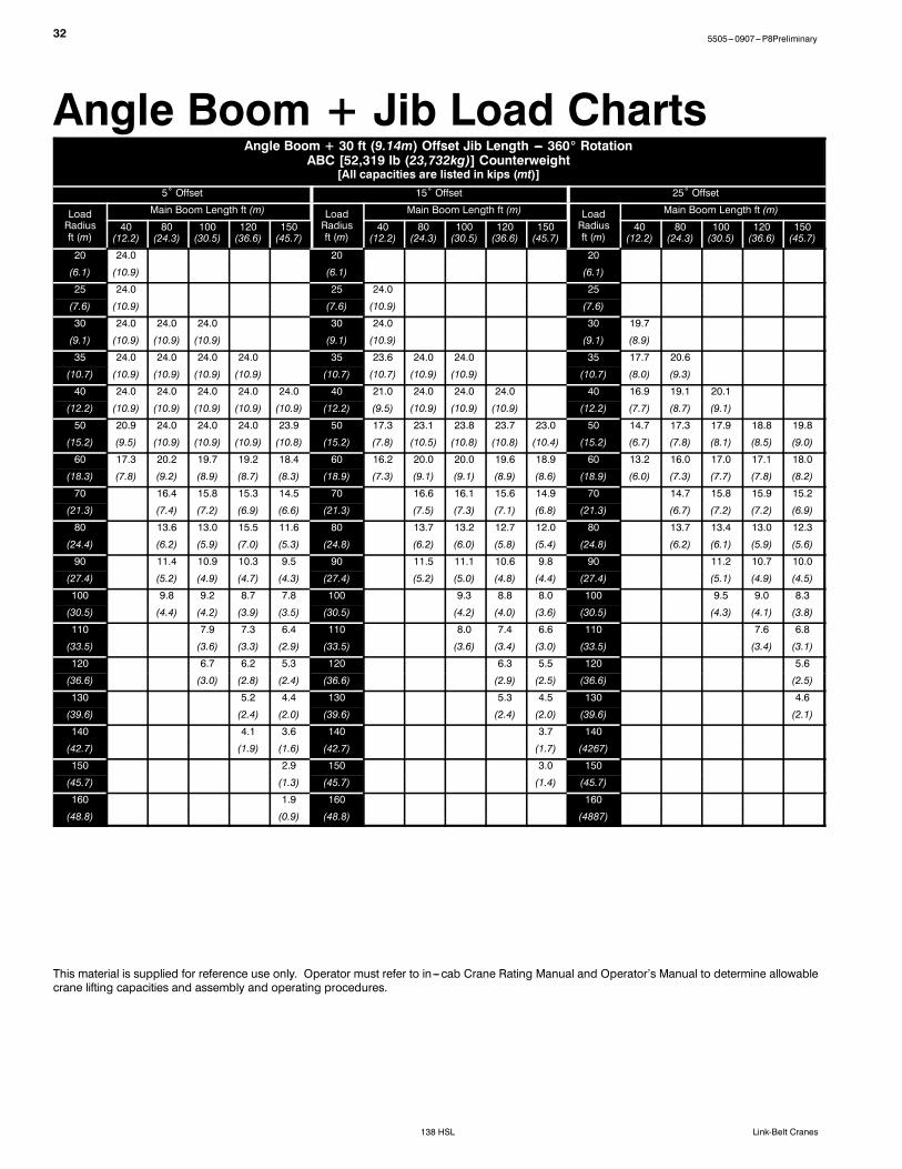
Angle Boom + Jib Load ChartsAngle Boom + 30 ft (9.14m) Offset Jib Length --- 360_ Rotation
ABC [52,319 lb (23,732kg)] Counterweight[All capacities are listed in kips (mt)]
5˚ Offset 15˚ Offset 25˚ Offset
LoadRadiusft (m)
Main Boom Length ft (m) LoadRadiusft (m)
Main Boom Length ft (m) LoadRadiusft (m)
Main Boom Length ft (m)
40(12.2)
80(24.3)
100(30.5)
120(36.6)
150(45.7)
40(12.2)
80(24.3)
100(30.5)
120(36.6)
150(45.7)
40(12.2)
80(24.3)
100(30.5)
120(36.6)
150(45.7)
20 24.0 20 20
(6.1) (10.9) (6.1) (6.1)
25 24.0 25 24.0 25
(7.6) (10.9) (7.6) (10.9) (7.6)
30 24.0 24.0 24.0 30 24.0 30 19.7
(9.1) (10.9) (10.9) (10.9) (9.1) (10.9) (9.1) (8.9)
35 24.0 24.0 24.0 24.0 35 23.6 24.0 24.0 35 17.7 20.6
(10.7) (10.9) (10.9) (10.9) (10.9) (10.7) (10.7) (10.9) (10.9) (10.7) (8.0) (9.3)
40 24.0 24.0 24.0 24.0 24.0 40 21.0 24.0 24.0 24.0 40 16.9 19.1 20.1
(12.2) (10.9) (10.9) (10.9) (10.9) (10.9) (12.2) (9.5) (10.9) (10.9) (10.9) (12.2) (7.7) (8.7) (9.1)
50 20.9 24.0 24.0 24.0 23.9 50 17.3 23.1 23.8 23.7 23.0 50 14.7 17.3 17.9 18.8 19.8
(15.2) (9.5) (10.9) (10.9) (10.9) (10.8) (15.2) (7.8) (10.5) (10.8) (10.8) (10.4) (15.2) (6.7) (7.8) (8.1) (8.5) (9.0)
60 17.3 20.2 19.7 19.2 18.4 60 16.2 20.0 20.0 19.6 18.9 60 13.2 16.0 17.0 17.1 18.0
(18.3) (7.8) (9.2) (8.9) (8.7) (8.3) (18.9) (7.3) (9.1) (9.1) (8.9) (8.6) (18.9) (6.0) (7.3) (7.7) (7.8) (8.2)
70 16.4 15.8 15.3 14.5 70 16.6 16.1 15.6 14.9 70 14.7 15.8 15.9 15.2
(21.3) (7.4) (7.2) (6.9) (6.6) (21.3) (7.5) (7.3) (7.1) (6.8) (21.3) (6.7) (7.2) (7.2) (6.9)
80 13.6 13.0 15.5 11.6 80 13.7 13.2 12.7 12.0 80 13.7 13.4 13.0 12.3
(24.4) (6.2) (5.9) (7.0) (5.3) (24.8) (6.2) (6.0) (5.8) (5.4) (24.8) (6.2) (6.1) (5.9) (5.6)
90 11.4 10.9 10.3 9.5 90 11.5 11.1 10.6 9.8 90 11.2 10.7 10.0
(27.4) (5.2) (4.9) (4.7) (4.3) (27.4) (5.2) (5.0) (4.8) (4.4) (27.4) (5.1) (4.9) (4.5)
100 9.8 9.2 8.7 7.8 100 9.3 8.8 8.0 100 9.5 9.0 8.3
(30.5) (4.4) (4.2) (3.9) (3.5) (30.5) (4.2) (4.0) (3.6) (30.5) (4.3) (4.1) (3.8)
110 7.9 7.3 6.4 110 8.0 7.4 6.6 110 7.6 6.8
(33.5) (3.6) (3.3) (2.9) (33.5) (3.6) (3.4) (3.0) (33.5) (3.4) (3.1)
120 6.7 6.2 5.3 120 6.3 5.5 120 5.6
(36.6) (3.0) (2.8) (2.4) (36.6) (2.9) (2.5) (36.6) (2.5)
130 5.2 4.4 130 5.3 4.5 130 4.6
(39.6) (2.4) (2.0) (39.6) (2.4) (2.0) (39.6) (2.1)
140 4.1 3.6 140 3.7 140
(42.7) (1.9) (1.6) (42.7) (1.7) (4267)
150 2.9 150 3.0 150
(45.7) (1.3) (45.7) (1.4) (45.7)
160 1.9 160 160
(48.8) (0.9) (48.8) (4887)
This material is supplied for reference use only. Operator must refer to in---cab Crane Rating Manual and Operator’s Manual to determine allowablecrane lifting capacities and assembly and operating procedures.

335505---0907---P8Preliminary
138 HSLLink-Belt Cranes
Angle Boom + 45 ft (13.7m) Offset Jib Length --- 360_ RotationABC [52,319 lb (23,732kg)] Counterweight
[All capacities are listed in kips (mt)]5˚ Offset 15˚ Offset 25˚ Offset
LoadRadiusft (m)
Main Boom Length ft (m) LoadRadiusft (m)
Main Boom Length ft (m) LoadRadiusft (m)
Main Boom Length ft (m)
40(12.2)
80(24.3)
100(30.5)
120(36.6)
150(45.7)
40(12.2)
80(24.3)
100(30.5)
120(36.6)
150(45.7)
40(12.2)
80(24.3)
100(30.5)
120(36.6)
150(45.7)
25 24.0 25 25
(7.6) (10.9) (7.6) (7.6)
30 24.0 24.0 30 19.2 30
(9.1) (10.9) (10.9) (9.1) (8.7) (9.1)
35 21.7 24.0 24.0 35 17.3 35
(10.7) (9.8) (10.9) (10.9) (10.7) (7.8) (10.7)
40 19.0 24.0 24.0 24.0 40 16.6 18.1 40 12.5
(12.2) (8.6) (10.9) (10.9) (10.9) (12.2) (7.5) (8.2) (12.2) (5.7)
50 16.6 20.7 21.1 21.1 21.7 50 16.5 17.1 17.3 17.5 18.3 50 10.5 12.2 12.8
(15.2) (7.5) (9.4) (9.6) (9.6) (9.8) (15.2) (7.5) (7.8) (7.8) (7.9) (8.3) (15.2) (4.8) (5.5) (5.8)
60 13.7 17.4 18.3 18.5 18.7 60 11.4 14.7 16.1 16.7 17.1 60 9.2 10.9 11.6 12.1 12.7
(18.3) (6.2) (7.9) (8.3) (8.4) (8.5) (18.9) (5.2) (6.7) (7.3) (7.6) (7.8) (18.9) (4.2) (4.9) (5.3) (5.5) (5.8)
70 11.6 16.5 16.1 15.5 14.7 70 10.0 13.0 14.3 15.1 15.3 70 8.2 9.9 10.5 11.1 11.8
(21.3) (5.3) (7.5) (7.3) (7.0) (6.7) (21.3) (4.5) (5.9) (6.5) (6.8) (6.9) (21.3) (3.7) (4.5) (4.8) (5.0) (5.4)
80 10.1 13.8 13.2 12.7 11.9 80 11.6 12.8 13.1 12.4 80 9.1 9.7 10.3 11.0
(24.4) (4.6) (6.3) (6.0) (5.8) (5.4) (24.8) (5.3) (5.8) (5.9) (5.6) (24.8) (4.1) (4.4) (4.7) (5.0)
90 11.6 11.1 10.6 9.7 90 10.6 11.4 10.9 10.1 90 8.4 9.0 9.6 10.3
(27.4) (5.3) (5.0) (4.8) (4.4) (27.4) (4.8) (5.2) (4.9) (4.6) (27.4) (3.8) (4.1) (4.4) (4.7)
100 10.0 9.4 8.9 8.0 100 9.7 9.6 9.1 8.4 100 7.9 8.5 9.0 8.7
(30.5) (4.5) (4.3) (4.0) (3.6) (30.5) (4.4) (4.4) (4.1) (3.8) (30.5) (3.6) (3.9) (4.1) (3.9)
110 8.6 8.1 7.5 6.7 110 8.7 8.2 7.7 7.0 110 8.0 7.9 7.2
(33.5) (3.9) (3.7) (3.4) (3.0) (33.5) (3.9) (3.7) (3.5) (3.2) (33.5) (3.6) (3.6) (3.3)
120 7.0 6.4 5.5 120 7.1 6.6 5.8 120 6.7 6.0
(36.6) (3.2) (2.9) (2.5) (36.6) (3.2) (3.0) (2.6) (36.6) (3.0) (2.7)
130 6.0 5.5 4.6 130 5.6 4.8 130 5.0
(39.6) (2.7) (2.5) (2.1) (39.6) (2.5) (2.2) (39.6) (2.3)
140 4.7 3.8 140 4.8 4.0 140 4.2
(42.7) (2.1) (1.7) (42.7) (2.2) (1.8) (4267) (1.9)
150 3.9 3.1 150 3.3 150 3.4
(45.7) (1.8) (1.4) (45.7) (1.5) (45.7) (1.5)
160 2.5 160 2.6 160
(48.8) (1.1) (48.8) (1.2) (4887)
170 2.0 170 170
(51.8) (0.9) (51.8) (51.8)
This material is supplied for reference use only. Operator must refer to in---cab Crane Rating Manual and Operator’s Manual to determine allowablecrane lifting capacities and assembly and operating procedures.

34 5505---0907---P8Preliminary
138 HSL Link-Belt Cranes
Angle Boom + 60 ft (18.3m) Offset Jib Length --- 360_ RotationABC [52,319 lb (23,732kg)] Counterweight
[All capacities are listed in kips (mt)]5˚ Offset 15˚ Offset 25˚ Offset
LoadRadiusft (m)
Main Boom Length ft (m) LoadRadiusft (m)
Main Boom Length ft (m) LoadRadiusft (m)
Main Boom Length ft (m)
40(12.2)
80(24.3)
100(30.5)
120(36.6)
150(45.7)
40(12.2)
80(24.3)
100(30.5)
120(36.6)
150(45.7)
40(12.2)
80(24.3)
100(30.5)
120(36.6)
150(45.7)
30 21.2 30 30
(9.1) (9.6) (9.1) (9.1)
35 18.2 22.8 35 35
(10.7) (8.3) (10.3) (10.7) (10.7)
40 17.3 20.3 20.7 17.7 40 13.7 40
(12.2) (7.8) (9.2) (9.4) (8.0) (12.2) (6.2) (12.2)
50 13.7 17.3 17.8 16.2 18.2 50 11.1 13.4 14.2 13.1 50 8.5
(15.2) (6.2) (7.8) (8.1) (7.3) (8.3) (15.2) (5.0) (6.1) (6.4) (5.9) (15.2) (3.9)
60 11.3 15.2 16.1 14.4 16.8 60 9.3 11.5 12.4 11.7 14.1 60 7.3 8.4 8.8 8.3
(18.3) (5.1) (6.9) (7.3) (6.5) (7.6) (18.9) (4.2) (5.2) (5.6) (5.3) (6.4) (18.9) (3.3) (3.8) (4.0) (3.8)
70 9.5 13.0 14.2 12.9 14.9 70 8.0 10.1 10.9 10.5 12.7 70 6.4 7.5 7.9 7.6 8.7
(21.3) (4.3) (5.9) (6.4) (5.9) (6.8) (21.3) (3.6) (4.6) (4.9) (4.8) (5.8) (21.3) (2.9) (3.4) (3.6) (3.4) (3.9)
80 8.2 11.3 12.7 10.7 12.1 80 7.1 9.0 9.8 9.6 11.5 80 5.8 6.8 7.3 7.1 8.1
(24.4) (3.7) (5.1) (5.8) (4.9) (5.5) (24.8) (3.2) (4.1) (4.4) (4.4) (5.2) (24.8) (2.6) (3.1) (3.3) (3.2) (3.7)
90 7.3 10.0 11.3 9.0 9.9 90 6.3 8.1 8.9 8.8 10.4 90 6.3 6.7 6.6 7.5
(27.4) (3.3) (4.5) (5.1) (4.1) (4.5) (27.4) (2.9) (3.7) (4.0) (4.0) (4.7) (27.4) (2.9) (3.0) (3.0) (3.4)
100 8.9 9.6 7.7 8.2 100 7.4 8.1 8.0 8.7 100 5.8 6.2 6.2 7.1
(30.5) (4.0) (4.4) (3.5) (3.7) (30.5) (3.4) (3.7) (3.6) (3.9) (30.5) (2.6) (2.8) (2.8) (3.2)
110 8.1 8.2 6.5 6.8 110 6.8 7.5 6.8 7.2 110 5.5 5.8 5.9 6.7
(33.5) (3.7) (3.7) (2.9) (3.1) (33.5) (3.1) (3.4) (3.1) (3.3) (33.5) (2.5) (2.6) (2.7) (3.0)
120 7.4 7.1 5.6 5.7 120 6.3 6.9 5.8 6.0 120 5.5 5.6 6.3
(36.6) (3.4) (3.2) (2.5) (2.6) (36.6) (2.9) (3.1) (2.6) (2.7) (36.6) (2.5) (2.5) (2.9)
130 6.7 6.1 4.8 4.7 130 6.3 5.0 5.1 130 5.3 5.1 5.3
(39.6) (3.0) (2.8) (2.2) (2.1) (39.6) (2.9) (2.3) (2.3) (39.6) (2.4) (2.3) (2.4)
140 5.3 4.1 3.9 140 5.5 4.3 4.2 140 4.5
(42.7) (2.4) (1.9) (1.8) (42.7) (2.5) (2.0) (1.9) (4267) (2.0)
150 4.4 3.5 3.2 150 3.5 150 3.7
(45.7) (2.0) (1.6) (1.5) (45.7) (1.6) (45.7) (1.7)
160 2.6 160 2.8 160 3.0
(48.8) (1.2) (48.8) (1.3) (4887) (1.4)
170 2.1 170 2.3 170
(51.8) (1.0) (51.8) (1.0) (51.8)
This material is supplied for reference use only. Operator must refer to in---cab Crane Rating Manual and Operator’s Manual to determine allowablecrane lifting capacities and assembly and operating procedures.

355505---0907---P8Preliminary
138 HSLLink-Belt Cranes
This Page Intentionally Blank

5505---0907---P8Preliminary
138 HSL Link-Belt Cranes
Link-Belt Construction Equipment Company Lexington, Kentucky www.linkbelt.comLink-Belt is a registered trademark. Copyright 2007. We are constantly improving our products and therefore reserve the right to change designs and specifications.


![[Drum] Colin Bailey - Bass Drum Control](https://static.fdocuments.in/doc/165x107/5571f30449795947648d5ee9/drum-colin-bailey-bass-drum-control.jpg)