Technical Data for Headers and Beams€¦ · Technical Data for Headers and Beams. ... This design...
12
L A M I N A T E D V E N E E R L U M B E R Technical Data for Headers and Beams
Transcript of Technical Data for Headers and Beams€¦ · Technical Data for Headers and Beams. ... This design...

L A M I N A T E D V E N E E R L U M B E R
Technical Data for
Headers
and Beams
EA
ST
ER
N
EN
GI
NE
ER
ED
W
OO
D
PR
OD
UC
TS
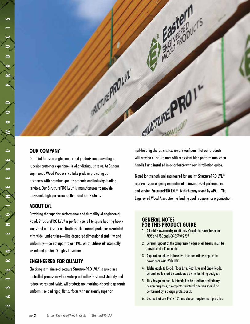
GENERAL NOTES FOR THIS PRODUCT GUIDE1. All tables assume dry conditions. Calculations are based on
NDS and IBC and ICC-ESR#2909.
2. Lateral support of the compression edge of all beams must be provided at 24” on center.
3. Application tables include live load reductions applied in accordance with 2006 IBC.
4. Tables apply to Dead, Floor Live, Roof Live and Snow loads. Lateral loads must be considered by the building designer.
5. This design manual is intended to be used for preliminary design purposes; a complete structural analysis should be performed by a design professional.
6. Beams that are 1¾” x 16” and deeper require multiple plies.
OUR COMPANY Our total focus on engineered wood products and providing a
superior customer experience is what distinguishes us. At Eastern
Engineered Wood Products we take pride in providing our
customers with premium quality products and industry-leading
services. Our StructurePRO LVL® is manufactured to provide
consistent, high performance floor and roof systems.
ABOUT LVL Providing the superior performance and durability of engineered
wood, StructurePRO LVL® is perfectly suited to spans bearing heavy
loads and multi-span applications. The normal problems associated
with wide lumber sizes—like decreased dimensional stability and
uniformity—do not apply to our LVL, which utilizes ultrasonically
tested and graded Douglas fir veneer.
ENGINEERED FOR QUALITY Checking is minimized because StructurePRO LVL® is cured in a
controlled process in which waterproof adhesives boost stability and
reduce warps and twists. All products are machine-ripped to generate
uniform size and rigid, flat surfaces with inherently superior
nail-holding characteristics. We are confident that our products
will provide our customers with consistent high performance when
handled and installed in accordance with our installation guide.
Tested for strength and engineered for quality, StructurePRO LVL®
represents our ongoing commitment to unsurpassed performance
and service. StructurePRO LVL® is third-party tested by APA—The
Engineered Wood Association, a leading quality assurance organization.
page 2 Eastern Engineered Wood Products | StructurePRO LVL®

St
ru
ct
ur
eP
RO
LV
L®
RE
FE
RE
NC
E
DE
SI
GN
V
AL
UE
S
AN
D
BE
AR
IN
G
LE
NG
TH
S
2.0E StructurePRO LVL®
Notes:1. The minimum required bearing length is 1½”.2. Duration of load factors may not be applied to bearing length requirements.3. All StructurePRO LVL® beams require support across their full width.4. All StructurePRO LVL® beams require lateral support at bearing points.
5. The support member must be sized to carry the load from the StructurePRO LVL® beam.6. Use these values when the StructurePRO LVL® beam is supported by a wall plate, sill plate,
timber or built-up girder.
BEARING LENGTH REQUIREMENTSStructurePRO LVL® BEARING LENGTH REQUIREMENTS (1)(2)(3)(4)(5)
Support Material Hem-Fir(6) Southern Pine(6) DF-L(6) 2.0E
StructurePro(6)
Fc (psi) 405 psi 565 psi 625 psi 850 psi
LVL Beam Width 1¾” 3½” 1¾” 3½” 1¾” 3½” 1¾” 3½”
Reac
tion
[lb]
1000 1½” 1½” 1½” 1½” 1½” 1½” 1½” 1½”2000 3” 1½” 2¼” 1½” 2” 1½” 1½” 1½”3000 4¼” 2¼” 3¼” 1¾” 2¾” 1½” 2¼” 1½”4000 5¾” 3” 4¼” 2¼” 3¾” 2” 2¾” 1½”5000 7¼” 3¾” 5¼” 2¾” 4¾” 2½” 3½” 1¾”6000 8½” 4¼” 6¼” 3¼” 5½” 2¾” 4¼” 2¼”7000 10” 5” 7¼” 3¾” 6½” 3¼” 4¾” 2½”8000 5¾” 8¼” 4¼” 7½” 3¾” 5½” 2¾”9000 6½” 9¼” 4¾” 8¼” 4¼” 6¼” 3¼”
10000 7¼” 10¼” 5¼” 9¼” 4¾” 6¾” 3½”11000 8” 11¼” 5¾” 10¼” 5¼” 7½” 3¾”
StructurePRO LVL® BEARING LENGTH REQUIREMENTS (1)(2)(3)(4)(5)
Support Material Hem-Fir(6) Southern Pine(6) DF-L(6) 2.0E
StructurePro(6)
Fc (psi) 405 psi 565 psi 625 psi 850 psi
LVL Beam Width 1¾” 3½” 1¾” 3½” 1¾” 3½” 1¾” 3½”
Reac
tion
[lb]
12000 8½” 6¼” 11” 5½” 8¼” 4¼”13000 9¼” 6¾” 6” 8¾” 4½”14000 10” 7¼” 6½” 9½” 4¾”15000 10¾” 7¾” 7” 10¼” 5¼”16000 8¼” 7½” 11” 5½”17000 8¾” 8” 11½” 5¾”18000 9¼” 8¼” 12¼” 6¼”19000 9¾” 8¾” 13” 6½”20000 10¼” 9¼” 6¾”21000 10¾” 9¾” 7¼”22000 11¼” 10¼” 7½”
Continued in next column
1¾” x 2.0E StructurePRO LVL® REFERENCE DESIGN VALUES
DepthMaximum Vertical Shear
(lb)Maximum Bending
Moment (ft-lb)El
(x 106 lb-in2)
Weight (plf)
100% 115% 125% 100% 115% 125%9¼” 3076 3537 3845 6791 7810 8489 231 4.29½” 3159 3633 3948 7125 8194 8907 250 4.311¼” 3741 4302 4676 9660 11109 12075 415 5.1117⁄8” 3948 4541 4936 10647 12245 13309 488 5.414” 4655 5353 5819 14320 16468 17900 800 6.416” 5320 6118 6650 18210 20942 22763 1195 7.318” 5985 6883 7481 22511 25888 28139 1701 8.220” 6650 7648 8313 27212 31294 34015 2333 9.1237⁄8” 7938 9129 9923 37428 43043 46786 3969 10.9
3½” or TWO-PLY 1¾” x 2.0E StructurePRO LVL® REFERENCE DESIGN VALUES
DepthMaximum Vertical Shear
(lb)Maximum Bending
Moment (ft-lb)El
(x 106 lb-in2)
Weight (plf)
100% 115% 125% 100% 115% 125%9¼” 6151 7074 7689 13583 15620 16978 462 8.49½” 6318 7265 7897 14251 16388 17813 500 8.611¼” 7481 8603 9352 19320 22218 24150 831 10.2117⁄8” 7897 9081 9871 21295 24489 26619 977 10.814” 9310 10707 11638 28639 32935 35799 1601 12.716” 10640 12236 13300 36421 41884 45526 2389 14.518” 11970 13766 14963 45022 51775 56277 3402 16.420” 13300 15295 16625 54424 62587 68030 4667 18.2237⁄8” 15877 18258 19846 74857 86085 93571 7939 21.7
5¼” or THREE-PLY 1¾” x 2.0E StructurePRO LVL® REFERENCE DESIGN VALUES
DepthMaximum Vertical
Shear (lb)Maximum Bending
Moment (ft-lb)El
(x 106 lb-in2)
Weight (plf)
100% 115% 125% 100% 115% 125%3½” 3491 4015 4364 3543 4074 4429 38 4.85½” 5486 6309 6858 7992 9191 9991 146 7.57¼” 7232 8317 9040 13141 15112 16426 333 9.99¼” 9227 10611 11534 20374 23430 25468 693 12.69½” 9476 10898 11845 21376 24582 26720 750 13.011¼” 11222 12905 14027 28980 33327 36225 1246 15.311⅞” 11845 13622 14807 31942 36734 39928 1465 16.214” 13965 16060 17456 42959 49403 53699 2401 19.116” 15960 18354 19950 54631 62826 68289 3584 21.818” 17955 20648 22444 67533 77663 84416 5103 24.520” 19950 22943 24938 81635 93881 102044 7000 27.323⅞” 23815 27388 29769 112285 129128 140357 11908 32.6
7” or FOUR-PLY 1¾” x 2.0E StructurePRO LVL® REFERENCE DESIGN VALUES
DepthMaximum Vertical
Shear (lb)Maximum Bending
Moment (ft-lb)El
(x 106 lb-in2)
Weight (plf)
100% 115% 125% 100% 115% 125%3½” 4655 5353 5819 4724 5432 5905 50 6.45½” 7315 8412 9144 10657 12255 13321 194 10.07¼” 9643 11089 12053 17522 20150 21902 445 13.29¼” 12303 14148 15378 27166 31240 33957 923 16.89½” 12635 14530 15794 28501 32777 35627 1000 17.311¼” 14963 17207 18703 38640 44436 48300 1661 20.511⅞” 15794 18163 19742 42590 48978 53237 1954 21.614” 18620 21413 23275 57279 65871 71599 3201 25.516” 21280 24472 26600 72842 83768 91052 4779 29.118” 23940 27531 29925 90044 103550 112555 6804 32.720” 26600 30590 33250 108847 125174 136059 9333 36.423⅞” 31754 36517 39692 149714 172171 187142 15877 43.4
Equivalent Specific Gravity for Fastener DesignNAILS & WOOD SCREWS: Lateral, face = 0.50 Lateral, edge = 0.50 Withdrawal, face = 0.50 Withdrawal, edge = 0.47
BOLTS & LAG SCREWS:Lateral, face =0.50Lateral, edge = N.A.
2.0E StructurePRO LVL® Reference Design Values(1) Modulus of Elasticity E = 2,000,000 psi(2)
Bending (beam) Fb = 3,100 psi(3)(4)
Horizontal Shear (beam) Fv = 285 psi Compression Perpendicular to Grain (beam) Fc = 850 psi(2)
(1) Values apply to dry service conditions(2) Do not adjust for load duration(3) Adjust by (12/d )1/5, where d is the depth of the member [inches](4) Adjust by 1.04 for repetitive members as defined in the ANSI/AWC NDS
Eastern Engineered Wood Products | www.eewp.com page 3

St
ru
ct
ur
eP
RO
L
VL
®
1
¾”
2
.0
E
FL
OO
R
UN
IF
OR
M
LO
AD
S ALLOWABLE UNIFORM LOADSFLOOR 100% 2.0E BEAM
ALLOWABLE UNIFORM LOADS*– POUNDS PER LINEAL FOOT – 1¾” 2.0E StructurePRO LVL®
Span (ft) Key One 1¾” StructurePRO LVL®
7¼” 9¼” 9½” 11¼” 117⁄8” 14” 16” 18” 20” 237⁄8”
6LL 762 - - - - - - - - -TL 763 1028 1063 1325 1425 1796 2194 2652 3183 4499
BRG 1.5 / 3.9 2.1 / 5.2 2.2 / 5.4 2.7 / 6.7 2.9 / 7.2 3.6 / 9.1 4.4 / 11.1 5.4 / 13.4 6.4 / 16.1 9.1 / 22.7
7LL 480 - - - - - - - - -TL 636 849 877 1083 1161 1445 1742 2074 2446 3317
BRG 1.5 / 3.8 2 / 5 2.1 / 5.2 2.6 / 6.4 2.7 / 6.9 3.4 / 8.5 4.1 / 10.3 4.9 / 12.2 5.8 / 14.4 7.8 / 19.6
8LL 322 668 724 - - - - - - -TL 374 723 746 916 979 1208 1444 1702 1986 2626
BRG 1.5 / 3 2 / 4.9 2 / 5 2.5 / 6.2 2.6 / 6.6 3.3 / 8.2 3.9 / 9.8 4.6 / 11.5 5.4 / 13.4 7.1 / 17.7
9LL 226 469 508 - - - - - - -TL 232 629 649 793 846 1038 1232 1443 1671 2173
BRG 1.5 / 3 1.9 / 4.8 2 / 4.9 2.4 / 6 2.6 / 6.4 3.2 / 7.9 3.8 / 9.4 4.4 / 11 5.1 / 12.7 6.6 / 16.5
10LL - 342 370 615 724 - - - - -TL 151 509 551 699 745 909 1075 1252 1442 1852
BRG 1.5 / 3 1.7 / 4.3 1.9 / 4.7 2.4 / 5.9 2.5 / 6.3 3.1 / 7.7 3.6 / 9.1 4.2 / 10.6 4.9 / 12.2 6.3 / 15.7
11LL - 257 278 462 544 - - - - -TL 102 381 413 625 665 809 953 1105 1268 1614
BRG 1.5 / 3 1.5 / 3.6 1.5 / 3.9 2.3 / 5.8 2.5 / 6.2 3 / 7.5 3.5 / 8.9 4.1 / 10.3 4.7 / 11.8 6 / 15
12LL - 198 214 356 419 686 - - - -TL 71 293 317 529 586 729 855 989 1131 1430
BRG 1.5 / 3 1.5 / 3 1.5 / 3.2 2.2 / 5.4 2.4 / 6 3 / 7.4 3.5 / 8.7 4 / 10.1 4.6 / 11.5 5.8 / 14.5
13LL - 156 169 280 329 540 - - - -TL 51 229 249 415 489 663 776 895 1021 1283
BRG 1.5 / 3 1.5 / 3 1.5 / 3 1.8 / 4.6 2.2 / 5.4 2.9 / 7.3 3.4 / 8.6 3.9 / 9.9 4.5 / 11.2 5.7 / 14.1
14LL - 125 135 224 264 432 645 - - -TL 37 183 198 331 390 578 710 817 930 1163
BRG 1.5 / 3 1.5 / 3 1.5 / 3 1.6 / 4 1.9 / 4.7 2.8 / 6.9 3.4 / 8.4 3.9 / 9.7 4.4 / 11 5.5 / 13.8
15LL 101 110 182 214 351 524 747 - -TL 148 160 268 316 503 640 752 854 1064
BRG 1.5 / 3 1.5 / 3 1.5 / 3.4 1.6 / 4.1 2.6 / 6.4 3.3 / 8.2 3.8 / 9.6 4.3 / 10.9 5.4 / 13.5
16LL 83 90 150 177 289 432 615 - -TL 121 131 220 260 428 562 695 789 980
BRG 1.5 / 3 1.5 / 3 1.5 / 3 1.5 / 3.6 2.3 / 5.8 3.1 / 7.7 3.8 / 9.5 4.3 / 10.7 5.3 / 13.3
17LL 70 75 125 147 241 360 513 704 -TL 100 109 183 216 356 497 615 733 908
BRG 1.5 / 3 1.5 / 3 1.5 / 3 1.5 / 3.2 2.1 / 5.2 2.9 / 7.2 3.6 / 8.9 4.2 / 10.6 5.3 / 13.1
18LL 59 64 105 124 203 303 432 593 -TL 84 91 153 181 299 442 548 663 846
BRG 1.5 / 3 1.5 / 3 1.5 / 3 1.5 / 3 1.8 / 4.6 2.7 / 6.8 3.4 / 8.4 4.1 / 10.2 5.2 / 13
19LL 54 90 105 173 258 367 504 -TL 77 129 153 253 380 491 594 792
BRG 1.5 / 3 1.5 / 3 1.5 / 3 1.7 / 4.1 2.5 / 6.2 3.2 / 8 3.9 / 9.6 5.1 / 12.8
20LL 77 90 148 221 315 432 735TL 110 130 216 325 442 535 738
BRG 1.5 / 3 1.5 / 3 1.5 / 3.7 2.2 / 5.6 3 / 7.6 3.7 / 9.1 5 / 12.6
21LL 66 78 128 191 272 373 635TL 95 112 186 279 400 485 668
BRG 1.5 / 3 1.5 / 3 1.5 / 3.4 2 / 5.1 2.9 / 7.2 3.5 / 8.7 4.8 / 12
22LL 58 68 111 166 237 325 552TL 82 97 161 242 347 441 608
BRG 1.5 / 3 1.5 / 3 1.5 / 3.1 1.8 / 4.6 2.6 / 6.6 3.3 / 8.3 4.6 / 11.4
23LL 59 97 145 207 284 483TL 84 140 211 302 402 555
BRG 1.5 / 3 1.5 / 3 1.7 / 4.2 2.4 / 6 3.2 / 8 4.4 / 10.9
24LL 86 128 182 250 425TL 122 185 265 366 509
BRG 1.5 / 3 1.5 / 3.9 2.2 / 5.5 3 / 7.6 4.2 / 10.5
25LL 76 113 161 221 376TL 107 163 234 323 468
BRG 1.5 / 3 1.5 / 3.6 2 / 5.1 2.8 / 7 4 / 10.1
26LL 67 101 143 197 335TL 95 144 207 286 432
BRG 1.5 / 3 1.5 / 3.3 1.9 / 4.7 2.6 / 6.4 3.9 / 9.7
27LL 60 90 128 176 299TL 84 128 184 254 400
BRG 1.5 / 3 1.5 / 3.1 1.7 / 4.4 2.4 / 6 3.7 / 9.3
28LL 54 81 115 157 268TL 75 114 164 227 371
BRG 1.5 / 3 1.5 / 3 1.6 / 4.1 2.2 / 5.6 3.6 / 9
29LL 73 103 142 241TL 102 147 204 345
BRG 1.5 / 3 1.5 / 3.8 2.1 / 5.2 3.5 / 8.7
30LL 66 93 128 218TL 91 132 183 316
BRG 1.5 / 3 1.5 / 3.5 1.9 / 4.8 3.3 / 8.2Key to Table: LL = Maximum live load – limits deflection to L/360 TL = Maximum total load – limits deflection to L/240
(or a maximum of 0 .3125’’ for beams 7.25’’ deep or less) BRG = Required end / intermediate bearing length [inches], based on bearing stress of 850 psiUse sizing software or consult a professional engineer to analyze conditions outside the scope of this table (e.g. concentrated loads) or for multiple span beams if the length of any span is less than half the length of an adjacent span
Notes: 1. Table is based on 1¾” width. PLF values may be multiplied by 2 for 3½” width, 3 for 5¼”, and 4 for 7”. 2. Simple or multiple spans measured center to center of supports3. Table values account for beam weight4. Provide lateral restraint at supports and every 24 inches or less along the compression edge (CL = 1)5. 4 plies maximum6. 2 plies minimum for depths greater than 14 inches7. No camber
page 4 Eastern Engineered Wood Products | StructurePRO LVL®

ALLOWABLE UNIFORM LOADS ROOF SNOW 115% 2.0E
St
ru
ct
ur
eP
RO
LV
L®
1¾
”
2.
0E
R
OO
F
UN
IF
OR
M
LO
AD
S
ALLOWABLE UNIFORM LOADS* – POUNDS PER LINEAL FOOT – 1¾” 2.0E StructurePRO LVL®
Span (ft) Key One 1¾” StructurePRO LVL®
7¼” 9¼” 9½” 11¼” 117⁄8” 14” 16” 18” 20” 237⁄8”
6LL - - - - - - - - - -TL 878 1183 1224 1524 1640 2066 2524 3051 3662 5175
BRG 1.8 / 4.4 2.4 / 6 2.5 / 6.2 3.1 / 7.7 3.3 / 8.3 4.2 / 10.4 5.1 / 12.8 6.2 / 15.4 7.4 / 18.5 10.5 / 26.1
7LL - - - - - - - - - -TL 640 977 1009 1246 1336 1662 2004 2386 2815 3816
BRG 1.5 / 3.8 2.3 / 5.8 2.4 / 6 2.9 / 7.4 3.2 / 7.9 3.9 / 9.8 4.7 / 11.8 5.6 / 14.1 6.6 / 16.6 9 / 22.5
8LL - - - - - - - - - -TL 374 832 859 1054 1127 1390 1661 1958 2285 3022
BRG 1.5 / 3 2.2 / 5.6 2.3 / 5.8 2.8 / 7.1 3 / 7.6 3.8 / 9.4 4.5 / 11.2 5.3 / 13.2 6.2 / 15.4 8.2 / 20.4
9LL - 704 - - - - - - - -TL 232 724 747 913 974 1194 1418 1660 1923 2500
BRG 1.5 / 3 2.2 / 5.5 2.3 / 5.7 2.8 / 6.9 3 / 7.4 3.6 / 9.1 4.3 / 10.8 5 / 12.6 5.8 / 14.6 7.6 / 19
10LL - 513 556 - - - - - - -TL 151 621 651 805 858 1047 1237 1441 1659 2132
BRG 1.5 / 3 2.1 / 5.3 2.2 / 5.5 2.7 / 6.8 2.9 / 7.3 3.5 / 8.8 4.2 / 10.5 4.9 / 12.2 5.6 / 14 7.2 / 18
11LL - 385 418 693 - - - - - -TL 102 510 537 719 766 931 1097 1272 1459 1858
BRG 1.5 / 3 1.9 / 4.8 2 / 5 2.7 / 6.7 2.9 / 7.1 3.5 / 8.7 4.1 / 10.2 4.7 / 11.8 5.4 / 13.6 6.9 / 17.3
12LL - 297 322 534 628 - - - - -TL 71 392 424 612 675 839 985 1139 1302 1646
BRG 1.5 / 3 1.6 / 4 1.7 / 4.3 2.5 / 6.2 2.7 / 6.9 3.4 / 8.5 4 / 10 4.6 / 11.6 5.3 / 13.2 6.7 / 16.7
13LL - 233 253 420 494 - - - - -TL 51 307 333 521 574 763 894 1031 1175 1477
BRG 1.5 / 3 1.5 / 3.4 1.5 / 3.7 2.3 / 5.7 2.5 / 6.3 3.4 / 8.4 3.9 / 9.8 4.5 / 11.3 5.2 / 12.9 6.5 / 16.3
14LL - 187 203 336 396 648 - - - -TL 37 245 266 443 494 666 818 941 1071 1340
BRG 1.5 / 3 1.5 / 3 1.5 / 3.2 2.1 / 5.3 2.4 / 5.9 3.2 / 7.9 3.9 / 9.7 4.5 / 11.2 5.1 / 12.7 6.4 / 15.9
15LL 152 165 273 322 527 - - - -TL 198 215 359 423 579 737 866 983 1225
BRG 1.5 / 3 1.5 / 3 1.8 / 4.6 2.2 / 5.4 3 / 7.4 3.8 / 9.4 4.4 / 11 5 / 12.5 6.2 / 15.6
16LL 125 136 225 265 434 - - - -TL 163 177 295 348 508 647 801 909 1129
BRG 1.5 / 3 1.5 / 3 1.6 / 4 1.9 / 4.8 2.8 / 6.9 3.5 / 8.8 4.4 / 10.9 4.9 / 12.3 6.1 / 15.3
17LL 104 113 188 221 362 540 - - -TL 135 146 245 289 449 572 708 845 1046
BRG 1.5 / 3 1.5 / 3 1.5 / 3.6 1.7 / 4.2 2.6 / 6.5 3.3 / 8.3 4.1 / 10.2 4.9 / 12.2 6 / 15.1
18LL 88 95 158 186 305 455 - - -TL 113 123 206 243 400 510 631 764 975
BRG 1.5 / 3 1.5 / 3 1.5 / 3.2 1.5 / 3.8 2.5 / 6.2 3.1 / 7.8 3.9 / 9.7 4.7 / 11.7 6 / 14.9
19LL 81 135 158 259 387 551 - -TL 104 174 206 339 457 566 684 913
BRG 1.5 / 3 1.5 / 3 1.5 / 3.4 2.2 / 5.5 3 / 7.4 3.7 / 9.2 4.4 / 11.1 5.9 / 14.7
20LL 115 136 222 332 473 - -TL 149 175 290 412 510 617 850
BRG 1.5 / 3 1.5 / 3 2 / 5 2.8 / 7 3.5 / 8.7 4.2 / 10.5 5.8 / 14.5
21LL 100 117 192 287 408 - -TL 128 151 250 373 461 559 770
BRG 1.5 / 3 1.5 / 3 1.8 / 4.5 2.7 / 6.7 3.3 / 8.3 4 / 10 5.5 / 13.8
22LL 87 102 167 249 355 487 -TL 110 131 216 325 420 508 701
BRG 1.5 / 3 1.5 / 3 1.6 / 4.1 2.5 / 6.1 3.2 / 7.9 3.8 / 9.6 5.3 / 13.2
23LL 89 146 218 311 426 -TL 114 189 284 383 464 640
BRG 1.5 / 3 1.5 / 3.8 2.2 / 5.6 3 / 7.6 3.7 / 9.1 5 / 12.6
24LL 129 192 273 375 -TL 165 249 351 426 587
BRG 1.5 / 3.5 2.1 / 5.2 2.9 / 7.3 3.5 / 8.8 4.8 / 12.1
25LL 114 170 242 332 -TL 145 219 314 391 540
BRG 1.5 / 3.2 1.9 / 4.8 2.7 / 6.8 3.4 / 8.4 4.6 / 11.6
26LL 101 151 215 295 -TL 129 194 279 361 499
BRG 1.5 / 3 1.8 / 4.4 2.5 / 6.3 3.2 / 8.1 4.5 / 11.1
27LL 90 135 192 263 448TL 114 173 248 334 461
BRG 1.5 / 3 1.6 / 4.1 2.3 / 5.8 3.1 / 7.8 4.3 / 10.7
28LL 81 121 172 236 402TL 102 154 221 306 428
BRG 1.5 / 3 1.5 / 3.8 2.2 / 5.4 3 / 7.4 4.1 / 10.3
29LL 109 155 213 362TL 138 198 274 399
BRG 1.5 / 3.5 2 / 5 2.8 / 6.9 4 / 10
30LL 98 140 192 327TL 124 178 247 372
BRG 1.5 / 3.3 1.9 / 4.7 2.6 / 6.5 3.9 / 9.6Key to Table: LL = Maximum live load – limits deflection to L/360 TL = Maximum total load – limits deflection to L/240
(or a maximum of 0 .3125’’ for beams 7.25’’ deep or less) BRG = Required end / intermediate bearing length [inches], based on bearing stress of 850 psiUse sizing software or consult a professional engineer to analyze conditions outside the scope of this table (e.g. concentrated loads) or for multiple span beams if the length of any span is less than half the length of an adjacent span
Notes: 1. Table is based on 1¾” width. PLF values may be multiplied by 2 for 3½” width, 3 for 5¼”, and 4 for 7”. 2. Simple or multiple spans measured center to center of supports3. Table values account for beam weight4. Provide lateral restraint at supports and every 24 inches or less along the compression edge (CL = 1)5. 4 plies maximum6. 2 plies minimum for depths greater than 14 inches7. No camber
Eastern Engineered Wood Products | www.eewp.com page 5

For multiple-ply StructurePRO LVL® beam assembly conditions and fastening recommendations, see next page.
WINDOW/DOOR HEADER— 2-STORY TYPICAL
See “Bearing Length Requirements” on page 3.
B6BEARING FOR DOOR OR WINDOW HEADER—1-STORY TYPICAL
See “Bearing Length Requirements” on page 3.
B5
BEARING DETAILSB1 BEAM-TO-BEAM CONNECTION
Make sure hanger capacity is appropriate for each application. Hangers must be properly installed to accommodate full capacity.
B2 BEARING ON WOOD COLUMN
Verify the required bearing area and the ability of the supporting column member to provide adequate strength.
B3 BEARING ON STEEL COLUMN
Verify the required bearing area and the ability of the supporting column member to provide adequate strength.
B4 BEARING ON EXTERIOR WALL
Prevent direct contact of StructurePRO LVL® with concrete. Consult local building code for requirements.
St
ru
ct
ur
eP
RO
L
VL
®
B
EA
RI
NG
D
ET
AI
LS
page 6 Eastern Engineered Wood Products | StructurePRO LVL®
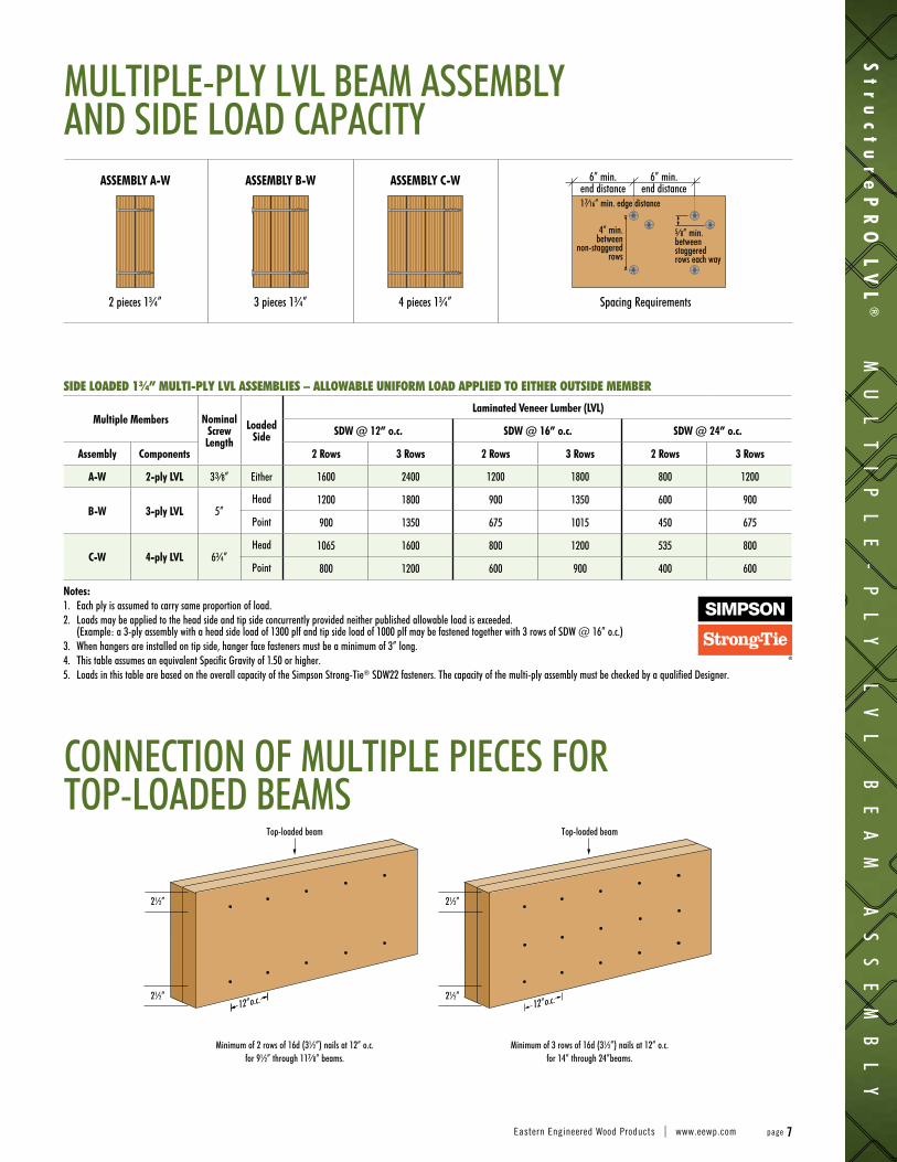
SIDE LOADED 1¾” MULTI-PLY LVL ASSEMBLIES – ALLOWABLE UNIFORM LOAD APPLIED TO EITHER OUTSIDE MEMBER
Multiple Members Nominal Screw Length
Loaded Side
Laminated Veneer Lumber (LVL)
SDW @ 12” o.c. SDW @ 16” o.c. SDW @ 24” o.c.
Assembly Components 2 Rows 3 Rows 2 Rows 3 Rows 2 Rows 3 Rows
A-W 2-ply LVL 33⁄8” Either 1600 2400 1200 1800 800 1200
B-W 3-ply LVL 5”Head 1200 1800 900 1350 600 900
Point 900 1350 675 1015 450 675
C-W 4-ply LVL 6¾”Head 1065 1600 800 1200 535 800
Point 800 1200 600 900 400 600
Notes: 1. Each ply is assumed to carry same proportion of load.2. Loads may be applied to the head side and tip side concurrently provided neither published allowable load is exceeded.
(Example: a 3-ply assembly with a head side load of 1300 plf and tip side load of 1000 plf may be fastened together with 3 rows of SDW @ 16” o.c.)3. When hangers are installed on tip side, hanger face fasteners must be a minimum of 3” long.4. This table assumes an equivalent Specific Gravity of 1.50 or higher.5. Loads in this table are based on the overall capacity of the Simpson Strong-Tie® SDW22 fasteners. The capacity of the multi-ply assembly must be checked by a qualified Designer.
MULTIPLE-PLY LVL BEAM ASSEMBLY AND SIDE LOAD CAPACITY
CONNECTION OF MULTIPLE PIECES FOR TOP-LOADED BEAMS
ASSEMBLY A-W
2 pieces 1¾”
ASSEMBLY B-W
3 pieces 1¾”
ASSEMBLY C-W
4 pieces 1¾” Spacing Requirements
6” min.end distance17⁄16” min. edge distance
5⁄8” min. between staggered rows each way
Minimum of 2 rows of 16d (3½”) nails at 12” o.c. for 9½” through 117⁄8” beams.
Minimum of 3 rows of 16d (3½”) nails at 12” o.c. for 14” through 24”beams.
Top-loaded beam
12” o.c. 12” o.c.
2½” 2½”
2½” 2½”
Top-loaded beam
4” min. between
non-staggered rows
6” min.end distance
St
ru
ct
ur
eP
RO
LV
L®
MU
LT
IP
LE
-P
LY
L
VL
B
EA
M
AS
SE
MB
LY
Eastern Engineered Wood Products | www.eewp.com page 7

HOLE DETAILS IN StructurePRO LVL® BEAMSSee note 4
¼ span 1⁄3 span
End support Interior support
1⁄3 depth
1⁄3 depth
1⁄3 depth
Notes:1. This detail applies only to uniformly loaded, simple and multiple span beams. Cantilevered
beams and beams that carry concentrated loads are outside the scope of this detail.2. Square and rectangular holes are not permitted.3. Round holes may be drilled or cut with a hole saw anywhere within the shaded area of
the beam.4. The horizontal distance between adjacent holes must be at least two times the size of the
larger hole. This restriction also applies to the location of access holes relative to bolt holes in multi-ply beams.
5. Do not drill more than three access holes in any four foot long section of beam.
6. The maximum round hole diameter permitted is:
LVL Beam Depth 5½” 7¼” 9½” to 24”Maximum Hole Diameter 11⁄8” 1½” 2”
7. These limitations apply to holes drilled for plumbing or wiring access only. The size and location of holes drilled for fasteners are governed by the provisions of the National Design Specification® for Wood Construction.
8. Beams deflect under load. Size holes to provide clearance where required.9. Larger holes may be permissible. Please consult your design software or call for
engineering support.
St
ru
ct
ur
eP
RO
L
VL
®
H
OL
E
DE
TA
IL
S
page 8 Eastern Engineered Wood Products | StructurePRO LVL®
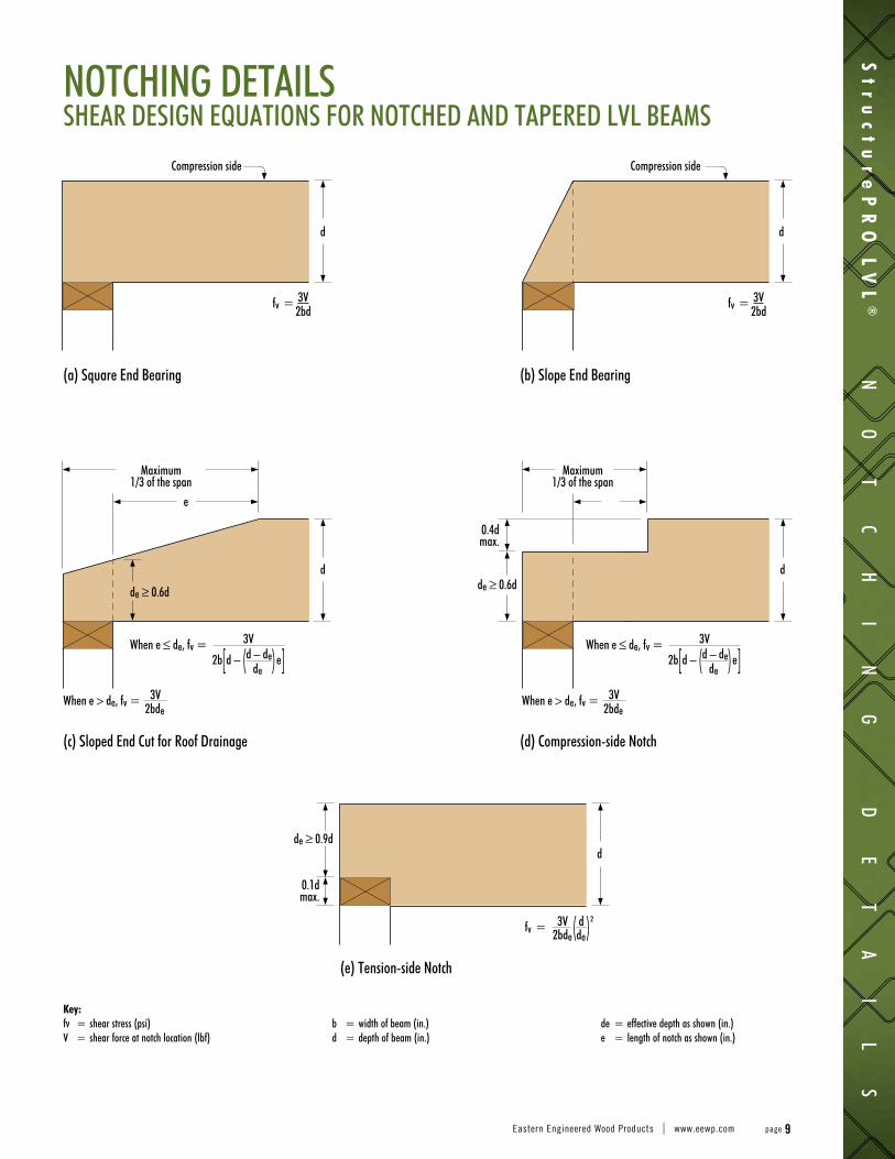
NOTCHING DETAILSSHEAR DESIGN EQUATIONS FOR NOTCHED AND TAPERED LVL BEAMS
Key:fv = shear stress (psi) V = shear force at notch location (lbf)
b = width of beam (in.)d = depth of beam (in.)
de = effective depth as shown (in.) e = length of notch as shown (in.)
Compression side
Maximum 1/3 of the span
When e ≤ de, fv = 3V
2b[d – (d – de)e] de
fv = 3V ( d )2
2bde de
When e ≤ de, fv = 3V
2b[d – (d – de)e] de
When e > de, fv = 3V
2bdeWhen e > de, fv = 3V
2bde
e
de ≥ 0.6d
de ≥ 0.9d
de ≥ 0.6d
0.4d max.
0.1d max.
Maximum 1/3 of the span
fv = 3V 2bd
fv = 3V 2bd
Compression side
d
d d
d
d
(a) Square End Bearing
(c) Sloped End Cut for Roof Drainage
(e) Tension-side Notch
(b) Slope End Bearing
(d) Compression-side Notch
St
ru
ct
ur
eP
RO
LV
L®
NO
TC
HI
NG
D
ET
AI
LS
Eastern Engineered Wood Products | www.eewp.com page 9
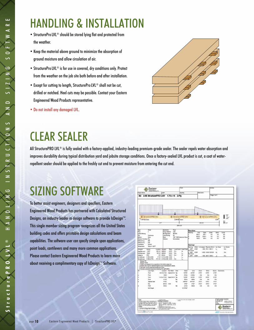
HANDLING & INSTALLATION
SIZING SOFTWARETo better assist engineers, designers and specifiers, Eastern
Engineered Wood Products has partnered with Calculated Structured
Designs, an industry leader in design software to provide IsDesign™.
This single member sizing program recognizes all the United States
building codes and offers printable design calculations and beam
capabilities. The software user can specify simple span applications,
point loads, cantilevers and many more common applications.
Please contact Eastern Engineered Wood Products to learn more
about receiving a complimentary copy of IsDesign™ Software.
CLEAR SEALERAll StructurePRO LVL® is fully sealed with a factory-applied, industry-leading premium-grade sealer. The sealer repels water absorption and
improves durability during typical distribution yard and jobsite storage conditions. Once a factory-sealed LVL product is cut, a coat of water-
repellent sealer should be applied to the freshly cut end to prevent moisture from entering the cut end.
• StructurePro LVL® should be stored lying flat and protected from
the weather.
• Keep the material above ground to minimize the absorption of
ground moisture and allow circulation of air.
• StructurePro LVL® is for use in covered, dry conditions only. Protect
from the weather on the job site both before and after installation.
• Except for cutting to length, StructurePro LVL® shall not be cut,
drilled or notched. Heel cuts may be possible. Contact your Eastern
Engineered Wood Products representative.
• Do not install any damaged LVL.
St
ru
ct
ur
eP
RO
L
VL
®
H
AN
DL
IN
G
IN
ST
RU
CT
IO
NS
A
ND
S
IZ
IN
G
SO
FT
WA
RE
page 10 Eastern Engineered Wood Products | StructurePRO LVL®
TECHNICAL SUPPORTWhile supplying a superior product, we are also
dedicated to an unprecedented level of support
to our customers. We provide not only phone
support, but a broad library of technical materials,
bulletins and other relevant information for our
products. Our highly trained technical services staff,
led by industry veterans, combine their extensive
knowledge and state-of-the-art tools to assist
you with any design or construction question and
provide full support for our design software.
TECHNICAL CERTIFICATIONSOur product is manufactured to the highest
industry standards, and is backed by Evaluation
Reports produced by third-party testing and
certification bodies.
St
ru
ct
ur
eP
RO
LV
L®
TE
CH
NI
CA
L
SU
PP
OR
T
AN
D
CE
RT
IF
IC
AT
IO
NS
Eastern Engineered Wood Products | www.eewp.com page 11
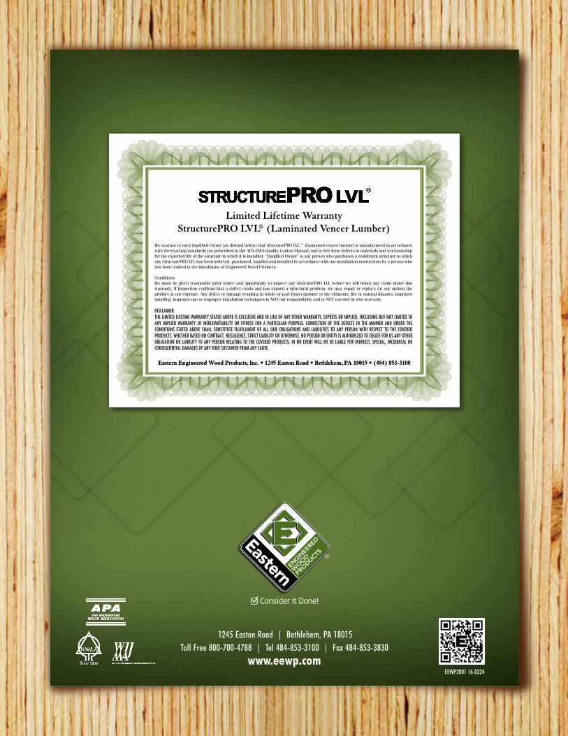
We warrant to each Qualified Owner (as defined below) that StructurePRO LVL™ (laminated veneer lumber) is manufactured in accordance with the exacting standards (as prescribed in the APA-EWS Quality Control Manual) and is free from defects in materials and workmanship for the expected life of the structure in which it is installed. “Qualified Owner” is any person who purchases a residential structure in which any StructurePRO LVL has been selected, purchased, handled and installed in accordance with our installation instructions by a person who has been trained in the installation of Engineered Wood Products.
Conditions: We must be given reasonable prior notice and opportunity to inspect any StructurePRO LVL before we will honor any claim under this warranty. If inspection confirms that a defect exists and has caused a structural problem, we may repair or replace (at our option) the product at our expense. Any defect or damage resulting in whole or part from exposure to the elements, fire or natural disaster, improper handling, improper use or improper installation techniques is NOT our responsibility and is NOT covered by this warranty.
DISCLAIMER:THE LIMITED LIFETIME WARRANTY STATED ABOVE IS EXCLUSIVE AND IN LIEU OF ANY OTHER WARRANTY, EXPRESS OR IMPLIED, INCLUDING BUT NOT LIMITED TO ANY IMPLIED WARRANTY OF MERCHANTABILITY OR FITNESS FOR A PARTICULAR PURPOSE. CORRECTION OF THE DEFECTS IN THE MANNER AND UNDER THE CONDITIONS STATED ABOVE SHALL CONSTITUTE FULFILLMENT OF ALL OUR OBLIGATIONS AND LIABILITIES TO ANY PERSON WITH RESPECT TO THE COVERED PRODUCTS, WHETHER BASED ON CONTRACT, NEGLIGENCE, STRICT LIABILITY OR OTHERWISE. NO PERSON OR ENTITY IS AUTHORIZED TO CREATE FOR US ANY OTHER OBLIGATION OR LIABILITY TO ANY PERSON RELATING TO THE COVERED PRODUCTS. IN NO EVENT WILL WE BE LIABLE FOR INDIRECT, SPECIAL, INCIDENTAL OR CONSEQUENTIAL DAMAGES OF ANY KIND SUSTAINED FROM ANY CAUSE.
Eastern Engineered Wood Products, Inc. • 1245 Easton Road • Bethlehem, PA 18015 • (484) 853-3100Eastern Engineered Wood Products, Inc. • 1245 Easton Road • Bethlehem, PA 18015 • (484) 853-3100
Limited Lifetime WarrantyStructurePRO LVL® (Laminated Veneer Lumber)
1245 Easton Road | Bethlehem, PA 18015Toll Free 800-700-4788 | Tel 484-853-3100 | Fax 484-853-3830
www.eewp.comEEWP2001 16-0324