Technical data - Dematek AB · Demag chain hoist, 2-steps Manulift, 2-steps Chain hoist stepless...
24
Technical data Demag DC-Com 1 to DC-Com 10 chain hoists 42647546.jpg 290808 enGB 203 571 44 714 IS 817
Transcript of Technical data - Dematek AB · Demag chain hoist, 2-steps Manulift, 2-steps Chain hoist stepless...

Technical dataDemag DC-Com 1 to DC-Com 10 chain hoists
42647546.jpg
290808 enGB 203 571 44 714 IS 817
2 2035
7144
.indd
/290
808
6 5 7 8 9 14
10 11
1 2 4 3
12
17
18
16
15
13
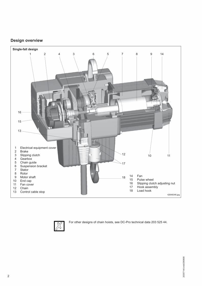
Design overview
42648346.jpg
1 Electrical equipment cover 2 Brake 3 Slipping clutch 4 Gearbox 5 Chain guide 6 Suspension bracket 7 Stator 8 Rotor 9 Motor shaft 10 End cap 11 Fan cover 12 Chain 13 Control cable stop
14 Fan15 Pulse wheel16 Slipping clutch adjusting nut17 Hook assembly18 Load hook
Single-fall design
For other designs of chain hoists, see DC-Pro technical data 203 525 44.
32035
7144
.indd
/290
808
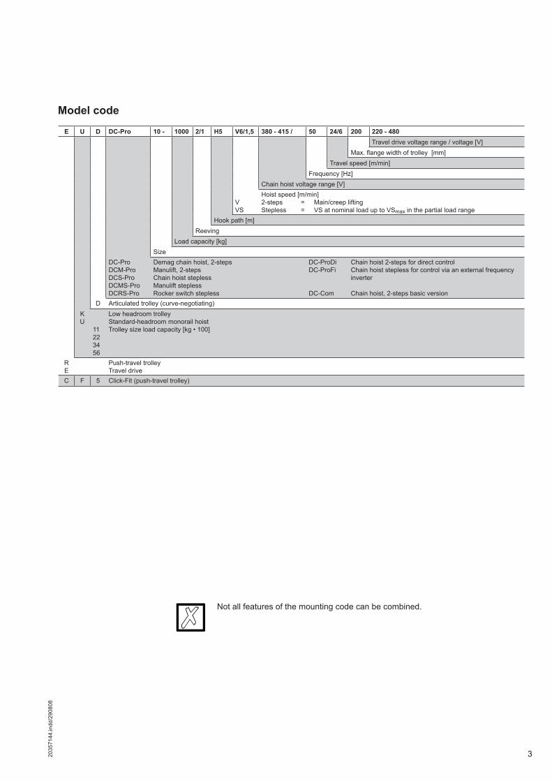
Model code
E U D DC-Pro 10 - 1000 2/1 H5 V6/1,5 380 - 415 / 50 24/6 200 220 - 480Travel drive voltage range / voltage [V]
Max. fl ange width of trolley [mm]Travel speed [m/min]
Frequency [Hz]Chain hoist voltage range [V]
VVS
Hoist speed [m/min]2-steps = Main/creep liftingStepless = VS at nominal load up to VSmax in the partial load range
Hook path [m]Reeving
Load capacity [kg]Size
DC-ProDCM-ProDCS-ProDCMS-ProDCRS-Pro
Demag chain hoist, 2-stepsManulift, 2-stepsChain hoist steplessManulift steplessRocker switch stepless
DC-ProDiDC-ProFi
DC-Com
Chain hoist 2-steps for direct controlChain hoist stepless for control via an external frequency inverter
Chain hoist, 2-steps basic versionD Articulated trolley (curve-negotiating)
KU
11223456
Low headroom trolleyStandard-headroom monorail hoistTrolley size load capacity [kg • 100]
RE
Push-travel trolleyTravel drive
C F 5 Click-Fit (push-travel trolley)
Not all features of the mounting code can be combined.

4 2035
7144
.indd
/290
808
Selection criteria
For the medium load spectrum and an average daily operating time of 1,8 hours, the table shows group 1Am. For the load capacity of 250 kg, the diagram shows size DC-Com 2–250.
The load spectrum(in most cases estimated) can be evaluated in accordance with the following defi nitions:L1 LightHoist units which are usually subject to very small loads and in exceptional cases only to maximum loads.L2 MediumHoist units which are usually subject to small loads but rather often to maximum loads.L3 HeavyHoist units which are usually subject to medium loads but frequently to maximum loads.L4 Very heavyHoist units which are usually subject to maximum or almost maximum loads.
The size of the hoist is determined by the load spectrum, average operating time per working day, SWL and reeving.1. What are the operating conditions?2. What is the specifi ed safe working load?3. To what height must the load be lifted?4. What is the required lifting speed?5. Do the loads need to be lifted and lowered with high precision?6. Is horizontal load travel necessary?7. How is the hoist to be controlled?
Example: Load capacity 250 kg “Medium” load spectrum from tableHoist speed 4 m/min 1/1 reevingAverage hook path 3 m No. of cycles/h 9 Working time/day 8 h
The average operating time per working day is estimated or calculated as follows:
The chain hoist group of mechanisms is determined by the load spectrum and operating time.Load spectrum Average operating time per working day in hoursL1 Light 2-4 4-8 8-16 over 16L2 Medium 1-2 2-4 4-8 8-16L3 Heavy 0,5-1 1-2 2-4 4-8L4 Very heavy 0,25-0,5 0,5-1 1-2 2-4Group of mechanisms to FEM 1Am 2m 3m 4mReeving arrangement Range Size1/1 2/1SWL in kg
Demag DC chain hoist80 DC-Com 1 80100 DC-Com 1 100125 DC-Com 1 125160 DC-Com 2 160200 DC-Com 2 200250 DC-Com 2 250315 DC-Com 5 315400 DC-Com 5 400500 DC-Com 5 500630 DC-Com 10 630800 DC-Com 10 8001000 DC-Com 10 1000
1250 DC-Com 10 12501600 DC-Com 10 16002000 DC-Com 10 2000
Operating time/day =
2 x average hook path x no. of cycles/h. x working time/day=
60 x hoist speed
2 x 3 x 9 x 8= 1,8 hours
60 x 442699344.eps
m = SWLt = Operating timea = Full loadb = Medium partial loadc = Small to medium partial loadd = Small dead loade = Small to medium dead loadf = Heavy dead loadg = Very heavy dead load
52035
7144
.indd
/290
808
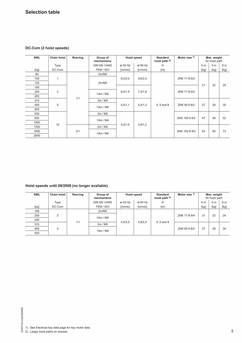
Selection table
SWL Chain hoist Reeving Group of mechanisms
Hoist speed Standardhook path 2)
Motor size 1) Max. weightfor hook path
Type DIN EN 14492 at 50 Hz at 60 Hz H 4 m 5 m 8 m[kg] DC-Com FEM / ISO [m/min] [m/min] [m] [kg] [kg] [kg]80
1
1/1
3m/M68,0/2,0 9,6/2,4
4, 5 and 8
ZNK 71 B 8/2
21 22 24
1002m/M5125
1602 6,0/1,5 7,2/1,8 ZNK 71 B 8/2200
1Am / M4250315
52m / M5
4,5/1,1 5,4/1,3 ZNK 80 A 8/2 27 28 304001Am / M4
500630
10
2m / M5
4,0/1,0 4,8/1,2
ZNK 100 A 8/2 47 48 528001Am / M4
10001250
2/12m / M5
ZNK 100 B 8/2 63 65 7316001Am / M4
2000
1) See Electrical key data page for key motor data.2) Larger hook paths on request.
DC-Com (2 hoist speeds)
SWL Chain hoist Reeving Group of mechanisms
Hoist speed Standardhook path 2)
Motor size 1) Max. weightfor hook path
Type DIN EN 14492 at 50 Hz at 60 Hz H 4 m 5 m 8 m[kg] DC-Com FEM / ISO [m/min] [m/min] [m] [kg] [kg] [kg]160
2
1/1
2m/M5
4,0/2,0 4,8/2,4 4, 5 and 8
ZNK 71 B 8/4 21 22 242001Am / M4
250315
52m / M5
ZNK 80 A 8/4 27 28 304001Am / M4
500
Hoist speeds until 09/2008 (no longer available)

6 2035
7144
.indd
/290
808
1) Imax = maximum rated current for lowering operation.
Size Motor size No. of poles
Min. / max. currents and starting current220-240 V, 60 Hz, 3 ~ (CSA) 380-400 V, 60 Hz, 3 ~ (CE)
PN CDF nN Starts/h IN 220 IN 240 Imax 1) IA/IN 240 cos ϕN IN 380 IN 400 Imax 1) IA/IN 400 cos ϕN
DC-Com [kW] [%] [rpm] [A] [A] [A] [A] [A] [A]
1 ZNK 71 B 8/28 0,06 20 870 240 2,10 2,50 2,50 1,45 0,47 1,35 1,60 1,60 1,45 0,472 0,22 40 3525 120 2,50 3,35 3,35 2,75 0,45 1,70 2,00 2,00 2,75 0,45
2 ZNK 71 B 8/28 0,09 15 845 240 2,10 2,50 2,80 1,45 0,51 1,40 1,60 1,70 1,45 0,512 0,36 25 3480 120 2,70 3,30 3,85 2,75 0,54 1,80 2,00 2,20 2,75 0,54
5 ZNK 80 A 8/28 0,12 15 870 240 2,30 2,30 2,60 2,50 0,45 1,55 1,55 1,75 2,50 0,452 0,49 25 3510 120 4,40 5,60 6,60 4,70 0,48 3,00 3,50 4,10 4,70 0,48
10ZNK 100 A 8/2
8 0,23 15 855 240 3,35 3,75 4,40 1,90 0,47 2,30 2,50 2,80 1,90 0,472 0,90 25 3450 120 4,20 4,80 5,40 4,85 0,67 2,70 2,90 3,30 4,85 0,64
ZNK 100 B 8/2 8 0,44 15 885 240
-5,75 6,40 7,10 2,30 0,41
2 1,80 25 3555 120 7,30 8,90 10,00 5,10 0,48
Hoist motor data (The tolerance of the voltage range must not exceed ± 10 %.)The motors are designed in compliance with insulation class F.
Size Motor size No. of poles
Min. / max. currents and starting current220-240 V, 50 Hz, 3 ~ (CE) 380-415 V, 50 Hz, 3 ~ (CE)
PN CDF nN Starts/h IN 220 IN 240 Imax 1) IA/IN 240 cos ϕN IN 380 IN 415 Imax 1) IA/IN 415 cos ϕN
DC-Com [kW] [%] [rpm] [A] [A] [A] [A] [A] [A]
1 ZNK 71 B 8/28 0,05 20 720 240 1,75 2,10 2,10 1,45 0,48 1,00 1,20 1,20 1,45 0,482 0,18 40 2950 120 2,10 2,80 2,80 2,75 0,46 1,20 1,60 1,60 2,75 0,46
2 ZNK 71 B 8/28 0,07 15 695 240 1,80 2,10 2,35 1,45 0,52 1,00 1,20 1,35 1,45 0,522 0,30 25 2880 120 2,30 2,80 3,20 2,75 0,55 1,30 1,60 1,85 2,75 0,55
5 ZNK 80 A 8/28 0,10 15 720 240 1,90 1,90 2,15 2,50 0,46 1,10 1,10 1,25 2,50 0,462 0,41 25 2910 120 3,60 4,70 5,50 4,70 0,49 2,10 2,70 3,20 4,70 0,49
10ZNK 100 A 8/2
8 0,19 15 705 240 2,80 3,10 3,65 1,90 0,48 1,60 1,80 2,10 1,90 0,482 0,75 25 2850 120 3,50 4,00 4,50 4,85 0,65 2,00 2,30 2,60 4,85 0,65
ZNK 100 B 8/2 8 0,37 15 735 240
-3,90 4,60 5,40 2,30 0,42
2 1,50 25 2955 120 5,40 6,30 7,70 5,10 0,49
Size Motor size No. of poles
Min. / max. currents and starting current500-525 V, 50 Hz, 3 ~ (CE/CSA)
PN CDF nN Starts/h IN 500 IN 525 Imax 1) IA/IN 525 cos ϕN
DC-Com [kW] [%] [rpm] [A] [A] [A]
1 ZNK 71 B 8/28 0,05 20 720 240 0,75 0,95 0,95 1,45 0,482 0,18 40 2925 120 0,90 1,25 1,25 2,75 0,46
2 ZNK 71 B 8/28 0,07 15 695 240 0,80 0,95 1,10 1,45 0,522 0,30 25 2880 120 1,10 1,25 1,45 2,75 0,55
5 ZNK 80 A 8/28 0,10 15 720 240 0,90 0,90 1,00 2,50 0,462 0,41 25 2910 120 1,70 2,15 2,55 4,70 0,49
10ZNK 100 A 8/2
8 0,19 15 705 240 1,30 1,40 1,70 1,90 0,482 0,75 25 2850 120 1,70 1,80 2,00 4,85 0,65
ZNK 100 B 8/2 8 0,37 15 735 240 3,30 3,70 4,30 2,27 0,422 1,50 25 2955 120 4,15 5,00 6,10 5,13 0,49
Size Motor size No. of poles
Min. / max. currents and starting current440-480 V, 60 Hz, 3 ~ (CSA) 575 V, 60 Hz, 3 ~ (CSA)
PN CDF nN Starts/h IN 440 IN 480 Imax 1) IA/IN 480 cos ϕN IN 575 Imax 1) IA/IN 575 cos ϕN
DC-Com [kW] [%] [rpm] [A] [A] [A] [A] [A]
1 ZNK 71 B 8/28 0,06 20 870 240 0,96 1,15 1,15 1,45 0,47 1,10 1,10 1,22 0,492 0,22 40 3525 120 1,15 1,55 1,55 2,75 0,45 1,20 1,20 3,50 0,41
2 ZNK 71 B 8/28 0,09 15 845 240 1,05 1,25 1,40 1,45 0,51 0,80 0,90 1,65 0,602 0,36 25 3480 120 1,35 1,70 1,95 2,75 0,54 1,00 1,15 2,75 0,55
5 ZNK 80 A 8/28 0,12 15 870 240 1,15 1,15 1,30 2,50 0,45 0,95 1,10 2,50 0,452 0,49 25 3510 120 2,20 2,80 3,30 4,70 0,48 1,80 2,10 4,70 0,48
10ZNK 100 A 8/2
8 0,23 15 855 240 1,65 1,85 2,20 1,90 0,47 1,30 1,50 2,20 0,462 0,90 25 3450 120 2,10 2,40 2,70 4,85 0,64 1,60 1,80 5,70 0,73
ZNK 100 B 8/2 8 0,44 15 885 240 4,10 4,80 5,60 2,30 0,41 3,00 3,50 2,33 0,432 1,80 25 3555 120 5,60 6,60 8,00 5,10 0,48 3,90 4,70 5,60 0,60

72035
7144
.indd
/290
808
Mains connection delay fuse links
Supply cables 2) for 5% voltage drop ΔU and starting current IA
1) Imax = maximum rated current for lowering operation.2) The lengths of the supply lines are calculated on the basis of an earth-loop impedance of 200 mΩ.
Motor size 220-240 V 380-415 V 500-525 V 220-240 V 380-400 V 440-480 V 575 V50 Hz 60 Hz
[A] [A] [A] [A] [A] [A] [A]ZNK 71 B 8/2
66 6
6 66 6
ZNK 71 B 8/4ZNK 80 A 8/2ZNK 80 A 8/4
ZNK 100 A 8/2 10 10 10ZNK 100 B 8/2 25 16 10 25 20 16 16
Motor size 220-240 V 380-415 V 500-525 V 220-240 V 380-400 V 440-480 V 575 V50 Hz 60 Hz
[mm2] [m] [mm2] [m] [mm2] [m] [mm2] [m] [mm2] [m] [mm2] [m] [mm2] [m]ZNK 71 B 8/2
1,5
89
1,5100
1,5100 1,5
76
1,5100
1,5100
1,5100
ZNK 71 B 8/4 100 100ZNK 80 A 8/2
67 56ZNK 80 A 8/4
ZNK 100 A 8/2 34 29 80ZNK 100 B 8/2 2,5 21 38 61 2,5 18 26 43 59
Size Motor size No. of poles
Min. / max. currents and starting current220-240 V, 50 Hz, 3 ~ (CE) 380-415 V, 50 Hz, 3 ~ (CE)
PN CDF nN Starts/h IN 220 IN 240 Imax 1) IA/IN 240 cos ϕN IN 380 IN 415 Imax 1) IA/IN 415 cos ϕN
DC-Com [kW] [%] [rpm] [A] [A] [A] [A] [A] [A]
2 ZNK 71 B 8/48 0,09 15 665 240 2,10 2,20 2,50 1,25 0,52 1,20 1,30 1,45 1,25 0,524 0,18 25 1405 120 2,10 2,10 2,40 2,30 0,56 1,20 1,20 1,40 2,30 0,56
5 ZNK 80 A 8/48 0,18 15 710 240 2,60 2,90 3,30 1,70 0,49 1,50 1,70 1,90 1,70 0,494 0,36 25 1455 120 3,10 3,80 4,50 2,70 0,52 1,80 2,20 2,60 2,70 0,52
Size Motor size No. of poles
Min. / max. currents and starting current500-525 V, 50 Hz, 3 ~ (CE/CSA)
PN CDF nN Starts/h IN 500 IN 525 Imax 1) IA/IN 525 cos ϕN
DC-Com [kW] [%] [rpm] [A] [A] [A]
2 ZNK 71 B 8/48 0,09 15 665 240 1,00 1,05 1,15 1,25 0,524 0,18 25 1405 120 0,85 0,95 1,10 2,30 0,56
5 ZNK 80 A 8/48 0,18 15 710 240 1,20 1,35 1,50 1,70 0,494 0,36 25 1455 120 1,45 1,75 2,05 2,70 0,52
Size Motor size No. of poles
Min. / max. currents and starting current220-240 V, 60 Hz, 3 ~ (CSA) 380-400 V, 60 Hz, 3 ~ (CE)
PN CDF nN Starts/h IN 220 IN 240 Imax 1) IA/IN 240 cos ϕN IN 380 IN 400 Imax 1) IA/IN 400 cos ϕN
DC-Com [kW] [%] [rpm] [A] [A] [A] [A] [A] [A]
2 ZNK 71 B 8/48 0,11 15 815 240 2,50 2,70 3,00 1,25 0,51 1,70 1,70 2,00 1,25 0,514 0,22 25 1705 120 2,50 2,50 2,90 2,30 0,55 1,45 1,60 1,80 2,30 0,55
5 ZNK 80 A 8/48 0,22 15 860 240 3,10 3,50 4,00 1,70 0,48 2,00 2,25 2,40 1,70 0,484 0,43 25 1755 120 3,80 4,60 5,45 2,70 0,51 2,60 2,75 3,30 2,70 0,51
Size Motor size No. of poles
Min. / max. currents and starting current440-480 V, 60 Hz, 3 ~ (CSA) 575 V, 60 Hz, 3 ~ (CSA)
PN CDF nN Starts/h IN 440 IN 480 Imax 1) IA/IN 480 cos ϕN IN 575 Imax 1) IA/IN 575 cos ϕN
DC-Com [kW] [%] [rpm] [A] [A] [A] [A] [A]
2 ZNK 71 B 8/48 0,11 15 815 240 1,25 1,35 1,50 1,25 0,51 0,95 1,10 1,25 0,474 0,22 25 1705 120 1,25 1,25 1,45 2,30 0,55 0,95 1,10 2,30 0,57
5 ZNK 80 A 8/48 0,22 15 860 240 1,55 1,75 2,00 1,70 0,48 1,20 1,35 1,70 0,444 0,43 25 1755 120 1,90 2,30 2,70 2,70 0,51 1,45 1,70 2,70 0,49
Key hoist motor data until 09/2008 (no longer available)

8 2035
7144
.indd
/290
808
DC-Com 1-10 chain hoist with long suspension bracket
DC-Com 1-10 chain hoist with short suspension bracket (optional)
Demag chain hoistDC-Com 1 to DC-Com 10 < 1000 kg1/1 reeving
42064546.jpg
42064447.jpg
Size Motor Suspension bracket Suspension bracketshort long short long short long
Chain collector box size
H4H5 H8 H4
H5 H8
DC-Com C C1 b b1 l l1 l2 l3 b3 b4 b6 d d1 d2 b5 d3 h1 h2 h3 b5 d3 h1 h2 h3 h4 h51 / 2 ZNK 71 B 326 364 335 365 373 403 268 138 422 237 170 60 183 19 92 124 8 22 17 30 263 40 30 16 45 300 78 68 163 50
5 ZNK 80 A 378 416 395 425 435 465 280 141 468 265 175 60 195 19 92 151 8 24 17 30 293 40 30 16 45 323 78 68 201 6010 ZNK 100 A 8/2 472 505 493 582 526 615 349 184 528 289 183 60 227 23 124 187 18 33 28 52 350 65 48 27 52 383 98 81 233 60
92035
7144
.indd
/290
808
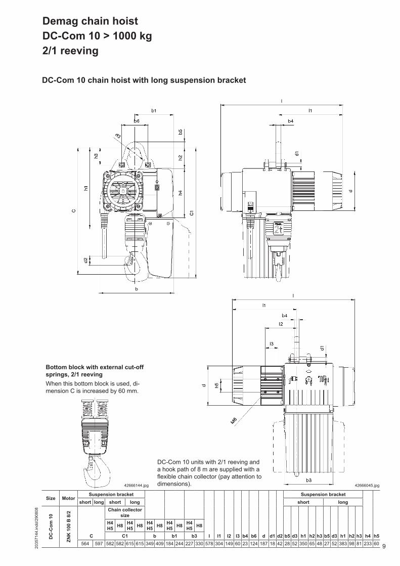
DC-Com 10 chain hoist with long suspension bracket
Demag chain hoistDC-Com 10 > 1000 kg2/1 reeving
42666045.jpg
Bottom block with external cut-off springs, 2/1 reevingWhen this bottom block is used, di-mension C is increased by 60 mm.
42666144.jpg
DC-Com 10 units with 2/1 reeving and a hook path of 8 m are supplied with a fl exible chain collector (pay attention to dimensions).
Size MotorSuspension bracket Suspension bracket
short long short long short long
DC
-Com
10
ZNK
100
B 8
/2
Chain collector size
H4H5 H8 H4
H5 H8 H4H5 H8 H4
H5 H8 H4H5 H8
C C1 b b1 b3 l l1 l2 l3 b4 b6 d d1 d2 b5 d3 h1 h2 h3 b5 d3 h1 h2 h3 h4 h5564 597 582 582 615 615 349 409 184 244 227 330 578 304 149 60 23 124 187 18 42 28 52 350 65 48 27 52 383 98 81 233 60

10 2035
7144
.indd
/290
808
DC-Com chain hoists are supplied with a long suspension bracket as standard. The short suspension bracket is available as an option.The suspension bracket facilitates installation, since the chain hoist can be directly suspended from the trolley. It is not necessary to dismantle existing trolleys.
Chain hoists with short or long suspension brackets can be combined with the following trolleys:
Suspension
Trolley load capacity
Flange width
Flange thickness
Crossbar diameter
DC 1 DC 2 DC 5 DC 10 DC 16 DC 25
[kg] [mm] [mm] [mm]
SWL chain hoist [kg] 80-125
80-250
160-500
315-1250
1250-2500
1250-1600
2500-3200
2000-2500
4000-5000
Reeving 1/1 2/1 1/1 2/1 1/1 2/1See next page for diagram
RU 3 450 60-90 12 211+2 1+2 1+2 1)
RU 6450
58-143 20 30144-300 18 35 1 1 1 1)
70058-143 20 30 1+2 1+2 1+2
144-300 18 38
1 1 1RU / EU 11 DK
850 58-30016
341350
58-143144-300 45
RU / EU 22 DK 2600 82-300 22 51 3+4 3+4 5 4)
RU / EU 36 DK 3600 106-30030
56 5 55
RU / EU 55 DK 5500106-186 70 5187-300 82,5
CF 5 550 50-91 15 161+2 1+2 1+2
U / EU 11 DC 110058-200
22 30
3+4 5)201-310
U / EU 22 DC 2200 82-20030 2) 40 1 1 1 3+4 6)
5U / EU 34 DC
2200 201-3103400 82-310
5 5RU / EU 56 DC 5600
98-20030 55 3 7) 3 7) 5
201-310
KBK trolley
100 1002 2 2I 300
II 600 3+4 3)
III 13001 1 1
3
KBK articulated frame(double trolley)
I 400II 1200
3III 2600 3
KBK crane traverse
100 200
1 1 1
I 600II 1400-2200
3III 2600 3
KBK crab frame
100 200I 600II 1200/2400
33
III 3300
1) up to 400 kg2) max. 28 mm for DC16/253) up to 500 kg4) Flange thickness max. 20 mm5) DC 10 - 1250 1/1 with U / EU 22 DC6) DC 10 - 2500 2/1 with U / EU 34 DC7) DC 10 with RU / EU 56 on request

112035
7144
.indd
/290
808
DC-Pro 1-5 suspension ringPart no.: 718 278 45for suspension parallel to track girder
42652159.jpg
DC-Pro 10 suspension ringPart no.: 715 278 45for suspension parallel to track girder
Suspension hook, folding
42699844.jpg
Optional suspensions
Size Part no. Dimensions [mm]
L b h d
DC 1-5 718 910 45 92 22 104 25DC 10 715 910 45 124 36 152 36
DC-Pro 16-25 suspension ringPart no.: 721 278 45including 2 adjusting ringsfor suspension parallel to track girder
42699245.jpg
Fig. 1 Fig. 2
Fig. 3 Fig. 4 Fig. 5
Operating limit switches for the upper and lower hook positions are available as an option (DC-Com 1 to DC-Com 10, 1/1 reeving). DC-Com 10 chain hoists, 2/1 reeving, are fi tted with limit switches as standard.
The upper end position must not be approached during normal operation, if the chain hoist is not provided with an operating limit switch (optional).
Limit switch
12 2035
7144
.indd
/290
808
Trolleys
The trolleys have the following product features:• Infi nitely variable adjustment of the fl ange width by means of adjusting rings,• U 11 travel rollers made of plastic (optional steel rollers),• U 22 / U 34 travel rollers made of steel,• Universal travel rollers for parallel and sloping running surfaces,• Travel rollers without fl anges, additional lateral steel guide rollers,• Integrated drop stops in the individual die-cast aluminium halves,• The side cheek surfaces are powder-coated.
The minimum permissible curve radius for push-travel trolleys is 1000 mm for U 11 and 2000 mm for U 22 / U 34 trolleys. However, to ensure good travel characteris-tics and a longer trolley service life, we recommend that much larger curve radii be used, e.g. 1500 mm or 3000 mm, respectively.The minimum permissible curve radius for electric-travel trolleys is 2000 mm (U 11) and 3000 mm (U 22 / U 34).Wear on the travel wheels strongly depends on the curve radius. The forces re-quired to move the load may strongly increase in the case of small curve radii in connection with high loads.
We recommend that steel travel rollers be used for:- frequent travel on curved tracks,- extreme ambient conditions (dirt accumulation, hot atmospheres, etc.),- heavily worn girders,- very heavy dead loads.U11-S 200 58-200 Part no. 716 535 45 l=290U11-S 310 On request
The travel wheels and guide rollers of four-wheel trolleys may display increased wear in installations featuring intensive operation, we recommend the use of EUDDC units for:- frequent travel on curved tracks with small curve radii (1000 mm) and high load
capacities,- automatic operation in connection with travel on curved tracks, small curve radii
(1000 mm) and high load capacities.
U 11 - U 34 travel on curved tracks
Trolleys with steel and spheroidal graphite cast iron travel rollers
EUDDC double-wheel articulated trolleys
Properties
132035
7144
.indd
/290
808
Curve radii of trolleys The specifi ed curve radii apply for normal applications.Contact the manufacturer or his representative for frequent curve travel operation (e.g. automatic installations).
Travel speedsSWL Chain hoist Reeving Possible cross-travel speeds in approx. ... m/min
V14/3,5 V12/4 V24/6 V40/10[kg] Type Trolley Travel drive Trolley Travel drive Trolley Travel drive Trolley Travel drive80 DC-Com 1
1/1
- - - -
U 11 DC E 11 DC
- -
to to1000 DC-Com 101250
DC-Com 10 2/1 U 22 DCU 34 DC E 22 DC1600
2000
Curve radii in mmTrolley size SWL Runway girder Travel wheel
materialPush travel Electric travel[kg] Flange width 2) Rmin Flange width 2) Rmin
CF 5 550 50-91 800 - - PlasticU 11 DC EU 11 DC 1100 58-310 1000 58-310 2000 Plastic 1)
U 22 DC EU 22 DC 2200 82-2002000
82-2003000
Spheroidal graphite cast iron
U 34 DC EU 34 DC2200 201-310 201-310 Spheroidal graphite
cast iron82-3103400 82-310
1) Steel travel rollers optional2) Max. fl ange width 500 mm (except CF 5)
14 2035
7144
.indd
/290
808
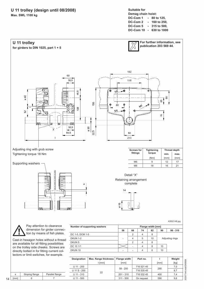
U 11 trolley (design until 08/2008)Max. SWL 1100 kg
Suitable forDemag chain hoist:DC-Com 1 - 80 to 125,DC-Com 2 - 160 to 250,DC-Com 5 - 315 to 500,DC-Com 10 - 630 to 1000
U 11 trolleyfor girders to DIN 1025, part 1 + 5
42652148.jpg
For further information, see publication 203 569 44.
s Sloping fl ange Parallel fl ange[mm] 6 7
Adjusting ring with grub screwTightening torque 18 Nm
Supporting washers
Number of supporting washers Flange width [mm]58 66 74 82 90 98 - 310
DC 1-5, DCM 1-5-
2 4 8Adjusting ringsDKUN 1-2 4 5 10
DKUN 5 2 4 8DC 10 1/1 - 4 8 10DKUN 10 - - 4 6 10
Screws for fi ttings
Tightening torque
Thread depthmin. max.
[Nm] [mm] [mm]M6 9 12 17M8 18 16 21
Detail “X”Retaining arrangement
complete
Pay attention to clearance dimension for girder connec-tion by means of fi sh plates.
Cast-in hexagon holes without a thread are available for all fi tting possibilities on the trolley side cheeks. Screws are directly bolted in for fi tting current col-lectors or limit switches, for example.
Designation Max. fl ange thickness Flange width Part no. l Weightt [mm] [mm] [mm] [kg]
U 11 - 200
2258 - 200
716 521 45290
7,0U 11 S - 200 716 535 45 8,7U 11 - 310 201 - 310 716 532 45 400 7,4U 11 - 500 311 - 500 On request 590 9,6
152035
7144
.indd
/290
808
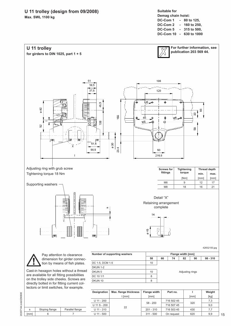
U 11 trolley (design from 09/2008)Max. SWL 1100 kg
Suitable forDemag chain hoist:DC-Com 1 - 80 to 125,DC-Com 2 - 160 to 250,DC-Com 5 - 315 to 500,DC-Com 10 - 630 to 1000
U 11 trolleyfor girders to DIN 1025, part 1 + 5
42652150.jpg
For further information, see publication 203 569 44.
s Sloping fl ange Parallel fl ange[mm] 6 7
Adjusting ring with grub screwTightening torque 18 Nm
Supporting washers
Number of supporting washers Flange width [mm]58 66 74 82 90 98 - 310
DC 1-5, DCM 1-5 10
Adjusting ringsDKUN 1-2DKUN 5 10DC 10 1/1 8DKUN 10 8
Screws for fi ttings
Tightening torque
Thread depthmin. max.
[Nm] [mm] [mm]M6 9 12 17M8 18 16 21
Detail “X”Retaining arrangement
complete
Pay attention to clearance dimension for girder connec-tion by means of fi sh plates.
Cast-in hexagon holes without a thread are available for all fi tting possibilities on the trolley side cheeks. Screws are directly bolted in for fi tting current col-lectors or limit switches, for example.
Designation Max. fl ange thickness Flange width Part no. l Weightt [mm] [mm] [mm] [kg]
U 11 - 200
2258 - 200
716 502 45320
7,3U 11 S - 200 716 507 45 9,0U 11 - 310 201 - 310 716 503 45 430 7,7U 11 - 500 311 - 500 On request 620 9,9
16 2035
7144
.indd
/290
808
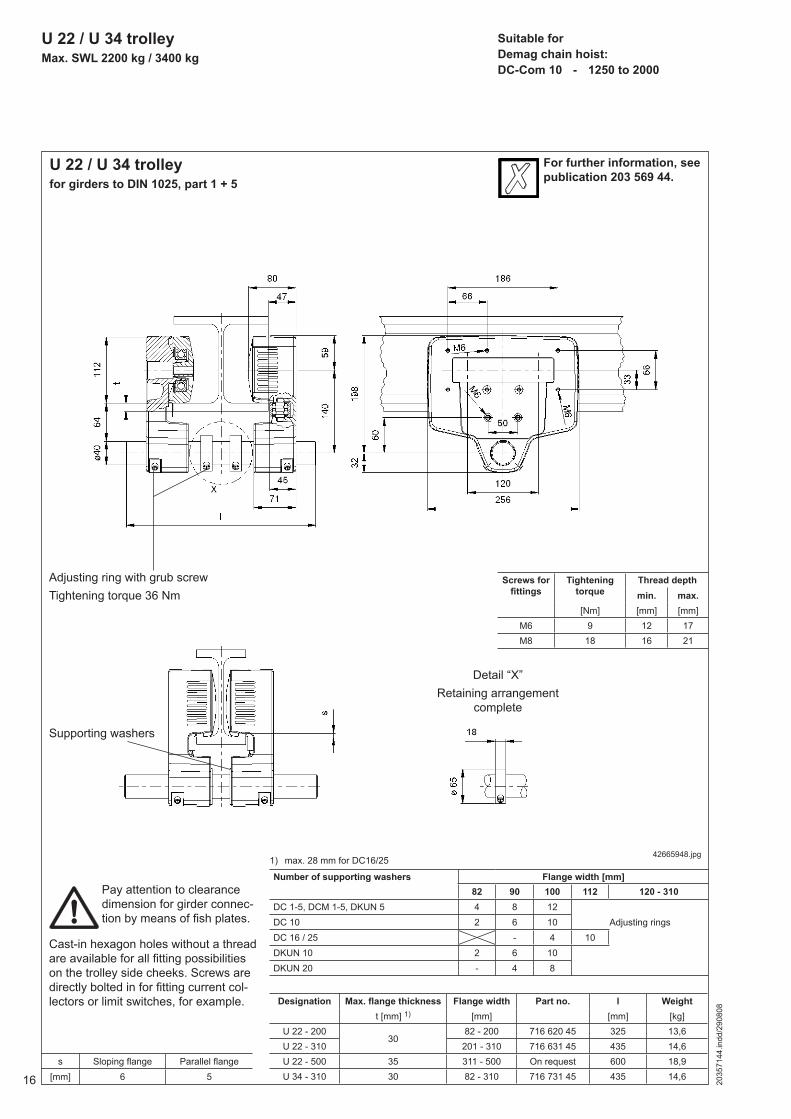
U 22 / U 34 trolleyMax. SWL 2200 kg / 3400 kg
Suitable forDemag chain hoist:DC-Com 10 - 1250 to 2000
U 22 / U 34 trolleyfor girders to DIN 1025, part 1 + 5
42665948.jpg
Designation Max. fl ange thickness Flange width Part no. l Weightt [mm] 1) [mm] [mm] [kg]
U 22 - 20030
82 - 200 716 620 45 325 13,6U 22 - 310 201 - 310 716 631 45 435 14,6U 22 - 500 35 311 - 500 On request 600 18,9U 34 - 310 30 82 - 310 716 731 45 435 14,6
For further information, see publication 203 569 44.
s Sloping fl ange Parallel fl ange[mm] 6 5
Adjusting ring with grub screwTightening torque 36 Nm
Supporting washers
Number of supporting washers Flange width [mm]82 90 100 112 120 - 310
DC 1-5, DCM 1-5, DKUN 5 4 8 12DC 10 2 6 10 Adjusting ringsDC 16 / 25 - 4 10DKUN 10 2 6 10DKUN 20 - 4 8
1) max. 28 mm for DC16/25
Screws for fi ttings
Tightening torque
Thread depthmin. max.
[Nm] [mm] [mm]M6 9 12 17M8 18 16 21
Detail “X”Retaining arrangement
complete
Pay attention to clearance dimension for girder connec-tion by means of fi sh plates.
Cast-in hexagon holes without a thread are available for all fi tting possibilities on the trolley side cheeks. Screws are directly bolted in for fi tting current col-lectors or limit switches, for example.
172035
7144
.indd
/290
808
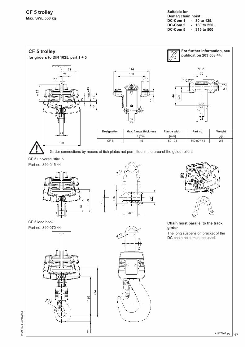
Suitable forDemag chain hoist:DC-Com 1 - 80 to 125,DC-Com 2 - 160 to 250,DC-Com 5 - 315 to 500
CF 5 trolleyMax. SWL 550 kg
CF 5 trolleyfor girders to DIN 1025, part 1 + 5
Girder connections by means of fi sh plates not permitted in the area of the guide rollers
t max
.=15
Designation Max. fl ange thickness Flange width Part no. Weightt [mm] [mm] [kg]
CF 5 15 50 - 91 840 007 44 2,6
CF 5 universal stirrupPart no. 840 045 44
CF 5 load hookPart no. 840 070 44
41777947.jpg
For further information, see publication 203 568 44.
Chain hoist parallel to the track girderThe long suspension bracket of the DC chain hoist must be used.
18 2035
7144
.indd
/290
808
Selection table
1) Possible with different parameter setting2) Max. gradient 1%, > 1% on request3) In connection with DCS (stepless) from 0,5 m/min to vmax
13
6
5
7
4
2
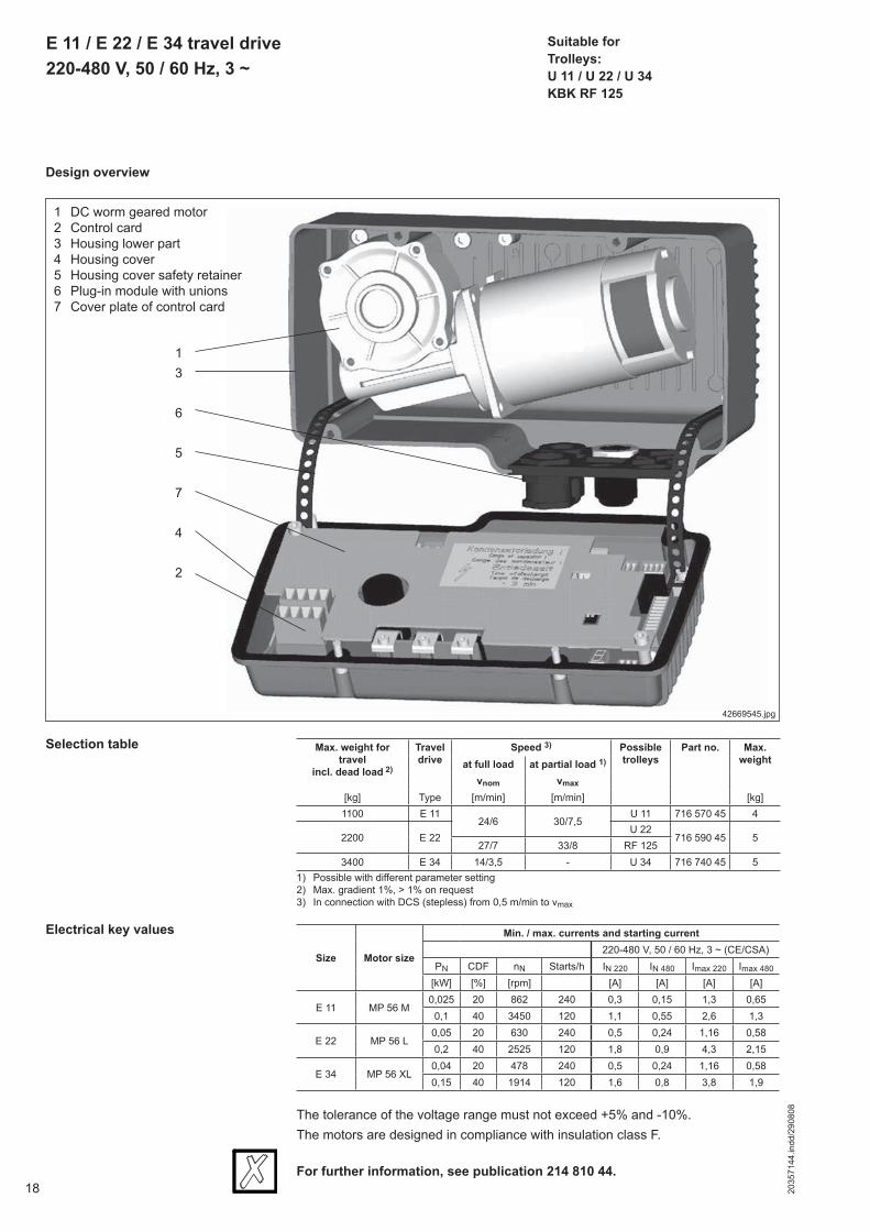
E 11 / E 22 / E 34 travel drive220-480 V, 50 / 60 Hz, 3 ~
Suitable forTrolleys:U 11 / U 22 / U 34KBK RF 125
Design overview
Size Motor size
Min. / max. currents and starting current220-480 V, 50 / 60 Hz, 3 ~ (CE/CSA)
PN CDF nN Starts/h IN 220 IN 480 Imax 220 Imax 480
[kW] [%] [rpm] [A] [A] [A] [A]
E 11 MP 56 M0,025 20 862 240 0,3 0,15 1,3 0,65
0,1 40 3450 120 1,1 0,55 2,6 1,3
E 22 MP 56 L0,05 20 630 240 0,5 0,24 1,16 0,580,2 40 2525 120 1,8 0,9 4,3 2,15
E 34 MP 56 XL0,04 20 478 240 0,5 0,24 1,16 0,580,15 40 1914 120 1,6 0,8 3,8 1,9
Electrical key values
The tolerance of the voltage range must not exceed +5% and -10%.The motors are designed in compliance with insulation class F.
For further information, see publication 214 810 44.
1 DC worm geared motor2 Control card3 Housing lower part4 Housing cover5 Housing cover safety retainer6 Plug-in module with unions7 Cover plate of control card
Max. weight for travel
incl. dead load 2)
Travel drive
Speed 3) Possible trolleys
Part no. Max. weightat full load at partial load 1)
vnom vmax
[kg] Type [m/min] [m/min] [kg]1100 E 11
24/6 30/7,5U 11 716 570 45 4
2200 E 22U 22
716 590 45 527/7 33/8 RF 125
3400 E 34 14/3,5 - U 34 716 740 45 5
42669545.jpg
192035
7144
.indd
/290
808
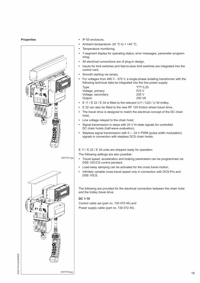
Properties • IP 55 enclosure,• Ambient temperature -20 °C to + +40 °C,• Temperature monitoring,• 7-segment display for operating status, error messages, parameter program-
ming;• All electrical connections are of plug-in design,• Inputs for limit switches and fast-to-slow limit switches are integrated into the
control card,• Smooth starting via ramps,• For voltages from 480 V - 575 V, a single-phase isolating transformer with the
following technical data be integrated into the line power supply: Type: TTT 0,25 Voltage, primary: 575 V Voltage, secondary: 230 V Output: 250 VA• E 11 / E 22 / E 34 is fi tted to the relevant U11 / U22 / U 34 trolley,• E 22 can also be fi tted to the new RF 125 friction wheel travel drive,• The travel drive is designed to match the electrical concept of the DC chain
hoist,• Line voltage relayed to the chain hoist;• Signal transmission in steps with 24 V tri-state signals for controlled
DC chain hoists (half-wave evaluation),• Stepless signal transmission with 0 -– 24 V PWM (pulse width modulation)
signals in connection with stepless DCS chain hoists.
E 11 / E 22 / E 34 units are shipped ready for operation.The following settings are also possible:• Travel speed, acceleration and braking parameters can be programmed via
DSE-10C/CS control pendant,• Load-sway damping can be activated for the cross travel motion,• Infi nitely variable cross-travel speed only in connection with DCS-Pro and
DSE-10CS.
The following are provided for the electrical connection between the chain hoist and the trolley travel drive:
DC 1-10Control cable set (part no. 720 070 45) andPower supply cable (part no. 720 072 45).
42670747.jpg
42670746.jpg

20 2035
7144
.indd
/290
808
E 22 travel drive on KBK RF 125
42670544.jpgSpring length with washer when pretensioned 47 mm.
For further information on RF 125 trolleys, see publication 202 976 44.

212035
7144
.indd
/290
808
E 11 / E 22 / E 34 travel drive on U 11 / U 22 / U 34 trolley
42669454.jpg
Trolley A1 B H X1 X2 X3 T1[mm] [mm] [mm] [mm] [mm] [mm] [mm]
EU 11 58 273 98 50 68 115 41EU 22 / EU 34 60 288 112 68 44 117 49
Application as a long travel drive on bottom fl anges is not recommended because of the single-wheel drive.We recommend horizontal mounting of the travel drive for outdoor operation.
22 2035
7144
.indd
/290
808
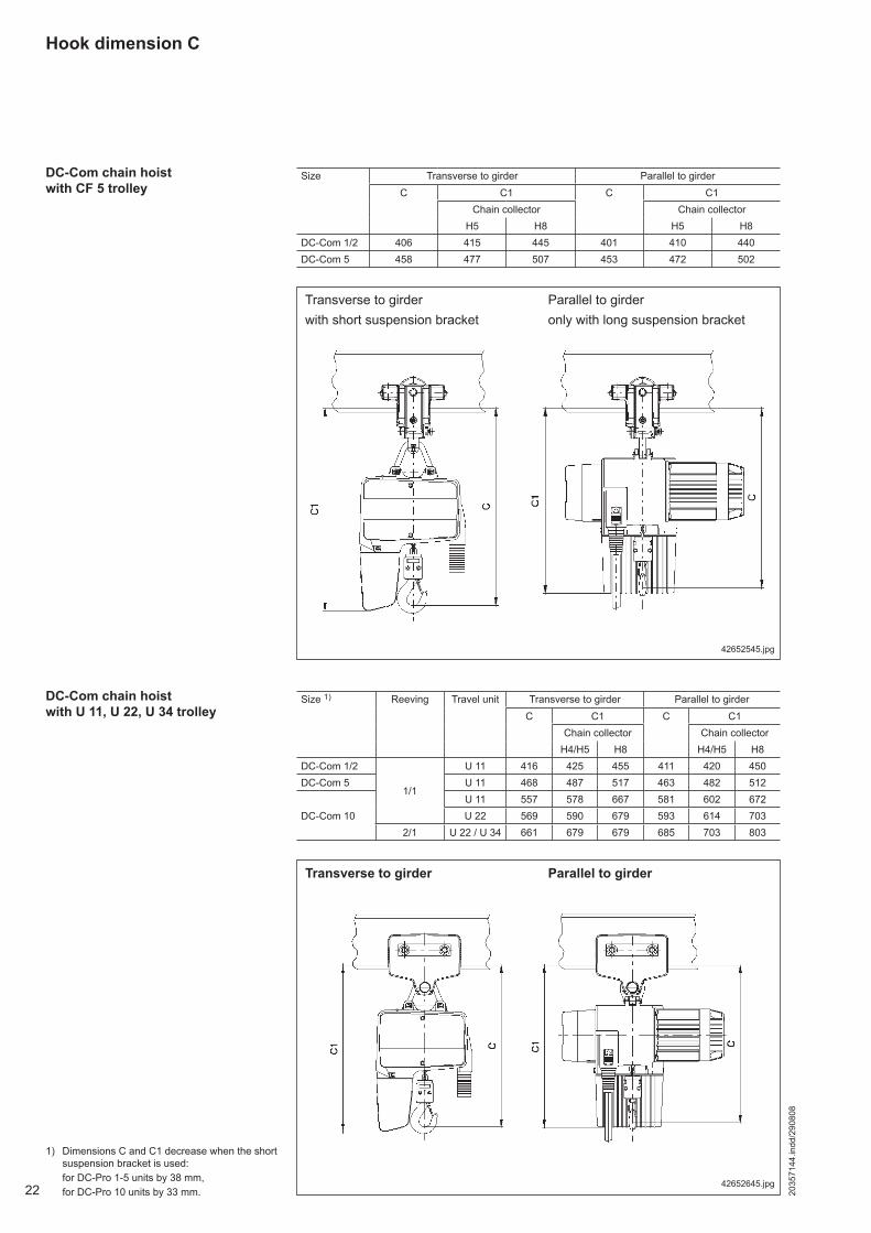
DC-Com chain hoist with CF 5 trolley
42652545.jpg
42652645.jpg
DC-Com chain hoist with U 11, U 22, U 34 trolley
Transverse to girder Parallel to girder
Hook dimension C
Transverse to girderwith short suspension bracket
Parallel to girderonly with long suspension bracket
1) Dimensions C and C1 decrease when the short suspension bracket is used:
for DC-Pro 1-5 units by 38 mm, for DC-Pro 10 units by 33 mm.
Size 1) Reeving Travel unit Transverse to girder Parallel to girderC C1 C C1
Chain collector Chain collectorH4/H5 H8 H4/H5 H8
DC-Com 1/2
1/1
U 11 416 425 455 411 420 450DC-Com 5 U 11 468 487 517 463 482 512
DC-Com 10U 11 557 578 667 581 602 672U 22 569 590 679 593 614 703
2/1 U 22 / U 34 661 679 679 685 703 803
Size Transverse to girder Parallel to girderC C1 C C1
Chain collector Chain collectorH5 H8 H5 H8
DC-Com 1/2 406 415 445 401 410 440DC-Com 5 458 477 507 453 472 502
232035
7144
.indd
/290
808
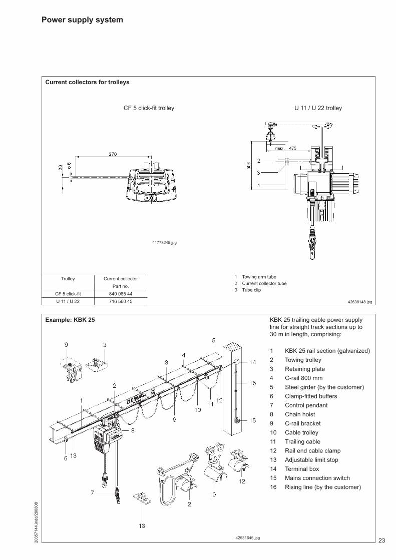
Power supply system
41778245.jpg
1 Towing arm tube2 Current collector tube3 Tube clip
42531645.jpg
Current collectors for trolleys
Trolley Current collectorPart no.
CF 5 click-fi t 840 085 44U 11 / U 22 716 560 45
CF 5 click-fi t trolley U 11 / U 22 trolley
Example: KBK 25 KBK 25 trailing cable power supply line for straight track sections up to 30 m in length, comprising:
1 KBK 25 rail section (galvanized)2 Towing trolley3 Retaining plate4 C-rail 800 mm5 Steel girder (by the customer)6 Clamp-fi tted buffers7 Control pendant8 Chain hoist9 C-rail bracket10 Cable trolley11 Trailing cable12 Rail end cable clamp13 Adjustable limit stop14 Terminal box15 Mains connection switch16 Rising line (by the customer)
42638148.jpg

Prin
ted
in G
erm
any
Reproduction in whole or in part only with prior consent of Demag Cranes & Components GmbH, D-58286 Wetter Subject to change. Not liable for errors or omissions.
The current addresses of the sales offi ces in Germany and the subsidiaries and agencies worldwide can be found on the Demag Cranes & Components homepageat www.demagcranes.com ► Contact and Demag worldwide


![[XLS] · Web viewHOIST HOIST EQUIPMENT ACTUATOR, MLG HOIST HOIST EQUIPMENT - ACTUATOR, MLG HOIST HOIST - CARDAN PIN HOIST HOIST-CARDAN PIN HOIST HOIST-DEVICE,FLAP TRACK 2-5 HOIST](https://static.fdocuments.in/doc/165x107/5b1fa5177f8b9aa64c8b4800/xls-web-viewhoist-hoist-equipment-actuator-mlg-hoist-hoist-equipment-actuator.jpg)