TECHNICAL CRITERIA
26
TECHNICAL CRITERIA THE PLACE TO SHOP FASHION OUTLETS OF NIAGARA FALLS
Transcript of TECHNICAL CRITERIA

TH
E P
LAC
E T
O S
HO
P
T E C H N I C A L C R I T E R I A
TH
E P
LAC
E T
O S
HO
P
FASHION OUTLETS OF NIAGARA FALLS

t2
November, 2011 Manual Generated
April, 2012 Updated manual per TC
March, 2014 Distribution of utilities through exit corridors is prohibited with exception. (t13)
June, 2014 Reference to the Guidelines for the SSDS and repair of the Vapor Barrier if penetrated. (t6 - t16)
March, 2015 Updated Plumbing content to list specific location for main water shut off valve to be at eye level. (t19 #3)
April, 2016 Added Water Efficiency language. (t20 H)
April, 2017 Removed language regarding Telephone Service (t22 [P] Replaced with language regarding Communications Services (t22)
January, 2018 Updated current layout
ADDENDUM LOG FASHION OUTLETS OF NIAGARA FALLS

t3
TECHNICAL CRITERIA
General Criteria t4-t5
Building Foundation Concrete Cap and Sub-Slab Depressurization System Detail t6
Stego Wrap Vapor Barrier/Retarder Installation Instructions t7-t12
Stego Industries Trench Scenarios t13-t16
HVAC Design t17-t18
Plumbing Design Criteria t19-t21
Electrical Design Criteria t22-t24
Tenant Kitchen Exhaust Systems (where applicable) t25-t26
Exit Corridors t26
PLEASE VISITWWW.MACERICH.COM
TO VIEWPLAN SUBMITTAL & APPROVAL
PROCEDURESand CONTRACTOR RULES &
REGULATIONS
TABLE OF CONTENTS FASHION OUTLETS OF NIAGARA FALLS

t4
G E N E R A L C R I T E R I A
GENERAL CRITERIA
Prior to starting construction, Tenant must confirm existing conditions of the premises. Coordinate site visits with Landlord’s Tenant Coordinator.
A. All plans, specifications and calculations shall be prepared under the supervision of a Registered Professional Engineer holding a valid registration in the State of New York in the applicable fields of engineering. 1/4” scale floor plans shall be provided showing each of the following disciplines: HVAC (including exhaust and makeup air), electrical and plumbing. Include as a minimum electric panelboard schedules, one line diagram and fully circuited electric floor plans, HVAC duct, equipment and controls, reflected ceiling plan and roof plan (if applicable), plumbing floor plan and riser diagram, and kitchen exhaust hood elevation, where applicable. Further requirements for plans to be submitted are found within the individual sections which follow. Include fire protection sprinkler layout with reference to compliance with Code and I.S.O. requirements.
B. The Tenant’s engineer shall refer to and abide by this Fashion Outlets of Niagara Falls MEP Design Criteria For Tenant Improvements, Tenant Handbook, Design Criteria, and the Lease for submission requirements and other guidelines set forth for the design and construction of all items in the Tenant’s Premises.
C. All work shall be done in accordance with the requirements of the New York State Fire and Building Code, NFPA Standards, the Americans with Disabilities Act (ADA) and all-applicable codes and regulations. Additionally, food service facilities must adhere to the pertinent Department of Health regulations, Sanitary Codes, and all other applicable codes. Certain code-required items
are mentioned in these criteria for emphasis or example only. Identification and compliance with all applicable codes and regulations are the Tenant’s responsibility.
D. The design and appearance of all light fixtures and exposed ductwork and piping which are visible from the public areas are critical to the overall visual effect, and are subject to detailed review and approval by the Landlord.
E. All piping and ductwork is to be installed as high as reasonably possible and run parallel to the structure. Landlord’s structural engineer, at Tenant’s expense, prior to the start of any work must approve all holes through structural members or slabs.
F. All openings through structurally supported slabs must be core-bored, sleeved, grouted, sealed and made water and fireproof. Sleeves, except for water closets, janitor sinks and floor drains, must extend at least two inches (2”) above the finished floor. Landlord must approve the location of all floor openings in writing. Waterproofing must be inspected and approved by the Landlord before any flooring material is installed. The Tenant is responsible for taking whatever measures are necessary (including but not limited to those measures prescribed by the Landlord in the exercise of its reasonable judgment) to assure that core-boring will not damage Landlord’s structure, conduits, etc. The costs of such tests or repair of any damage will be borne by the Tenant.
FASHION OUTLETS OF NIAGARA FALLS

t5
C O N T I N U E D
G. Noise and Vibration Control. All equipment installed by Tenant shall be provided with vibration isolators, sound traps, duct lining, acoustic housings, acoustical louvers and other noise and vibration control apparatus required to limit intrusion into adjacent spaces accordingly:1. Intrusive noise levels transmitted to adjacent spaces shall not exceed NC-25
when measured in the adjacent tenants’ spaces.2. Tenant equipment noise emitted to the exterior shall not exceed 45 dBA. At
any time within the first six months of occupancy or within the first six months after installation of any new equipment which produces noise and vibration, the Landlord may request a test by an acoustical consultant of its choice to verify compliance with the above minimum acoustical requirements. Should the Tenant be in compliance, the Landlord will pay the costs of the testing. Should the Tenant not be in compliance, Tenant will pay the costs of the initial testing, shall make whatever changes are required to bring the installation into compliance, and shall pay the costs of all subsequent testing by an acoustical consultant approved by the Landlord to verify compliance.
H. The Tenant shall be responsible for coordinating all Tenant work with Landlord’s work and building. In the event that Tenant’s work causes any modifications to Landlord’s work or building, the Tenant must notify the Landlord before any work is done and shall reimburse the Landlord for its direct expenses.
I. In the event the Tenant is notified of any violations of codes, or ordinances, or regulations, or of its obligations hereunder, either by the jurisdictional authorities or by the Landlord, the Tenant shall correct such violations within seven (7) calendar days from the date of such notification. Should the Tenant fail to correct such violations within this period, the Landlord shall have the right to correct such
violations at the Landlord’s cost plus an administrative fee and bill Tenant for same. Tenant is also responsible for any incidental expenses or damages to Landlord or to third parties resulting from its violation(s) or failure to comply with the requirements set forth herein.
J. No openings for fans, vents, louvers, grilles, or other devices shall be installed in any demising partition, exterior wall, or roof without Landlord’s prior written approval. All roof openings, blocks and flashing must be done by the Landlord’s approved roofing contractor at the Tenant’s expense. The Landlord’s roofing contractor is TBD.
K. In the event of any conflict between local codes or regulations and these criteria, local codes or regulations shall govern, and the matter shall be brought to the Landlord’s attention via written notice from Tenant.
L. All sawcutting, trenching and excavation must adhere to the guidelines for the sub-slab depressurization system. If penetrated, the vapor barrier must be repaired and maintained to all applicable manufacturer guidelines and details (see the following 8 pages).
G E N E R A L C R I T E R I A
FASHION OUTLETS OF NIAGARA FALLS

t6
G E N E R A L C R I T E R I A
FASHION OUTLETS OF NIAGARA FALLS

t7
UNDER-SLAB INSTRUCTIONS1. Stego Wrap can be installed over an aggregate, sand, or
tamped earth base. It is not necessary to have a cushion layer or sand base, as Stego Wrap is tough enough to withstand rugged construction environments.
2. Unroll Stego Wrap over the area where the slab is to be placed. Stego Wrap should completely cover the concrete placement area. All joints/seams both lateral and butt should be overlapped a minimum of six inches and taped using Stego Tape.
NOTE: The area of adhesion should be free from dust, dirt, moisture, and frost to allow maximum adhesion of the pressure-sensitive tape.
FIGURE 1: UNDER-SLAB INSTALLATION
IMPORTANT: Please read these installation instructions completely, prior to beginning any Stego Wrap installation. The following installation instructions are based on ASTM E 1643 - Standard Practice for Selection, Design, Installation, and Inspection of Water Vapor Retarders Used in Contact with Earth or Granular Fill Under Concrete Slabs. If project specifications call for compliance with ASTM E 1643, then be sure to review the specific installation sections outlined in the standard along with the techniques referenced in these instructions.
STEGO WRAP VAPOR BARRIER/RETARDER INSTALLATION INSTRUCTIONS - Part 1
STEGO WRAP VAPOR BARRIER/RETARDER INSTALLATION INSTRUCTIONS - Part 1
FASHION OUTLETS OF NIAGARA FALLS

t8
C O N T I N U E D
1. ASTM E 1643 requires sealing the perimeter of the slab. Extend vapor retarder over footings and seal to foundation wall, grade beam, or slab at an elevation consistent with the top of the slab or terminate at impediments such as waterstops or dowels. Consult the structural engineer of record before proceeding.
SEAL TO SLAB AT PERIMETER:*NOTE: Clean the surface of Stego Wrap to ensure that the area of adhesion is free from dust, dirt, moisture and frost to allow maximum adhesion of the pressure-sensitive adhesive.
a. Install Crete Claw on the entire perimeter edge Stego Wrap.
b. Prior to the placement of concrete, ensure that the top of Crete Claw is free of dirt, debris or mud to maximize the bond to the concrete.
FIGURE 2a: SEAL TO SLAB PERIMETER
STEGO WRAP VAPOR BARRIER/RETARDER INSTALLATION INSTRUCTIONS - Part 1
FASHION OUTLETS OF NIAGARA FALLS
t9
C O N T I N U E D
STEGO WRAP VAPOR BARRIER/RETARDER INSTALLATION INSTRUCTIONS - Part 1
OR SEAL TO PERIMETER WALL OR FOOTING WITH STEGOTACK TAPE.a. Make sure area of adhesion of free of dust, dirt, debris, moisture and frost to allow maximum adhesion.b. Remove release liner on one side and stick to desired surface.c. When ready to apply Stego Wrap, remove the exposed release liner and press Stego Wrap firmly against StegoTack Tape to secure.*If ASTM E 1643 is specified, consult with project architect and structural engineer to determine which perimeter seal technique should be employed for the project.
FIGURE 2b: SEAL TO PERIMETER WALL FIGURE 2c: SEAL TO FOOTING
FASHION OUTLETS OF NIAGARA FALLS

t10
C O N T I N U E D
1. In the event that Stego Wrap is damaged during or after installation, repairs must be made. Stego Tape can be used to repair small holes in the material. For larger holes, cut a piece of Stego Wrap to a size and shape that covers any damage by a minimum overlap of six inches in all directions. Clean all adhesion areas of dust, dirt, moisture, and frost. Tape down all edges using Stego Tape (see figure 3, Sealing Damaged Areas).
FIGURE 3: SEALING DAMAGED AREAS
FIGURE 4a: PIPE PENETRATION SEALING
2. IMPORTANT: ALL PENETRATIONS MUST BE SEALED. All pipe, ducting, rebar, wire penetrations and block outs should be sealed using Stego Wrap, Stego Tape and/or Stego Mastic (see figure 4a, Pipe Penetration Sealing).
STEGO WRAP PIPE PENETRATION REPAIR DETAIL:
1. Install Stego Wrap around pipe penetrations by slitting/cutting material as needed. Try to minimize the void space created.
2. If Stego Wrap is close to pipe and void space is minimized then seal around pipe penetration with Stego Tape and/or Stego Mastic. (See Figure 4a)
STEGO WRAP VAPOR BARRIER/RETARDER INSTALLATION INSTRUCTIONS - Part 1
STEGO WRAP VAPOR BARRIER/RETARDER INSTALLATION INSTRUCTIONS - Part 1
FASHION OUTLETS OF NIAGARA FALLS

t11
C O N T I N U E D
1. If detail patch is needed to minimize void space around penetration, then cut a detail patch to a size and shape that creates a six inch overlap on all edges around the void space at the base of the pipe. Stego Pre-Cut Pipe Boots are also available to speed up the installation.
2. Cut an “X” the size of the pipe diameter in the center of the pipe boot and slide tightly over pipe.
3. Tape down all sides of the pipe boot with Stego Tape.
4. Seal around the base of the pipe using Stego Tape and/or Stego Mastic. (See Figure 4b)
FIGURE 4b: DETAIL PATCH FOR PIPE PENETRATION SEALING
MULTIPLE PIPE PENETRATION SEALING:Multiple pipe penetrations in close proximity and very small pipes may be sealed using Stego Wrap and Stego Mastic for ease of installation (see figure 5, Multiple Pipe Penetration Sealing).
STEGO WRAP VAPOR BARRIER/RETARDER INSTALLATION INSTRUCTIONS - Part 1
FASHION OUTLETS OF NIAGARA FALLS

t12
CRAWL SPACE INSTALLATION INSTRUCTIONS:1. Turn Stego Wrap up the foundation wall to a minimum height of six inches above the outside/exterior grade or in compliance with local building
codes and terminate with Stego Term Bar. To form a complete seal, apply StegoTack Tape or a layer of Stego Mastic to the foundation wall prior to installing Stego Term Bar. Allow one hour for Stego Mastic to cure prior to installing Stego Term Bar.
FIGURE 6: CRAWL SPACE INSTALLATION2. Seal Stego Wrap around all penetrations
and columns using Stego Tape, StegoTack Tape, and/or Stego Mastic.
3. Place Stego Wrap directly over the crawl space floor. If rigid insulation is to be used, install Stego Wrap prior to insulation (under insulation and between the foundation wall and insulation).
4. Overlap seams a minimum of six inches and seal with Stego Tape. Some codes require a minimum of a twelve inch overlap. Check appropriate codes prior to installation.
NOTE: Stego Wrap Vapor Barrier and Stego Tape are both available in white (as shown in illustration above).
INSTALLATION TIP:1. For a cleaner look and to prevent against
tenting of Stego Wrap at the foundation wall/foundation floor intersection, consider mechanically fastening Stego Wrap to base of foundation wall in addition to the above mentioned wall termination.
STEGO WRAP VAPOR BARRIER/RETARDER INSTALLATION INSTRUCTIONS - Part 2
FASHION OUTLETS OF NIAGARA FALLS
t13
STEGO INDUSTRIES TRENCH REPAIR SCENARIOS
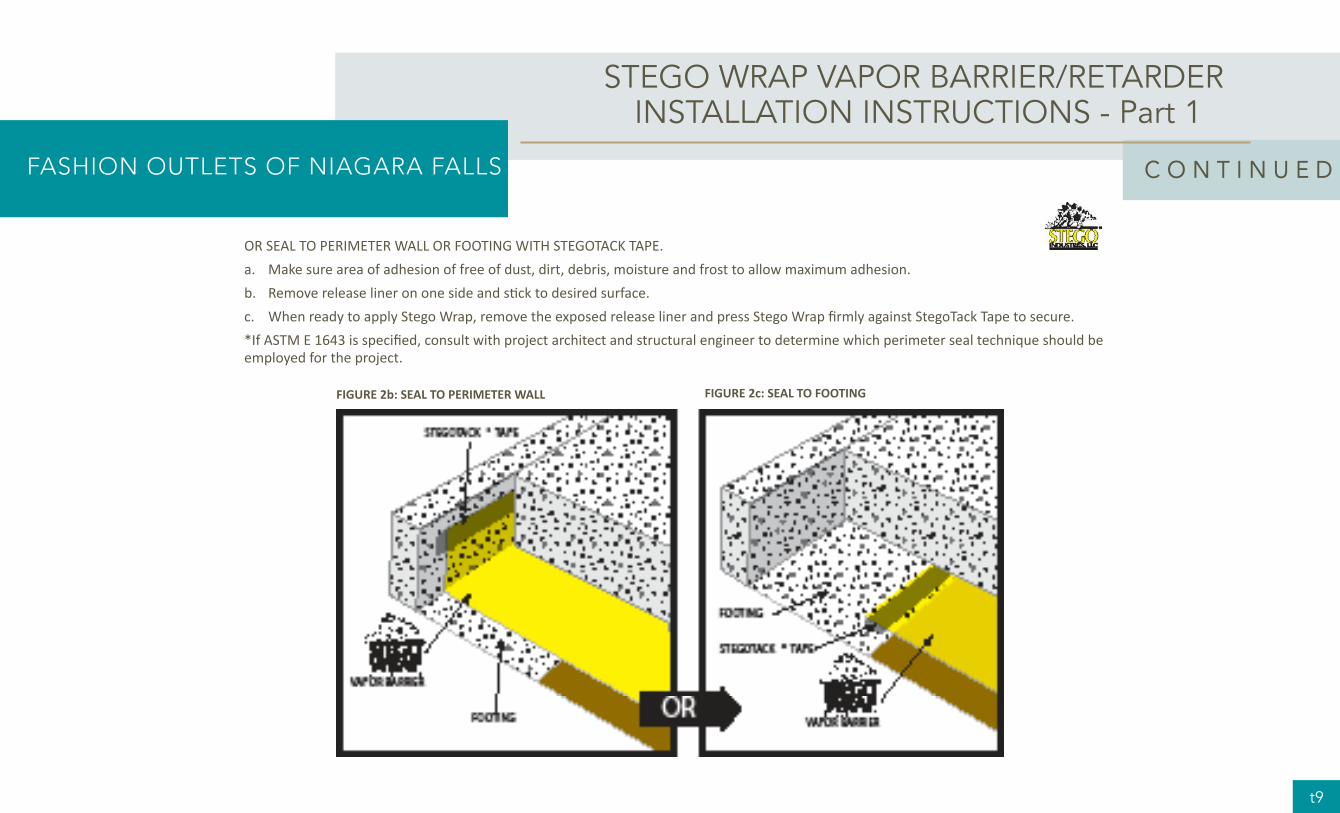
Stego Industries, LLC recommends that Stego Wrap is installed in compliance with the latest version of the prevailing installation standard, ASTM E1643. When applied to trench repair, in most instances the critical aspect is creating the 6 inch overlap required by the standard. The ability to successfully create the proper overlap depends on a variety of factors, most importantly advanced planning. This technical memo demonstrates four potential repair options that may not take into account local building codes or project specific conditions. The following options do not supersede contract documents, and as such, the repair method utilized must be approved by a licensed design professional.
Scenario 1 – A Fill Course Was Used
In the event that a fill course* was used above the vapor barrier, the following method can be utilized. Figure 1 below shows that with a fill course above the membrane, saw cuts can be made without damaging the vapor barrier.
FIGURE 1
STEGO INDUSTRIES TRENCH REPAIR SCENARIOS
FASHION OUTLETS OF NIAGARA FALLS

t14
Scenario 2 – Advanced Planning
If there is no fill course above the vapor barrier and a trench needs to be cut in the concrete, the following method can be utilized to create the 6 inch overlap called for by ASTM E1643:
Cut through the concrete and the vapor barrier and remove a smaller section (6 inches on each side) in the center of your intended trench location as seen in Figures 2A and 2B.
With an understanding of the concrete thickness obtained from the initial cuts, create two more cuts just shy of the full concrete depth at the full width of the intended trench as seen in Figure 2B. Break the cut sections and remove as seen in Figure 2C. You will be left with enough material to create a six inch overlap when it is time to repair the trench as seen in Figure 2D.
FIGURE 2a
FIGURE 2b
FIGURE 2c
FIGURE 2d
STEGO INDUSTRIES TRENCH REPAIR SCENARIOS
FASHION OUTLETS OF NIAGARA FALLS

t15
Scenario 3 – No Advanced Planning Dig Out
In the event that the trench has already been cut and 1643 compliance is required by the design professional, the only way we know of to achieve the overlap is to dig out beneath the vapor barrier to expose enough of the membrane for overlapping. Next, tape the repair membrane to the existing vapor barrier with 6 inches of overlap. Finally, fill trench with replacement concrete making sure to fill any voids created. This is not an ideal method as in many cases this is impractical, expensive, or even impossible to achieve. This process is detailed in Figures 3A, 3B, and 3C.
FIGURE 3a
FIGURE 3b
FIGURE 3c
STEGO INDUSTRIES TRENCH REPAIR SCENARIOS
FASHION OUTLETS OF NIAGARA FALLS

t16
Scenario 4 – No Advanced Planning Patch
Although not 1643 compliant, the following method may be the only practical/possible way to detail an already-cut trench. In this scenario, the repair piece of Stego Wrap is cut to fit in the trench and is sealed with either Stego Mastic or StegoTack Tape. By definition, this is not a Stego preferred method due to its non-compliance with ASTM E1643. The method is detailed in Figure 4:
FIGURE 3a
STEGO INDUSTRIES TRENCH REPAIR SCENARIOS
FASHION OUTLETS OF NIAGARA FALLS
t17
HVAC DESIGN
HVAC DESIGN
A. Landlord will furnish and install an all-electric roof top mounted single packaged heating and cooling unit sized to approximately one ton per 350 square feet of space. Landlord will provide a roof curb and all associated support framing and roof work. An empty conduit will be provided from the Tenant’s premises to the RTU. Power to the unit and start up of the unit are Tenant’s responsibility.
B. Tenant is responsible for the design of the Tenant’s HVAC duct and temperature control system. All calculations shall be in accordance with the latest edition of the ASHRAE Handbooks, all applicable codes and regulations, and good engineering practice. All calculations shall be certified by a New York Registered Professional Engineer and the results submitted to Landlord for approval.1. Design must comply with criteria.2. Field verification of existing HVAC RTU information is the responsibility of the
Tenant.3. If additional rooftop units are needed to meet the Tenant’s tonnage
requirements or if existing equipment is of a condition that it may not be reused, new equipment is to be supplied and installed by the Tenant at the Tenant’s expense. Removal and disposal of old equipment is by the Tenant at the Tenant’s expense.
C. Rooftop HVAC equipment shall be located directly above the Tenant Premises or as approved by the Landlord. Tenant shall install all other HVAC equipment within the Tenant’s premises including air handling equipment for split systems, controls, ductwork, fire dampers where required, electric connections, electric duct heat, and balancing. Tenant shall provide access panels at all equipment for service access.
D. Outside air ventilation when needed shall be provided through the roof at a point above the Tenant’s space. All design of the ventilation system and installation shall be by the Tenant at the Tenant’s sole expense.
E. To meet exhaust requirements the Tenant shall provide rooftop equipment above its space and penetrate the roof to its ceiling space. The exhaust fan and associated ductwork is provided by the Tenant.
1. Toilet exhaust is vented to the roof.
2. Relief of any excess outside air shall be vented to a Tenant exhaust system.3. All odorous or otherwise unacceptable air as determined by Landlord shall be
removed by means of a ducted exhaust system with a centrifugal exhaust fan ducted to the outside of the building at the roof.
4. Air should not flow from the food preparation areas to dining and waiting areas or to other portions of the Landlord’s building.
F. Tenant’s rooftop units shall be selected based on the cooling and heating load requirements of the space served.
G. Tenant’s HVAC system shall be a stand alone system.
FASHION OUTLETS OF NIAGARA FALLS
t18
C O N T I N U E D
H. Ductwork1. The Tenant ductwork shall be fabricated from galvanized sheet metal and be in
compliance with all SMACNA Standards. All duct branches off of the main trunk line shall be installed with volume dampers to allow for proper balancing. If the dampers are located above an inaccessible ceiling, a remote operator or ceiling access panel shall be installed.
2. Flexible ductwork shall be factory insulated and shall only be used for tie-ins from the trunk line or branch duct to the air distribution devices. Flexible ductwork shall be limited to a maximum length of 6 feet.
3. Air distribution devices shall be located per the engineered drawings and to ensure proper air flow. Air distribution devices shall be of steel or aluminum construction.
4. All supply, return, and outside air ductwork shall be externally insulated, except where ductwork is internally lined, with minimum R-4.2 insulation. All joints and seams of the insulation shall be stapled and sealed.
5. Fiberglass duct is not permitted.I. All walk-in coolers, refrigerators or freezer boxes shall be provided with insulated
floor systems, as recommended by the equipment manufacturer. The combined weight of either the walk-in cooler, refrigerator or freezer box, together with the contents therein, shall not exceed the allowable floor load. Tenant shall provide a dry type sprinkler head in walk-in coolers if required by code.
J. Ceiling mounted fan units, piping, heaters, fans and ductwork may be attached to the Landlord’s structure, subject to the following:1. Installation must be designed by or approved by Landlord’s structural
engineer, at Tenant’s expense. Tenant shall submit equipment weights for approval.
2. Reinforcing building structure or components shall be performed by Landlord’s approved contractor at Tenant’s expense.
3. Ductwork and all other Tenant construction must be designed to clear any interior roof leaders, downspouts, sprinkler or gas lines in the space
K. Tenant shall engage the services of a certified air balance contractor to adjust and completely balance Tenant’s HVAC system. Tenant shall provide to Landlord a copy of the certified balance report, showing static pressures, fan motor RPM, motor current, supply air, outside air and exhaust quantities as part of the closeout package.
HVAC DESIGN
FASHION OUTLETS OF NIAGARA FALLS

t19
PLUMBING DESIGN CRITERIA
In some cases, a restroom may be existing. In the event a restroom is not existing or additional restrooms are required, the following criteria applies, as applicable.
A. Plumbing vent shall be routed to the roof by the Tenant. Roof penetrations shall be cored and approved in advance by the Landlord.
B. Tenant working drawings must include a plumbing riser diagram (if applicable) for sewer and water lines, complete with all cleanouts, pipe sizes, connection to existing Landlord lines, materials and specifications, etc.
C. All piping systems must be compatible with the type of materials used by the utility and Landlord, and shall comply with the following requirements:1. Drainage, vent pipe and fittings for above grade use shall be either PVC –
DWV with glued joints or service weight, hubless cast iron with rubber sealing sleeve and stainless steel coupling joints with stainless steel clamps and bolts. Below grade use service weight, bell and spigot cast iron or gasketed joints.
2. Water piping shall be Type L copper tubing, seamless drawn, hard copper with plain ends ASTM B88. Fittings shall be wrought or cast copper with socket ends for lead-free solder.
3. Gas Piping shall be black steel pipe schedule 40 seamless with threaded connections.
4. No plumbing is to be run through building chases or cut into the exterior walls.
D. Valves:1. All valves for domestic water to be 125 psi test all bronze wedge gate valves
or line size quarter-turn ball valves installed in the proper orientation.2. All valves shall be accessible for ease of operations.3. Tenant shall provide a main water shut off valve located at eye level in a
wall behind a labelled access door. Locate in or near employee restroom as designated by Landlord.
E. Pipe is to be supported securely from hangers as follows:1. Pipes supported from steel structure shall be supported from steel beams
and joists with approved clamps and other structural attachments.2. In areas with concrete flat slabs and concrete on metal deck, inserts, self-
drilling anchors, or powder driven anchors will be allowed.3. No pipe hangers will be supported from the metal roof deck or base building
utilities.4. Hangers shall not pierce piping insulation vapor barrier.5. All steel hangers, rods, beam clamps, etc. exposed to public view shall be
painted to match adjacent finishes. Appearance and spacing of hangers exposed to public view, are important aspects of the final visual environment. Specific details of support methods and location of hangers must be indicated on drawings submitted to Landlord for review, and are subject to Landlord’s
P L U M B I N G D E S I G N C R I T E R I A
FASHION OUTLETS OF NIAGARA FALLS

t20
C O N T I N U E D
approval. All hangers must be evenly spaced and grouped as much as possible with supports for other trades to minimize visual clutter in the upper portions of all spaces exposed to public view. Support systems must be neat and workmanlike, and free of extra length of support rods below the supported member. Hardware and accessories must be selected with a smooth finished appearance for the completed support assembly. Hangers exposed to public view shall be of the clevis or trapeze type, complete with bolts, rods and nuts. Minimum hanger rod diameter shall not be less than, and maximum spacing of supports for steel and copper horizontal piping must not be greater than, the values in the latest issue of the ASHRAE Handbooks. Cast iron pipe must be supported at least every five feet, and at every joint and fitting. Cast iron pipe branches must have hangers four-foot on center maximum. Where required to meet minimum spacing of hangers, Tenant’s plumbing contractor is responsible for installing additional intermediate structural supports.
6. Provide cast brass or chrome escutcheons with setscrew, deep type, to cover sleeves or of a size to cover fitting projections. Provide escutcheons for all exposed piping through walls, floors and exposed ceiling.
F. Condensate drains for roof top units shall be PVC pipe thermally insulated. Piping shall be restrained to appropriate sized wood blocking set into roof cement. Blocking shall allow for movement due to thermal expansion. Piping shall discharge at area drains. The routing of the piping shall be such to avoid trip hazards on the roof.
G. Flush valve toilets are permitted providing the Tenant has verified that the water line serving the Premises is sized to handle the requirements. Increasing the size of water service to the Premises must be approved by the Landlord. The cost of new water piping, meter, and increased utility deposit are Tenant costs.
H. Water Efficiency1. The Tenant is required to install waterless urinals in tenant restrooms when
urinals are used.2. Low-Flow water closets using 1.6 GPF or less gallons per flush will be installed
in all tenant spaces.3. Operation sensors and low-flow heads using 0.5 GPM or less in lavatories.
I. A fire sprinkler system is existing. Field verification of the existing piping configuration is the responsibility of the Tenant. Any modifications to the fire sprinkler system are the Tenant’s responsibility and must be performed by the Landlord’s required fire sprinkler contractor, TBD.1. Work shall comply with the national fire codes as published by the National
Fire Protection Association, state, and local codes.2. All materials shall be UL listed and approved for use in fire protection
installation by authorities, agencies, codes, and standards of the governing agencies.
3. Sprinkler heads in all finished areas shall be semi-recessed or recessed quick response type.
4. Sprinkler piping in finished areas shall be concealed above the ceilings.5. Pipe hangers and spacing shall conform to NFPA #13.6. Heads must be placed under any obstructions exceeding four feet in length
or width.7. No obstruction or storage is permitted less than 18 inches from any head.
P L U M B I N G D E S I G N C R I T E R I A
FASHION OUTLETS OF NIAGARA FALLS

t21
C O N T I N U E D
P L U M B I N G D E S I G N C R I T E R I A
J. Grease interceptors are required for all food preparation areas and must be vented as required by the jurisdictional authorities or health department.1. Interceptors shall be furnished and installed by the Tenant within the
premises. Tenant shall be responsible for the proper care, cleaning and maintenance thereof.
2. The grease trap shall be designed and vented in accordance with the Plumbing Code. Tenant shall provide routine maintenance including cleaning and emptying of the grease trap and grease waste plumbing piping and any other regular maintenance on at least a quarterly basis.
K. Garbage disposals are not permitted.L. Floor drains must be provided where required by code. All floor drains installed
in toilet rooms must have acceptable means to maintain a water seal in the trap.
FASHION OUTLETS OF NIAGARA FALLS

t22
E L E C T R I C A L D E S I G N C R I T E R I A
ELECTRICAL DESIGN CRITERIA
A. Landlord will furnish and install the main disconnect and meter socket in Landlord’s electric room at 277/480V. One empty conduit with pull string will be stubbed into Tenant’s premises from the electric room.
B. Materials, products, equipment, including components thereof, systems and methods shall be new and be identified by Underwriter’s Laboratories, Inc. as suitable for the purpose, and shall meet the requirements of the National Electrical Code, IEEE Gray Book and of local authorities having jurisdiction. Materials, products and equipment, including components thereof, shall be sized and installed in conformity with the requirements of other recognized standards, such as ASTM, IEEE, IPCEA, NFPA and NEMA, where the requirements of such standards are more stringent than those cited above.
C. Electrical service provided for the Tenant is 277/480V, 3 phase, 4 wire.D. The Tenant shall verify the existing service size and all service equipment and
locations. Modifications or replacement of any equipment is by the Tenant at the Tenant’s expense. Increased service size shall be reviewed by the Landlord. Tenant will provide its own feeder, distribution panels, dry-type transformer (if needed) for other voltages and all other equipment as required. Transformer installations shall be located in the Tenant premises and shall conform to NEC and local code requirements with respect to location, mounting, grounding and over current protection.
E. All service equipment (including but not limited to distribution centers, circuit breakers, switches, transformers, etc.) must be sized at 125% of Tenant’s stated cumulative coincident demand.
F. All conductors shall be soft-drawn annealed copper. Minimum size shall be #12 for power wiring and #14 for control wiring. Wire shall be 600 volt insulated, NEC type THW, or THHN/THWN. All wire shall be run generally in rigid conduit or EMT. MC cable is permitted for lighting and convenience receptacles when located in concealed ceilings or walls. Plastic or flexible conduit is permitted only for final connection to motors.
G. Tenant distribution and lighting panel boards shall be of the three phase, four wire distributed phasing type. Tenant’s circuiting shall be arranged to present, as nearly as possible, an evenly balanced load on all phases. Panel-boards shall be circuit breaker type. All circuit breakers shall have Amperage Interrupting Capacity (AIC) at least 10% greater than the available fault current at the breaker location, as calculated by the Tenant’s engineer. AIC shall be stated on the Tenant’s panel board schedule.
H. All electrical work shall be installed so as to be readily accessible for operating, servicing, maintaining and repairing. All conduit shall be concealed where possible. Exposed conduit shall be in straight lines parallel with or at right angles to, column lines or beams and separated by at least 3 inches from water lines whenever they run alongside or across such lines. Hangers shall be fastened to steel, concrete or masonry, but not to piping. Hangers and support systems are an integral part of the visual environment. All hangers and supports exposed to public view must be shown in detail on plans submitted to Landlord for approval of appearance. All hangers must be uniformly spaced and neatly installed with no excess material beyond what is required for the support function. Select accessories and hardware with a smooth, neat finished appearance. Paint all exposed conduit hangers to match the adjacent finishes.
FASHION OUTLETS OF NIAGARA FALLS
t23
I. Grounding shall consist of copper conductors in conduit with bolted connections. Grounding and bonding shall comply with NEC and IEEE Green Book. All metallic raceways shall be grounded.
J. All interior and exterior Tenant signs are to be powered by the Tenant panel. Routing of electrical conduit from the panel to a junction box at the Tenant sign shall be concealed and approved by the Landlord in advance.
K. Manual motor starters with overload protection may be used for fractional horsepower motors. Three-phase starters shall be provided with overload and under voltage protection in each phase. Automatic motor starters shall be used for integral horsepower motors. Combination starters, when used, shall contain fusible switches. Reduced voltage starters shall be used for all motors 100 HP and larger. All automatic motor starters shall have a control transformer, HOA switch and red pilot light. Electronic motor starters must limit total harmonic distortion fed back into line to 20% or less.
L. Tenant’s engineer shall refer to Tenant Design Criteria, for specific light fixture and signage lighting requirements. Fluorescent fixtures, where permitted, shall be either rapid start or slimline T8 or compact lamps. All ballasts for fluorescent lamps shall be the electronic high efficiency type with maximum 20% total harmonic distortion fed back into line. Preheat and/or trigger start fixtures shall be used only in special applications requiring lamps less than four feet in length. Provide minimum lighting levels required by Health Department and other agencies.
M. Motors shall be designed to latest NEMA Standards.
E L E C T R I C A L D E S I G N C R I T E R I A
N. The Tenant’s estimated maximum demand load shall be based on the summation of:1. 100% of the air conditioning and ventilation load (the greater load of
cooling or heating); plus2. The percentage of the connected load for kitchen equipment, including
refrigerators, freezers, etc.; in accordance with the NEC, plus3. 100% of the connected load for electric water heaters, plus4. 100% of connected lighting load (based on lamp wattage for incandescent
lamps and watts input to the ballast for fluorescent lamps), plus5. 65% of the connected load of all appliances not mentioned above.6. 100 % of illuminated signs, base equipment connected load on nameplate.7. Receptacles per NEC.
O. Load data indicated above shall be listed on the Tenant electrical plans or elsewhere in submissions to Landlord.
P. Tenant tie-in to the base building fire alarm system is required.Q. No appurtenances (including light fixtures, antennas, satellite dishes, signs,
etc.) shall be affixed to the exterior walls or roof of Landlord’s building without Landlord’s prior written approval.
FASHION OUTLETS OF NIAGARA FALLS

t24
E L E C T R I C A L D E S I G N C R I T E R I A
Communications Services
1. Landlord has installed a high-speed fiber infrastructure at the Center for purposes of providing voice and data access throughout the Center. All access for Tenant’s voice and data services must be sourced through Landlord’s designated provider which is currently Granite Telecommunications or such alternative provider as designated by Landlord. The vendor contact for voice and data services can be found in the Tenant Criteria Package under General Information.
2. For all wiring needs in common electrical rooms, a required vendor must be used to maintain the integrity of the electrical room. The vendor contact for low voltage wiring needs can be found in the Tenant Criteria Package under General Information.
FASHION OUTLETS OF NIAGARA FALLS

TENANT KITCHEN EXHAUST SYSTEMS (where applicable)
A. Tenants furnish, install and maintain their own individual kitchen exhaust and make-up air systems, constructed and installed in accordance with all other applicable codes and regulations. Kitchen exhaust fans shall be located on the roof in locations designated and approved by the Landlord. All exhaust systems must be electric motor drive, connected and controlled from the Tenant’s space. Tenant shall provide conduit from Tenant space to the roof for this purpose. The routing path of the conduit must be approved by the Landlord.
B. Kitchen hoods shall bear evidence of UL and NSF listing. Kitchen hoods must incorporate UL listed fire damper for supply air penetrations in accordance with NFPA 96.
C. Hoods must be capable of removing at least 90% of the grease contained in the exhaust air. Grease removal filters shall be provided with access panels. The Tenant shall be responsible for cleaning filtration equipment on a timely basis. The hood must be designed for proper capture taking into account the type of cooking, in a manner accepted by a nationally recognized standard.
D. The Tenant shall furnish, install, and maintain in proper working order, a UL listed wet chemical fire-extinguishing system to protect all kitchen hoods above cooking areas and, if required, extending into ductwork. Fire extinguishing system must be approved by the Landlord, and meet the requirements of NFPA 96 and local codes.
E. Kitchen exhaust ductwork shall be installed in a fire rated shaft provided by the Tenant. Location of the shaft and roof penetrations must be approved by the Landlord at the time of the drawing review. Duct work shall be constructed of 16-gage minimum thickness carbon steel. Continuously weld all longitudinal and transverse joints. Where applicable, ducts shall be enclosed as required by NFPA 96 and local codes. Ducts need not be insulated when they are the only duct within the fire rated shaft and there is 6” clear to the shaft. When ducts serving other types of equipment are located within the same shaft, steps may be required by code to assure the fire separation between the systems. Exhaust ducts located outside the Tenant space must be enclosed in a two hour rated assembly up to the shaft.
F. Horizontal ducts shall be sloped and reservoirs with cleanout doors shall be provided by Tenant in accordance with the International Mechanical Code (IMC) at 20’ - 0” on centers, or as otherwise required by code. The bottom edge of the cleanout door shall be not less than 2 inches above the bottom of the duct. Every run shall have at least one cleanout door. Provide a cleanout door and grease drain at the base of each vertical section of the kitchen exhaust duct. Cleanout doors and frames shall be fabricated of the same gage metal as the duct. Provide 1/8inch thick high temperature gasket, approved for use on kitchen exhaust ducts, between frame and duct and between door and frame.
G. Tenant hoods will operate with direct connected outside air supply from the Tenant make-up air system and the conditioned space, in conformance with all applicable codes. The direction of air flow shall always be from the common area into the Tenant space. For spaces permitting smoking, air must flow into the Tenant space across the entire area of any openings leading outside the demised premises.
t25
T E N A N T K I T C H E N E X H A U S T S Y S T E M S
FASHION OUTLETS OF NIAGARA FALLS

H. Make-up air ductwork shall be fabricated from galvanized sheet metal in accordance with the standards of the Sheet Metal and Air Conditioning Contractors National Association of America, latest edition and shall be insulated with 1-1/2” fiberglass or equal.
I. Ductwork for dishwasher steam appliance and oven exhaust shall be fabricated rectangular low-pressure stainless steel or aluminum ductwork of at least 20 gage minimum thickness. Ductwork shall be properly pitched to drain to the hood connection and joints shall be fully sealed to prevent leaking.
J. Tenant ductwork shall be shown on the plans, coordinated with base building construction, and any code required fire dampers shall be installed at the Tenant’s expense.
K. Air balance of any exhaust and makeup systems shall be the responsibility of the Tenant, and Tenant shall furnish Landlord with a copy of a certified air balance report.
L. Tenant shall operate the exhaust and make-up system during all hours of cooking operation.
t26
T E N A N T K I T C H E N E X H A U S T S Y S T E M S
EXIT CORRIDORS
Distribution of utilities through a newly constructed or an altered exit passageway is prohibited except for equipment and ductwork specifically serving the exit passageway, sprinkler piping, standpipes, electrical raceway for fire department communication and electrical raceway serving the exit passageway.
FASHION OUTLETS OF NIAGARA FALLS


