Technical Bulletin - Euro NCAP · 2.1.5.4 The dynamic stiffness requirements for Blocks A and C are...
30
Technical Bulletin AE-MDB Specification Version 1.0 29 th April 2013 TB 014
Transcript of Technical Bulletin - Euro NCAP · 2.1.5.4 The dynamic stiffness requirements for Blocks A and C are...

Technical Bulletin
AE-MDB Specification
Version 1.0
29th April 2013 TB 014

Title AE-MDB Specification Version 1.0 Document Number TB014 Author James Ellway Date 29th April 2013 Related Documents Euro NCAP Side Impact Testing Protocol Status Information Application Date January 2015

Copyright ©Euro NCAP 2013 - This work is the intellectual property of Euro NCAP. Permission is granted
for this material to be shared for non-commercial, educational purposes, provided that this copyright
statement appears on the reproduced materials and notice is given that the copying is by permission of
Euro NCAP. To disseminate otherwise or to republish requires written permission from Euro NCAP.

Preface In 2015 the European New Car Assessment Programme (Euro NCAP) will be updating its side impact test procedure and assessment parameters. These updates will be centred on the adoption of the WorldSID anthropometric test device and a new barrier face for the mobile deformable barrier (MDB). This Technical Bulletin details the specification for the barrier face and MDB. Past European collaborative research involving government bodies, vehicle manufacturers and test laboratories resulted in a prototype barrier face called the Advanced European Mobile Deformable Barrier (AE-MDB). This barrier face offers a better representation of the current accident situation and is a better reflection of front-end stiffness seen in today’s passenger car fleet compared to that of the current legislative barrier face. Based on the preliminary performance corridors of the prototype AE-MDB, a refined AE-MDB specification has been developed by Euro NCAP with the barrier industry. A programme of barrier to load cell wall testing was undertaken to complete and standardise the AE-MDB specification. The programme was funded by four leading barrier manufacturers to demonstrate that the specification was sufficiently well defined to allow for the construction of reproducible barriers. In light of this, official Euro NCAP testing with the AE-MDB (2015) may, until further notice, only be conducted using barrier faces supplied by the following manufacturers (in alphabetical order):
AFL Honeycomb Structures SARL Cellbond Composites Ltd Plascore, Inc Showa Aircraft Industry Co., Ltd. DISCLAIMER: Euro NCAP has taken all reasonable care to ensure that the information published in this document is accurate and reflects the technical decisions taken by the organisation. In the unlikely event that this protocol contains a typographical error or any other inaccuracy, Euro NCAP reserves the right to make corrections and determine the assessment and subsequent result of the affected requirement(s).

EUROPEAN NEW CAR ASSESSMENT PROGRAMME (Euro NCAP)
AE-MDB Specification Version 1.0
Date of issue: 26th February 2013
Table of Contents 1. CHARACTERISTICS OF THE MOBILE DEFORMABLE BARRIER ................................... 1
2. CHARACTERISTICS OF THE IMPACTOR ............................................................................ 2
3. VENTILATION SYSTEM ......................................................................................................... 7
4. CONFORMITY OF PRODUCTION ......................................................................................... 8
5. STATIC TESTS .......................................................................................................................... 9
6. DYNAMIC LOAD CELL WALL TESTS ............................................................................... 10
7. DESIGN OF THE IMPACTOR ............................................................................................... 15
8. STATIC FORCE DEFLECTION CORRIDORS ..................................................................... 21
9. DYNAMIC FORCE DEFLECTION CORRIDORS ................................................................ 23
Version 1.0 1 February 2013
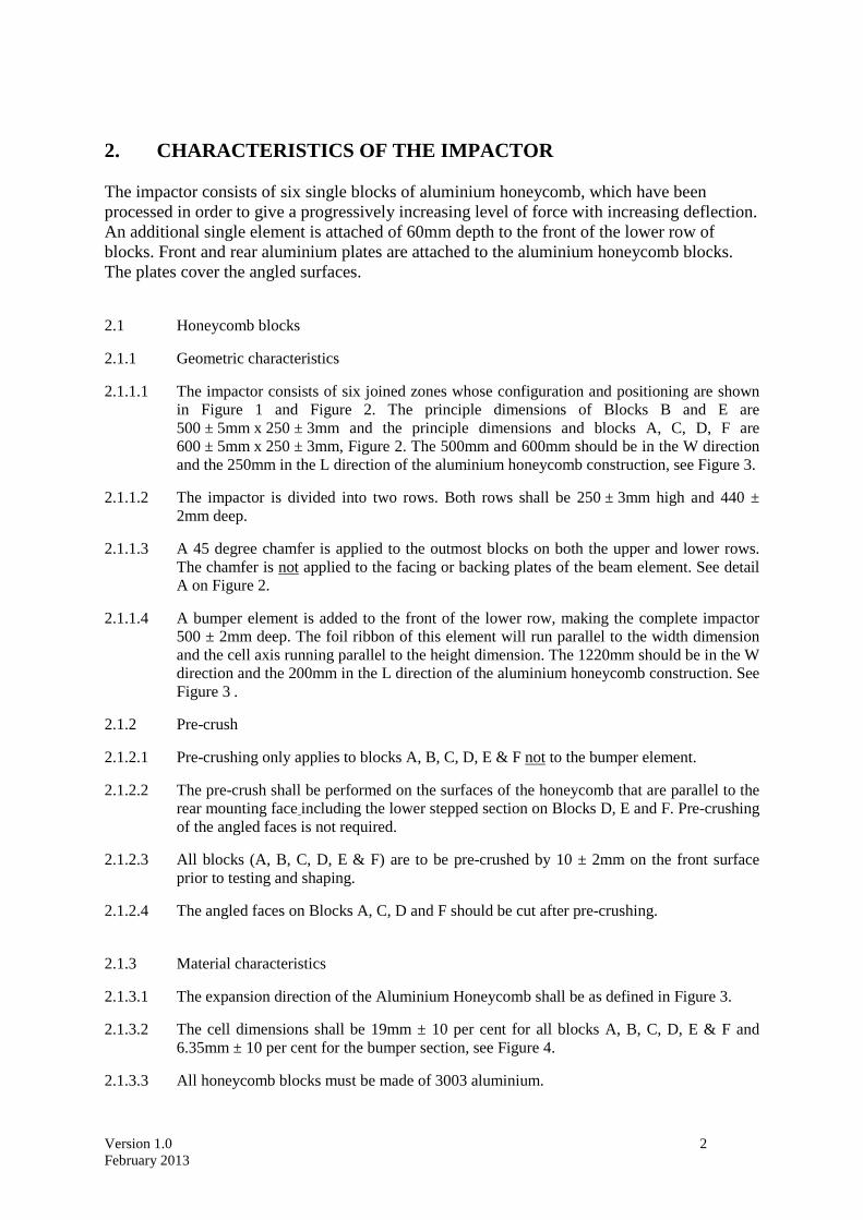
1. CHARACTERISTICS OF THE MOBILE DEFORMABLE BARRIER
1.1 The mobile deformable barrier (MDB) includes both an impactor and a trolley. 1.2 The total mass shall be 1300 ± 20kg. 1.3 The centre of gravity shall be situated in the longitudinal median vertical plane within
10mm, 1000 ± 30mm behind the front axle and 500 ± 30mm above the ground. 1.4 The distance between the front face of the impactor and the centre of gravity of the barrier
shall be 2000 ± 30mm. 1.5 The height of the barrier shall be such that the uppermost part of the front face of the beam
element (the intersection between the upper and lower row of blocks) is 550mm ± 5mm above ground level measured statically prior to impact.
1.6 The front and rear track width of the trolley shall be 1500 ± 10mm. 1.7 The wheelbase of the trolley shall be 3000 ± 10mm.
Version 1.0 2 February 2013
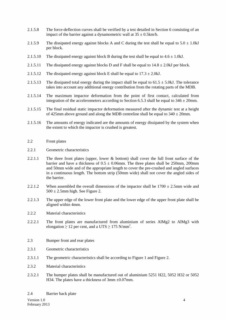
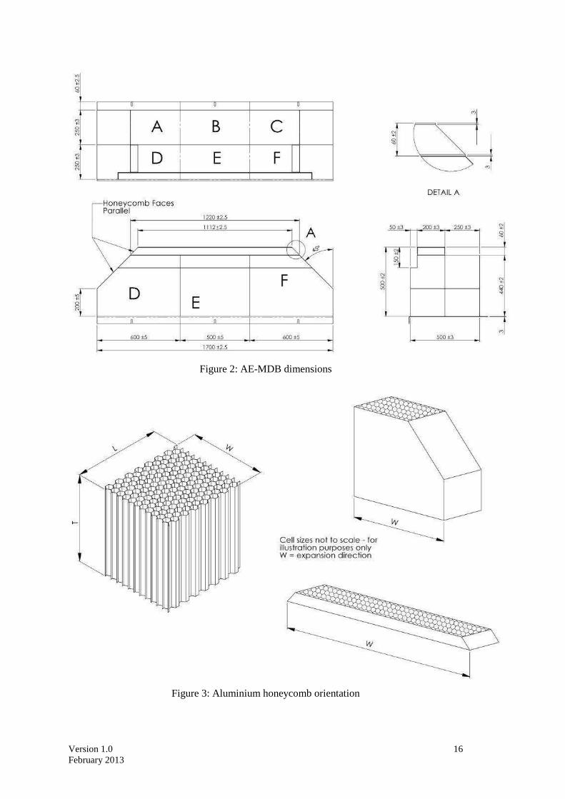
2. CHARACTERISTICS OF THE IMPACTOR The impactor consists of six single blocks of aluminium honeycomb, which have been processed in order to give a progressively increasing level of force with increasing deflection. An additional single element is attached of 60mm depth to the front of the lower row of blocks. Front and rear aluminium plates are attached to the aluminium honeycomb blocks. The plates cover the angled surfaces.
2.1 Honeycomb blocks
2.1.1 Geometric characteristics
2.1.1.1 The impactor consists of six joined zones whose configuration and positioning are shown in Figure 1 and Figure 2. The principle dimensions of Blocks B and E are 500 ± 5mm x 250 ± 3mm and the principle dimensions and blocks A, C, D, F are 600 ± 5mm x 250 ± 3mm, Figure 2. The 500mm and 600mm should be in the W direction and the 250mm in the L direction of the aluminium honeycomb construction, see Figure 3.
2.1.1.2 The impactor is divided into two rows. Both rows shall be 250 ± 3mm high and 440 ± 2mm deep.
2.1.1.3 A 45 degree chamfer is applied to the outmost blocks on both the upper and lower rows. The chamfer is not applied to the facing or backing plates of the beam element. See detail A on Figure 2.
2.1.1.4 A bumper element is added to the front of the lower row, making the complete impactor 500 ± 2mm deep. The foil ribbon of this element will run parallel to the width dimension and the cell axis running parallel to the height dimension. The 1220mm should be in the W direction and the 200mm in the L direction of the aluminium honeycomb construction. See
Figure 3 .
2.1.2 Pre-crush
2.1.2.1 Pre-crushing only applies to blocks A, B, C, D, E & F not to the bumper element.
2.1.2.2 The pre-crush shall be performed on the surfaces of the honeycomb that are parallel to the rear mounting face including the lower stepped section on Blocks D, E and F. Pre-crushing of the angled faces is not required.
2.1.2.3 All blocks (A, B, C, D, E & F) are to be pre-crushed by 10 ± 2mm on the front surface prior to testing and shaping.
2.1.2.4 The angled faces on Blocks A, C, D and F should be cut after pre-crushing.
2.1.3 Material characteristics
2.1.3.1 The expansion direction of the Aluminium Honeycomb shall be as defined in Figure 3.
2.1.3.2 The cell dimensions shall be 19mm ± 10 per cent for all blocks A, B, C, D, E & F and 6.35mm ± 10 per cent for the bumper section, see Figure 4.
2.1.3.3 All honeycomb blocks must be made of 3003 aluminium.

Version 1.0 3 February 2013
2.1.3.4 The aluminium honeycomb blocks (A, B, C, D, E & F) should be processed so that the force deflection-curve when statically crushed (according to the procedure defined in Paragraph 2.1.4) is within corridors to be defined for each of the six blocks in Section 5.
2.1.3.5 The aluminium honeycomb blocks for the bumper element should be processed so that the strength is 1.586 to 1.793MPa when statically crushed (according to the procedure defined in NHTSA TP-214D).
2.1.3.6 The processed honeycomb material used in the honeycomb blocks to be used for construction of the barrier shall be cleaned in order to remove any residue that may have been produced during the processing of the raw honeycomb material.
2.1.3.7 The mass of the blocks in each batch shall not differ by more than 5 per cent of the mean block mass for that batch.
2.1.4 Static tests for all blocks
2.1.4.1 A sample taken from each batch of processed honeycomb core shall be tested according to the static test procedure described in Section 5.
2.1.4.2 The force-deflection characteristic for each block tested shall lie within the force deflection corridors to be defined in Section 8.
2.1.5 Dynamic test
2.1.5.1 The dynamic deformation characteristics, when impacted, shall comply with the procedure described in Section 6.
2.1.5.2 Deviation from the limits of the force-deflection corridors characterising the rigidity of the impactor, as defined in Section 0 may be allowed provided that:
2.1.5.2.1 The deviation occurs after the beginning of the impact and before the deformation of the impactor is equal to 150mm.
2.1.5.2.2 The deviation does not exceed 50 per cent of the nearest instantaneous prescribed limit of the corridor.
2.1.5.2.3 Each deflection corresponding to each deviation does not exceed 35mm of deflection, and the sum of these deflections does not exceed 70mm.
2.1.5.2.4 The sum of energy derived from deviating outside the corridor does not exceed 5 per cent of the gross energy for that block.
2.1.5.3 The dynamic stiffness requirements for Block B is such that the force deflection curve falls between corridors of Section 0, Figure 15.
2.1.5.4 The dynamic stiffness requirements for Blocks A and C are identical. Their rigidity is such that their force deflection curves fall between corridors of Section 0, Figure 16.
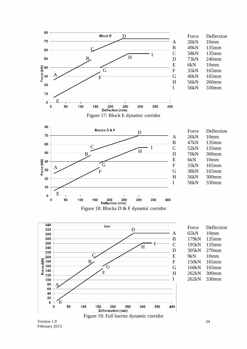
2.1.5.5 The dynamic stiffness requirements for Block E is such that the force deflection curve falls between corridors of Section 0, Figure 17.
2.1.5.6 The dynamic stiffness requirements for Blocks D and F are identical. Their rigidity is such that their force deflection curves fall between corridors of Section 0, Figure 18.
2.1.5.7 The dynamic stiffness requirement for the complete barrier is such that the force deflection curve falls between corridors of Section 0, Figure 19.
Version 1.0 4 February 2013
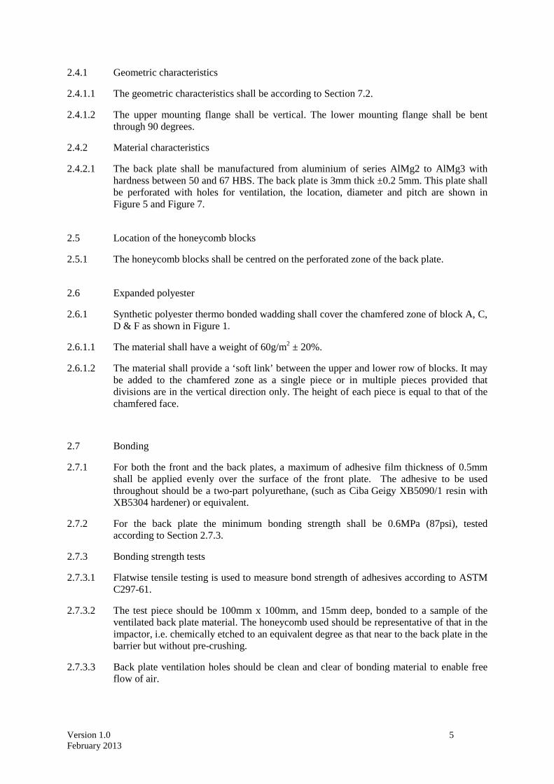
2.1.5.8 The force-deflection curves shall be verified by a test detailed in Section 6 consisting of an impact of the barrier against a dynamometric wall at 35 ± 0.5km/h.
2.1.5.9 The dissipated energy against blocks A and C during the test shall be equal to 5.0 ± 1.0kJ per block.
2.1.5.10 The dissipated energy against block B during the test shall be equal to 4.6 ± 1.0kJ.
2.1.5.11 The dissipated energy against blocks D and F shall be equal to 14.8 ± 2.0kJ per block.
2.1.5.12 The dissipated energy against block E shall be equal to 17.3 ± 2.0kJ.
2.1.5.13 The dissipated total energy during the impact shall be equal to 61.5 ± 5.0kJ. The tolerance takes into account any additional energy contribution from the rotating parts of the MDB.
2.1.5.14 The maximum impactor deformation from the point of first contact, calculated from integration of the accelerometers according to Section 6.5.3 shall be equal to 346 ± 20mm.
2.1.5.15 The final residual static impactor deformation measured after the dynamic test at a height of 425mm above ground and along the MDB centreline shall be equal to 340 ± 20mm.
2.1.5.16 The amounts of energy indicated are the amounts of energy dissipated by the system when the extent to which the impactor is crushed is greatest.
2.2 Front plates
2.2.1 Geometric characteristics
2.2.1.1 The three front plates (upper, lower & bottom) shall cover the full front surface of the barrier and have a thickness of 0.5 ± 0.06mm. The three plates shall be 250mm, 200mm and 50mm wide and of the appropriate length to cover the pre-crushed and angled surfaces in a continuous length. The bottom strip (50mm wide) shall not cover the angled sides of the barrier.
2.2.1.2 When assembled the overall dimensions of the impactor shall be 1700 ± 2.5mm wide and 500 ± 2.5mm high. See Figure 2.
2.2.1.3 The upper edge of the lower front plate and the lower edge of the upper front plate shall be aligned within 4mm.
2.2.2 Material characteristics
2.2.2.1 The front plates are manufactured from aluminium of series AlMg2 to AlMg3 with elongation ≥ 12 per cent, and a UTS ≥ 175 N/mm2.
2.3 Bumper front and rear plates
2.3.1 Geometric characteristics
2.3.1.1 The geometric characteristics shall be according to Figure 1 and Figure 2.
2.3.2 Material characteristics
2.3.2.1 The bumper plates shall be manufactured out of aluminium 5251 H22, 5052 H32 or 5052 H34. The plates have a thickness of 3mm ±0.07mm.
2.4 Barrier back plate
Version 1.0 5 February 2013
2.4.1 Geometric characteristics
2.4.1.1 The geometric characteristics shall be according to Section 7.2.
2.4.1.2 The upper mounting flange shall be vertical. The lower mounting flange shall be bent through 90 degrees.
2.4.2 Material characteristics
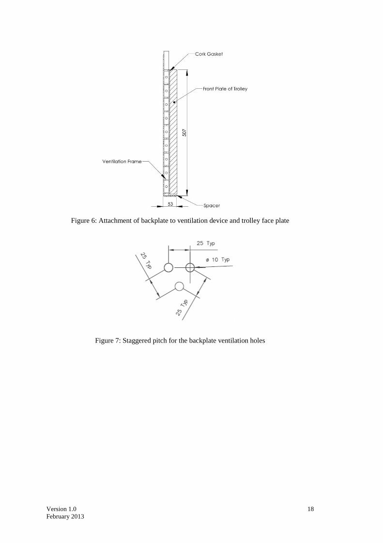
2.4.2.1 The back plate shall be manufactured from aluminium of series AlMg2 to AlMg3 with hardness between 50 and 67 HBS. The back plate is 3mm thick ±0.2 5mm. This plate shall be perforated with holes for ventilation, the location, diameter and pitch are shown in Figure 5 and Figure 7.
2.5 Location of the honeycomb blocks
2.5.1 The honeycomb blocks shall be centred on the perforated zone of the back plate.
2.6 Expanded polyester
2.6.1 Synthetic polyester thermo bonded wadding shall cover the chamfered zone of block A, C, D & F as shown in Figure 1.
2.6.1.1 The material shall have a weight of 60g/m2 ± 20%.
2.6.1.2 The material shall provide a ‘soft link’ between the upper and lower row of blocks. It may be added to the chamfered zone as a single piece or in multiple pieces provided that divisions are in the vertical direction only. The height of each piece is equal to that of the chamfered face.
2.7 Bonding
2.7.1 For both the front and the back plates, a maximum of adhesive film thickness of 0.5mm shall be applied evenly over the surface of the front plate. The adhesive to be used throughout should be a two-part polyurethane, (such as Ciba Geigy XB5090/1 resin with XB5304 hardener) or equivalent.
2.7.2 For the back plate the minimum bonding strength shall be 0.6MPa (87psi), tested according to Section 2.7.3.
2.7.3 Bonding strength tests
2.7.3.1 Flatwise tensile testing is used to measure bond strength of adhesives according to ASTM C297-61.
2.7.3.2 The test piece should be 100mm x 100mm, and 15mm deep, bonded to a sample of the ventilated back plate material. The honeycomb used should be representative of that in the impactor, i.e. chemically etched to an equivalent degree as that near to the back plate in the barrier but without pre-crushing.
2.7.3.3 Back plate ventilation holes should be clean and clear of bonding material to enable free flow of air.

Version 1.0 6 February 2013
2.8 Traceability
2.8.1 Barriers shall carry consecutive serial numbers which are stamped, etched or otherwise permanently attached, from which the batches for the individual blocks and the date of manufacture can be established.
2.9 Impactor attachment
2.9.1 The fitting on the trolley must be according to Figure 8. The fitting will use six M8 bolts, and nothing shall be larger than the dimensions of the barrier in front of the wheels of the trolley. Appropriate spacers must be used between the lower back plate flange and the trolley face to avoid bowing of the back plate when the attachment bolts are tightened.

Version 1.0 7 February 2013
3. VENTILATION SYSTEM
3.1 The interface between the trolley and the ventilation system should be solid, rigid and flat. The ventilation device is part of the trolley and not of the impactor as supplied by the manufacturer. Geometric characteristics of the ventilation device shall be according to Figure 9 and Figure 10.
3.2 Ventilation device mounting procedure
3.2.1 Mount the ventilation device to the front plate of the trolley;
3.2.2 Ensure that a 0.5mm thick feeler gauge cannot be inserted between the ventilation device and the trolley face at any point. If there is a gap greater than 0.5mm, the ventilation frame will need to be replaced or adjusted to fit without a gap of > 0.5mm;
3.2.3 Dismount the ventilation device from the front of the trolley;
3.2.4 Fix a 1mm thick layer of cork to the front face of the trolley;
3.2.5 Re-mount the ventilation device to the front of the trolley and tighten to exclude air gaps.

Version 1.0 8 February 2013
4. CONFORMITY OF PRODUCTION The conformity of production procedures shall comply with those set out in the Agreement, Appendix 2 (E/ECE/324-E/ECE/TRANS/505/Rev.2), with the following requirements:
4.1 The barrier manufacturer shall be responsible for the conformity of production procedures and for that purpose must in particular:
4.1.1 Ensure the existence of effective procedures so that the quality of the products can be inspected;
4.1.2 Have access to the testing equipment needed to inspect the conformity of each product;
4.1.3 Ensure that the test results are recorded and that the documents remain available for a time period of 10 years after testing;
4.1.4 Demonstrate that the samples tested are a reliable measure of the performance of the batch (examples of sampling methods according to batch production are given below);
4.1.5 Analyse results of tests in order to verify and ensure the stability of the barrier characteristics, making allowance for variations of an industrial production, such as temperature, raw materials quality, time of immersion in chemical, chemical concentration, neutralisation etc, and the control of the processed material in order to remove any residue from the processing;
4.1.6 Ensure that any set of samples or test pieces giving evidence of non-conformity gives rise to a further sampling and test. All the necessary steps must be taken to restore conformity of the corresponding production.
4.2 The manufacturer's level of certification must be at least ISO 9001-2008 standard.
4.3 Minimum conditions for the control of production: the holder of an agreement will ensure the control of conformity following the methods hereunder described.
4.4 Examples of sampling according to batch
4.4.1 If several examples of one block type are constructed from one original block of aluminium honeycomb and are all treated in the same treatment bath (parallel production), one of these examples could be chosen as the sample, provided that they are not shaped and care is taken to ensure that the treatment is evenly applied to all blocks. If not, it may be necessary to select more than one sample.
4.4.2 If a limited number of similar blocks (say three to twenty) are treated in the same bath (serial production), then the first and last block treated in a batch, all of which are constructed from the same original block of aluminium honeycomb, should be taken as representative samples. If the first sample complies with the requirements but the last does not, it may be necessary to take further samples from earlier in the production until a sample that does comply is found. Only the blocks between these samples should be considered to be approved. All samples must remain unshaped.
4.4.3 Once experience is gained with the consistency of production control, it may be possible to combine both sampling approaches, so that more than one groups of parallel production can be considered to be a batch provided samples from the first and last production groups comply.

Version 1.0 9 February 2013
5. STATIC TESTS
5.1 One or more samples (according to the batch method) taken from each batch of processed honeycomb core shall be tested, according to the following test procedure:
5.1.1 The samples for all blocks (A, B, C, D, E and F) shall be 250mm x 500mm x 440mm.
5.1.2 The samples should be compressed between two parallel loading plates which are at least 20mm larger that the block cross section;
5.1.3 The compression speed shall be 100 millimetres per minute, with a tolerance of 5 per cent;
5.1.4 The data acquisition for static compression shall be sampled at a minimum of 5Hz;
5.1.5 The static test shall be continued until the block compression is at least 300mm for all blocks (A, B, C, D, E and F);
Version 1.0 10 February 2013
6. DYNAMIC LOAD CELL WALL TESTS For every 200 barrier faces produced, the manufacturer shall make one dynamic test against a dynamometric wall supported by a fixed rigid barrier, according to the method described below.
6.1 Installation
6.1.1 Testing ground
6.1.1.1 The test area shall be large enough to accommodate the run-up-track of the mobile deformable barrier, the rigid barrier and the technical equipment necessary for the test. The last part of the track, for at least five metres before the rigid barrier, shall be horizontal, flat and smooth.
6.1.1.2 Fixed rigid barrier and dynamometric wall
6.1.1.3 The rigid wall shall consist of a block of reinforced concrete not less than 3 metres wide and not less than 1.5 metres high. The thickness of the rigid wall shall be such that it weighs at least 70 tonnes.
6.1.1.4 The front face shall be vertical, perpendicular to the axis of the run-up-tack and equipped with a minimum of six load cell plates, each capable of measuring the total load on the appropriate block of the mobile deformable barrier impactor at the moment of impact. The load cell impact plate area centres shall align with those of the six impact zones of the mobile deformable barrier face. Their edges shall clear adjacent areas by 20mm ± 2mm such that, within the tolerance of impact alignment of the MDB, the impact zones will not contact the adjacent impact plate areas. Cell mounting and plate surfaces shall be in accordance with the requirements set out in the annex to standard ISO 6487:1987.
6.1.1.5 The load cell wall must consist of at least 6 load cells, with the centre load cell having a loading surface area 500mm wide and 250mm high, and the outer load cells, covering Blocks A, C, D and F, having a loading surface area 600mm wide and 250mm high. If more than six load cells are used the aggregated area must be 500mm by 250mm at the centre and 600mm by 250mm outside.
6.1.1.6 The area surrounding the load cells (<1700mm by <500mm) must have a surface common to that of the load cell wall face for at least 150mm (>2000mm by >800mm). This is required to ensure that the barrier face is uniformly crushed and does not wrap around the edge of the load cells if the barrier impact is not in perfect alignment.
6.1.1.7 Surface protection, comprising a plywood face with a thickness of 18mm ± 5mm shall be added to each load cell plate such that no degradation of transducer responses occurs.
6.1.1.8 The rigid wall shall be either anchored in the ground or placed on the ground with, if necessary, additional arresting devices to limit its deflection. A rigid wall (to which the load cells are attached) having different characteristics but giving results that are at least equally conclusive may be used.
6.1.1.9 The load cells must align with the principle axes of the MDB face with Blocks B and E aligned with the central load cells. The intersection of all blocks must align with intersections between load cells.
6.2 Propulsion of the mobile deformable barrier
Version 1.0 11 February 2013
6.2.1 At the moment of impact the mobile deformable barrier shall no longer be subject to the action of any additional steering or propelling device. It shall reach the obstacle on a course perpendicular to the front surface of the dynamometric wall. The impact alignment shall be accurate to within ± 15mm.
6.3 Measuring instruments
6.3.1 Speed
6.3.1.1 The impact speed shall be 35 ± 0.5km/h the instrument used to record the speed on impact shall be accurate to within 0.1 percent.
6.3.2 Loads
6.3.2.1 Measuring instruments shall meet the specifications set forth in ISO 6487:1987 CFC for all blocks: 60Hz CAC for all blocks: 100kN
6.3.3 Acceleration
6.3.3.1 The acceleration in the longitudinal direction shall be measured at three separate positions on the trolley, one centrally and one at each side, at places not subject to bending.
6.3.3.2 The central accelerometer shall be located within 500mm of the location of the centre of gravity of the MDB and shall lie in a vertical longitudinal plane which is within ± 10mm of the centre of gravity of the MDB.
6.3.3.3 The side accelerometers shall be at the same height as each other ± 10mm and at the same distance from the front surface of the MDB ± 20mm
6.3.3.4 The instrumentation shall comply with ISO 6487:1987 with the following specifications: CFC 1,000Hz (before integration) CAC 50g
6.3.4 Contact timing
6.3.4.1 Two foil contact switches shall be fitted at the outboard ends of the face of the beam element which contact the load cell wall first.
6.3.4.2 The contact switches must have a depth of 3mm or less.
6.4 General specifications of barrier and impactor
6.4.1 The individual characteristics of each mobile deformable barrier shall comply with Section 1 of this specification and shall be recorded.
6.4.2 The suitability of an impactor as regards to the dynamic test requirements shall be confirmed when the outputs from the six load cell plates each produce signals complying with the requirements indicated in this specification.

Version 1.0 12 February 2013
6.4.3 Impactors shall carry consecutive serial numbers which are stamped, etched or otherwise permanently attached, from which the batches for the individual blocks and the date of manufacture can be established.
6.5 Data processing procedure
6.5.1 Raw data
6.5.1.1 At time T = T0, all offsets should be removed from the data. The method by which offsets are removed shall be recorded in the test report.
6.5.1.2 T0 shall be established using the two contact switches fitted to the beam element.
6.5.2 Filtering
6.5.2.1 The raw data will be filtered prior to processing/calculations.
6.5.2.2 Accelerometer data for integration will be filtered to CFC 180, ISO 6487:1987.
6.5.2.3 Accelerometer data for impulse calculations will be filtered to CFC 60, ISO 6487:1987.
6.5.2.4 Load cell data will be filtered to CFC 60, ISO 6487:1987.
6.5.3 Calculation of MDB face deflection
6.5.3.1 Accelerometer data from all three accelerometers individually (after filtering at CFC 180), will be integrated twice to obtain deflection of the barrier deformable element.
6.5.3.2 The initial conditions for deflection are:
6.5.3.2.1 Velocity = impact velocity (from speed measuring device);
6.5.3.2.2 Deflection = 0;
6.5.3.3 The deflection at the left hand side, mid-line and right hand side of the mobile deformable barrier will be plotted with respect to time.
6.5.3.4 The maximum deflection calculated from each of the three accelerometers should be within 10mm. If it is not the case, then the outlier should be removed and difference between the deflection calculated from the remaining two accelerometers checked to ensure that it is within 10mm.
6.5.3.5 If the deflections as measured by the left hand side, right hand side and mid-line accelerometers are within 10mm, then the mean acceleration of the three accelerometers should be used to calculate the deflection of the barrier face.
6.5.3.6 If the deflection from only two accelerometers meets the 10mm requirement, then the mean acceleration from these two accelerometers should be used to calculate the deflection for the barrier face.
6.5.3.7 If the deflections calculated from all three accelerometers (left hand side, right hand side and mid-line) are NOT within the 10mm requirement, then the raw data should be reviewed to determine the causes of such large variation. In this case the individual test house will determine which accelerometer data should be used to determine mobile deformable barrier deflection or whether none of the accelerometer readings can be used,
Version 1.0 13 February 2013
in which case, the certification test must be repeated. A full explanation should be given in the test report.
6.5.3.8 T0 will be defined for both force and acceleration data using the two contact switches placed on the beam element. Due to the effects of filtering, it is expected that force levels at T0 will be above 0kN for the lower row of blocks. Force data must NOT be shifted to establish 0kN at T0.
6.5.3.9 The mean deflection-time data will be combined with the load cell wall force-time data to generate the force-deflection result for each block.
6.5.4 Calculation of energy
6.5.4.1 The absorbed energy for each block and for the whole MDB face should be calculated up to the point of peak deflection of the barrier.
∫= 1
0
.t
t meannn dsFE
where: t0 is the time of first contact t1 is the time where the trolley comes to rest, i.e. where u = 0. s is the deflection of the trolley deformable element calculated according
to Paragraph 6.5.3.
6.5.5 Verification of dynamic force data
6.5.5.1 Compare the total impulse, I, calculated from the integration of the total force over the period of contact, with the momentum change over that period (M*∆V).
6.5.5.2 Compare the total energy change to the change in kinetic energy of the MDB, given by:
2
21
iK MVE =
where: Vi is the impact velocity
M the whole mass of the MDB
6.5.5.3 If the momentum change (M*∆V) is not equal to the total impulse (I) ± 5 per cent, or if the total energy absorbed (Ε En) is not equal to the kinetic energy, EK ± 5 per cent, then the test data must be examined to determine the cause of this error.
6.6 Post test
6.6.1 The crush of the AE-MDB should be recorded after the LCW impact at a representative point on the barrier. The crush measurement shall be compared to the deflection calculated from the trolley accelerometer data. If the calculated deflection is 20mm or more below the crush measured after the impact, the individual test house will determine if any of the

Version 1.0 14 February 2013
accelerometer data can be used, in which case, the certification test must be repeated. A full explanation should be given in the test report.
Version 1.0 15 February 2013
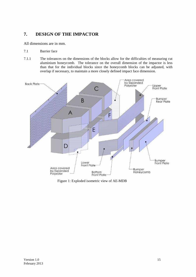
7. DESIGN OF THE IMPACTOR All dimensions are in mm.
7.1 Barrier face
7.1.1 The tolerances on the dimensions of the blocks allow for the difficulties of measuring cut aluminium honeycomb. The tolerance on the overall dimension of the impactor is less than that for the individual blocks since the honeycomb blocks can be adjusted, with overlap if necessary, to maintain a more closely defined impact face dimension.
Figure 1: Exploded isometric view of AE-MDB
Version 1.0 16 February 2013
Figure 2: AE-MDB dimensions
Figure 3: Aluminium honeycomb orientation

Version 1.0 17 February 2013
Figure 4: Dimension of Aluminium Honeycomb Cells
7.2 Back plate
Figure 5: Rear view of the back of the barrier face
19mm ±1.9mm
6.35mm ±0.7mm
Version 1.0 18 February 2013
Figure 6: Attachment of backplate to ventilation device and trolley face plate
Figure 7: Staggered pitch for the backplate ventilation holes

Version 1.0 19 February 2013
7.2.1 Top and bottom back plate flanges
7.2.2 The attachment holes in the bottom flange may be opened to slots, as shown below, for ease of attachment provided sufficient grip can be developed to avoid detachment during the whole impact test.
Figure 8: Top and bottom AE-MDB mounting flanges
7.3 Ventilation frame
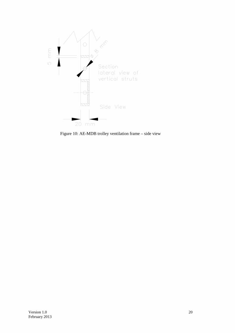
7.3.1 The ventilation device is a structure made of a plate that is 5mm thick and 20mm wide. Only the vertical plates are perforated with nine 8mm holes in order to let air circulate horizontally.
7.3.2 It is acceptable for ventilation frames that are 1500mm in with to be extended up to 1700mm in width provided that the correct pattern of venting and fixation is used.
Figure 9: AE-MDB trolley ventilation frame
Version 1.0 20 February 2013
Figure 10: AE-MDB trolley ventilation frame – side view

Version 1.0 21 February 2013
8. STATIC FORCE DEFLECTION CORRIDORS Force deflection corridors for quasi-static crush tests to test samples measuring 250 x 500mm for all blocks.
Figure 11: Block B static corridor
Figure 12: Blocks A & C static corridor
A
Force Deflection A 3.8kN 6mm B 20kN 240mm C 0kN 11mm D 16kN 240mm
A
B
C
D
Force Deflection A 3.9kN 6mm B 18kN 240mm C 0kN 11mm D 14kN 240mm
A
B
C
D

Version 1.0 22 February 2013
Figure 13: Block E static corridor
Figure 14: Blocks D & F static corridor
Force Deflection A 22.2kN 6mm B 38.8kN 83mm C 51.5kN 210mm D 10kN 10mm E 31.5kN 110mm F 41.5kN 210mm
A
B
E
C
D
F
Force Deflection A 19kN 6mm B 41.5kN 95mm C 9.5kN 10mm D 32.5kN 100mm
A
B
C
D

Version 1.0 23 February 2013
9. DYNAMIC FORCE DEFLECTION CORRIDORS Force deflection corridors for dynamic barrier to LCW tests.
Figure 15: Block B dynamic corridor
Figure 16: Blocks A & C dynamic corridor
Force Deflection A 7kN 50mm B 33kN 300mm C 2kN 80mm D 23kN 300mm E 23kN 330mm
Force Deflection A 7kN 60mm B 14kN 130mm C 38kN 300mm D 0kN 74mm E 6kN 130mm F 28kN 300mm G 28kN 330mm
A
B
C
D E
A
B
C
D E
F G
Version 1.0 24 February 2013
Figure 17: Block E dynamic corridor
Figure 18: Blocks D & F dynamic corridor
Figure 19: Full barrier dynamic corridor
Force Deflection A 65kN 10mm B 179kN 135mm C 195kN 135mm D 305kN 270mm E 9kN 10mm F 150kN 165mm G 160kN 165mm H 262kN 300mm I 262kN 330mm
Force Deflection A 26kN 10mm B 47kN 135mm C 52kN 135mm D 70kN 300mm E 6kN 10mm F 33kN 165mm G 38kN 165mm H 56kN 300mm I 56kN 330mm
A
B
C
D
E
F G
H I
A
B C
D
E
F G
H I
Force Deflection A 26kN 10mm B 49kN 135mm C 58kN 135mm D 73kN 240mm E 6kN 10mm F 35kN 165mm G 40kN 165mm H 56kN 260mm I 56kN 330mm
A
B
C
D
E
F
G
H I

Version 1.0 25 February 2013