Technical Analysis of Ligado Interference Impact on ... Aviation... · Technical Analysis of Ligado...
19
Technical Analysis of Ligado Interference Impact on Iridium Aviation Services December 14, 2016 REDACTED – FOR PUBLIC INSPECTION REDACTED – FOR PUBLIC INSPECTION
Transcript of Technical Analysis of Ligado Interference Impact on ... Aviation... · Technical Analysis of Ligado...
Technical Analysis of Ligado Interference Impact on Iridium Aviation Services
December 14, 2016
REDACTED – FOR PUBLIC INSPECTION
REDACTED – FOR PUBLIC INSPECTION

Table of Contents
1 Background ............................................................................................................................. 1
2 Iridium SATCOM Aviation Services ..................................................................................... 1
3 Ligado Interference Description ............................................................................................. 2
3.1 Ligado Interference Characteristics ................................................................................. 2
3.2 Ligado Interference to Iridium is Distinct from GPS ....................................................... 3
4 Ligado Interference Analysis Assumption, Methodology and Scenario Descriptions ........... 3
4.1 Analysis Assumptions ...................................................................................................... 3
4.1.1 Single Ligado User Terminal Emissions .................................................................. 4
4.1.2 Aggregate Ligado User Terminal Emissions ............................................................ 5
4.1.3 Iridium User Terminal Receiver Characteristics ...................................................... 6
4.1.4 Signal Propagation Models ....................................................................................... 7
4.2 Interference Scenarios ...................................................................................................... 9
4.2.1 Helicopter and Aircraft Take Off/Landing Aggregate Interference Scenario ........ 10
4.2.2 Same Aircraft Interference Scenario ....................................................................... 11
4.2.3 Airport Terminal Gate Interference Scenario ......................................................... 12
5 Detailed Interference Analysis .............................................................................................. 12
5.1 Helicopter and Aircraft Take Off/Landing Interference Results ................................... 12
5.2 Same Aircraft Interference Results ................................................................................ 15
5.3 Airport Terminal Gate Interference Results ................................................................... 16
6 Summary of Findings ............................................................................................................ 17
REDACTED – FOR PUBLIC INSPECTION
REDACTED – FOR PUBLIC INSPECTION
1 Background The Federal Communications Commission has requested comment on Ligado’s proposed out-of-band emissions (OOBE) limits1 as described in Ligado’s modification applications for its L-band ancillary terrestrial component (ATC) terminals and base stations.2 Iridium has separately provided a technical analysis of Ligado user terminal interference into Iridium terminals with respect to general terrestrial environments.3 In a subsequent filing with the Commission, Ligado attempted to refute the methodology and results of Iridium’s analysis.4 Iridium has subsequently demonstrated5 that Ligado’s critique of the Iridium Technical Analysis is based on invalid assumptions and does not alter Iridium’s original analysis. Thus, much of the analysis assumptions and methodologies used in the corresponding terrestrial analysis are also applicable to the aeronautical case, as described in section 4 below. The technical analysis herein provides an assessment of the harmful interference Ligado’s proposed emissions will cause to Iridium aviation services in particular. Iridium currently has a robust aeronautical market, including both Aeronautical Operational Communications (AOC) and Aeronautical Mobile (Route) Satellite Service (AMS(R)S) capabilities. This analysis leverages the corresponding terrestrial interference analyses and applies them to Iridium aeronautical terminal scenarios.
2 Iridium SATCOM Aviation Services Iridium provides pole-to-pole, true global mobile satellite services through a constellation architecture of 66 satellites in low earth orbit. Since the system was launched in the late 1990s as primarily a provider of voice call services, it has evolved to provide a suite of data, two-way messaging, broadcast messaging, netted push-to-talk and broadband services across a wide range of terrestrial, maritime and aviation markets. Iridium’s services will be significantly enhanced by Iridium’s second generation system, Iridium NEXT, which was recently licensed by the FCC6 and is scheduled to begin launching replacement satellites in the near future. Iridium NEXT will
1 Comment Sought on Ligado’s Modification Applications, Public Notice, DA 16-442 (rel. Apr. 22, 2016). 2 See Applications of LightSquared Subsidiary LLC, IBFS File Nos. SAT-MOD-20151231-00090, SAT-MOD-20151231-00091, and SES-MOD-20151231-0098; Letter from Gerard J. Waldron, Counsel to New LightSquared LLC, to Marlene H. Dortch, Secretary, FCC, IB Docket Nos. 12-340 and 11-109 (filed Dec. 31, 2015). 3 Technical Analysis of Ligado Interference Impact on Iridium User Links (Sept. 1, 2016) (“Technical Analysis”) (attached to Letter from Bryan N. Tramont, Counsel, Iridium, to Marlene H. Dortch, Secretary, FCC, IB Docket Nos. 11-109 and 12-340 (filed Sept. 1, 2016)). 4 See generally Letter from Gerard J. Waldron. Counsel to Ligado, to Marlene H. Dortch, Secretary, FCC, IB Docket Nos. 11-109 and 12-340 (filed Nov. 2, 2016) (“Ligado Technical Analysis”). 5 See generally Letter from Bryan N. Tramont, Counsel to Iridium, to Marlene H. Dortch, Secretary, FCC, IB Docket Nos. 11-109 and 12-340 (filed Dec. 14, 2016). 6 Iridium Constellation LLC, Application for Modification of License to Authorize a Second-Generation NGSO MSS Constellation, File Nos. SAT-MOD-20131227-00148, SAT-AMD-20151022-00074, Order and Authorization (rel. August 1, 2016).
REDACTED – FOR PUBLIC INSPECTION
REDACTED – FOR PUBLIC INSPECTION
2
support all legacy services and user equipment while also delivering higher data rate services for all Iridium users, including aviation services. Iridium SATCOM aviation services are vital to the operations of over 55,000 subscribers in the air transport, rotorcraft, business aviation, and general aviation services. This represents approximately 30,000 aircraft. Iridium currently has over 60% of the mobile satellite aviation market share. Iridium systems are deployed on major carriers like United Airlines and JetBlue, in thousands of rotorcraft, and in as many as 10,000 business jets. As noted above, Iridium SATCOM aviation services include both AOC, which provides vital operator datalink services to aircraft of all types, and AMS(R)S, which provides safety critical datalink services for air traffic control, among others. The SATCOM datalink services provided by Iridium enable communications between ground facilities and the plane. In conjunction with VHF datalink, SATCOM datalink helps planes communicate with airports before landing and provides connectivity throughout the flight for safety updates and adjustments to the flight plan. Iridium’s SATCOM datalink ensures connection to the ground where there are gaps in terrestrial systems and at smaller airports without VHF systems. SATCOM datalink also provides air transport pilots with weight and balance information, gate assignments, and other important data that is no longer transmitted by hand or by voice communications. Along with several domestic airlines, the UPS fleet of jets is dependent on Iridium’s datalink technology. For example, interference with Iridium receivers at the UPS Worldport in Louisville, Kentucky, could ground UPS flights and endanger timely delivery services across the country, including for items such as critical medical supplies or other emergency deliveries. Iridium is also the only proven satellite technology for rotorcraft connectivity in-flight. Iridium supports thousands of helicopters, offering flight path and safety information and tracking. Its users include providers of medical evacuation services, fire and rescue teams, Forest Service firefighters, police helicopters, border control, oil and gas companies, and wind farms. For private planes in the general aviation services, Iridium provides the connectivity that enables real-time information to be relayed to pilots and to the planes’ flight controls. This includes weather updates, which are vital for small aircraft flying below cloud level. Iridium services also enable small aircraft pilots to call ahead to airports, enabling safe landing. Beyond its immediate practical consequences, the possibility of interference from Ligado may prevent airlines from relying on Iridium systems as part of their connectivity solutions. Ligado interference could therefore put the FAA’s future domestic SATCOM plan at risk, setting the FAA back years in achieving its goal of making the domestic airspace more efficient.
3 Ligado Interference Description
3.1 Ligado Interference Characteristics Ligado’s modification applications provide proposed operational characteristics for ATC base stations and mobile user terminals. Ligado’s proposed operation of user terminals in the 1627.5-1637.5 MHz band, which is immediately adjacent to Iridium’s operations in the 1617.775-1626.5 MHz band, will produce harmful interference to Iridium end users. In some cases, the interference is so severe that Iridium services would be [BEGIN CONFIDENTIAL]
[END CONFIDENTIAL] Ligado’s use
REDACTED – FOR PUBLIC INSPECTION
REDACTED – FOR PUBLIC INSPECTION
3
of user terminals at 1646.5-1656.5 MHz does not create any interference issues for Iridium customers. The potential for Ligado’s proposed operations to cause significant interference into Iridium user terminals manifests itself in two major ways:
• OOBE within Iridium’s frequency band would significantly inhibit Iridium communications; and
• Millions of ubiquitously deployed ATC and/or terrestrial-only LTE or 5G user terminals would greatly increase the probability of these terminals operating near an Iridium terminal.
All Iridium user terminals transmit and receive in the 1617.775-1626.5 MHz band.7 Ligado has proposed an OOBE mask that, while purportedly affording protection for some GPS receivers, does not sufficiently protect Iridium receivers in the immediately adjacent band. In the upper portion of Iridium’s band, this OOBE mask has emission levels [BEGIN CONFIDENTIAL]
[END CONFIDENTIAL] Given that a single Ligado user terminal would produce such harmful levels of interference, the number, density and proximity to Iridium terminals all play a major role in assessing aggregate interference into Iridium terminals.
3.2 Ligado Interference to Iridium is Distinct from GPS The potential for Ligado ATC interference into GPS receivers has been studied exhaustively for many years. Much (if not most) of these analyses have focused on the “proximity” scenario of a Ligado terrestrial base station or user terminal, in close proximity to a GPS receiver, producing in-band emissions that overload the GPS receiver front end. Though Ligado OOBE into the GPS receiver has also been studied, significant concerns remain about GPS receiver overload due to GPS receiver selectivity in Ligado’s transmit bands. In contrast to the GPS interference problem, Ligado OOBE within Iridium’s band produce interference severe enough to significantly impact Iridium services and is not only an issue when a Ligado terminal is in close proximity to an Iridium user terminal. While overload of Iridium receiver front ends may result from large numbers of transmitting Ligado terminals in close proximity to an Iridium terminal, the more impactful interference scenario studied in this report is due to Ligado’s OOBE alone.
4 Ligado Interference Analysis Assumption, Methodology and Scenario Descriptions
4.1 Analysis Assumptions This report provides an assessment of Ligado user terminal interference on Iridium aviation services, while leveraging interference scenario assumptions used in Iridium’s corresponding
7 Iridium is currently licensed to use this band, but the Iridium system supports transmit and receive in the 1616.0-1626.5 MHz band, and on multiple occasions has been granted STAs to use this extended spectrum to support emergency relief efforts around the world.
REDACTED – FOR PUBLIC INSPECTION
REDACTED – FOR PUBLIC INSPECTION
4
terrestrial interference assessment report as well as in Ligado-to-GPS interference assessments in RTCA SC-159 and Commerce Spectrum Management Advisory Committee (CSMAC) Working Group 1 (“WG-1”) studies.
4.1.1 Single Ligado User Terminal Emissions The foundation for all interference scenarios in this report is based on the individual Ligado user terminal OOBE characteristics. These are provided in Ligado’s modification applications and summarized here. Ligado user terminals are proposed to have an in-band equivalent isotropically radiated power (EIRP) value of -7 dBW in the 1627.5-1637.5 MHz band. The OOBE mask for these terminals is described as:
• Limit of -34 dBW/MHz between 1625 and 1626.5 MHz; and
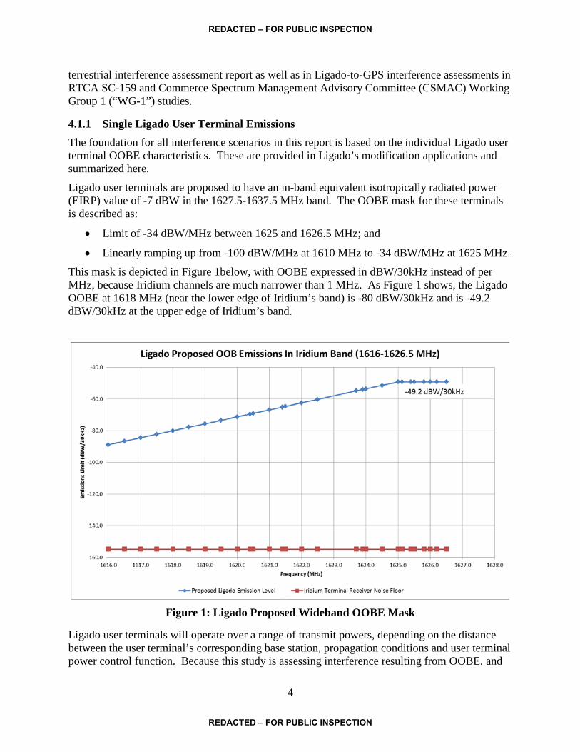
• Linearly ramping up from -100 dBW/MHz at 1610 MHz to -34 dBW/MHz at 1625 MHz. This mask is depicted in Figure 1below, with OOBE expressed in dBW/30kHz instead of per MHz, because Iridium channels are much narrower than 1 MHz. As Figure 1 shows, the Ligado OOBE at 1618 MHz (near the lower edge of Iridium’s band) is -80 dBW/30kHz and is -49.2 dBW/30kHz at the upper edge of Iridium’s band.
Figure 1: Ligado Proposed Wideband OOBE Mask
Ligado user terminals will operate over a range of transmit powers, depending on the distance between the user terminal’s corresponding base station, propagation conditions and user terminal power control function. Because this study is assessing interference resulting from OOBE, and
REDACTED – FOR PUBLIC INSPECTION
REDACTED – FOR PUBLIC INSPECTION
5
not receiver overload due to Ligado in-band emissions, Ligado’s proposed OOBE limits are used in this study.
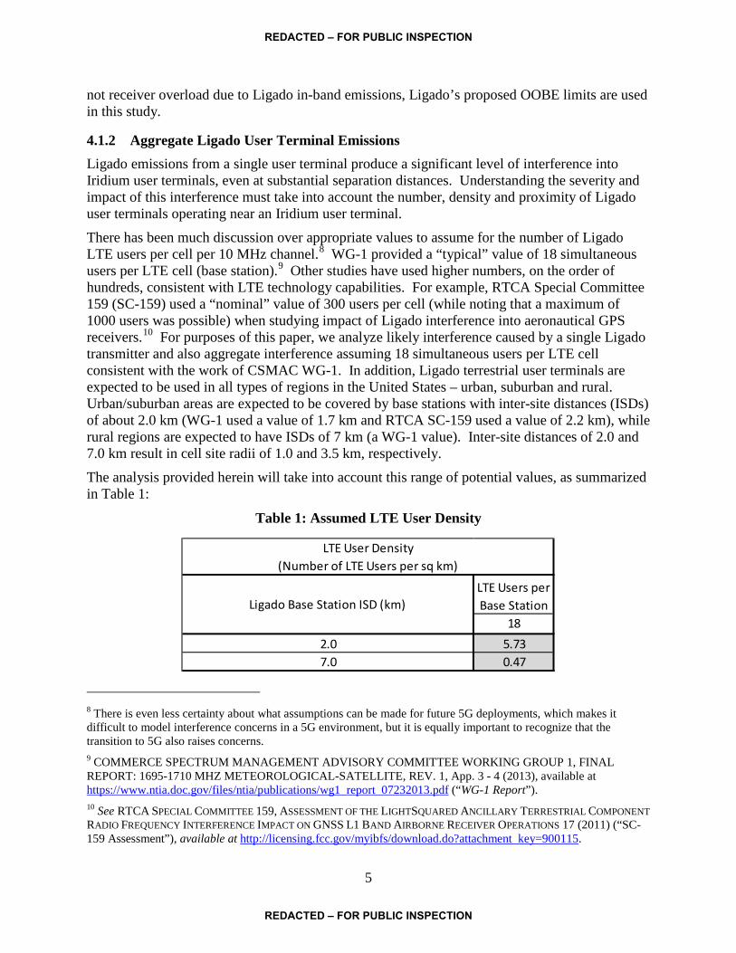
4.1.2 Aggregate Ligado User Terminal Emissions Ligado emissions from a single user terminal produce a significant level of interference into Iridium user terminals, even at substantial separation distances. Understanding the severity and impact of this interference must take into account the number, density and proximity of Ligado user terminals operating near an Iridium user terminal. There has been much discussion over appropriate values to assume for the number of Ligado LTE users per cell per 10 MHz channel.8 WG-1 provided a “typical” value of 18 simultaneous users per LTE cell (base station).9 Other studies have used higher numbers, on the order of hundreds, consistent with LTE technology capabilities. For example, RTCA Special Committee 159 (SC-159) used a “nominal” value of 300 users per cell (while noting that a maximum of 1000 users was possible) when studying impact of Ligado interference into aeronautical GPS receivers.10 For purposes of this paper, we analyze likely interference caused by a single Ligado transmitter and also aggregate interference assuming 18 simultaneous users per LTE cell consistent with the work of CSMAC WG-1. In addition, Ligado terrestrial user terminals are expected to be used in all types of regions in the United States – urban, suburban and rural. Urban/suburban areas are expected to be covered by base stations with inter-site distances (ISDs) of about 2.0 km (WG-1 used a value of 1.7 km and RTCA SC-159 used a value of 2.2 km), while rural regions are expected to have ISDs of 7 km (a WG-1 value). Inter-site distances of 2.0 and 7.0 km result in cell site radii of 1.0 and 3.5 km, respectively. The analysis provided herein will take into account this range of potential values, as summarized in Table 1:
Table 1: Assumed LTE User Density
8 There is even less certainty about what assumptions can be made for future 5G deployments, which makes it difficult to model interference concerns in a 5G environment, but it is equally important to recognize that the transition to 5G also raises concerns. 9 COMMERCE SPECTRUM MANAGEMENT ADVISORY COMMITTEE WORKING GROUP 1, FINAL REPORT: 1695-1710 MHZ METEOROLOGICAL-SATELLITE, REV. 1, App. 3 - 4 (2013), available at https://www.ntia.doc.gov/files/ntia/publications/wg1 report 07232013.pdf (“WG-1 Report”). 10 See RTCA SPECIAL COMMITTEE 159, ASSESSMENT OF THE LIGHTSQUARED ANCILLARY TERRESTRIAL COMPONENT RADIO FREQUENCY INTERFERENCE IMPACT ON GNSS L1 BAND AIRBORNE RECEIVER OPERATIONS 17 (2011) (“SC-159 Assessment”), available at http://licensing.fcc.gov/myibfs/download.do?attachment key=900115.
LTE Users per Base Station
182.0 5.737.0 0.47
LTE User Density (Number of LTE Users per sq km)
Ligado Base Station ISD (km)
REDACTED – FOR PUBLIC INSPECTION
REDACTED – FOR PUBLIC INSPECTION

6
4.1.3 Iridium User Terminal Receiver Characteristics Assessing Iridium user terminal vulnerability to interference is predicated on the user terminal receiver noise floor and antenna pattern and user deployment characteristics. Iridium user terminals are represented by various product lines supporting a variety of mobile satellite services, including circuit switched voice and data, data messaging, paging, netted (push-to-talk) communications and broadband communications. The receiver performance across these terminal types, however, may be characterized by a common receiver noise floor, equivalent to -199.6 dBW/Hz. The fundamental Iridium channelization is based on channel spacing of 41.7 kHz, with an occupied bandwidth of 33.5 kHz (irrespective of Doppler shift). Therefore, noise measurement bandwidths of 30 kHz are appropriate for assessing Iridium receiver performance, since this standard measurement bandwidth is similar to the bandwidth of an Iridium channel. The user terminal noise floor of -199.6 dBW/Hz converts to a per 30 kHz value of -154.8 dBW/30kHz, which is the limit against which Ligado interference will be assessed. Accordingly, interference analyses in this study will be provided in terms of interference to noise (I/N) ratio. The aggregate interference threshold for Iridium transceivers used in this report is I/N = -6 dB (∆T/T = 25%), or an interference level that results in a decrease in link margin of 1 dB. I/N = -6 dB is a typical value chosen in interference studies,11 but usually in studies where same services (e.g., FSS to FSS) or different services (e.g., FSS to FS) are sharing a common frequency band. In fact, the Iridium system design specification assumes a single entry interference criterion of I/N = -12.2 dB (∆T/T = 6%). In situations like the one being studied here, an out-of-band interferer like Ligado is often subject to an interference threshold of I/N = -20 dB (∆T/T = 1%).12 Nevertheless, an I/N = -6 dB will be assumed for the aggregate interference from Ligado terminals. In fact, the RTCA DO-270 Aviation System Performance Standard for Iridium services uses this value for the interference protection criterion as well. Iridium user terminals also support a variety of different antenna technologies and forms, but all are generally low gain, hemispherical pattern antennas having gain of unity (0 dBi), averaged over the distribution of elevation angles to the nearest satellite. As a low earth orbiting (LEO) satellite constellation, Iridium’s users may be communicating with the nearest satellite at any given azimuth, at any given elevation angle down to 8 degrees, at any given point in time anywhere on earth. As a result, Iridium user equipment must have antennas that can “see” the entire sky. An Iridium aeronautical terminal antenna can be expected to have a typical gain of about -6 dBi at small elevation angles below horizon towards the interfering Ligado terminal, while having peak gain of 3 dBi at higher elevation angles. A gain of -6 dBi is used in this analysis. Since the interference is assumed to be received into the Iridium antenna sidelobes, no cross-polarization isolation is assumed, since cross-polarization is typically accounted for in main-beam-to-main-beam scenarios.
11 See, e.g., Int’l Telecomm. Union [ITU], Recommendation S.1432, available at https://www.itu.int/rec/R-REC-S.1432/en; see also SC-159 Assessment, supra note 10, Executive Summary (also using a 1 dB increase in noise floor criteria). 12 See, e.g., ITU Recommendation S.1432, supra note 11.
REDACTED – FOR PUBLIC INSPECTION
REDACTED – FOR PUBLIC INSPECTION

7
Ligado’s proposed OOBE levels vary within the Iridium band. Iridium user services are not segmented within the Iridium band, other than the upper 500 kHz (1626.0-1626.5 MHz), which is a downlink only band used for Iridium broadcast messaging transmissions [BEGIN CONFIDENTIAL]
[END CONFIDENTIAL] The rest of Iridium’s band is
used uniformly for uplink and downlink transmissions for all Iridium services. The particular frequency channel used by an Iridium terminal, for transmit or receive, is directed by the Iridium satellite and is not selectable by the Iridium user terminal. Furthermore, the Iridium user may be handed off to other frequency channels at any point during a transaction due to the dynamic movement of the satellites and corresponding satellite beams on the Earth’s surface. The last assumption to consider for Iridium transceivers is that these transceivers need to be operating in duplex mode throughout a given communications session in order to maintain the link with the satellite. Regardless of whether communications are only being sent on the uplink or received on the downlink or in both directions, link maintenance signaling information is continuously being transferred between the user terminal and satellite for all of these cases. For example, when an Iridium user sets up an M2M data session in order to originate data for transmission to the network, that user’s receiver must be operational during the entire session to maintain the link, even if no data is being delivered to the user on the downlink. This is important when assessing the impact of interference into the Iridium user device’s receiver; protection of the user terminal receiver is critical to maintaining the communications path.
4.1.4 Signal Propagation Models This study assumes multiple propagation models, depending on the interference scenario. For the scenario of multiple Ligado user terminals transmitting near an airport where an Iridium-equipped aircraft is taking off or landing, two models are used: free space path loss, appropriate for short, line-of-sight separation distances between interfering terminals; and the Hata-Okumura terrestrial propagation model, often used in land mobile applications. While much work has been done in previous Ligado user terminal interference studies attempting to choose appropriate signal propagation models across a range of interference scenarios, no clear consensus exists as to which model is the most appropriate. This study seeks to simplify the analysis such that general conclusions may be drawn. The free space path loss (FSPL) is described by the following well-known expression,13 where d is the separation distance in meters and f is the carrier frequency in hertz:
FSPL (dB) = 20log(d) + 20log(f) – 147.55 Because this model assumes line-of-sight between the interfering Ligado terminal and victim Iridium terminal receiver, this model is applicable for separation distances less than or equal to
13 See, e.g., Revision of Part 15 of the Commission’s Rules Regarding Operation in the 57-64 GHz Band, Report and Order, 28 FCC Rcd 12517, 12533 n.103 (2013).
REDACTED – FOR PUBLIC INSPECTION
REDACTED – FOR PUBLIC INSPECTION

8
100 meters. RTCA SC-159 also considered it appropriate when an aircraft victim receiver is at altitudes above 550 meters, relative to a terrestrial Ligado user terminal interferer. The Hata-Okumura median path propagation path loss model is used in this report for modeling losses for horizontal distances greater than 1000 meters and for aircraft altitudes less than 500 meters.14 The Ligado Technical Analysis states that use of the Hata-Okumura model is not appropriate for analyzing interference between Ligado and Iridium user terminals in urban areas and prefers use of the Walfisch-Ikegami Non-Line-of-Sight (WI-NLOS) model, which results in much higher propagation losses and accounts for in-building attenuation.15 However, both WG-1 and SC-159 both deemed this type of model inappropriate for these types of interference scenarios.16 Because the FSPL model has greater validity for separation distances on the order of 100 meters and less, while the Hata-Okumura model has greater validity for separation distances greater than 1,000 meters, path losses in the range 100 to 1,000 meters were extrapolated between the two models and included with the Hata-Okumura model. A graphical representation of these models is shown in Figure 2 below. For the same-aircraft interference scenario, data for the path loss from inside an aircraft cabin to the external Iridium antenna is derived from other sources, as described below in section 4.2.2. For the airport terminal interference scenario, in which Ligado users are in the terminal gate area adjacent to the Iridium-equipped aircraft, the FSPL model is used for these short separation distances, but with an additional 20 dB of attenuation due to exterior airport wall or window blockage, as described in section 4.2.3 below.
14 The model used in this report is identical to the model used by RTCA SC-159 in their report on LightSquared interference into GPS. See SC-159 Assessment, at 46 & App. B at B-6. 15 Ligado Technical Analysis at 5. 16 See e.g. WG-1 Report at App. 7 (“Since these models particularly overestimate propagation loss at small time percentages, they are not appropriate for interference calculations.”).
REDACTED – FOR PUBLIC INSPECTION
REDACTED – FOR PUBLIC INSPECTION

9
Figure 2: Comparison of Propagation Path Loss Models Used in this Analysis
4.2 Interference Scenarios Three different scenarios for Ligado interference into Iridium aviation service are assessed. At a high level, those scenarios are:
• Surrounding area aggregate Ligado user terminal interference into Iridium aeronautical terminals installed on rotorcraft. This same interference analysis applies to Iridium aeronautical terminals installed on aircraft while any Iridium-equipped aircraft (fixed or rotary wing) is flying at relatively low altitude or taking off or landing at an airport;
• Interference from Ligado user terminals from passengers on commercial aircraft to the Iridium terminal equipment installed on the same aircraft; and
• Surrounding area aggregate Ligado user terminal interference into Iridium aeronautical terminals while the Iridium-equipped aircraft is at the terminal gate.
The methodology for each scenario is described below.
REDACTED – FOR PUBLIC INSPECTION
REDACTED – FOR PUBLIC INSPECTION
10
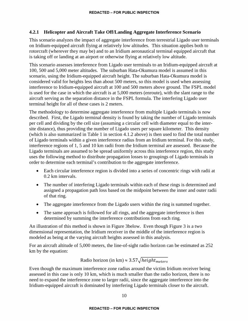
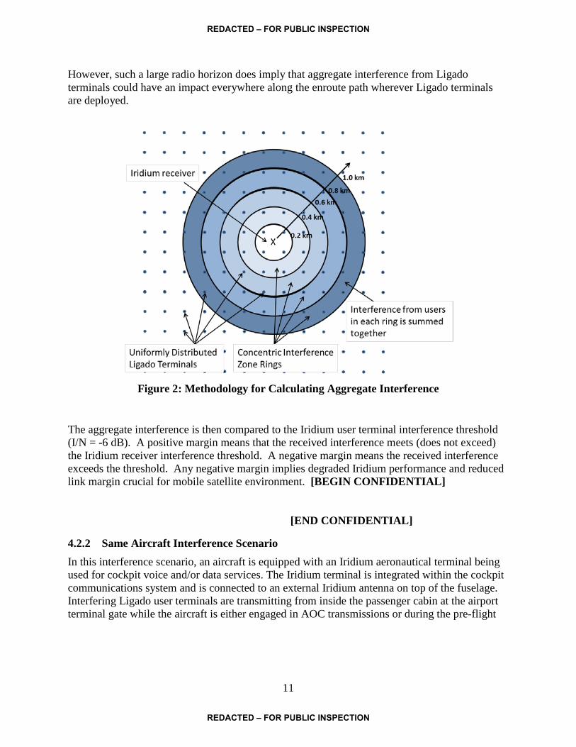
4.2.1 Helicopter and Aircraft Take Off/Landing Aggregate Interference Scenario This scenario analyzes the impact of aggregate interference from terrestrial Ligado user terminals on Iridium-equipped aircraft flying at relatively low altitudes. This situation applies both to rotorcraft (wherever they may be) and to an Iridium aeronautical terminal equipped aircraft that is taking off or landing at an airport or otherwise flying at relatively low altitude. This scenario assesses interference from Ligado user terminals to an Iridium-equipped aircraft at 100, 500 and 5,000 meter altitudes. The suburban Hata-Okumura model is assumed in this scenario, using the Iridium-equipped aircraft height. The suburban Hata-Okumura model is considered valid for heights less than about 500 meters, so this model is used when assessing interference to Iridium-equipped aircraft at 100 and 500 meters above ground. The FSPL model is used for the case in which the aircraft is at 5,000 meters (enroute), with the slant range to the aircraft serving as the separation distance in the FSPL formula. The interfering Ligado user terminal height for all of these cases is 2 meters. The methodology to determine aggregate interference from multiple Ligado terminals is now described. First, the Ligado terminal density is found by taking the number of Ligado terminals per cell and dividing by the cell size (assuming a circular cell with diameter equal to the inter-site distance), thus providing the number of Ligado users per square kilometer. This density (which is also summarized in Table 1 in section 4.1.2 above) is then used to find the total number of Ligado terminals within a given interference radius from an Iridium terminal. For this study, interference regions of 1, 5 and 10 km radii from the Iridium terminal are assessed. Because the Ligado terminals are assumed to be spread uniformly across this interference region, this study uses the following method to distribute propagation losses to groupings of Ligado terminals in order to determine each terminal’s contribution to the aggregate interference.
• Each circular interference region is divided into a series of concentric rings with radii at 0.2 km intervals.
• The number of interfering Ligado terminals within each of these rings is determined and assigned a propagation path loss based on the midpoint between the inner and outer radii of that ring.
• The aggregate interference from the Ligado users within the ring is summed together.
• The same approach is followed for all rings, and the aggregate interference is then determined by summing the interference contributions from each ring.
An illustration of this method is shown in Figure 3below. Even though Figure 3 is a two dimensional representation, the Iridium receiver in the middle of the interference region is modeled as being at the varying aircraft heights assessed in this analysis. For an aircraft altitude of 5,000 meters, the line-of-sight radio horizon can be estimated as 252 km by the equation:
Radio horizon (in km) ≈ 3.57�ℎ𝑒𝑒𝑒ℎ𝑡𝑚𝑚𝑚𝑚𝑚𝑚
Even though the maximum interference zone radius around the victim Iridium receiver being assessed in this case is only 10 km, which is much smaller than the radio horizon, there is no need to expand the interference zone to larger radii, since the aggregate interference into the Iridium-equipped aircraft is dominated by interfering Ligado terminals closer to the aircraft.
REDACTED – FOR PUBLIC INSPECTION
REDACTED – FOR PUBLIC INSPECTION
11
However, such a large radio horizon does imply that aggregate interference from Ligado terminals could have an impact everywhere along the enroute path wherever Ligado terminals are deployed.
Figure 2: Methodology for Calculating Aggregate Interference
The aggregate interference is then compared to the Iridium user terminal interference threshold (I/N = -6 dB). A positive margin means that the received interference meets (does not exceed) the Iridium receiver interference threshold. A negative margin means the received interference exceeds the threshold. Any negative margin implies degraded Iridium performance and reduced link margin crucial for mobile satellite environment. [BEGIN CONFIDENTIAL]
[END CONFIDENTIAL]
4.2.2 Same Aircraft Interference Scenario In this interference scenario, an aircraft is equipped with an Iridium aeronautical terminal being used for cockpit voice and/or data services. The Iridium terminal is integrated within the cockpit communications system and is connected to an external Iridium antenna on top of the fuselage. Interfering Ligado user terminals are transmitting from inside the passenger cabin at the airport terminal gate while the aircraft is either engaged in AOC transmissions or during the pre-flight
REDACTED – FOR PUBLIC INSPECTION
REDACTED – FOR PUBLIC INSPECTION
12
AMS(R)S system check.17 Clearly, if Ligado terminals are active during a flight (regardless of whether they are explicitly permitted or not), the same interference situation exists. For this same aircraft scenario, the FSPL and Hata-Okumura propagation models are not applicable. However, research on simulation and actual measurements of propagation loss for this type of situation can be found in the literature and RTCA SC-202 studies.18 The referenced paper provides path loss measurements for radio signals at L1 GPS frequencies transmitting at various locations within the passenger cabin for a range of different commercial aircraft and measured at an external antenna location on the aircraft fuselage. Path loss measurements for Boeing 737 and 747 aircraft, used by multiple Iridium customers including United and UPS, showed minimum path losses of 64 and 65 dB, respectively; 65 dB is used in this analysis. Since the frequencies of interest in this study (Iridium’s L-band spectrum around 1620 MHz) are very similar to the GPS L1 frequency (1575.42 MHz), the path loss is assumed to be the same for both sets of frequencies.
4.2.3 Airport Terminal Gate Interference Scenario This scenario analyzes the impact of interference from Ligado user terminals within an airport terminal, but near an Iridium-equipped aircraft parked at the gate that is either engaged in AOC transmissions or going through a pre-flight AMS(R)S system check. Users from within the airport will have their transmissions attenuated by airport building structures. Measurements of L-band propagation attenuation through building materials are described in the literature. One such reference19 provides simulated and measured path losses of GPS L1 signals of about 17 dB for reinforced concrete and about 24 dB for tinted glass, with much smaller attenuations for other materials. This study assumes a nominal attenuation of 20 dB for Ligado users within the airport terminal, in addition to the free space path loss between the terminal and Iridium-equipped aircraft, at a separation distance of 100 meters.
5 Detailed Interference Analysis Interference results for each of the three Iridium aviation scenarios are provided in the subsections below.
5.1 Helicopter and Aircraft Take Off/Landing Interference Results Results for aggregate interference from Ligado user terminals on rotorcraft (wherever they may be) or on Iridium-equipped aircraft while taking off or landing near an airport are shown below. Two sets of interference assessments are shown for low density and high density deployments of Ligado terminals, as explained in section 4.2.1 above. The interference assessments for this scenario are for Iridium-equipped aircraft at 100, 500 and 5,000 meter altitudes. For the
17 Pre-flight system check typically involves establishing an Iridium voice/data connection while at the gate to verify successful system operation. If this pre-flight check fails, delay and/or cancellation of the flight may be required. 18 “Path Loss from a Transmitter Inside an Aircraft Cabin to an Exterior Fuselage-Mounted Antenna” IEEE Transactions on Electromagnetic Compatibility, vol. 50, No. 3, August 2008. 19 “GNSS Indoors Fighting the Fading, Part 2,” www.insidegnss.com, May/June 2008.
REDACTED – FOR PUBLIC INSPECTION
REDACTED – FOR PUBLIC INSPECTION

13
relatively low altitudes of 100 and 500 meters, this aggregate interference scenario is expected to be similar to interference scenarios in which an Iridium terminal is onboard a helicopter, since helicopters tend to fly at lower altitudes. As described in section 4.2.1, Ligado interference to the Iridium-equipped aircraft at low altitudes of 100 and 500 meters is modeled assuming the more lossy Hata-Okumura propagation model. For aircraft altitude of 5,000 meters, the interference is assessed using the FSPL model.
[BEGIN CONFIDENTIAL] Table 2: Low Altitude Aircraft Take Off/Landing and Helicopter Aggregate Interference
Results (Low Density Ligado User Terminals)
Table 3: Low Altitude Aircraft Take Off/Landing and Helicopter Aggregate Interference Results (High Density Ligado User Terminals)
[END CONFIDENTIAL]
Ligado user terminal OOBE limit -49.2 -49.2 -49.2 -49.2 -49.2 -49.2 dBW/30kHzFrequency 1626.5 1626.5 1626.5 1626.5 1626.5 1626.5 MHzInterference radius from Iridium user 1.0 5.0 10.0 1.0 5.0 10.0 kmLigado users per cell 18.0 18.0 18.0 18.0 18.0 18.0Ligado cell radius 3.5 3.5 3.5 3.5 3.5 3.5 km
Number of Ligado users within interference radius 1.5 36.7 146.9 1.5 36.7 146.9Aircraft height 100.0 100.0 100.0 500.0 500.0 500.0 metersWeighted average path loss dB Iridium receiver antenna gain at horizon -6.0 -6.0 -6.0 -6.0 -6.0 -6.0 dBi
Aggregate received interference power density dBW/30kHzIridium user terminal noise floor -154.8 -154.8 -154.8 -154.8 -154.8 -154.8 dBW/30kHzI/N dBRequired I/N -6 -6 -6 -6 -6 -6 dBMargin dB
Ligado user terminal OOBE limit -49.2 -49.2 -49.2 -49.2 -49.2 -49.2 dBW/30kHzFrequency 1626.5 1626.5 1626.5 1626.5 1626.5 1626.5 MHzInterference radius from Iridium user 1.0 5.0 10.0 1.0 5.0 10.0 kmLigado users per cell 18.0 18.0 18.0 18.0 18.0 18.0Ligado cell radius 1.0 1.0 1.0 1.0 1.0 1.0 km
Number of Ligado users within interference radius 18.0 450.0 1800.0 18.0 450.0 1800.0Aircraft height 100.0 100.0 100.0 500.0 500.0 500.0 metersWeighted average path loss per user dB Iridium receiver antenna gain -6.0 -6.0 -6.0 -6.0 -6.0 -6.0 dBiAggregate received interference power density dBW/30kHzIridium user terminal noise floor -154.8 -154.8 -154.8 -154.8 -154.8 -154.8 dBW/30kHzI/N dBRequired I/N -6 -6 -6 -6 -6 -6 dBMargin dB
REDACTED – FOR PUBLIC INSPECTION
REDACTED – FOR PUBLIC INSPECTION

14
At low altitudes, Tables 2 and 3 reveal that aggregate emissions from surrounding Ligado terminals produce interference [BEGIN CONFIDENTIAL]
[END CONFIDENTIAL] for both Ligado terminal densities. Even low density deployment of Ligado terminals produces interference that exceeds the protection criteria by [BEGIN CONFIDENTIAL] [END CONFIDENTIAL] As expected, high density Ligado terminal deployments produce significant levels of interference, at levels that exceed the protection criteria by [BEGIN CONFIDENTIAL]
[END CONFIDENTIAL] Aggregate interference for each deployment case reveals higher interference when the aircraft is at the higher altitude of 500 meters, which shows how important the victim receiver height is in the Hata-Okumura propagation model. Results for interference into mid-altitude Iridium-equipped aircraft (5,000 meters) are shown in Tables 4 and 5, for low density and high density Ligado terminal deployments.
[BEGIN CONFIDENTIAL] Table 4: Medium Altitude Aircraft Take Off/Landing Aggregate Interference Results (Low
Density Ligado User Terminals)
[END CONFIDENTIAL]
Ligado user terminal OOBE limit -49.2 -49.2 dBW/30kHzFrequency 1626.5 1626.5 MHzInterference radius from Iridium user 5.0 10.0 kmLigado users per cell 18.0 18.0Ligado cell radius 3.5 3.5 km
Number of Ligado users within interference radius 36.7 146.9Aircraft height 5000.0 5000.0 metersWeighted average path loss dB Iridium receiver antenna gain at horizon -6.0 -6.0 dBi
Aggregate received interference power density dBW/30kHzIridium user terminal noise floor -154.8 -154.8 dBW/30kHzI/N dBRequired I/N -6 -6 dBMargin dB
REDACTED – FOR PUBLIC INSPECTION
REDACTED – FOR PUBLIC INSPECTION

15
[BEGIN CONFIDENTIAL] Table 5: Medium Altitude Aircraft Take Off/Landing Aggregate Interference Results
(High Density Ligado User Terminals)
[END CONFIDENTIAL] Once again, results show that even at medium aircraft altitudes, there is significant Ligado terminal interference exceeding Iridium terminal protection criteria during critical aircraft enroute paths.
5.2 Same Aircraft Interference Results Table 6 below shows interference results from a single Ligado terminal within a commercial airliner into the Iridium aeronautical terminal antenna on top of the fuselage. The path loss for this scenario, as described in section 4.2.2 above, is representative of a Boeing 747 aircraft. The results show that even a single Ligado terminal produces an [BEGIN CONFIDENTIAL]
[END CONFIDENTIAL] level of interference into the Iridium receiver, exceeding the interference protection criteria by [BEGIN CONFIDENTIAL] [END CONFIDENTIAL] Such an interference level would [BEGIN CONFIDENTIAL]
[END CONFIDENTIAL] Under such conditions, the Iridium terminal may be [BEGIN CONFIDENTIAL]
[END CONFIDENTIAL]
Ligado user terminal OOBE limit -49.2 -49.2 dBW/30kHzFrequency 1626.5 1626.5 MHzInterference radius from Iridium user 5.0 10.0 kmLigado users per cell 18.0 18.0Ligado cell radius 1.0 1.0 km
Number of Ligado users within interference radius 450.0 1800.0Aircraft height 5000 5000 metersWeighted average path loss per user dB Iridium receiver antenna gain -6.0 -6.0 dBiAggregate received interference power density dBW/30kHzIridium user terminal noise floor -154.8 -154.8 dBW/30kHzI/N dBRequired I/N -6 -6 dBMargin dB
REDACTED – FOR PUBLIC INSPECTION
REDACTED – FOR PUBLIC INSPECTION

16
[BEGIN CONFIDENTIAL]
Table 6: Same Aircraft, Single Ligado Terminal Interference Results
[END CONFIDENTIAL] Again, this excessive level of interference is the result from a single Ligado user terminal on the aircraft and would obviously be worsened by multiple Ligado users on the aircraft.
5.3 Airport Terminal Gate Interference Results The results for Ligado terminals within an airport terminal near the gate at which an Iridium-equipped aircraft is parked, is shown below in Table 7. A single Ligado user terminal located at the terminal gate at which an Iridium-equipped commercial jet is parked, produces interference exceeding the Iridium protection criteria by [BEGIN CONFIDENTIAL] [END CONFIDENTIAL] which would likely be enough to [BEGIN CONFIDENTIAL]
[END CONFIDENTIAL] The results are also provided for the
case of five Ligado terminals at or near the gate, producing an additional aggregate interference level of [BEGIN CONFIDENTIAL] [END CONFIDENTIAL] resulting in interference levels exceeding protection criteria by [BEGIN CONFIDENTIAL] [END CONFIDENTIAL]
Single Ligado user terminal OOBE limit -49.2 dBW/30kHzFrequency 1626.5 MHzPath loss dB Iridium receiver antenna gain at horizon -3.0 dBiReceived interference power density dBW/30kHzIridium user terminal noise floor -154.8 dBW/30kHzI/N dBRequired I/N -6 dBMargin dB
REDACTED – FOR PUBLIC INSPECTION
REDACTED – FOR PUBLIC INSPECTION

17
[BEGIN CONFIDENTIAL]
Table 7: Airport Terminal Gate Interference Results
[END CONFIDENTIAL]
6 Summary of Findings Three very different scenarios assessing Ligado terminal interference to Iridium aeronautical terminals have been investigated in this appendix. Whether considering Ligado user terminal emissions from within the same aircraft, or Ligado emissions from within the airport or aggregate Ligado emissions from the surrounding area, victim Iridium aeronautical terminals receive interference that [BEGIN CONFIDENTIAL]
[END CONFIDENTIAL] These excessive levels of interference would be sufficient to [BEGIN CONFIDENTIAL]
[END
CONFIDENTIAL] Interference from Ligado terminals in any location served by Ligado base stations has the potential to produce severe interference to Iridium-equipped rotorcraft as well.
Ligado user terminal OOBE limit -49.2 -49.2 dBW/30kHz
Frequency 1626.5 1626.5 MHzSeparation distance between Ligado user terminal and Iridium-equipped aircraft 100.0 100.0 mLigado users in airport terminal within 100 m of Iridium-equipped aircraft 1.0 5.0Free space path loss at 100 m 76.6 76.6 dBAdditional airport structure attenuation 20.0 20.0 dB
Iridium receiver antenna gain at horizon -3.0 -3.0 dBiAggregate received interference power density dBW/30kHzIridium user terminal noise floor -154.8 -154.8 dBW/30kHzI/N dBRequired I/N -6 -6 dBMargin dB
REDACTED – FOR PUBLIC INSPECTION
REDACTED – FOR PUBLIC INSPECTION