TECH SPEC - Brown's Concrete Products Limited · This dome of heat traps dust and gases ......
12
Concrete Grid Pavements Background As cities grow, man-made surfaces contribute to urban heat and stormwater runoff. Heat is generated by the high concentration of pavements and buildings. It forms a dome of warm air, or an urban heat island, over cities that can be as much as 12° F (7°C) higher than outlying areas. The urban heat island also inceases electricity consumption for air conditioning. This dome of heat traps dust and gases, increasing the concentrations of air pollution from automobile exhaust and industrial sources (1). A high concentration of pavements and buildings, or impervious surfaces, generates additional runoff during rainstorms. Washed from the air and pavements, excess runoff carries pollutants that enter water courses. The runoff generated by impervious surfaces erodes streams, degenerating riparian environments, and pollutes sources of drinking water. Increased runoff volumes and veloci- ties deprive ground water from recharging, decreasing the amount of available water in many communities. Concrete grid pavements or “green parking lots” originated from the need to reduce the urban heat island and stormwater runoff from impervious surfaces. Perforated concrete units as pavement were introduced when hollow concrete building blocks were placed in the ground to support cars. They first appeared in 1961 to handle overflow parking at a major cultural center near Stuttgart, Germany (2). They were a replacement for temporary steel runway matting. Figure 1 shows the genesis of grids. Since then, concrete grids developed in Europe were applied in North America as a method for reducing lake- side and streambank erosion, as well as for ditch liners. Concrete grids were later used for driveways, main and overflow parking areas, shoulders along airfields and highways crossovers on medians, boat launching ramps, emergency fire lanes and for access roads adjacent to buildings. See Figure 2. Figures 3-13 illustrate many uses of concrete grid pavers. This technical bulletin provides guidance on the design, specification, construction, and maintenance of concrete grid pavements for a wide © 1999 ICPI Tech Spec No. 8 • Interlocking Concrete Pavement Institute • All rights reserved—Revised April 2006 range of applications. Concrete grids are an environmen- tally friendly technology that can help earn credits under green building rating systems such as LEED ® and Green Globes. For more information on how grids can earn cred- its see ICPI Tech Spec 16 – Achieving LEED ® Credits with Segmental Concrete Pavement. Properties of Concrete Grid Paving Units The properties of concrete grid units are defined in ASTM C 1319, Standard Specification for Concrete Grid Paving Units (3). This specification defines concrete grids as having maximum dimensions of 24 in. long by 24 in. wide (610 mm by 610 mm) and a minimum nominal thick- ness of 3 1 /8 in. (80 mm). The minimum required thickness of the webs between the openings is 1 in. (25 mm). Dimensional tolerances should not dif- fer from approved sam- ples more than 1 /8 in. (3.2 mm) for length, width, and height. The minimum com- pressive strength of the concrete grid units should average 5,000 psi (35 MPa) with no individual one less than 4,500 psi (31 Mpa). Their average water absorption should not exceed 10 lb/ft 3 (160 kg/m 3 ). Freeze-thaw dura- bility is based on three Figure 1. Grids first used in Germany in 1961 for overflow parking were building blocks placed in the ground. They emerged from the need to cool cit- ies and decrease stormwa- ter runoff. Figure 2. A typical grid pavement for occasional vehicular traffic TECH SPEC NUMBER 8
Transcript of TECH SPEC - Brown's Concrete Products Limited · This dome of heat traps dust and gases ......
Concrete Grid PavementsBackgroundAs cities grow, man-made surfaces contribute to urban heat and stormwater runoff. Heat is generated by the high concentration of pavements and buildings. It forms a dome of warm air, or an urban heat island, over cities that can be as much as 12° F (7°C) higher than outlying areas. The urban heat island also inceases electricity consumption for air conditioning. This dome of heat traps dust and gases, increasing the concentrations of air pollution from automobile exhaust and industrial sources (1).
A high concentration of pavements and buildings, or impervious surfaces, generates additional runoff during rainstorms. Washed from the air and pavements, excess runoff carries pollutants that enter water courses. The runoff generated by impervious surfaces erodes streams, degenerating riparian environments, and pollutes sources of drinking water. Increased runoff volumes and veloci-ties deprive ground water from recharging, decreasing the amount of available water in many communities.
Concrete grid pavements or “green parking lots” originated from the need to reduce the urban heat island and stormwater runoff from impervious surfaces. Perforated concrete units as pavement were introduced when hollow concrete building blocks were placed in the ground to support cars. They first appeared in 1961 to handle overflow parking at a major cultural center near Stuttgart, Germany (2). They were a replacement for temporary steel runway matting. Figure 1 shows the genesis of grids.
Since then, concrete grids developed in Europe were applied in North America as a method for reducing lake-side and streambank erosion, as well as for ditch liners. Concrete grids were later used for driveways, main and overflow parking areas, shoulders along airfields and highways crossovers on medians, boat launching ramps, emergency fire lanes and for access roads adjacent to buildings. See Figure 2. Figures 3-13 illustrate many uses of concrete grid pavers. This technical bulletin provides guidance on the design, specification, construction, and maintenance of concrete grid pavements for a wide
© 1999 ICPI Tech Spec No. 8 • Interlocking Concrete Pavement Institute • All rights reserved—Revised April 2006
range of applications. Concrete grids are an environmen-tally friendly technology that can help earn credits under green building rating systems such as LEED® and Green Globes. For more information on how grids can earn cred-its see ICPI Tech Spec 16 – Achieving LEED® Credits with Segmental Concrete Pavement.
Properties of Concrete Grid Paving UnitsThe properties of concrete grid units are defined in ASTM C 1319, Standard Specification for Concrete Grid Paving Units (3). This specification defines concrete grids as having maximum dimensions of 24 in. long by 24 in. wide (610 mm by 610 mm) and a minimum nominal thick-ness of 31/8 in. (80 mm). The minimum required thickness of the webs between the openings is 1 in. (25 mm). Dimensional tolerances should not dif-fer from approved sam-ples more than 1/8 in. (3.2 mm) for length, width, and height.
The minimum com-pressive strength of the concrete grid units should average 5,000 psi (35 MPa) with no individual one less than 4,500 psi (31 Mpa). Their average water absorption should not exceed 10 lb/ft3 (160 kg/m3). Freeze-thaw dura-bility is based on three
Figure 1. Grids first used in Germany in 1961 for overflow parking were building blocks placed in the ground. They emerged from the need to cool cit-ies and decrease stormwa-ter runoff.
Figure 2. A typical grid pavement for occasional vehicular traffic
T E C H S P E C
N u m b E r 8
ICPI Tech Spec 8 Page 2
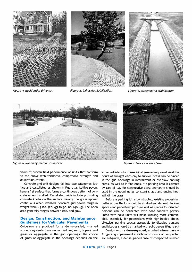
Figure 3. Residential driveway Figure 4. Lakeside stabilization Figure 5. Streambank stabilization
Figure 6. Roadway median crossover Figure 7. Service access lane
years of proven field performance of units that conform to the above web thickness, compressive strength and absorption criteria.
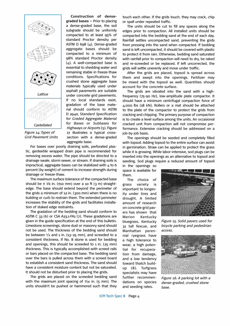
Concrete grid unit designs fall into two categories: lat-tice and castellated as shown in Figure 14. Lattice pavers have a flat surface that forms a continuous pattern of con-crete when installed. Castellated grids include protruding concrete knobs on the surface making the grass appear continuous when installed. Concrete grid pavers range in weight from 45 lbs. (20 kg) to 90 lbs. (40 kg). The open area generally ranges between 20% and 50%.
Design, Construction, and Maintenance Guidelines for Vehicular PavementsGuidelines are provided for a dense-graded, crushed stone, aggregate base under bedding sand, topsoil and grass or aggregate in the grid openings. The choice of grass or aggregate in the openings depends on the
expected intensity of use. Most grasses require at least five hours of sunlight each day to survive. Grass can be placed in the grid openings in intermittent or overflow parking areas, as well as in fire lanes. If a parking area is covered by cars all day for consecutive days, aggregate should be used in the openings as constant shade and engine heat will kill the grass.
Before a parking lot is constructed, existing pedestrian paths across the lot should be studied and defined. Parking spaces and pedestrian paths as well as spaces for disabled persons can be delineated with solid concrete pavers. Paths with solid units will make walking more comfort-able, especially for pedestrians with high-heeled shoes. Likewise, parking spaces accessible to disabled persons and bicycles should be marked with solid pavers (Figure 15).
Design with a dense-graded, crushed stone base — A typical grid pavement installation consists of compacted soil subgrade, a dense-graded base of compacted crushed
ICPI Tech Spec 8 Page 3
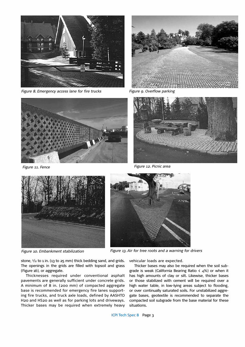
Figure 8. Emergency access lane for fire trucks Figure 9. Overflow parking
Figure 10. Embankment stabilization
Figure 11. Fence Figure 12. Picnic area
Figure 13. Air for tree roots and a warning for drivers
stone, 1/2 to 1 in. (13 to 25 mm) thick bedding sand, and grids. The openings in the grids are filled with topsoil and grass (Figure 16), or aggregate.
Thicknesses required under conventional asphalt pavements are generally sufficient under concrete grids. A minimum of 8 in. (200 mm) of compacted aggregate base is recommended for emergency fire lanes support-ing fire trucks, and truck axle loads, defined by AASHTO H20 and HS20 as well as for parking lots and driveways. Thicker bases may be required when extremely heavy
vehicular loads are expected. Thicker bases may also be required when the soil sub-
grade is weak (California Bearing Ratio < 4%) or when it has high amounts of clay or silt. Likewise, thicker bases or those stabilized with cement will be required over a high water table, in low-lying areas subject to flooding, or over continually saturated soils. For unstabilized aggre-gate bases, geotextile is recommended to separate the compacted soil subgrade from the base material for these situations.
ICPI Tech Spec 8 Page 4
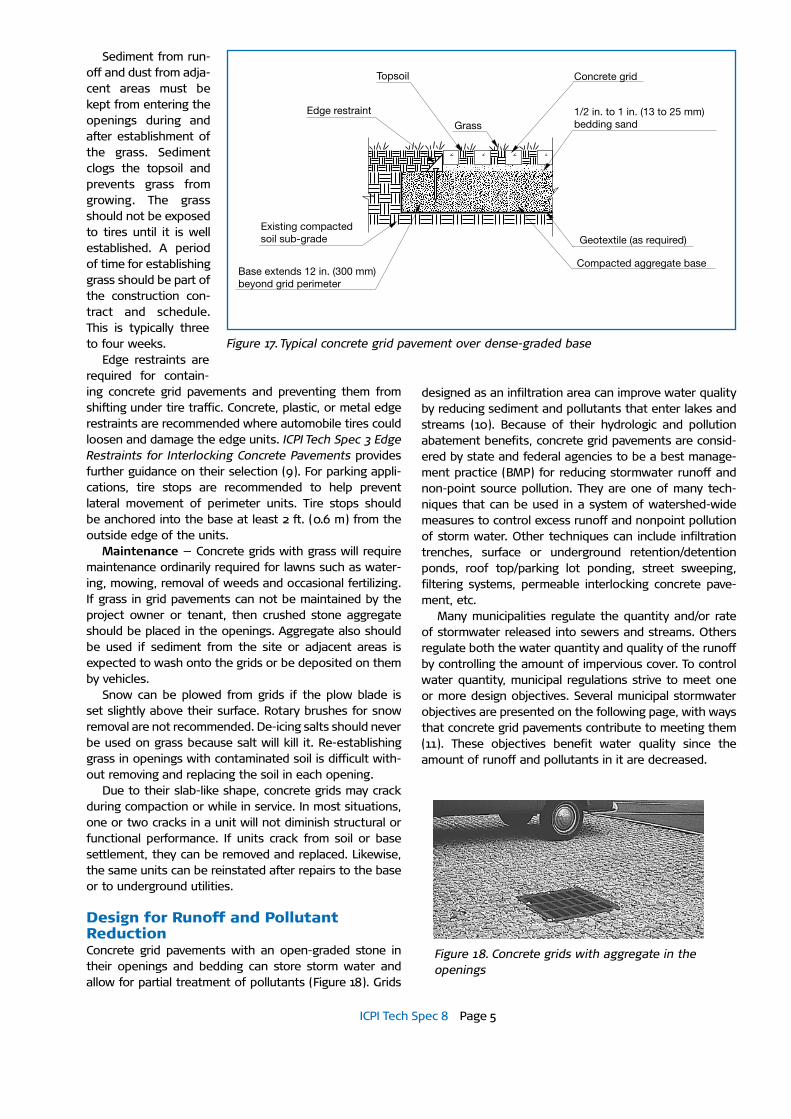
Construction of dense-graded bases — Prior to placing a dense-graded base, the soil subgrade should be uniformly compacted to at least 95% of standard Proctor density per ASTM D 698 (4). Dense-graded aggregate bases should be compacted to a minimum of 98% standard Proctor density (4). A well-compacted base is essential to shedding water and remaining stable in freeze-thaw conditions. Specifications for crushed stone aggregate base materials typically used under asphalt pavements are suitable under concrete grid pavements. If no local standards exist, gradation of the base mate-rial should conform to ASTM D 2940, Standard Specification for Graded Aggregate Material for Bases or Subbases for Highways or Airports (5). Figure 17 illustrates a typical cross-section with a dense-graded aggregate base.
For bases over poorly draining soils, perforated plas-tic, geotextile wrapped drain pipe is recommended for removing excess water. The pipe should be directed to a drainage swale, storm sewer, or stream. If draining soils is impractical, aggregate bases can be stabilized with 4 to 6 percent (by weight) of cement to increase strength during drainage or freeze-thaw.
The maximum surface tolerance of the compacted base should be ± 3/8 in. (±10 mm) over a 10 ft (3 m) straight-edge. The base should extend beyond the perimeter of the grids a minimum of 12 in. (300 mm) when there is no building or curb to restrain them. The extended perimeter increases the stability of the grids and facilitates installa-tion of staked edge restraints.
The gradation of the bedding sand should conform to ASTM C 33 (6) or CSA A23.1-FA1 (7). These gradations are given in the guide specification at the end of this bulletin. Limestone screenings, stone dust or masonry sand should not be used. The thickness of the bedding sand should be between 1/2 and 1 in. (13–25 mm), and screeded to a consistent thickness. If No. 8 stone is used for bedding and openings, this should be screeded to 1 in. (25 mm) thickness. This is typically accomplished with screed rails or bars placed on the compacted base. The bedding sand over the bars is pulled across them with a screed board to establish a consistent sand thickness. The sand should have a consistent moisture content but not be saturated. It should not be disturbed prior to placing the grids.
The grids are placed on the screeded bedding sand with the maximum joint spacing of 3/16 in. (5 mm). The units shouldn't be pushed or hammered such that they
touch each other. If the grids touch, they may crack, chip or spall under repeated traffic.
The units should be cut to fill any spaces along the edges prior to compaction. All installed units should be compacted into the bedding sand at the end of each day. Rainfall settles uncompacted sand, preventing the grids from pressing into the sand when compacted. If bedding sand is left uncompacted, it should be covered with plastic to protect it from rain. Otherwise, bedding sand saturated with rainfall prior to compaction will need to dry, be raked and re-screeded or be replaced. If left uncorrected, the grids will settle unevenly and move under traffic.
After the grids are placed, topsoil is spread across them and swept into the openings. Fertilizer may be mixed with the topsoil as well. Quantities should account for the concrete surface.
The grids are vibrated into the sand with a high-frequency (75-90 Hz), low-amplitude plate compactor. It should have a minimum centrifugal compaction force of 4,000 lbs (18 kN). Rollers or a mat should be attached to the plate of the compactor to protect the grids from cracking and chipping. The primary purpose of compaction is to create a level surface among the units. An occasional cracked unit from compaction will not compromise per-formance. Extensive cracking should be addressed on a job-by-job basis.
The openings should be seeded and completely filled with topsoil. Adding topsoil to the entire surface can assist in germination. Straw can be applied to protect the grass while it is growing. While labor-intensive, sod plugs can be inserted into the openings as an alternative to topsoil and seeding. Sod plugs require a reduced amount of topsoil in the openings so space is available for them.
The choice of grass variety is important to longev-ity under tires and drought. A limited amount of research on concrete grid pav-ers has shown that Merion Kentucky bluegrass, Kentucky 31 tall fescue, and Manhattan peren-nial ryegrass have a high tolerance to wear, a high poten-tial for recupera-tion from damage, and a low tendency toward thatch build-up (8). Turfgrass specialists may have further recommen-dations on species and seeding rates.
Lattice
Castellated
Figure 14. Types of Grid Pavement Units
Figure 15. Solid pavers used for bicycle parking and pedestrian access.
Figure 16. A parking lot with a dense-graded, crushed stone base.
ICPI Tech Spec 8 Page 5
Sediment from run-off and dust from adja-cent areas must be kept from entering the openings during and after establishment of the grass. Sediment clogs the topsoil and prevents grass from growing. The grass should not be exposed to tires until it is well established. A period of time for establishing grass should be part of the construction con-tract and schedule. This is typically three to four weeks.
Edge restraints are required for contain-ing concrete grid pavements and preventing them from shifting under tire traffic. Concrete, plastic, or metal edge restraints are recommended where automobile tires could loosen and damage the edge units. ICPI Tech Spec 3 Edge Restraints for Interlocking Concrete Pavements provides further guidance on their selection (9). For parking appli-cations, tire stops are recommended to help prevent lateral movement of perimeter units. Tire stops should be anchored into the base at least 2 ft. (0.6 m) from the outside edge of the units.
Maintenance — Concrete grids with grass will require maintenance ordinarily required for lawns such as water-ing, mowing, removal of weeds and occasional fertilizing. If grass in grid pavements can not be maintained by the project owner or tenant, then crushed stone aggregate should be placed in the openings. Aggregate also should be used if sediment from the site or adjacent areas is expected to wash onto the grids or be deposited on them by vehicles.
Snow can be plowed from grids if the plow blade is set slightly above their surface. Rotary brushes for snow removal are not recommended. De-icing salts should never be used on grass because salt will kill it. Re-establishing grass in openings with contaminated soil is difficult with-out removing and replacing the soil in each opening.
Due to their slab-like shape, concrete grids may crack during compaction or while in service. In most situations, one or two cracks in a unit will not diminish structural or functional performance. If units crack from soil or base settlement, they can be removed and replaced. Likewise, the same units can be reinstated after repairs to the base or to underground utilities.
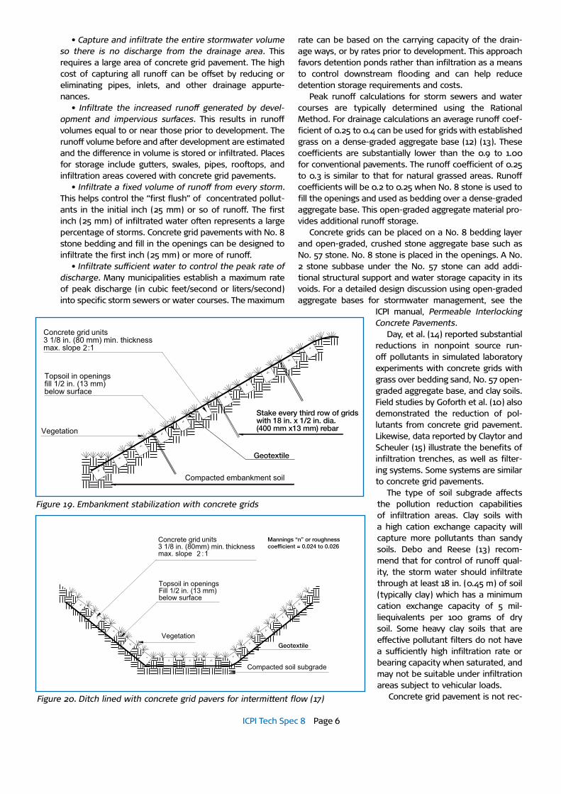
Design for Runoff and Pollutant ReductionConcrete grid pavements with an open-graded stone in their openings and bedding can store storm water and allow for partial treatment of pollutants (Figure 18). Grids
designed as an infiltration area can improve water quality by reducing sediment and pollutants that enter lakes and streams (10). Because of their hydrologic and pollution abatement benefits, concrete grid pavements are consid-ered by state and federal agencies to be a best manage-ment practice (BMP) for reducing stormwater runoff and non-point source pollution. They are one of many tech-niques that can be used in a system of watershed-wide measures to control excess runoff and nonpoint pollution of storm water. Other techniques can include infiltration trenches, surface or underground retention/detention ponds, roof top/parking lot ponding, street sweeping, filtering systems, permeable interlocking concrete pave-ment, etc.
Many municipalities regulate the quantity and/or rate of stormwater released into sewers and streams. Others regulate both the water quantity and quality of the runoff by controlling the amount of impervious cover. To control water quantity, municipal regulations strive to meet one or more design objectives. Several municipal stormwater objectives are presented on the following page, with ways that concrete grid pavements contribute to meeting them (11). These objectives benefit water quality since the amount of runoff and pollutants in it are decreased.
Base extends 12 in. (300 mm) beyond grid perimeter
Existing compactedsoil sub-grade
Edge restraint
Topsoil
Grass
Concrete grid
1/2 in. to 1 in. (13 to 25 mm)bedding sand
Geotextile (as required)
Compacted aggregate base
Figure 17. Typical concrete grid pavement over dense-graded base
Figure 18. Concrete grids with aggregate in the openings
ICPI Tech Spec 8 Page 6
• Capture and infiltrate the entire stormwater volume so there is no discharge from the drainage area. This requires a large area of concrete grid pavement. The high cost of capturing all runoff can be offset by reducing or eliminating pipes, inlets, and other drainage appurte-nances.
• Infiltrate the increased runoff generated by devel-opment and impervious surfaces. This results in runoff volumes equal to or near those prior to development. The runoff volume before and after development are estimated and the difference in volume is stored or infiltrated. Places for storage include gutters, swales, pipes, rooftops, and infiltration areas covered with concrete grid pavements.
• Infiltrate a fixed volume of runoff from every storm. This helps control the “first flush” of concentrated pollut-ants in the initial inch (25 mm) or so of runoff. The first inch (25 mm) of infiltrated water often represents a large percentage of storms. Concrete grid pavements with No. 8 stone bedding and fill in the openings can be designed to infiltrate the first inch (25 mm) or more of runoff.
• Infiltrate sufficient water to control the peak rate of discharge. Many municipalities establish a maximum rate of peak discharge (in cubic feet/second or liters/second) into specific storm sewers or water courses. The maximum
rate can be based on the carrying capacity of the drain-age ways, or by rates prior to development. This approach favors detention ponds rather than infiltration as a means to control downstream flooding and can help reduce detention storage requirements and costs.
Peak runoff calculations for storm sewers and water courses are typically determined using the Rational Method. For drainage calculations an average runoff coef-ficient of 0.25 to 0.4 can be used for grids with established grass on a dense-graded aggregate base (12) (13). These coefficients are substantially lower than the 0.9 to 1.00 for conventional pavements. The runoff coefficient of 0.25 to 0.3 is similar to that for natural grassed areas. Runoff coefficients will be 0.2 to 0.25 when No. 8 stone is used to fill the openings and used as bedding over a dense-graded aggregate base. This open-graded aggregate material pro-vides additional runoff storage.
Concrete grids can be placed on a No. 8 bedding layer and open-graded, crushed stone aggregate base such as No. 57 stone. No. 8 stone is placed in the openings. A No. 2 stone subbase under the No. 57 stone can add addi-tional structural support and water storage capacity in its voids. For a detailed design discussion using open-graded aggregate bases for stormwater management, see the
ICPI manual, Permeable Interlocking Concrete Pavements.
Day, et al. (14) reported substantial reductions in nonpoint source run-off pollutants in simulated laboratory experiments with concrete grids with grass over bedding sand, No. 57 open-graded aggregate base, and clay soils. Field studies by Goforth et al. (10) also demonstrated the reduction of pol-lutants from concrete grid pavement. Likewise, data reported by Claytor and Scheuler (15) illustrate the benefits of infiltration trenches, as well as filter-ing systems. Some systems are similar to concrete grid pavements.
The type of soil subgrade affects the pollution reduction capabilities of infiltration areas. Clay soils with a high cation exchange capacity will capture more pollutants than sandy soils. Debo and Reese (13) recom-mend that for control of runoff qual-ity, the storm water should infiltrate through at least 18 in. (0.45 m) of soil (typically clay) which has a minimum cation exchange capacity of 5 mil-liequivalents per 100 grams of dry soil. Some heavy clay soils that are effective pollutant filters do not have a sufficiently high infiltration rate or bearing capacity when saturated, and may not be suitable under infiltration areas subject to vehicular loads.
Concrete grid pavement is not rec-
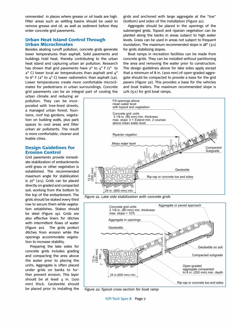
Stake every third row of gridswith 18 in. x 1/2 in. dia.(400 mm x13 mm) rebar
Geotextile
Mannings “n” or roughness coefficient = 0.024 to 0.026
Geotextile
Figure 19. Embankment stabilization with concrete grids
Figure 20. Ditch lined with concrete grid pavers for intermittent flow (17)
ICPI Tech Spec 8 Page 7
ommended in places where grease or oil loads are high. Filter areas such as settling basins should be used to remove grease and oil, as well as sediment before they enter concrete grid pavements.
Urban Heat Island Control Through Urban MicroclimatesBesides abating runoff pollution, concrete grids generate lower temperatures than asphalt. Solid pavements and buildings hold heat, thereby contributing to the urban heat island and capturing urban air pollution. Research has shown that grid pavements have 2° to 4° F (1° to 2° C) lower local air temperatures than asphalt and 4° to 6° F (2° to 4° C) lower radiometric than asphalt (12). Lower temperatures create more comfortable microcli-mates for pedestrians in urban surroundings. Concrete grid pavements can be an integral part of cooling the urban climate and reducing air pollution. They can be incor-porated with tree-lined streets, a managed urban forest, foun-tains, roof top gardens, vegeta-tion on building walls, plus park spaces to cool areas and filter urban air pollutants. The result is more comfortable, cleaner and livable cities.
Design Guidelines for Erosion ControlGrid pavements provide immedi-ate stabilization of embankments until grass or other vegetation is established. The recommended maximum angle for stabilization is 27° (2:1). Grids can be placed directly on graded and compacted soil, working from the bottom to the top of the embankment. The grids should be staked every third row to secure them while vegeta-tion establishes. Stakes should be steel (Figure 19). Grids are also effective liners for ditches with intermittent flows of water (Figure 20). The grids protect ditches from erosion while the openings accommodate vegeta-tion to increase stability.
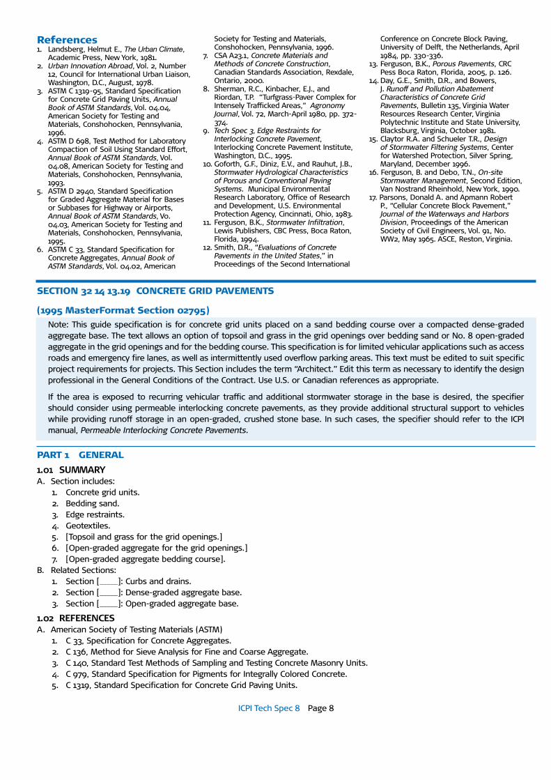
Preparing the lake sides for concrete grids includes grading and compacting the area above the water prior to placing the units. Aggregate is often placed under grids on banks to fur-ther prevent erosion. This layer should be at least 4 in. (100 mm) thick. Geotextile should be placed prior to installing the
grids and anchored with large aggregate at the “toe” (bottom) and sides of the installation (Figure 21).
Aggregate should be placed in the openings of the submerged grids. Topsoil and riparian vegetation can be planted along the banks in areas subject to high water levels. Grass can be used in areas not subject to frequent inundation. The maximum recommended slope is 18° (3:1) for grids stabilizing slopes.
Boat ramps in recreation facilities can be made from concrete grids. They can be installed without partitioning the area and removing the water prior to construction. The design guidelines above for lake sides apply except that a minimum of 8 in. (200 mm) of open-graded aggre-gate should be compacted to provide a base for the grid pavers (Figure 22). This provides a base for the vehicles and boat trailers. The maximum recommended slope is 12% (5:1) for grid boat ramps.
Figure 21. Lake side stabilization with concrete grids
Figure 22. Typical cross-section for boat ramp
ICPI Tech Spec 8 Page 8
References1. Landsberg, Helmut E., The Urban Climate,
Academic Press, New York, 1981. 2. Urban Innovation Abroad, Vol. 2, Number
12, Council for International Urban Liaison, Washington, D.C., August, 1978.
3. ASTM C 1319-95, Standard Specification for Concrete Grid Paving Units, Annual Book of ASTM Standards, Vol. 04.04, American Society for Testing and Materials, Conshohocken, Pennsylvania, 1996.
4. ASTM D 698, Test Method for Laboratory Compaction of Soil Using Standard Effort, Annual Book of ASTM Standards, Vol. 04.08, American Society for Testing and Materials, Conshohocken, Pennsylvania, 1993.
5. ASTM D 2940, Standard Specification for Graded Aggregate Material for Bases or Subbases for Highway or Airports, Annual Book of ASTM Standards, Vo. 04.03, American Society for Testing and Materials, Conshohocken, Pennsylvania, 1995.
6. ASTM C 33, Standard Specification for Concrete Aggregates, Annual Book of ASTM Standards, Vol. 04.02, American
Society for Testing and Materials, Conshohocken, Pennsylvania, 1996.
7. CSA A23.1, Concrete Materials and Methods of Concrete Construction, Canadian Standards Association, Rexdale, Ontario, 2000.
8. Sherman, R.C., Kinbacher, E.J., and Riordan, T.P. “Turfgrass-Paver Complex for Intensely Trafficked Areas,” Agronomy Journal, Vol. 72, March-April 1980, pp. 372-374.
9. Tech Spec 3, Edge Restraints for Interlocking Concrete Pavement, Interlocking Concrete Pavement Institute, Washington, D.C., 1995.
10. Goforth, G.F., Diniz, E.V., and Rauhut, J.B., Stormwater Hydrological Characteristics of Porous and Conventional Paving Systems. Municipal Environmental Research Laboratory, Office of Research and Development, U.S. Environmental Protection Agency, Cincinnati, Ohio, 1983.
11. Ferguson, B.K., Stormwater Infiltration, Lewis Publishers, CBC Press, Boca Raton, Florida, 1994.
12. Smith, D.R., “Evaluations of Concrete Pavements in the United States,” in Proceedings of the Second International
Conference on Concrete Block Paving, University of Delft, the Netherlands, April 1984, pp. 330-336.
13. Ferguson, B.K., Porous Pavements, CRC Pess Boca Raton, Florida, 2005, p. 126.
14. Day, G.E., Smith, D.R., and Bowers, J. Runoff and Pollution Abatement Characteristics of Concrete Grid Pavements, Bulletin 135, Virginia Water Resources Research Center, Virginia Polytechnic Institute and State University, Blacksburg, Virginia, October 1981.
15. Claytor R.A. and Schueler T.R., Design of Stormwater Filtering Systems, Center for Watershed Protection, Silver Spring, Maryland, December 1996.
16. Ferguson, B. and Debo, T.N., On-site Stormwater Management, Second Edition, Van Nostrand Rheinhold, New York, 1990.
17. Parsons, Donald A. and Apmann Robert P., “Cellular Concrete Block Pavement,” Journal of the Waterways and Harbors Division, Proceedings of the American Society of Civil Engineers, Vol. 91, No. WW2, May 1965. ASCE, Reston, Virginia.
SECTION 32 14 13.19 CONCRETE GRID PAVEMENTS
(1995 MasterFormat Section 02795)Note: This guide specification is for concrete grid units placed on a sand bedding course over a compacted dense-graded aggregate base. The text allows an option of topsoil and grass in the grid openings over bedding sand or No. 8 open-graded aggregate in the grid openings and for the bedding course. This specification is for limited vehicular applications such as access roads and emergency fire lanes, as well as intermittently used overflow parking areas. This text must be edited to suit specific project requirements for projects. This Section includes the term “Architect.” Edit this term as necessary to identify the design professional in the General Conditions of the Contract. Use U.S. or Canadian references as appropriate.
If the area is exposed to recurring vehicular traffic and additional stormwater storage in the base is desired, the specifier should consider using permeable interlocking concrete pavements, as they provide additional structural support to vehicles while providing runoff storage in an open-graded, crushed stone base. In such cases, the specifier should refer to the ICPI manual, Permeable Interlocking Concrete Pavements.
PART 1 GENERAL
1.01 SUMMARYA. Section includes:
1. Concrete grid units.2. Bedding sand.3. Edge restraints.4. Geotextiles.5. [Topsoil and grass for the grid openings.]6. [Open-graded aggregate for the grid openings.]7. [Open-graded aggregate bedding course].
B. Related Sections:1. Section [______]: Curbs and drains.2. Section [______]: Dense-graded aggregate base.3. Section [______]: Open-graded aggregate base.
1.02 REFERENCESA. American Society of Testing Materials (ASTM)
1. C 33, Specification for Concrete Aggregates.2. C 136, Method for Sieve Analysis for Fine and Coarse Aggregate.3. C 140, Standard Test Methods of Sampling and Testing Concrete Masonry Units.4. C 979, Standard Specification for Pigments for Integrally Colored Concrete.5. C 1319, Standard Specification for Concrete Grid Paving Units.

ICPI Tech Spec 8 Page 9
6. ASTM D 698, Standard Test Method for Laboratory Compaction Characteristics of Soil Using Standard Effort (12,000 ft-lbf/ft3 (600 kN-m/m3)).
7. D 2940, Standard Specification for Graded Aggregate Material for Bases or Subbases for Highways or Airports.8. D 5268, Specification for Topsoil Used for Landscaping Purposes.
B. Canadian Standards Association (CSA)1. CSA A23.1, Concrete Materials and Methods of Concrete Construction
C. Interlocking Concrete Pavement Institute (ICPI)1. Tech Spec technical bulletins.
1.03 SUBMITTALSA. In accordance with Conditions of the Contract and Division 1 Submittal Procedures Section.B. Manufacturer’s drawings and details: Indicate perimeter conditions, relationship to adjoining materials and assemblies,
expansion and control joints, paving slab [layout,] [patterns,] [color arrangement,] installation [and setting] details.C. Sieve analysis per ASTM C 136 for grading of bedding and base materials.
Note: Include D below if the grid openings will be filled with topsoil and grass seed, or sod plugs.
D. Source and content of topsoil and grass seed [sod].E. Concrete grid units:
1. Color selected by Architect.2. [Four] representative full-size samples of each grid type, thickness, color, finish that indicate the extremes of color
variation and texture expected in the finished installation. 3. Accepted samples become the standard of acceptance for the work.4. Test results from an independent testing laboratory for compliance of grid paving unit requirements to ASTM C 1319.5. Manufacturer’s certification of concrete grid units by ICPI as having met applicable ASTM standards.6. Manufacturer’s catalog literature, installation instructions, and material safety data sheets for the safe handling of the
specified materials and products.
1.04 QUALITY ASSURANCEA. Paving Subcontractor Qualifications:
1. Engage an experienced installer who has successfully completed grid pavement installations similar in design, material, and extent indicated for this Project.
2. Hold a current certificate from the Interlocking Concrete Pavement Institute Concrete Paver Installer Certification pro-gram.
B. Single-source Responsibility: Obtain each color, type, and variety of grids, joint materials and setting materials from single sources with resources to provide products and materials of consistent quality, appearance and physical properties without delaying progress of the Work.
C. Regulatory requirements and approvals: [Specify applicable licensing, bonding or other requirements of regulatory agen-cies.]
D. Mock-up1. Locate where directed by the Architect.2. Notify Architect in advance of dates when mock-ups will be erected.3. Install minimum [100] sf ([10] m2) of concrete grid units.4. Use this area to determine the quality of workmanship to be produced in the final unit of Work including surcharge of
the bedding sand layer, joint sizes, lines, pavement laying pattern(s), color(s), and texture.5. This area shall be used as the standard by which the work is judged.6. Subject to acceptance by the owner, mock up may be retained as part of the finished work. 7. If mock up is not retained, remove and properly dispose of.
1.05 DELIVERY, STORAGE, AND HANDLINGA. General: Comply with Division 1 Product Requirement SectionB. Deliver concrete grid units to the site in steel banded, plastic banded, or plastic wrapped packaging capable of transfer by
forklift or clamp lift. Unload grids at job site in such a manner that no damage occurs to the product or existing construc-tion.
C. Cover sand with waterproof covering to prevent exposure to rainfall or removal by wind. Secure the covering in place.D. Coordinate delivery and paving schedule to minimize interference with normal use of buildings adjacent to paving.
1.06 ENVIRONMENTAL CONDITIONSA. Do not install bedding materials or grid units during heavy rain or snowfall.B. Do not install bedding materials and grid units over frozen base materials.
ICPI Tech Spec 8 Page 10
C. Do not install frozen bedding materials.
1.07 GRID PAVER MAINTENANCE MATERIALS:A. Supply [ ] sf [( m2)] of [each type and color of grid unit] in unopened pallets with contents labeled. Store where directed.B. From the same production run as installed materials.
PART 2 PRODUCTS
2.01 CONCRETE GRID UNITSA. Manufacturer: [Specify ICPI member manufacturer name.].
1. Contact: [Specify ICPI member manufacturer contact information.].B. Concrete grid paver units, including the following:
1. Grid unit type: [Specify name of product group, castellated, lattice, etc.]a. [Material standard: Comply with material standards set forth in [ASTM C 1319.].b. Color [and finish]: [Specify color.] [Specify finish].c. Color Pigment Material Standard: Comply with ASTM C 979.d. Size: [Specify.] inches [([Specify.] mm)] x [ Specify.] inches [([Specify.] mm)] x [Specify.] inches [([Specify.] mm)] thick.
C. Manufactured in a plant where paving products are certified by ICPI as having passed ASTM requirements in this specification.
2.02 PRODUCT SUBSTITUTIONSA. Substitutions: No substitutions permitted.
2.03 BEDDING MATERIALS
Note: If openings are filled with topsoil, use sand bedding. If the openings are filled with open-graded aggregate for additional runoff storage, the same aggregate should be used for the bedding. Edit 2.03 and 2.04 accordingly.
A. General – Sieved per ASTM C 136.B. Bedding Sand
Note: The type of sand used for bedding is often called concrete sand. Sands vary regionally. Contact contractors local to the project and confirm sand(s) successfully used in previous similar applications. Bedding sand is not used in ditch liner applica-tions, slope protection, riparian stabilization or with boat ramps constructed with concrete grid units.
1. Washed, clean, hard, durable crushed gravel or stone, free from shale, clay, friable materials, organic matter, frozen lumps, and other deleterious substances.
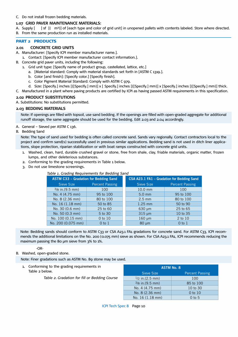
2. Conforming to the grading requirements in Table 1 below. 3. Do not use limestone screenings.
-OR-B. Washed, open-graded stone.
Note: Finer gradations such as ASTM No. 89 stone may be used.
1. Conforming to the grading requirements in Table 2 below.
Table 1. Grading Requirements for Bedding Sand
ASTm C33 – Gradation for bedding Sand
Sieve Size Percent Passing 3/8 in.(9.5 mm) 100
No. 4 (4.75 mm) 95 to 100 No. 8 (2.36 mm) 80 to 100
No. 16 (1.18 mm) 50 to 85 No. 30 (0.6 mm) 25 to 60 No. 50 (0.3 mm) 5 to 30
No. 100 (0.15 mm) 0 to 10 No. 200 (0.075 mm) 0 to 1
CSA A23.1 FA1 – Gradation for bedding Sand
Sieve Size Percent Passing 10.0 mm 1005.0 mm 95 to 100 2.5 mm 80 to 100
1.25 mm 50 to 90 630 µm 25 to 65 315 µm 10 to 35 160 µm 2 to 10 80 µm 0 to 1
Note: Bedding sands should conform to ASTM C33 or CSA A23.1 FA1 gradations for concrete sand. For ASTM C33, ICPI recom-mends the additional limitations on the No. 200 (0.075 mm) sieve as shown. For CSA A23.1 FA1, ICPI recommends reducing the maximum passing the 80 μm sieve from 3% to 1%.
ASTm No. 8
Sieve Size Percent Passing 1/2 in.(2.5 mm) 1003/8 in.(9.5 mm) 85 to 100
No. 4 (4.75 mm) 10 to 30 No. 8 (2.36 mm) 0 to 10
No. 16 (1.18 mm) 0 to 5
Table 2. Gradation for fill or Bedding Course
ICPI Tech Spec 8 Page 11
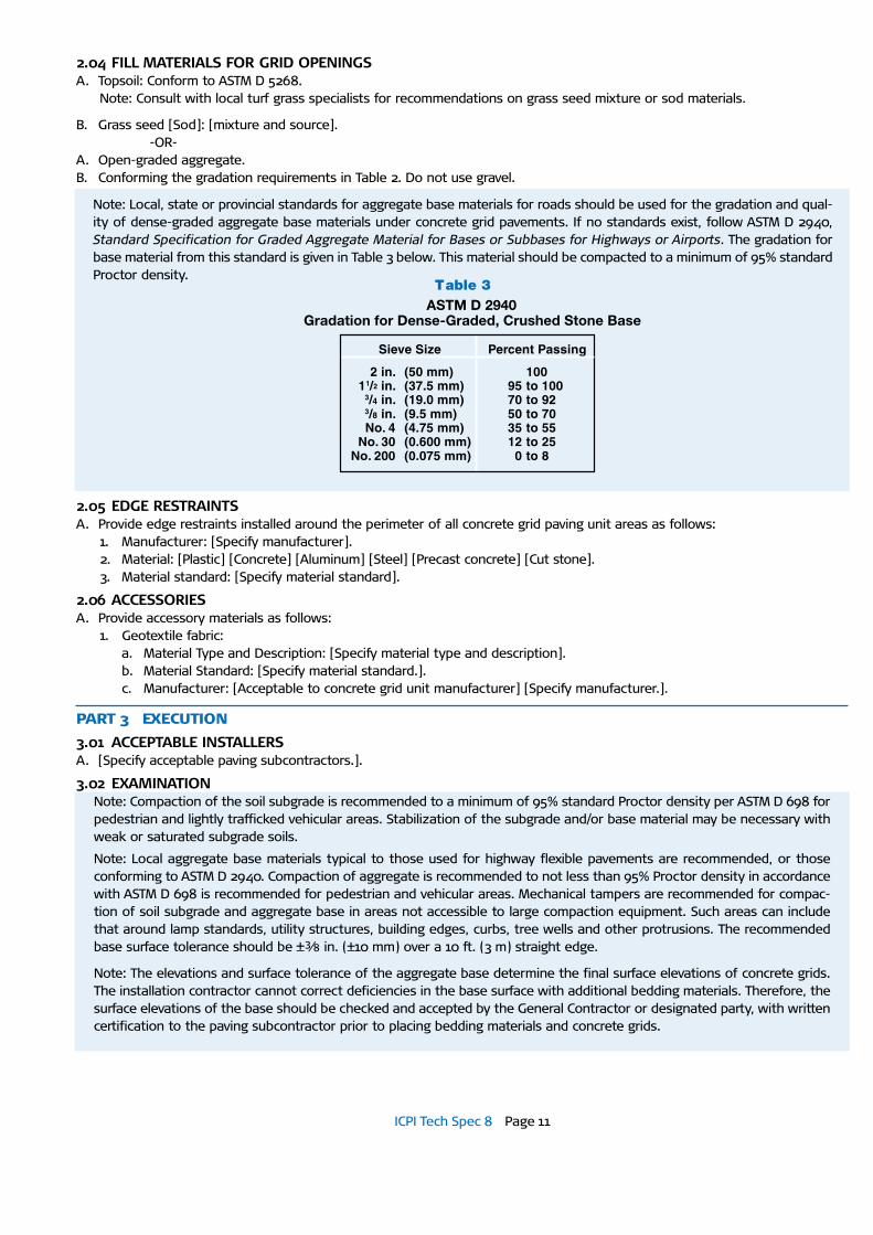
Table 3ASTM D 2940
Gradation for Dense-Graded, Crushed Stone Base
Sieve Size Percent Passing
2 in. (50 mm) 10011/2 in. (37.5 mm) 95 to 100
3/4 in. (19.0 mm) 70 to 923/8 in. (9.5 mm) 50 to 70No. 4 (4.75 mm) 35 to 55
No. 30 (0.600 mm) 12 to 25No. 200 (0.075 mm) 0 to 8
Note: Local, state or provincial standards for aggregate base materials for roads should be used for the gradation and qual-ity of dense-graded aggregate base materials under concrete grid pavements. If no standards exist, follow ASTM D 2940, Standard Specification for Graded Aggregate Material for Bases or Subbases for Highways or Airports. The gradation for base material from this standard is given in Table 3 below. This material should be compacted to a minimum of 95% standard Proctor density.
2.04 FILL MATERIALS FOR GRID OPENINGSA. Topsoil: Conform to ASTM D 5268.
Note: Consult with local turf grass specialists for recommendations on grass seed mixture or sod materials.
B. Grass seed [Sod]: [mixture and source]. -OR-A. Open-graded aggregate.B. Conforming the gradation requirements in Table 2. Do not use gravel.
2.05 EDGE RESTRAINTSA. Provide edge restraints installed around the perimeter of all concrete grid paving unit areas as follows:
1. Manufacturer: [Specify manufacturer].2. Material: [Plastic] [Concrete] [Aluminum] [Steel] [Precast concrete] [Cut stone].3. Material standard: [Specify material standard].
2.06 ACCESSORIESA. Provide accessory materials as follows:
1. Geotextile fabric: a. Material Type and Description: [Specify material type and description].b. Material Standard: [Specify material standard.].c. Manufacturer: [Acceptable to concrete grid unit manufacturer] [Specify manufacturer.].
PART 3 EXECUTION
3.01 ACCEPTABLE INSTALLERSA. [Specify acceptable paving subcontractors.].
3.02 EXAMINATIONNote: Compaction of the soil subgrade is recommended to a minimum of 95% standard Proctor density per ASTM D 698 for pedestrian and lightly trafficked vehicular areas. Stabilization of the subgrade and/or base material may be necessary with weak or saturated subgrade soils.
Note: Local aggregate base materials typical to those used for highway flexible pavements are recommended, or those conforming to ASTM D 2940. Compaction of aggregate is recommended to not less than 95% Proctor density in accordance with ASTM D 698 is recommended for pedestrian and vehicular areas. Mechanical tampers are recommended for compac-tion of soil subgrade and aggregate base in areas not accessible to large compaction equipment. Such areas can include that around lamp standards, utility structures, building edges, curbs, tree wells and other protrusions. The recommended base surface tolerance should be ±3 ⁄8 in. (±10 mm) over a 10 ft. (3 m) straight edge.
Note: The elevations and surface tolerance of the aggregate base determine the final surface elevations of concrete grids. The installation contractor cannot correct deficiencies in the base surface with additional bedding materials. Therefore, the surface elevations of the base should be checked and accepted by the General Contractor or designated party, with written certification to the paving subcontractor prior to placing bedding materials and concrete grids.

ICPI Tech Spec 8 Page 12
A. Acceptance of site verification conditions:1. Contractor shall inspect, accept and verify in writing to the grid installation subcontractor that site conditions meet
specifications for the following items prior to installation of bedding materials and concrete grid units:a. Verify that drainage and subgrade preparation, compacted density and elevations conform to specified requirements. b. Verify that geotextiles, if applicable, have been placed according to drawing and specifications. c. Verify that base materials, thickness, [compacted density,] surface tolerances and elevations conform to specified
requirements.d. Provide written density test results for the soil subgrade, base materials to the Owner, Contractor, and grid installa-
tion subcontractor.2. Do not proceed with installation of bedding materials and concrete grids until [subgrade soil and] base conditions are
corrected by the Contractor or designated subcontractor.
3.03 PREPARATIONA. Verify that base is dry, certified by Contractor as meeting material, installation and grade specifications [and geotextile] are
ready to support sand, [edge restraints,] grids and imposed loads.B. Edge Restraint Preparation:
1. Install edge restraints per the drawings [and manufacturer’s recommendations] [at the indicated elevations.].2. Mount directly to finished base. Do not install on bedding sand.3. The minimum distance from the outside edge of the base to the spikes shall be equal to the thickness of the base.
3.04 INSTALLATIONA. Spread the sand [No. 8 stone] evenly over the compacted, dense-graded base course and screed uniformly to ½ to 1 in.
(13 to 25 mm). Place sufficient sand [stone] to stay ahead of the laid grids. B. Ensure the grid units are free from foreign materials before installation.C. Lay the grid units on the bedding sand in the pattern(s) shown on the drawings. Maintain straight joint lines.D. Joints between the grids shall not exceed [3 ⁄ 16 in. (5 mm)].E. Fill gaps at the edges of the paved area with cut grid pavers or edge units.F. Cut grid pavers to be placed along the edge with a double-bladed splitter or masonry saw.G. Sweep [top soil][No. 8 aggregate] into the joints and openings until full. H. Sweep the grid surface clear prior to compacting.I. Compact and seat the grids into the screeded [bedding sand] [No. 8 aggregate] using a low-amplitude, 75-90 Hz plate com-
pactor capable of at least 4,000 lbs. (18 kN) centrifugal compaction force. Use rollers or a rubber or neoprene pad between the compactor and grids to prevent cracking or chipping. Do not compact within 6 ft (2 m) of the unrestrained edges of the grid units.
J. All work to within 6 ft (2 m) of the laying face must be left fully compacted at the completion of each day.K. [Broadcast grass seed at the rate recommended by seed source.][Place sod plugs into openings.] [Add topsoil to the surface
to cover the seeds.]L. Remove excess [topsoil][No. 8 aggregate] on surface when the job is complete.M. [Distribute straw covering to protect germinating grass seed [sod]. Water entire area. Do not traffic pavement for [30] days.]
if seeded.
3.05 FIELD QUALITY CONTROLA. After removal of excess top soil/aggregate, check final elevations for conformance to the drawings. Allow 1 ⁄8 to 1 ⁄4 in. (3 to 6
mm) above specified surface elevations to compensate for minor settlement. B. The final surface tolerance from grade elevations shall not deviate more than ± 3 ⁄8 in. (10 mm) over a 10 ft (3 m) straight-
edge. C. The surface elevation of grid units shall be 1 ⁄8 to 1 ⁄4 in. (3 to 6 mm) above adjacent drainage inlets, concrete collars or chan-
nels.D. Lippage: No greater than 1 ⁄8 in. (3 mm) difference in height between adjacent grid units.
3.06 PROTECTIONA. After work in the section is complete, the Contractor shall be responsible for protecting work from damage due to subse-
quent construction activity on the site. END OF SECTION
WARNING: The content of ICPI Tech Spec technical bulletins is intend-ed for use only as a guideline. It is NOT intended for use or reliance upon as an industry standard, certification or as a specification. ICPI makes no promises, representations or warranties of any kind, expressed or implied, as to the content of the Tech Spec Technical Bulletins and disclaims any liability for damages resulting from the use of Tech Spec Technical Bulletins. Professional assistance should be sought with respect to the design, specifications and construc-tion of each project.
Interlocking Concrete Pavement Institute
13921 Park Center Road, Suite 270
Herndon, VA 20171
In Canada:
P.O. Box 1150
Uxbridge, ON L9P 1N4
Canada
Tel: (703) 657-6900
Fax: (703) 657-6901
E-mail: [email protected]
Web: www.icpi.org