Tech 2 Report - Penn State Engineering 2... · report, calculations, design ... were the Wheeling...
32
Chris Shelow Structural Advisor: M. Kevin Parfitt Koshland Integrated Natural Science Center 10/31/05 AE 481W Structural Technical Report 2 Pro-Con Structural Study of Alternate Floor Systems Executive Summary The purpose of this report is to provide a descriptive analysis of, as well as a comparison between, the existing floor system of the Koshland Integrated Natural Science Center and the design of four alternate typical floor systems. The report provides detailed information on the current floor system and also the factored loads that were used to design the existing system. The design loads were taken from the drawings and confirmed with the BOCA 1993 code. The analysis focused on a typical bay of the current floor system which was calculated by hand and was also verified with the PCI Manual for the Design of Hollow Core Slabs (2 nd Edition) and the CRSI Handbook (2002). The alternative floor designs were also analyzed by hand calculations which can be reviewed in the Appendices following this report. The following portion of this report consists of the designing of four floor systems as alternatives to the existing system. All four systems are significantly different from one another. The floor systems that were selected for design include a one-way pan joist system, an open-web steel joist system, a composite beam/composite slab system, and a precast double tee beam system. In this section of the report, each alternative floor system is described, followed by a sketch of the typical bay incorporating the system described. In addition, several advantages and disadvantages of each of the alternative systems are discussed and compared briefly. Also, as referenced in the body of the report, calculations, design tables, and complete design details are included in the report as Appendices. Finally, the last section of the report compares the advantages and disadvantages of each system in table format. The categories that are compared as the advantages and disadvantages are floor depth, self weight of the system, impact of construction schedule, and cost. With the information from the comparison table, the conclusion of the report emphasizes that the existing system proved to be the most efficient overall for this building. However there are other systems that could be considered as realistic possible alternatives such as the open web steel joist system or the double tee beam system.
-
Upload
vuongkhanh -
Category
Documents
-
view
215 -
download
0
Transcript of Tech 2 Report - Penn State Engineering 2... · report, calculations, design ... were the Wheeling...

Chris Shelow Structural
Advisor: M. Kevin Parfitt Koshland Integrated Natural Science Center
10/31/05 AE 481W
Structural Technical Report 2 Pro-Con Structural Study of Alternate Floor Systems
Executive Summary The purpose of this report is to provide a descriptive analysis of, as well as a comparison between, the existing floor system of the Koshland Integrated Natural Science Center and the design of four alternate typical floor systems. The report provides detailed information on the current floor system and also the factored loads that were used to design the existing system. The design loads were taken from the drawings and confirmed with the BOCA 1993 code. The analysis focused on a typical bay of the current floor system which was calculated by hand and was also verified with the PCI Manual for the Design of Hollow Core Slabs (2nd Edition) and the CRSI Handbook (2002). The alternative floor designs were also analyzed by hand calculations which can be reviewed in the Appendices following this report. The following portion of this report consists of the designing of four floor systems as alternatives to the existing system. All four systems are significantly different from one another. The floor systems that were selected for design include a one-way pan joist system, an open-web steel joist system, a composite beam/composite slab system, and a precast double tee beam system. In this section of the report, each alternative floor system is described, followed by a sketch of the typical bay incorporating the system described. In addition, several advantages and disadvantages of each of the alternative systems are discussed and compared briefly. Also, as referenced in the body of the report, calculations, design tables, and complete design details are included in the report as Appendices. Finally, the last section of the report compares the advantages and disadvantages of each system in table format. The categories that are compared as the advantages and disadvantages are floor depth, self weight of the system, impact of construction schedule, and cost. With the information from the comparison table, the conclusion of the report emphasizes that the existing system proved to be the most efficient overall for this building. However there are other systems that could be considered as realistic possible alternatives such as the open web steel joist system or the double tee beam system.

Existing Floor System Design The Koshland Integrated Natural Science Center combines four stories of laboratory and class room spaces with additional office space, library, and mechanical rooms. Laboratory spaces are located on each of the four floors. In addition, mechanical rooms are located on the ground floor and the fourth floor, classrooms are found on the first floor, offices are found on the second floor, and the third floor is the location for the library. The library area has a second mezzanine level which is on the fourth floor. The floor framing is typical throughout the East and West wings of the building, with the exception of the second level library found on the fourth floor of the West Wing. The similarities include member sizes, locations, and spans. Below is a diagram of the typical floor layout for the entire building.
The existing floor design of a typical lab floor layout is comprised of precast concrete hollow core planks that are supported by precast beams. For this analysis, a typical framing bay from the East Wing spanning from column lines 16 to 17 and U to W has been selected. The typical span for the hollow core planks is 31’-5”. The beams typically span 21’-0”. Currently, the design calls for hollow core planks that are 10” deep with a 2” topping slab. It is assumed that the planks have a length of 4’ in the short span direction. Also, since the reinforcement is not called out on the drawings, it is assumed to be (6) – 0.6” diameter prestressed tendons. The precast beams that support the floor system are dimensioned at 20”x12”. The reinforcement of the beams is unknown, therefore, it is assumed to be two layers of (7) – 0.6” diameter prestressed strands at the bottom and (6) - #11 bars in compression at the top. The precast concrete is also assumed to have a compressive strength of 5 ksi.
Typical bay selected for design

Floor Loads The loads used in the analysis of the existing floor system were taken as typical floor loads for the chosen bay. These floor loads used for this typical bay may not be representative of the entire structure due to specified increased loading requirements for other locations throughout the building. The following is a breakdown of the dead and live loads that were used for the typical bay. Live Loads (psf):
Typical floors 100
Dead Loads (psf): Ceiling 5 Mech., elec., & plumb. 10 Framing 15 10” hollow core planks w/2” topping 91 Partitions 30
Hollow Core Floor System Design Dead Loads (psf) Live Loads (psf) Ceiling 5 Typical floor 100 MEP 10 Framing 15 Hollow core planks w/topping 91 Partitions 30 Total: 151 Total: 100 Span (ft.) Tributary Width (ft.) Tributary Area (sq. ft.) TLL (psf) TDL (psf) wu (psf) wu (klf) Mmax (ft. kips)
31.42 4 125.68 100 151 341.2 1.36 142.9
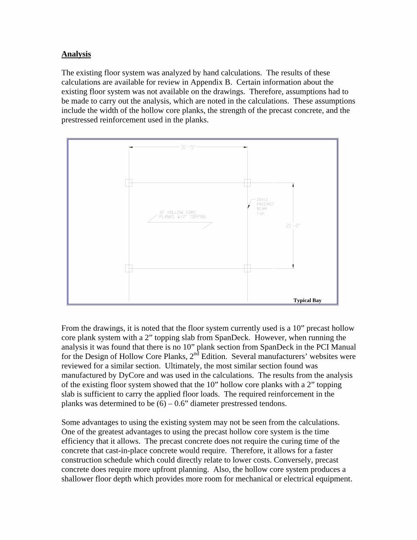
Analysis The existing floor system was analyzed by hand calculations. The results of these calculations are available for review in Appendix B. Certain information about the existing floor system was not available on the drawings. Therefore, assumptions had to be made to carry out the analysis, which are noted in the calculations. These assumptions include the width of the hollow core planks, the strength of the precast concrete, and the prestressed reinforcement used in the planks.
From the drawings, it is noted that the floor system currently used is a 10” precast hollow core plank system with a 2” topping slab from SpanDeck. However, when running the analysis it was found that there is no 10” plank section from SpanDeck in the PCI Manual for the Design of Hollow Core Planks, 2nd Edition. Several manufacturers’ websites were reviewed for a similar section. Ultimately, the most similar section found was manufactured by DyCore and was used in the calculations. The results from the analysis of the existing floor system showed that the 10” hollow core planks with a 2” topping slab is sufficient to carry the applied floor loads. The required reinforcement in the planks was determined to be (6) – 0.6” diameter prestressed tendons. Some advantages to using the existing system may not be seen from the calculations. One of the greatest advantages to using the precast hollow core system is the time efficiency that it allows. The precast concrete does not require the curing time of the concrete that cast-in-place concrete would require. Therefore, it allows for a faster construction schedule which could directly relate to lower costs. Conversely, precast concrete does require more upfront planning. Also, the hollow core system produces a shallower floor depth which provides more room for mechanical or electrical equipment.
Typical Bay
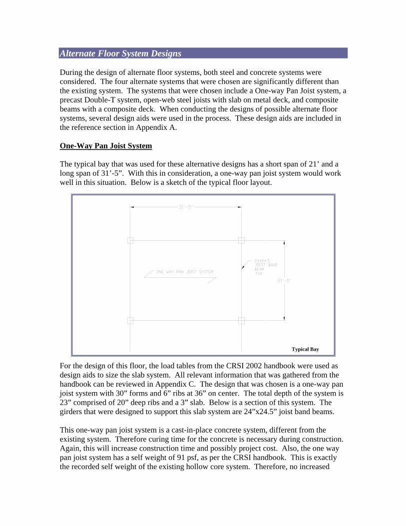
Alternate Floor System Designs During the design of alternate floor systems, both steel and concrete systems were considered. The four alternate systems that were chosen are significantly different than the existing system. The systems that were chosen include a One-way Pan Joist system, a precast Double-T system, open-web steel joists with slab on metal deck, and composite beams with a composite deck. When conducting the designs of possible alternate floor systems, several design aids were used in the process. These design aids are included in the reference section in Appendix A. One-Way Pan Joist System The typical bay that was used for these alternative designs has a short span of 21’ and a long span of 31’-5”. With this in consideration, a one-way pan joist system would work well in this situation. Below is a sketch of the typical floor layout.
For the design of this floor, the load tables from the CRSI 2002 handbook were used as design aids to size the slab system. All relevant information that was gathered from the handbook can be reviewed in Appendix C. The design that was chosen is a one-way pan joist system with 30” forms and 6” ribs at 36” on center. The total depth of the system is 23” comprised of 20” deep ribs and a 3” slab. Below is a section of this system. The girders that were designed to support this slab system are 24”x24.5” joist band beams. This one-way pan joist system is a cast-in-place concrete system, different from the existing system. Therefore curing time for the concrete is necessary during construction. Again, this will increase construction time and possibly project cost. Also, the one way pan joist system has a self weight of 91 psf, as per the CRSI handbook. This is exactly the recorded self weight of the existing hollow core system. Therefore, no increased
Typical Bay

loading due to self weight will occur. However, as previously stated, this system has a total depth of 23” which is much larger than the existing system. This is one disadvantage of incorporating the one way pan joist system. The increase in depth will take away from ceiling space for mechanical and electrical systems. Open Web Steel Joist System When designing the second alternative floor system, an open web steel joist system, the Wheeling Deck Product Catalog was used as a design aid. The design produced a non-composite 3” concrete slab on a 9/16” Tensilform metal deck. The second design aid used with this open web steel joist system was the New Columbia Joist Company (NCJ) Joist Catalog. From the design tables in the catalog, a 20LH07 open web steel joist was selected for the design. The depth of the joist is 20”. Three rows of 2x2x1/8 steel angles for bridging are required in the design of the open web joists. The third design aid used for this floor system was the LRFD Manual of Steel Construction (Third Edition) and it was used to design the steel girders to support the open web joists. From the design tables, the girder was sized to be a W24x76. All design details from design aids and calculations are available for review in Appendix D.
The depth of the open web steel joist system was designed to be 20”. This produces a greater ceiling depth. However, space for mechanical and electric systems may not be compromised. Since the joists are constructed with open webs, the voids in the webs will provide adequate room for MEP systems. In addition, the total weight of the slab on deck and joists is 51 psf. This is significantly less than the 91 psf self weight of the existing floor system. This reduction in self weight could result in smaller framing members. However, this system does require a spacing of 3’-6” for the open web steel joists. For a typical span, this produces seven joists per span. With this in consideration, and the use
Typical Bay

of steel W24x76 girders, the cost of materials is considerably higher than the existing precast hollow core system. Composite Beam/Composite Slab The third alternative floor system that was considered is a composite beam with a composite slab on deck system. Design aids that were used for this floor system design were the Wheeling Deck Products Catalog and the LRFD Manual for Steel Construction (Third Edition). The design for the composite slab resulted in a 4” slab on a 1-1/2” metal deck. The composite beam was designed to be a W16x26 steel beam. From the calculations, a total of 26 shear studs are required for full composite action for the beams. When designing for the steel girders, the results yielded a W18x40 steel girder with 40 shear studs to ensure full composite action. Below is a typical floor layout for this floor system. For full design details and calculations, see Appendix E.
The total depth of the composite beam/composite slab system is 30”. When compared to a depth of 12” from the existing precast hollow core system, this alternative system will certainly decrease ceiling space. This is considered a disadvantage for the location of the MEP systems as well. Also, the self weight of this floor system is substantially larger than that of the existing system. This could cause increased loading on the framing members in flexure, as well as raise the cost of materials for the floor system. However, this system presents a spacing of 7’ for the steel beams which results in fewer members. This could actually decrease the cost of the materials for the floor system.
Typical Bay

Precast Double Tee Beam System The final consideration for an alternative floor system was a double tee beam system. The design aid used for this floor system was the PCI Manual. Using the applied floor loads, the design resulted in an 8LDT24 + 2 system. This particular section is an 8’ wide double tee beam that is 24” in depth. A two inch topping is applied on top of the double tee beams. The double tee beams are reinforced with (6)-1/2” prestressed strands that run straight through the section. For a girder to support this floor system, a 28IT24 inverted tee beam was selected in the design. This girder has beam seat depth of 12” and an overall depth of 24”. It is reinforced with (11)-1/2” diameter low-lax prestressed strands. For full design details and calculations, see Appendix F.
The overall depth of the double tee beam floor system is 24”. This is considerably larger than that of 12” from the existing system. With this increase in depth, the ceiling space will be reduced forcing a larger plenum space for MEP systems. However, this system is still advantageous. Since this floor system is precast concrete, the concrete will not need to cure once it is installed. This will cut down on time in the construction schedule and reduce cost. In addition, the double tee beam system has a self weight of 40 psf, which is lighter than the 91 psf self weight of the existing system. This results in lighter loading on framing members which could reduce the size of the framing members, which, in return, saves cost of materials.
Typical Bay

Floor System Design Comparisons
System Description Total Depth (in) Self Weight (psf) Impact on Schedule Cost (R.S. Means Values,
$/sq.ft.)
1-5 (1=worst, 5=best) Mat'l. Labor Total
Existing Hollow Core Planks 12 91 5 6.10 2.32 8.42 Alternate #1 One Way Pan Joist 23 91 2 4.62 8.15 12.77 Alternate #2 Open Web Steel Joist 20 51 1 8.50 4.63 13.13 Alternate #3 Comp. Beam/Comp. Slab 20 40 3 9.30 5.40 14.70
Alternate #4 Double Tee Beam 24 62.5 4 4.96 1.70 6.83
Conclusion The results from the comparisons of the existing and alternate floor systems conclude that the existing floor system is the most efficient in physical properties, construction time, and cost. However, some of the alternate systems may be seen as realistic solutions to an alternative floor design. For instance, open web steel joist system offers a lighter solution for the floor system, although it sacrifices some ceiling space. Also, the double tee beam offers a design that is lighter than the existing hollow core system and is almost as time efficient as the existing system. In addition, the double tee beam system is the most cost effective system that was analyzed. However, the overall depth of the double tee beam system is twice that of the existing hollow core system. The above table compares all floor systems that were analyzed in a number of different categories.

Appendix A
References
PCI Design Handbook, Precast and Prestressed Concrete, 5th Edition PCI Manual for the Design of Hollow Core Slabs, 2nd Edition CRSI Handbook, 2002 Wheeling Deck Product Catalog New Columbia Joist Catalog LRFD Manual for Steel Construction, 3rd Edition R.S. Means 2005, Assemblies Cost Estimates
Appendix B
Existing Floor System Design Precast Hollow Core Planks


Appendix C
Alternate Floor System #1 One Way Pan Joist System


One Way Pan Joist (CRSI 2002)

Joist Band Beam – Girder (CRSI 2002)

Appendix D
Alternate Floor System #2 Open Web Steel Joist System


Non-Composite Metal Deck (Wheeling Deck Products)

Open Web Steel Joist (NCJ Joist Catalog)
Appendix E
Alternate Floor System #3 Composite Beam/Composite Slab


Composite Metal Deck (Wheeling Deck Products)

Appendix F
Alternate Floor System #4 Double Tee Beam System

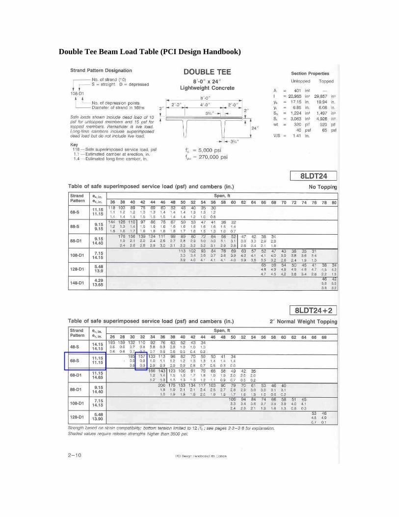
Double Tee Beam Load Table (PCI Design Handbook)

Inverted Tee Beam – Girder Design (PCI Design Handbook)

![ABC-UTC Guide for: Full-Depth Precast Concrete (FDPC) Deck ......The LRFD Guide Specification for Accelerated Bridge Construction specifies that [5]FDPC deck panels themselves should](https://static.fdocuments.in/doc/165x107/5e98e8bef7eb272b8624f396/abc-utc-guide-for-full-depth-precast-concrete-fdpc-deck-the-lrfd-guide.jpg)