TecCrete Access Flooring - McGowan Office Interiors Resources... · 42 Bathroom ... TecCrete Access...
100
Application Guide TecCrete Access Flooring TecCrete ®
Transcript of TecCrete Access Flooring - McGowan Office Interiors Resources... · 42 Bathroom ... TecCrete Access...

Application Guide
TecCrete Access Flooring
TecCrete®
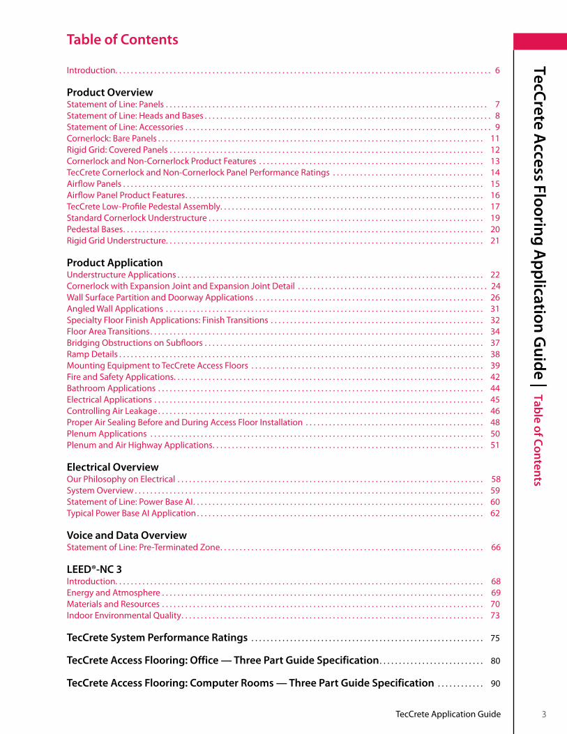
TecCrete Application Guide 3
TecCrete Access Flooring A
pplication Guide | Table of Contents
Introduction . . . . . . . . . . . . . . . . . . . . . . . . . . . . . . . . . . . . . . . . . . . . . . . . . . . . . . . . . . . . . . . . . . . . . . . . . . . . . . . . . . . . . . . . . . . . . . . . . 6
Product OverviewStatement of Line: Panels . . . . . . . . . . . . . . . . . . . . . . . . . . . . . . . . . . . . . . . . . . . . . . . . . . . . . . . . . . . . . . . . . . . . . . . . . . . . . . . . . . . 7Statement of Line: Heads and Bases . . . . . . . . . . . . . . . . . . . . . . . . . . . . . . . . . . . . . . . . . . . . . . . . . . . . . . . . . . . . . . . . . . . . . . . . . . 8Statement of Line: Accessories . . . . . . . . . . . . . . . . . . . . . . . . . . . . . . . . . . . . . . . . . . . . . . . . . . . . . . . . . . . . . . . . . . . . . . . . . . . . . . . 9Cornerlock: Bare Panels . . . . . . . . . . . . . . . . . . . . . . . . . . . . . . . . . . . . . . . . . . . . . . . . . . . . . . . . . . . . . . . . . . . . . . . . . . . . . . . . . . . . 11Rigid Grid: Covered Panels . . . . . . . . . . . . . . . . . . . . . . . . . . . . . . . . . . . . . . . . . . . . . . . . . . . . . . . . . . . . . . . . . . . . . . . . . . . . . . . . . 12Cornerlock and Non-Cornerlock Product Features . . . . . . . . . . . . . . . . . . . . . . . . . . . . . . . . . . . . . . . . . . . . . . . . . . . . . . . . . . 13TecCrete Cornerlock and Non-Cornerlock Panel Performance Ratings . . . . . . . . . . . . . . . . . . . . . . . . . . . . . . . . . . . . . . . 14Airflow Panels . . . . . . . . . . . . . . . . . . . . . . . . . . . . . . . . . . . . . . . . . . . . . . . . . . . . . . . . . . . . . . . . . . . . . . . . . . . . . . . . . . . . . . . . . . . . . 15Airflow Panel Product Features . . . . . . . . . . . . . . . . . . . . . . . . . . . . . . . . . . . . . . . . . . . . . . . . . . . . . . . . . . . . . . . . . . . . . . . . . . . . . 16TecCrete Low-Profile Pedestal Assembly . . . . . . . . . . . . . . . . . . . . . . . . . . . . . . . . . . . . . . . . . . . . . . . . . . . . . . . . . . . . . . . . . . . . 17Standard Cornerlock Understructure . . . . . . . . . . . . . . . . . . . . . . . . . . . . . . . . . . . . . . . . . . . . . . . . . . . . . . . . . . . . . . . . . . . . . . . 19Pedestal Bases . . . . . . . . . . . . . . . . . . . . . . . . . . . . . . . . . . . . . . . . . . . . . . . . . . . . . . . . . . . . . . . . . . . . . . . . . . . . . . . . . . . . . . . . . . . . . 20Rigid Grid Understructure . . . . . . . . . . . . . . . . . . . . . . . . . . . . . . . . . . . . . . . . . . . . . . . . . . . . . . . . . . . . . . . . . . . . . . . . . . . . . . . . . . 21
Product ApplicationUnderstructure Applications . . . . . . . . . . . . . . . . . . . . . . . . . . . . . . . . . . . . . . . . . . . . . . . . . . . . . . . . . . . . . . . . . . . . . . . . . . . . . . . 22Cornerlock with Expansion Joint and Expansion Joint Detail . . . . . . . . . . . . . . . . . . . . . . . . . . . . . . . . . . . . . . . . . . . . . . . . . 24Wall Surface Partition and Doorway Applications . . . . . . . . . . . . . . . . . . . . . . . . . . . . . . . . . . . . . . . . . . . . . . . . . . . . . . . . . . . 26Angled Wall Applications . . . . . . . . . . . . . . . . . . . . . . . . . . . . . . . . . . . . . . . . . . . . . . . . . . . . . . . . . . . . . . . . . . . . . . . . . . . . . . . . . . 31Specialty Floor Finish Applications: Finish Transitions . . . . . . . . . . . . . . . . . . . . . . . . . . . . . . . . . . . . . . . . . . . . . . . . . . . . . . . 32Floor Area Transitions . . . . . . . . . . . . . . . . . . . . . . . . . . . . . . . . . . . . . . . . . . . . . . . . . . . . . . . . . . . . . . . . . . . . . . . . . . . . . . . . . . . . . . 34Bridging Obstructions on Subfloors . . . . . . . . . . . . . . . . . . . . . . . . . . . . . . . . . . . . . . . . . . . . . . . . . . . . . . . . . . . . . . . . . . . . . . . . 37Ramp Details . . . . . . . . . . . . . . . . . . . . . . . . . . . . . . . . . . . . . . . . . . . . . . . . . . . . . . . . . . . . . . . . . . . . . . . . . . . . . . . . . . . . . . . . . . . . . . 38Mounting Equipment to TecCrete Access Floors . . . . . . . . . . . . . . . . . . . . . . . . . . . . . . . . . . . . . . . . . . . . . . . . . . . . . . . . . . . . 39Fire and Safety Applications . . . . . . . . . . . . . . . . . . . . . . . . . . . . . . . . . . . . . . . . . . . . . . . . . . . . . . . . . . . . . . . . . . . . . . . . . . . . . . . . 42Bathroom Applications . . . . . . . . . . . . . . . . . . . . . . . . . . . . . . . . . . . . . . . . . . . . . . . . . . . . . . . . . . . . . . . . . . . . . . . . . . . . . . . . . . . . 44Electrical Applications . . . . . . . . . . . . . . . . . . . . . . . . . . . . . . . . . . . . . . . . . . . . . . . . . . . . . . . . . . . . . . . . . . . . . . . . . . . . . . . . . . . . . 45Controlling Air Leakage . . . . . . . . . . . . . . . . . . . . . . . . . . . . . . . . . . . . . . . . . . . . . . . . . . . . . . . . . . . . . . . . . . . . . . . . . . . . . . . . . . . . 46Proper Air Sealing Before and During Access Floor Installation . . . . . . . . . . . . . . . . . . . . . . . . . . . . . . . . . . . . . . . . . . . . . . 48 Plenum Applications . . . . . . . . . . . . . . . . . . . . . . . . . . . . . . . . . . . . . . . . . . . . . . . . . . . . . . . . . . . . . . . . . . . . . . . . . . . . . . . . . . . . . . 50Plenum and Air Highway Applications . . . . . . . . . . . . . . . . . . . . . . . . . . . . . . . . . . . . . . . . . . . . . . . . . . . . . . . . . . . . . . . . . . . . . . 51
Electrical OverviewOur Philosophy on Electrical . . . . . . . . . . . . . . . . . . . . . . . . . . . . . . . . . . . . . . . . . . . . . . . . . . . . . . . . . . . . . . . . . . . . . . . . . . . . . . . 58System Overview . . . . . . . . . . . . . . . . . . . . . . . . . . . . . . . . . . . . . . . . . . . . . . . . . . . . . . . . . . . . . . . . . . . . . . . . . . . . . . . . . . . . . . . . . . 59Statement of Line: Power Base AI . . . . . . . . . . . . . . . . . . . . . . . . . . . . . . . . . . . . . . . . . . . . . . . . . . . . . . . . . . . . . . . . . . . . . . . . . . . 60Typical Power Base AI Application . . . . . . . . . . . . . . . . . . . . . . . . . . . . . . . . . . . . . . . . . . . . . . . . . . . . . . . . . . . . . . . . . . . . . . . . . . 62
Voice and Data OverviewStatement of Line: Pre-Terminated Zone . . . . . . . . . . . . . . . . . . . . . . . . . . . . . . . . . . . . . . . . . . . . . . . . . . . . . . . . . . . . . . . . . . . . 66
LEED®-NC 3Introduction . . . . . . . . . . . . . . . . . . . . . . . . . . . . . . . . . . . . . . . . . . . . . . . . . . . . . . . . . . . . . . . . . . . . . . . . . . . . . . . . . . . . . . . . . . . . . . . 68Energy and Atmosphere . . . . . . . . . . . . . . . . . . . . . . . . . . . . . . . . . . . . . . . . . . . . . . . . . . . . . . . . . . . . . . . . . . . . . . . . . . . . . . . . . . . 69Materials and Resources . . . . . . . . . . . . . . . . . . . . . . . . . . . . . . . . . . . . . . . . . . . . . . . . . . . . . . . . . . . . . . . . . . . . . . . . . . . . . . . . . . . 70Indoor Environmental Quality . . . . . . . . . . . . . . . . . . . . . . . . . . . . . . . . . . . . . . . . . . . . . . . . . . . . . . . . . . . . . . . . . . . . . . . . . . . . . . 73
TecCrete System Performance Ratings . . . . . . . . . . . . . . . . . . . . . . . . . . . . . . . . . . . . . . . . . . . . . . . . . . . . . . . . . . . . 75
TecCrete Access Flooring: Office — Three Part Guide Specification . . . . . . . . . . . . . . . . . . . . . . . . . . . 80
TecCrete Access Flooring: Computer Rooms — Three Part Guide Specification . . . . . . . . . . . . 90
Table of Contents

4 TecCrete Application Guide
Product Overview
| TecCrete
TecCrete Product Overview

TecCrete Application Guide 5
Product Overview
| TecCrete

6 TecCrete Application Guide
Product Overview
| Introduction
Introduction
Featuring a proprietary concrete-and-steel composite structure and an exposed concrete surface that's beautiful enough to leave bare, Haworth's new TecCrete® builds on a 25-year legacy as the access floor that doesn't feel like one or look like one . It's the strongest and most durable access flooring system in its class . And it's the greenest, manufactured in a Zero Landfill Plant with 58% recycled content . In addition, tight panel gap tolerances and a flat underside make TecCrete ideal for underfloor air distribution . Available bare or with a range of factory-applied finishes, TecCrete is the solid, quiet choice for any environment, from offices to data centers .
Key Features and Benefits• Designedforofficeandcomputerroom:TecCretecontainsafullrangeofaccessflooroptions.• Solidunderfoot:Flexes50%lessthanaconventionalraisedfloorwhenwalkedon.• Durable,weldlessconstruction:Uniquesteel-and-concretecompositestructureeliminatesweldsthatbreak invisibly during use .• Standsuptoheavyrollingloads:Limitsthepotentialfordamagefromrollingloads,especiallythosethatoccur during construction .• Solid,single-thicknessstructure:TecCrete1250/1500,at11/8"(29mm)thick,andTecCrete2000/2500,at1½" (38mm)thick,bothhavesolidconcreteandsteelconstructionfromendtoend.• "LibraryQuiet":TecCrete’sthicknessanddensitymoreeffectivelyattenuatesound.• TecCretefeatures58.4%recycledcontent.• Flatunderside:Allowsforeasierandmoreeconomicalinstallations,sealingofunderfloorplenumdividers and tight panel gap tolerances .• Madefromrealconcrete:Notcementitiousslurrylikeconventionalaccessflooring.• Beautifulenoughtoleavebare:Theexposedconcretesurfaceoffersanaestheticoptionnotavailablewith other flooring systems .• Worksasaconstructionplatform:Handlestheheavierrollingandimpactloadsthatoccurduringconstruction and move-in without permanently denting and dishing .• Rock-solidreliability:Noreportedfailuresafter25yearsandtensofmillionsofsquarefeetinstalled.• MadeinAmerica.
Standard Panel Options• Strengthratings:Concentratedloadof1,250/1,500(onstringers)lbs.and2,000/2,500(onstringers)lbs.• Cornerlockandnon-cornerlock• Integralairseal• Standardgrade,finishedgradeorcovered• Factorysuppliedcutoutsfordiffusers,grommetsandelectricalboxes
Panel Surface Options• Bareforfieldappliedstainingandsealing(finishedgrade)• Bareforuseundercarpeting(standardgrade)• Staticdissipativehigh-pressurelaminatewithTecTrim• Staticdissipativevinylwithoptionalvinyltrim• Conductivevinylwithoptionalvinyltrim• Othersurfacesavailablebyspecialorder
Companion Products and Systems• HaworthPowerBaseAI• HaworthPre-TerminatedZoneVoiceandData• Haworthfurnitureandwallsystems
Typical Configuration• BareTecCrete1250/1500lb.panelcorner-lockedtopedestals• BareTecCrete1250/1500lb.or2000/2500lb.panelgravityheldinarigid-gridunderstructure• CoveredTecCrete1250/1500lb.or2000/2500lb.panelcorner-lockedwithgravity-heldrigid-gridunderstructure• CoveredTecCrete1250/1500lb.or2000/2500lb.panelnon-corner-lockedgravity-heldrigid-gridunderstructure

TecCrete Application Guide 7
Product Overview
| Statement of Line: Panels
Statement of Line: Panels
Panels
•Panelsareavailablebare,withlaminatecovering,orvinylcovering.
See price list for available cutout options.Note
Airflow Panel(Laminateonly)
TecCrete1250/1500Panel
TecCrete2000/2500Panel
TecCrete1250/1500Panel (withcutout)
TecCrete2000/2500Panel (withcutout)
Bare Panels Laminate Panels

8 TecCrete Application Guide
Product Overview
| Statement of Line: H
eads and Bases
Statement of Line: Heads and Bases
TecCrete Understructure, LowProfile3"(76mm)FFH
TecCrete Understructure, LowProfile4"(102mm),and5"(127mm)FFH
All TecCrete bases are available in Cornerlock Field Heads or Perimeter Heads
shown above in standard and low profile versions .
TecCrete1250 Understructure, StandardProfile6"(152mm)Minimum
to30"(762mm)MaximumFFH
TecCrete1250 Seismic Understructure
Type 4Type 2 Type 3Type 1Type 0 Type 5
For additional seismic base options, please see page 20.Note

TecCrete Application Guide 9
Product Overview
| Statement of Line: A
ccessoriesStatement of Line: Accessories
Steel Stringer with Gasket: 2' and 4' Steel Fascia Plates
48”
Heights Can Be 8",12",18"and24"
TecCrete Panel Ramp and Components
Air Seal
Note: Panel can be ordered with optional integral air seal .
Steel Fascia Bottom Angle
96"
Aluminum Fascia Top Angle
72"
Ramp Threshold Ramp Shoe Components
72"

10 TecCrete Application Guide
Product Overview
| Statement of Line: A
ccessories
Statement of Line: Accessories
Grommet:4"and5"Grommet: 17/8"and3"
Swivel-Head Pedestal
Lifting Bar
Standard or High-Strength Adhesive
Small Single-Cup Laminate Panel Lifter
TEC BASELIFTING TOOLS
Large Single-Cup Laminate Panel Lifter
TEC BASELIFTING TOOLS
TEC BASELIFTING TOOLS
Double-Cup Laminate Panel Lifter
TEC BASE/ ADHESIVES
Grounding Screw

TecCrete Application Guide 11
Product Overview
| Cornerlock: Bare PanelsCornerlock: Bare Panels
Full Panel
Cutaway Panel
Self-Positioning Corner Locks
Light-Weight, High-Strength Concrete
11/8"–1250/1500
1½"–2000/2500
Galvannealed Steel Pan
Sheer Tabs
Sheer Tabs (embeddingconcrete with steel for added strengthanddurability)

12 TecCrete Application Guide
Product Overview
| Rigid Grid: Covered Panels
Rigid Grid: Covered Panels
Full Panel
11/8"–1250/1500
1½"–2000/2500
Laminate with TecTrim

TecCrete Application Guide 13
Product Overview
| Cornerlock and Non-Cornerlock Product Features
Cornerlock and Non-Cornerlock Product Features
General InformationConstruction: •Lightweighthigh-strengthconcreteina galvannealed steel pan . Non-combustible .Panel Size (nominal): •24"x24"(610mm x 610mm)Panel Thickness: •1250/1500–11/8"(29mm)highbarefinish •2000/2500–1½"(38mm)highbarefinishPanel Weight: •1250/1500–10.5lbs./ft2(51.27kgs/m2 )barefinish •2000/2500–13.8lbs./ft2(67.38kgs/m2 )barefinishSystem Weight: •1250/1500–11.2lbs./ft2(54.68kgs/m2 )barewithcornerlock •1250/1500–11.9lbs./ft2(58.1kgs/m2 )laminate,withoutcornerlock •2000/2500–14.2lbs./ft2(69.33kgs/m2 )laminate,withoutcornerlockFinished Floor Height: •3"to68"(76mmx1727mm)–OtherheightsavailablePanel Finish: •Bareforfieldappliedstainingandsealing(finishedgrade) •Bareforuseundercarpeting(standardgrade) •Staticdissipativehigh-pressurelaminatewithTecTrim •Staticdissipativevinylwithoptionalvinyltrim •Conductivevinylwithoptionalvinyltrim •OthersurfacesavailablebyspecialorderFire Resistance: •Non-combustible
Panel Options• Factorysuppliedwaterjetcutoutsfordiffusers,grommetsandelectricalboxes.• Integralairseal.• Factory-appliedfinishes.
Understructure Options• Cornerlockpedestal,field,andperimeterunderstructureisavailableforlow3"(76mm),4"(102mm),and5" (127mm),andstandard,3"to68"(76mmto1727mm)finishedfloorheights.• Seismicoptionsarealsoavailable.• Fornon-standard pedestal options, please contact your Haworth representative .• Stringersareratedat450lbs.andavailablein24"(610mm)and48"(1219mm)lengths.• TecCrete'sflatundersideallowsplacementofpedestalsanywhereunderthepanel,makingsupportofpartial panels at walls and columns easier and more secure .
Electrical Grounding• Agroundingscrewcanbeusedforstringeredapplicationswherethepanel-to-pedestalresistanceisrequired to be less than 10 ohms .
Underfloor Air Applications• Integralairsealstripcanbespecifiedforplenumapplicationsnotutilizingcarpettileorstringerstominimize costandoptimizeunderfloorairsystemperformance.• TecSeal™airsealstripprovidesaplenumsealwhenTecCreteisusedwithabarefinishinanunderfloor air application . TecSeal is a trademark of Haworth, Inc .
Companion Products and Systems• HaworthPowerBaseAIModularPower.• HaworthPre-TerminatedZoneVoiceandData.• Haworthfurnitureandwallsystems.

14 TecCrete Application Guide
Product Overview
| TecCrete Cornerlock and Non-Cornerlock Perform
ance Ratings
TecCrete Cornerlock and Non-Cornerlock Panel Performance Ratings
For detailed information on testing and system performance ratings, please see page 75.Note
Access Floor Performance Ratings Dynamic Load Rating Static Load Rating
PANELROLLING
10 PASSESROLLING
10,000 PASSESImPACT
36" DROPCONCENTRATED
PSIUNIFORm
PSFALLOWABLE/DESIGN LOAD
TecCrete1250/1500 11/8"withoutStringers
1,200 lbs .<0 .040
(554kg)
800 lbs .<0 .040
(363kg)
150 lbs .
(68kg)
1,250 lbs .<0 .10 (568kg)
600 PSF
(272kg)
2,720 lb .
12099 N
TecCrete1250/1500 11/8"withStringers
1,500 lbs .<0 .040
(682kg)
1250 lbs .<0 .040
(568kg)
150 lbs .
(68kg)
1,500 lbs .<0 .10
(682kg)
700 PSF
(318kg)
3,800 lb .
16903 N
TecCrete2000/2500 1½"withStringer
2,000 lbs .<0 .040(907kg)
1,750 lbs .<0 .040(794kg)
150 lbs .(68kg)
2,500 lbs .<0 .10(1136kg)
1100 PSF .(500kg)
3,800 lb .
16903 N

TecCrete Application Guide 15
Product Overview
| Airflow
PanelsAirflow Panels
TEC BASEVENTED PANEL
Perforated Top
Steel-Framed Core
Damper
The airflow panel is used to cool high-density computer equipment typically found in a server room, data center, or telecommunications center . The airflow panel is constructed from a welded grid frame and top sheet assembly perforated to create a 23 .6% open area . At 0 .1 inches water gauge pressure, it produces 14% more CFM than similar airflow panels .

16 TecCrete Application Guide
Product Overview
| Airflow
Panel Product Features
Airflow Panel Product Features
General InformationConstruction: •ClassicweldedsteelframeandtopsheetPanel Size (nominal): •24x24(610mmx610mm)Panel Thickness: •17/16"(36.5mm)withhigh-pressurelaminate(HPL)orvinylPanel Weight*: •30.0lbs.(4.54kgs)withHPLanddamperSystem Weight: •8.0lbs./ft2(4.54kgs/m2)withHPLanddamperFinished Floor Height: •6"to68"(152mmx1727mm)–OtherheightsavailablePanel Finish: •Staticdissipativehigh-pressurelaminatewithintegraltrim •Staticdissipativevinylwithoptionalvinyltrim •Conductivevinylwithoptionalvinyltrim •OthersurfacesavailablebyspecialorderFire Resistance: •Non-combustible
Panel Options• Damper
Understructure Options• Understructureisavailablefrom6"(152mm)to68"(1727mm)finishedfloorheights.• Onepedestalheadaddressesfieldandperimeterapplications.• Seismicoptionsarealsoavailable.• Fornon-standardpedestaloptions,pleasecontactyourHaworthrepresentative.• Stringersareavailablein2'(610mm)and4'(1219mm)lengths.• Shimsmayberequiredwhena1/16 laminate airflow panel will be used next to a 1/8 HPL on solid standard panels .
Companion Products and Systems• Haworthfurnitureandwallsystems.
*At 12 finished floor height with stringers and without floor coverings .**10-pass and 10,000-pass rolling load ratings allow for maximum 0 .040 permanent set . Rolling, concentrated, and ultimate concentrated load tests performed accordingto“RecommendedTestProceduresforAccessFlooring”asestablishedbytheCeilingandInteriorSystemsConstructionAssociation(CISCA).
Access Floor Performance Ratings Dynamic Load Rating Static Load Rating
PANELROLLING
10 PASSESROLLING
10,000 PASSESCONCENTRATED PSI
TecCrete Airflow 1000 lbs . 650 lbs . 1250 lbs .
TecCrete Airflow Panel Performance Ratings**

TecCrete Application Guide 17
Product Overview
| TecCrete Low-Profile Pedestal A
ssembly
TecCrete Low-Profile Pedestal Assembly
Low-profile pedestals are used to support TecCrete11/8"floorpanelswith3"(76mm),4"(102mm),or5"(127mm)finished floor heights . Cornerlock pedestals are used where four panel corners meet in a floor layout . Perimeter heads support TecCrete panels that are used against a perimeter wall, or where two different types of floors meet .
3/4"–10UNCSteelStud
Positive Positioning Dome
16 sq . in . Steel Base Plate
Stringer Holes
7/8"(22mm)SteelTube
Also Available with Perimeter Head
18 TecCrete Application Guide
Product Overview
| TecCrete Low-Profile Pedestal A
ssembly
TecCrete Low-Profile Pedestal Assembly
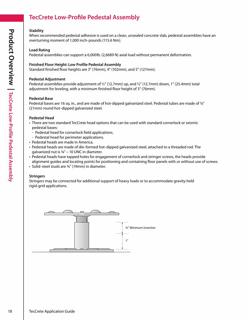
StabilityWhen recommended pedestal adhesive is used on a clean, unsealed concrete slab, pedestal assemblies have an overturning moment of 1,000 inch-pounds(115.6Nm).
Load RatingPedestal assemblies can support a 6,000lb.(2,6689N)axialloadwithoutpermanentdeformation.
Finished Floor Height: Low Profile Pedestal AssemblyStandardfinishedfloorheightsare3"(76mm),4"(102mm),and5"(127mm).
Pedestal AdjustmentPedestalassembliesprovideadjustmentof½"(12.7mm)up,and½"(12.7mm)down,1"(25.4mm)totaladjustmentforleveling,withaminimumfinishedfloorheightof3"(76mm).
Pedestal BasePedestalbasesare16sq.in.,andaremadeofhot-dippedgalvanizedsteel.Pedestaltubesaremadeof7/8"(21mm)roundhot-dippedgalvanizedsteel.
Pedestal Head• TherearetwostandardTecCreteheadoptionsthatcanbeusedwithstandardcornerlockorseismic pedestal bases: - Pedestal head for cornerlock field applications . - Pedestal head for perimeter applications .• PedestalheadsaremadeinAmerica.• Pedestalheadsaremadeofdie-formed hot-dippedgalvanizedsteel,attachedtoathreadedrod.The galvanizednutis3/4"–10 UNC in diameter .• Pedestalheadshavetappedholesforengagementofcornerlockandstringerscrews,theheadsprovide alignment guides and locating points for positioning and containing floor panels with or without use of screws .• Solid-steel studs are 3/4"(19mm)indiameter.
StringersStringers may be connected for additional support of heavy loads or to accommodate gravity-held rigid-grid applications .
3/4"MinimumInsertion
1"

TecCrete Application Guide 19
Product Overview
| Standard Cornerlock Understructure
Standard Cornerlock Understructure
Standardcornerlockpedestalsareusedtosupportfloorpanelsfor6"to68"(152mmto1727mm)finishedfloorheights . Standard cornerlock pedestals are used to support four panels by their corners . Perimeter heads support TecCrete panels that are used against a perimeter wall, or where two different types of floors meet .
3/4"–10UNCSteelStud
3/4"–10UNC2B AdjustingJamNut
7/8"(22mm)– Steel Tube
16 sq . in . Steel Base Plate
Also Available with Perimeter Head .
Standard pedestal bases are specified separately, for use with your choice of cornerlock field pedestal heads, or perimeter/transition pedestal heads.
Note

20 TecCrete Application Guide
Product Overview
| Pedestal Bases
Pedestal Bases
General InformationConstruction •Pedestalbasesaremadeofhot-dippedgalvanizedsteeltopreventzincwhiskers. •Pedestaltubesaremadeof7/8"(21mm)hot-dippedgalvanizedsteel. •Basesareatleast16"(406mm)square. •MadeinAmerica.Stability and Load Rating •To obtain overturning moment and axial load test values please contact your Haworth representative .Finished Floor Height •Finishedfloorheightsare6"to68"(152mmto1727mm).Otherheightsavailable.Pedestal Adjustment •Pedestalassembliesprovideanadjustmentrangeof±1"(25mm)whenfinished floorheightis6"(152mm)ormore,adjustableat1/64"(0.4mm)increments. •Minimumfinishedfloorheightis6"(152mm)forTecCrete1250/1500without stringers,or7"(178mm)forTecCrete1250/1500withstringers.TecCrete 2000/2500willbeaminimumof73/8"withstringers.Pedestal Head •TherearetwostandardTecCreteheadoptionsthatcanbeusedwithstandard cornerlock or seismic pedestal bases: - Pedestal head for field applications . - Pedestal head for perimeter applications . •Pedestalheadsaremadeofsteelwithbrightzincfinishattachedtoathreadedtube withagalvanized¾"diameter-10UNCnut. •Pedestalheadshavetappedholesforengagementofcornerlockandstringer screws, the heads provide alignment guides and locating points for positioning and containing floor panels with or without use of screws . •Solid-steelstudsare3/4"(19mm)indiameter.Head Options •Perimeterpedestalsarealsoavailabletosupportfloorpanelsadjacentto(Specified Separately) columns and walls .Stringers •Stringers may be connected for additional support of heavy loads, or to accommodate gravity-held rigid-grid applications . .
When stringers are used, pedestal bases must be specified 1" shorter for any floor height.Note
BASE FINISHED FLOOR mIN. FINISHED SqUARE BASE TUBE DIAmETER TUBE LENGTH PEDESTAL ADjUSTmENT TyPE HEIGHT RANGE FLOOR HEIGHT DImENSIONS (OUTSIDE) ADjUSTmENT INCREmENTS
Type 0 6" to 30" 6" 4" x 4" x 0 .0994" 0.875"square 3"to27" ±1" 1/64" (152mmto762mm) (152mm) (102mmx102mmx3mm) (22mm) (76mmto686mm) (±25mm) (0.4mm)
Type 1 6" to 30" 6" 5" x 5" x 0 .1853" 0 .875" square 3" to 27" ±1" 1/64" (152mmto762mm) (152mm) (102mmx102mmx5mm) (22mm) (76mmto686mm) (±25mm) (0.4mm)
Type 2 12" to 30" 12" 4" x 4" x 0 .0994" 1 .163" 9" to 27" ±1" 1/64" (305mmto762mm) (305mm) (102mmx102mmx3mm) (29.54mm) (229mmto686mm) (±25mm) (0.4mm)
Type 3 12" to 30" 12" 5" x 5" x 0 .1853" 1 .163" 9" to 27" ±1" 1/64" (305mmto762mm) (305mm) (127mmx127mmx5mm) (29.54mm) (229mmto686mm) (±25mm) (0.4mm)
Type 4 12" to 30" 12" 6" x 6" x 0 .1853" 1 .500" 9" to 27" ±1" 1/64" (305mmto762mm) (305mm) (152mmx152mmx5mm) (38.1mm) (229mmto686mm) (±25mm) (0.4mm)
Type 5 12" to 30" 12" 6" x 6" x 0 .25" 1 .500" 9" to 27" ±1" 1/64" (305mmto762mm) (305mm) (152mmx152mmx6mm) (38.1mm) (229mmto686mm) (±25mm) (0.4mm)
Pedestal Base Dimensions
TecCrete Application Guide 21
Product Overview
| Rigid Grid U
nderstructureRigid Grid Understructure
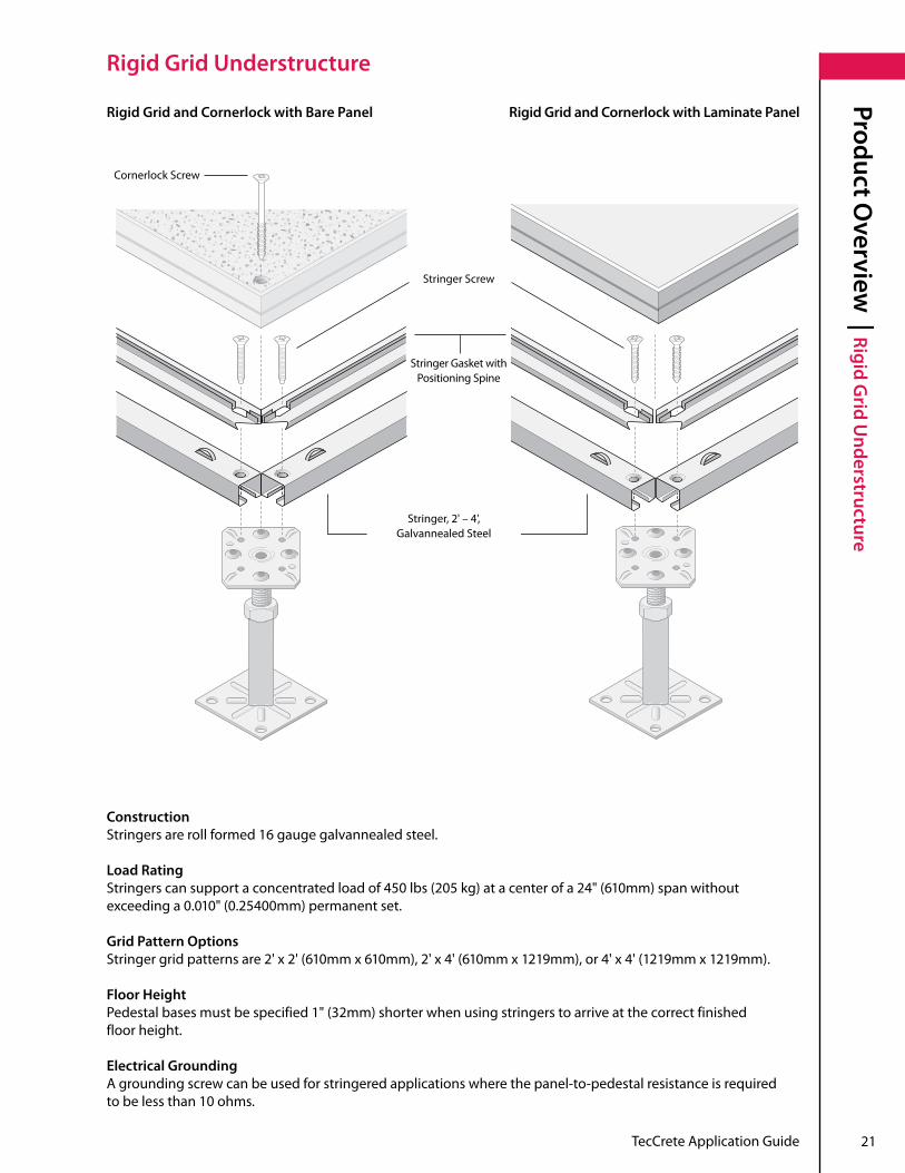
Stringer Gasket with Positioning Spine
ConstructionStringers are roll formed 16 gauge galvannealed steel .
Load RatingStringerscansupportaconcentratedloadof450lbs(205kg)atacenterofa24"(610mm)spanwithoutexceeding a 0 .010"(0.25400mm)permanentset.
Grid Pattern OptionsStringergridpatternsare2'x2'(610mm x 610mm),2'x4'(610mm x 1219mm),or4'x4'(1219mm x 1219mm).
Floor HeightPedestalbasesmustbespecified1"(32mm)shorterwhenusingstringerstoarriveatthecorrectfinished floor height .
Electrical GroundingA grounding screw can be used for stringered applications where the panel-to-pedestal resistance is required to be less than 10 ohms .
Cornerlock Screw
Rigid Grid and Cornerlock with Bare Panel Rigid Grid and Cornerlock with Laminate Panel
Stringer Screw
Stringer,2'–4', Galvannealed Steel

22 TecCrete Application Guide
Product Application | U
nderstructure Applications
Understructure Applications
Field Pedestal Attachment without Stringers
Field Pedestal Attachment Detailwithout Stringers
Field Pedestal Attachment Detailwith Stringers
Field Pedestal Attachment with Stringers
Stringer
Field Pedestal Head
AirSeal(optional)
Field Pedestal Head

TecCrete Application Guide 23
Product Application | U
nderstructure Applications
Understructure Applications
Perimeter Wall Condition without Stringers
Gasket is required for underfloor air applications (providedbyothers).
Apply pedestal adhesive between perimeterheadandcutpanel(optional).
Field HeadPerimeter Head
• Perimeterheadsshouldbelocatedasclosetotheedgeofthepanelaspossibleon24"centers,maximum.• Forplenumapplicationsnotutilizingcarpettileorstringers,anintegralairsealmaybespecifiedonpanelstooptimize underfloor air system performance.• Allapplicationdetailsapplytolowandstandardheight,exceptwherenoted.
Notes
Perimeter Wall Condition with Stringers
Gasket is required for underfloor air applications (providedbyothers).
Apply pedestal adhesive between perimeterheadandcutpanel(optional).
Field HeadPerimeter Head
For plenum applications, apply fire-rated caulk or sealant at the floor slab line to achieve a gapless air seal .
For plenum applications, apply fire-rated caulk or sealant at the floor slab line to achieve a gapless air seal .
Stringer
AirSeal(optional)

24 TecCrete Application Guide
Product Application | Cornerlockw
ithExpansionJointandExpansionJointDetail
CornerlockwithExpansionJointandExpansionJointDetail
ExpansionJointApplicationandDetailwithoutStringers
Curb Application without Stringers
Transition Plate (providedbyothers)
Apply pedestal adhesive between perimeterheadandcutpanel(optional).
ExpansionJointApplicationandDetailwithStringers
Expansion Joint (providedbyothers)
Expansion Joint (providedbyothers)
Concrete Expansion Joint
Concrete Expansion Joint
Apply pedestal adhesive between perimeterheadandcutpanel(optional).
Apply pedestal adhesive between perimeterheadandcutpanel(optional).
Curb Application with Stringers
Transition Plate (providedbyothers)
Apply pedestal adhesive between perimeterheadandcutpanel(optional).

TecCrete Application Guide 25
Product Application | Cornerlockw
ithExpansionJointandExpansionJointDetail
CornerlockwithExpansionJointandExpansionJointDetail
Fascia Application without Stringers
Fascia Application with Stringers
Fascia Plate
Fascia Plate
Note: Fasteners supplied by others .
Note: Fasteners supplied by others .
Apply pedestal adhesive between perimeterheadandcutpanel(optional).
Apply pedestal adhesive between perimeterheadandcutpanel(optional).
Fascia Top Angle
Fascia Top Angle
Fascia Bottom Angle
Fascia Bottom Angle
AirSeal(optional)

26 TecCrete Application Guide
Product Application | W
all Surface Partition and Doorw
ay Applications
Wall Surface Partition and Doorway Applications
Penetrating Wall without Stringers
Penetrating Wall with Stringers
Apply pedestal adhesive between perimeterheadandcutpanel(optional).
Apply pedestal adhesive between perimeterheadandcutpanel(optional).
Rubber gasket attached to curbtosealjoint.
Rubber gasket attached to curbtosealjoint.
Adhesive
Adhesive
For plenum applications, apply fire-rated caulk or sealant at the floor slab line to achieve a gapless air seal .
For plenum applications, apply fire-rated caulk or sealant at the floor slab line to achieve a gapless air seal .
For plenum applications not utilizing carpet tile or stringers, specify an integral air seal on panels to minimize cost and optimize underfloor air system performance.
Note
Stringer
AirSeal(optional)

TecCrete Application Guide 27
Product Application | W
all Surface Partition and Doorw
ay Applications
Wall Surface Partition and Doorway Applications
Surface Wall Partition Detail (without Stringers)
Steel Floor Track (providedbyothers)
Drywall Partition (providedbyothers)
Powder-actuated Fastener (providedbyothers;recommendedsizeis0.3"headwitha0.143"ODx0.75"shank)
Bolt(providedbyothers)
Alternativeattachmentmethod:Ifwallsaresecuredatceilinglevel,orstabilizedbyattachedperpendicularwalls,thenpowderactuatedpins(witha0.3"diameterhead and a 0 .143"diameter3/4"longshank),spacedat16-inch intervals, can be used to fasten floor track to the surface of the TecCrete panel .
Surface Wall Partition Detail (with Stringers)
Steel Floor Track (providedbyothers)
Drywall Partition (providedbyothers)
Large diameter washer and nut tighten to under side of raised floor panel .
Bolt(providedbyothers)
Alternativeattachmentmethod:Ifwallsaresecuredatceilinglevel,orstabilizedbyattachedperpendicularwalls,thenpowderactuatedpins(witha0.3"diameterhead and a 0 .143"diameter3/4"longshank),spacedat16-inch intervals, can be used to fasten floor track to the surface of the TecCrete panel .
For plenum applications not utilizing carpet tile or stringers, specify an integral air seal on panels to minimize cost and optimize underfloor air system performance.
Note

28 TecCrete Application Guide
Product Application | W
all Surface Partition and Doorw
ay Applications
Wall Surface Partition and Doorway Applications
Access Floor Interface at Glass Wall (without Stringers)
Window to Subfloor
Fascia Plate
Top Angle to Panel
Panel Cut to Suit
• Applypedestaladhesiveontopofflatpedestalheadandcutpanel.• Forplenumapplicationsnotutilizingcarpettileorstringers,anintegralairsealmaybespecifiedonpanelstooptimize underfloor air system performance.
Notes

TecCrete Application Guide 29
Product Application | W
all Surface Partition and Doorw
ay Applications
Wall Surface Partition and Doorway Applications
Access Floor Interface at Glass Doorway: Non-Stringer Application
Access Floor Interface at Glass Doorway: Stringer Application
Stringer
Door Pivot Embedded in Concrete (providedbyothers)
Poured Concrete Curb for Door Mounting
Perimeter Pedestal Support
Glass Doors (providedbyothers)
Door Pivot Embedded in Concrete (providedbyothers)
Poured Concrete Curb for Door Mounting
Perimeter Pedestal Support
Glass Doors (providedbyothers)

30 TecCrete Application Guide
Product Application | W
all Surface Partition and Doorw
ay Applications
Wall Surface Partition and Doorway Applications
Door Pivot Embedded in Concrete (providedbyothers)
Poured Concrete Curb for Door Mounting
Glass Door (providedbyothers)
Access Floor Interface at Glass Doorway Detail: Stringer Application

TecCrete Application Guide 31
Product Application | A
ngled Wall A
pplicationsAngled Wall Applications
Perimeter Condition at Angled Wall with Stringers
Perimeter Condition at Angled Wall without Stringers
Perimeter heads placed as close to the edgeaspossibleon24"centersmax.
Field Heads
Perimeter heads placed as close to the edgeaspossibleon24"centersmax.
Field Heads

32 TecCrete Application Guide
Product Application | Specialty Floor Finish A
pplications: Finish Transitions
Specialty Floor Finish Applications: Finish Transitions
Tile
Bare Panel
Underlayment
Thin-Set Mortar
Trim Strip
Bare Panel Application
Transition Trim (providedbyothers)
Ceramic Tile/Carpet with Trim Strip Transition

TecCrete Application Guide 33
Product Application | Specialty Floor Finish A
pplications: Finish TransitionsSpecialty Floor Finish Applications: Finish Transitions
Stringer
Cornerlock Pedestal Head
Transition from Cornerlock to Stringer-Supported Panels
Cornerlock Screws
Transition made Using Adjustable Head without Stringers
Surface Material (providedbyothers)
Transition made Using Adjustable Head with Stringers
Surface Material (providedbyothers)
Stringer

34 TecCrete Application Guide
Product Application | Floor A
rea Transitions
Floor Area Transitions
Transition Between Access Floor Levels
FasciaPlate(cuttosize)
Fastener(providedbyothers)
Aluminum Top Angle
Perimeter Head
Apply pedestal adhesive between perimeterheadandcutpanel(optional).
Perimeter Head
Full Panel
Steel Bottom Angle
Fastener(providedbyothers)
Transition Between Access Floor Levels: Steps
Aluminum Top AngleApply pedestal adhesive between perimeterheadandcutpanel(optional).
Diagonal Brace (providedbyothers)
Perimeter Head
Field Pedestal Head
Fastener (providedbyothers)
Fascia Plate (cuttosize)
Steel Bottom Angle
Full Panel
Steel Pedestal Base
Transition Between Access Floor Levels: Floor Supported
Aluminum Top Angle Apply pedestal adhesive between perimeterheadandcutpanel(optional).
Field Head
Perimeter Head
Perimeter Head
Fastener(providedbyothers)
Fastener(providedbyothers)
Fascia Plate (cuttosize)
Bottom Angle

TecCrete Application Guide 35
Product Application | Floor A
rea TransitionsFloor Area Transitions
Step Detail at Recessed Slab
Transition from Elevators/On-Slab Doorways
Pre-Fabricated Stairs (providedbyothers)
Elevator Door
Access Panel Fastened to Pedestals with Screws and Adhesive
Extra pedestal support located center of panel for high traffic area .Subfloor
PanelCuttoSize
For plenum applications not utilizing carpet tile or stringers, an integral air seal may be specified on panels to optimize underfloor air system performance.
• Applypedestaladhesivebetweenperimeterheadandcutpanel.• Forplenumapplicationsnotutilizingcarpettileorstringers,anintegralairsealmaybespecifiedonpanelstooptimize underfloor air system performance.
Note
Notes
For plenum applications, apply fire-rated caulk or sealant at the floor slab line to achieve a gapless air seal .
36 TecCrete Application Guide
Product Application | Floor A
rea Transitions
Floor Area Transitions
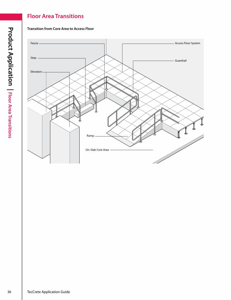
Transition from Core Area to Access Floor
Ramp
On-Slab Core Area
Step
Elevators
Fascia Access Floor System
Guardrail

TecCrete Application Guide 37
Product Application | Bridging O
bstructions on SubfloorsBridging Obstructions on Subfloors
Support(providedbyothers)
Obstruction
Support(providedbyothers) Tall Obstruction
Bridge Open Trench
Trench Bridging (providedbyothers)

38 TecCrete Application Guide
Product Application | Ram
p Details
Ramp Details
Swivel-Head Pedestal
Ramp Shoe
Ramp Threshold
Ramp without Stringers
1:12(4degree)slopeRamp Shoe
72"

TecCrete Application Guide 39
Product Application | m
ounting Equipment to TecCrete A
ccess Floorsmounting Equipment to TecCrete Access Floors
mounting Equipment to Access Floors without Stringers
mounting Equipment to Access Floors with Stringers
Stringer

40 TecCrete Application Guide
Product Application | m
ounting Equipment to TecCrete A
ccess Floors
mounting Equipment to TecCrete Access Floors
mounting Equipment to Subfloors without Stringers
Access Floor Panel
ThreadedRod/Turnbuckle
Hex Head Nut, Washer, Lock Washer
Spring Nut
Unistrut mounted to subfloor per manufacturer’sinstructions.
Hex Head Nut, Washer, Lock Washer
mounting Equipment to Subfloors with Stringers
Access Floor Panel
ThreadedRod/Turnbuckle
Hex Head Nut, Washer, Lock Washer
Spring Nut
Unistrut mounted to subfloor per manufacturer’sinstructions.
Hex Head Nut, Washer, Lock Washer Stringer
TecCrete Application Guide 41
Product Application | m
ounting Equipment to TecCrete A
ccess Floorsmounting Equipment to TecCrete Access Floors
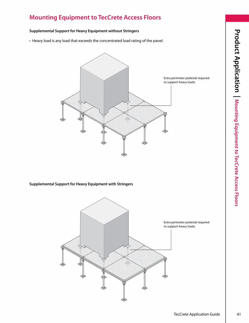
Supplemental Support for Heavy Equipment without Stringers
• Heavyloadisanyloadthatexceedstheconcentratedloadratingofthepanel.
Extra perimeter pedestal required to support heavy loads .
Extra perimeter pedestal required to support heavy loads .
Supplemental Support for Heavy Equipment with Stringers

42 TecCrete Application Guide
Product Application | Fire and Safety A
pplications
Fire and Safety Applications
Handrail Assemblies
Fire Barrier at Door Threshold
Perimeter Pedestal Support
Structural Wall Channels
Sheetrock-Faced Fire Barrier
Wall-Mounted Handrail
Return Rail
Hand Rail (providedbyothers)
Ramp
Optional Threshold Structural Wall Channels
Top of Access Floor

TecCrete Application Guide 43
Product Application | Fire and Safety A
pplicationsFire and Safety Applications
Air Duct Through a Firewall
Thru-Slab Sprinkler Detail
Main Water Loop for Sprinkler System Access Floor System
Fire Sealant
Pedestals
Air DuctFire Damper
Fire Stop Material
Main Water Loop for Sprinkler System
For plenum applications not utilizing carpet tile or stringers, an integral air seal may be specified on panels to optimize underfloor air system performance.
Note
44 TecCrete Application Guide
Product Application | Bathroom
Applications
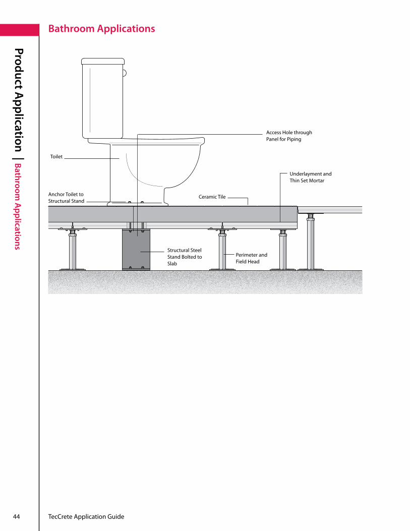
Bathroom Applications
Access Hole through Panel for Piping
Toilet
Anchor Toilet to Structural Stand
Structural Steel Stand Bolted to Slab
Underlayment and Thin Set Mortar
Ceramic Tile
Perimeter and Field Head

TecCrete Application Guide 45
Product Application | Electrical A
pplicationsElectrical Applications
ElectricalBoxinFloor
TecCrete Conductive Path to Ground without Stringers
TecCrete Conductive Path to Ground with Stringers
• Barepanelconductivepathtoground:acornerlockscrewconnectsthesteelpantothepedestalheadwhichisconnectedto the pedestal base — creating a ground path.• Coveredpanelconductivepathtoground:conductivesurfaceandconductiveadhesivecontacttheTecCretesteelpanwhich contacts the grounding screw. The grounding screw is attached to the stringer which is also connected to the pedestal head and base — creating a ground path.
Notes
TecCrete Steel Pan
Conductive Surface and Conductive Adhesive
Pedestal Head
Stringer
Grounding Screw
Pedestal Base
TecCrete Steel Pan
Pedestal Head
Cornerlock Screw
Pedestal Base

46 TecCrete Application Guide
Product Application | Controlling A
ir Leakage
Controlling Air Leakage
TecCrete access flooring is often used to create an underfloor cavity for air distribution . When TecCrete is applied in this way, care must be taken to prevent unintentional air leakage from the underfloor cavity into the occupied space . UnintentionalairleakageoccurswhenpressurizedairfromanHVACsystementerstheenvironmentfromsources other than the air diffusers . These sources can include gaps at access floor perimeters, columns, wall and slab openings, and around conduits, pipes and other obstructions . Although a properly installed access floor will minimizethepossibilityofunintentionalairleakage,itisimportanttokeepaircontrolinmindduringallphases of building construction and access floor installation . When each trade does its part to maintain the overall condition of subfloors, access floors, building cavities, and air passage points, the end result will be a well-sealed environment with minimal air leakage .
Air Tightness Specification TecCrete access floor panels show exceptional air control properties . TecCrete specifications are twice as high as those of typical die-cut floor panels .
TecCrete Air Tightness PerformanceTecCrete panels, with and without installed carpet tiles, have shown exceptional air leakage control in laboratory tests .
AirDistributionSystemStaticPressure 0.05" 0.10" TecCretePanelBareFloorwithAirSealLeakRates 0.36CFM/sq.ft. 0.44CFM/sq.ft. TecCretePanelwithSolid-BackedCarpetTiles–LeakRates 0.04CFM/lin.ft. 0.04CFM/lin.ft.
AirDistributionSystemStaticPressure 0.05" 0.10" TecCrete floor panel with carpeted surface No greater than 0 .10CFM/sq.ft Nogreaterthan0.10CFM/sq.ft
The leak rates do not include leakage at floor perimeters; the carpet tiles overlapped the panel seams in the tests.Note
Leak rates do not include leakage at floor perimeters.Note

TecCrete Application Guide 47
Product Application | Controlling A
ir LeakageControlling Air Leakage
Controlling Air Leakage During Construction and Access Floor Installation
TherearemanywaystoeffectivelypreventunintentionalairleakageinaTecCreteaccessfloorinstallation. Your general contractor should make sure that every slab-to-ceiling wall fits tightly and is correctly sealed at the slab-line before access flooring is installed . Irregular wall surfaces may require gaskets, caulking, or tape to properly seal access floor-to-wall connections . Building contractors must completely seal cavity seams where walls rest on subfloors, and where access flooring connects with slab-to-ceiling walls, columns and other obstructions .
It is also important that all utility access points — such as openings for air ducts, conduits, cables, and pipes —becarefullysealed.Allopeningsinbuildingelementsforplumbing,electricityandvoice/datacablingmustbe sealed by the trades that do those installations and should be inspected before access floors are installed . If additional openings are cut for utilities after the access floor is installed, those should be inspected for seal quality before carpet tiles are installed . Your carpet installer also plays an important role in ensuring proper air sealing by fitting carpets snugly against wallsandotherverticalsurfaces,andbyconsistentlyoverlappingfloorpaneljointswithcarpettiles.Extendingcarpet tiles all the way to the wall, carefully fitting perimeter panels, and tightly installing wall bases, all help to seal access floor perimeters .
For plenum applications not utilizing carpet tile or stringers, an integral air seal may be specified on panels to optimize underfloor air system performance.
Note

48 TecCrete Application Guide
Product Application | Proper A
ir Sealing Before and During A
ccess Floor Installation
Proper Air Sealing Before and During Access Floor Installation
At Perimeters:
Seals at flat perimeter walls and surfaces: • Allwallspassingthroughtheaccessfloormustextendcompletelytotheslabandbesealedattheslabline. Floor panels should fit to within 1/16” of perimeter walls, columns, and other vertical surfaces . • Ifcarpettilesareused,theymustalsobecuttofittightlyagainstperimeterwallsandsurfacesasanadditional layer of airseal protection . • Wallbasesshouldbeinstalledtightlyagainstcarpetandaccessfloortocoverjoints.
Seals at non-flat perimeter walls or other surfaces: • Floorpanelsshouldfittowithin1/16” of perimeter walls . • Ifthewalldoesnothaveacompletelyflatsurfacebecauseitisshaped,textured,orslightlyirregular,foam strips or rubber tape can be mounted flush with the floor surface to fill in gaps . • Theuseofcaulkorsealanttofilljointsbetweenfloorpanelsandverticalsurfacesisalsoanoption.Usingcaulk or sealant instead of carpet adhesives will allow for easier removal of access floor panels later . • Ifcarpettilesareused,theymustalsobecuttofittightlyagainstperimeterwallsandsurfacesasanadditional layer of airseal protection . • Wallbasesshouldbeinstalledtightlyagainstcarpetandaccessfloortocoverjoints.
Sealsatfasciaorexposededges:• Fasciaplatesshouldbecuttoalignwiththetopsoffloorpanels.• Ifthereareanygapsbetweenfloorpaneltopedgesandfascia,ducttape,ormetaltapecanbeusedtocover thejointsbeforecarpetinstallation.• Ifcarpettilesareused,theymustalsobecuttofitallthewayoverfascia.Fasciaandcarpettilesshouldbe covered by angle trim pieces for airseal protection .
A BC
D
E
F
G
H
I
J
K
L
M
A
B
C

TecCrete Application Guide 49
Product Application | Proper A
ir Sealing Before and During A
ccess Floor InstallationProper Air Sealing Before and During Access Floor Installation
Seals at curb interfaces:• Whenaccessfloorcoveringsextendallthewaytothecurb,cutthefloorpanelstowithin1/16"ofperimeter.• Attachsealingfoamorrubbertapetothecurbifagapexceeds1/16"beforefloorpanelsareinstalled.• Installcarpettilesbyoverlappingfromaccessfloortocurb.• Whenaccessfloorcoveringsdonotextendallthewaytothecurb,cutthefloorpanelstowithin1/16" of perimeter .• Attachsealingfoamorrubbertapetothecurbifagapexceeds1/16"beforefloorpanelsareinstalled.• Installcarpettilesbyoverlappingfromaccessfloortocurb.• Sealthejointwithatransitionstriporthresholdattop.
Seals at utility access points
Seals at cable cutouts: • Cutfoamtofitsnuglyintoopeningsandsupportledges.• Installmanufacturer'strimforcablecutouts.
Seals at plenum dividers: • Cutopeningsintotheplenumdividerthataresizedforthedimensionsoftheducts,pipes,conduit,andcable bundles that need to pass through . • Ifthereareanygaps,ducttape,ormetaltapecanbeusedtofillthembeforeaccessfloorinstallation.• Allgapsinbuildingarchitectureshouldbesealedandinspectedbeforetheaccessfloorisinstalled.
Seals at pipe openings through access flooring: • Cutopeningsintotheaccessfloorsizedspecificallyforthediametersofthepipesthatneedtopassthrough.• Sealsatsubfloorpipeopenings.• Sealgapsaroundpipeswithcaulkorsealantwithfirestopsystemmaterialsbeforeinstallingtheaccessfloor.
Seals at fire barriers
Seals at firewall utility access points: • Whereverthereisagapbetweenducts,pipes,conduitsorcablebundles,andtheopeningscutintofirewallsto accommodate utility access, fill the gaps with approved firestop system materials . • Allgapsinbuildingarchitectureshouldbesealedandinspectedbeforetheaccessfloorisinstalled.
Seals at firewalls at the access floor: • Floorpanelsshouldfittowithin1/16"ofperimeterwalls,columns,andotherverticalsurfaces.• Ifcarpettilesareused,theymustalsobecuttofittightlyagainstperimeterwallsandsurfacesasanadditional layer of airseal protection . • Wallbasesshouldbeinstalledtightlyagainstcarpetandaccessfloortocoverjoints.
Seals at access floors at fire barrier below door threshold: • Floorpanelsshouldbecuttofittowithin1/16"ofthefirebarrier.• Jointscanbesealedbyinstallingathresholdplatewithagasketattachedtothebottom.• Anotheroptionforsealingjointsistoattachagaskettotheverticalsurfaceofthefirebarrierandfloorpanels.• Athirdoptionistoinstallfloorpanelsanduseafire-ratedcaulkorsealanttofillanygapsbetweenthepanels and the fire barrier . • Ifcarpettilesareused,theymustalsobecuttofittightlyagainstperimeterwallsandsurfacesasanadditional layer of airseal protection .
Seals at firewalls at the subfloor:• Sealthefirewallalongtheslab-line with fire-rated caulk or sealant that has rating equal to that of the wall assembly before installing access flooring .
D
E
F
G
H
I
J
K
L
M
Please refer to the TecCrete installation instructions for more detailed information. Note

50 TecCrete Application Guide
Without Stringer
Plenum Divider (providedbyothers)
Fasteners (providedbyothers)
Closed-cell foam gasket with pressure-sensitiveadhesive;onesideonly.Applytotop flange .
Add Plenum Rated Sealing Material
Note: Plenum divider may be located anywhere under the panel due to flat underside of panel .
Product Application | Plenum
Applications
Plenum Applications
With Stringer
Two Piece Steel or Aluminum Plenum Divider (providedbyothers)
Note: Plenum divider may be located anywhere under the panel due to flat underside of panel .
Fasteners (providedbyothers)
Add Plenum Rated Sealing Material
Add Plenum Rated Sealing Material

TecCrete Application Guide 51
Product Application | Plenum
and Air H
ighway A
pplicationsPlenum and Air Highway Applications
Plenum Divider/Plenum Divider Detail
View A Detail: Side View
Panel
GalvanizedSteelPlenum Divider (providedbyothers)
Subfloor
TecCrete Air Seal Required Only for Bare Applications
Seal with Plenum-rated caulk sealant or tape as required .
Closed-cell foam gasket with pressure-sensitiveadhesive;oneside only . Apply to top flange .
ViewA

52 TecCrete Application Guide
Product Application | Plenum
and Air H
ighway A
pplications
TecCrete 1250 with 2 plenums
Air seal should be used in a bare panel installation . No air seal is required if the panel will be covered with another material .
Add plenum rated sealing material top and bottom .
PanelNo air seal is required when ducting is used .
Subfloor
GalvanizedSteelPlenumDivider (providedbyothers)
Subfloor
HVACDuct
Plenum and Air Highway Applications
Air Highway: Interior
TecCrete Application Guide 53
Product Application | Plenum
and Air H
ighway A
pplicationsPlenum and Air Highway Applications
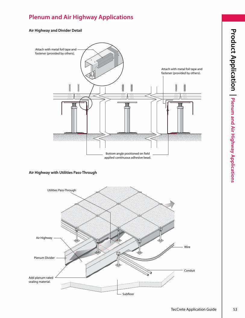
Air Highway and Divider Detail
Air Highway with Utilities Pass-Through
Attach with metal foil tape and fastener(providedbyothers).
Attach with metal foil tape and fastener(providedbyothers).
Bottom angle positioned on field applied continuous adhesive bead .
Utilities Pass-Through
Subfloor
Plenum Divider
Air Highway
Add plenum-rated sealing material .
Conduit
Wire

54 TecCrete Application Guide
Product Application | Plenum
and Air H
ighway A
pplications
Plenum and Air Highway Applications
Plenum Zone Divider Detail• TecCrete’sflatpanelundersidedeliversagaplesssealnomatterwhereaplenumdividerispositionedunder the panel .
GalvanizedSteelPlenumDividerPanel(providedbyothers)
Tapejointswithmetalfoiltapewhere bottom angle sections and channel sections meet .
Bottom Angle positioned in field . Apply continuous adhesive bead .

TecCrete Application Guide 55
Product Application | Plenum
and Air H
ighway A
pplicationsPlenum and Air Highway Applications
Penetration through Plenum Divider
Air Seal Detail (optional)
Plenum Divider Assembly
Seal to Fill Gap
For plenum applications not utilizing carpet tile or stringers, an integral air seal may be specified on panels to optimize underfloor air system performance.
Note

56 TecCrete Application Guide
This page intentionally left blank .

Electrical Overview
| IntroductionElectrical Overview: Introduction
57TecCrete Application Guide

58 TecCrete Application Guide
Our Philosophy On Electrical
Electrical Overview
| Our Philosophy on Electrical
Haworth has a unique approach when it comes to Electrical Distribution and its ever changing layout . Our philosophy is to design and install for tomorrow rather than conventionally wiring for today . How do we do that? By runningeverythingrightbeneathyourfeetusingplug-and-playtechnologyandazonedistributionmethodologythat delivers power to where the customer needs it . This ensures that your electrical infrastructure will be able to respondtotoday'sfastpaceandfastrateofchange.Beingflexibletodayiscriticaltotomorrow’ssurvival.
Reconfiguring should be fast, growing should be easy, and with Haworth Power Base AI, it is . Our quick-connect systems power you up . . .fast! Haworth offers Power Base AI, a modular power system for raised floor applications, which helps to ensure quick installationandfutureflexibility.Quickinstallationreducesconstructionscheduleriskandcontrolsjobsitelaboroverruns . Future flexibility helps increase tenant satisfaction and lowers operating and renovation costs . HaworthhasdevelopedtwopowerdistributionsystemstoaccommodatetheelectricalneedsofallmajorNorthAmerican office furniture manufacturers: The 3-Circuit and the 4-Circuit systems . Each has been specifically designed for use in Haworth Access Flooring and is based on plug-and-play connectivity . The 3-Circuit separate neutral system provides individual branch circuits for power quality and multiple power sourceflexibilitynotavailablein4-Circuitapplications.The4-Circuitsharedneutralversionhelpstomaximizethenumber of circuits while staying within the common ½"tradeconduits.ThismodularpowersystemisULListed,CSA Certified, and complies with NEC Article 604 . The Power Base AI system consists of six main elements to distribute power . They include the following: • ZoneDistributionBox • Jumper• Splitter • ServiceModule• ModularReceptacle • HaworthPlug-and-PlayFurnitureBaseFeed
Power Input from Electrical Closet
Splitter(4-Port)
Jumpers
1-Port Zone Distribution Box
Infeed Harness
Column Feed
Splitter(2-Port)
InfeedSystem
Furniture Top Feed
Power Base AI Equipped Moveable Wall
Power Base AI Equipped Service Pole
Power Base AI Equipped Poke
Through
Infeed Harness
Above Ceiling Application
TecCrete Application Guide 59
System OverviewElectrical O
verview | System
Overview
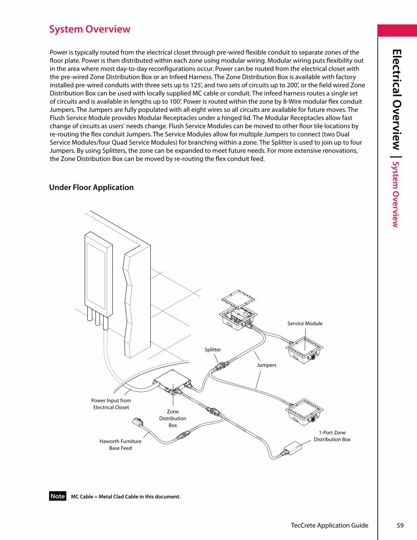
Poweristypicallyroutedfromtheelectricalclosetthroughpre-wiredflexibleconduittoseparatezonesofthefloorplate.Poweristhendistributedwithineachzoneusingmodularwiring.Modularwiringputsflexibilityoutin the area where most day-to-day reconfigurations occur . Power can be routed from the electrical closet with the pre-wired Zone Distribution Box or an Infeed Harness . The Zone Distribution Box is available with factory installed pre-wired conduits with three sets up to 125', and two sets of circuits up to 200', or the field wired Zone Distribution Box can be used with locally supplied MC cable or conduit . The infeed harness routes a single set ofcircuitsandisavailableinlengthsupto100'.Powerisroutedwithinthezoneby8-WiremodularflexconduitJumpers . The Jumpers are fully populated with all eight wires so all circuits are available for future moves . The Flush Service Module provides Modular Receptacles under a hinged lid . The Modular Receptacles allow fast change of circuits as users' needs change . Flush Service Modules can be moved to other floor tile locations by re-routingtheflexconduitJumpers.TheServiceModulesallowformultipleJumperstoconnect(twoDualServiceModules/fourQuadServiceModules)forbranchingwithinazone.TheSplitterisusedtojoinuptofourJumpers.ByusingSplitters,thezonecanbeexpandedtomeetfutureneeds.Formoreextensiverenovations,the Zone Distribution Box can be moved by re-routing the flex conduit feed .
mC Cable = metal Clad Cable in this document.Note
Power Input from Electrical Closet
Haworth Furniture Base Feed
Zone Distribution
Box
Splitter
Jumpers
Service Module
1-Port Zone Distribution Box
Under Floor Application

60 TecCrete Application Guide
Statement of Line: Power Base AI
Electrical Overview
| Statement of Line: Pow
er Base AI
Field-Wired 1-PortZone Distribution Box
3-and4-Circuit
Pre-Wired 3-PortZone Distribution Box
Pre-Wired 2-PortZone Distribution Box
Field-Wired 3-PortZone Distribution Box
Jumper5', 10', 15', 20', 35', or 50' Long
4-Port Splitter 2-Port SplitterInfeed Harness15",10',25',50',75',or100'Long
Quad Service Module (Field-Wired)
Dual Service Module (Field-Wired)
Hardwire
Dual Service ModuleQuad Service Module Modular Receptacle (20AmpDuplex)
Modular Receptacle(15AmpDuplex)

TecCrete Application Guide 61
Statement of Line: Power Base AIElectrical O
verview | Statem
ent of Line: Power Base A
I
Service Module Lid Service Module Lid and Trim Ring Cord Manager Loop
PREMISE®,Moxie®,andCompose™Floor Infeed
PLACES®, UniGroup®, and Tactics®Floor Infeed Floor Infeed
RACE® Single Harness Connector
Accessories

62 TecCrete Application Guide
Electrical Overview
| Typical Power Base A
I Application
Typical Power Base AI Application
UsingPowerBaseAIwithEnclose®orLifeSPACE®allowsformaximumflexibilityinreconfiguration of office space:
• To move an Enclose or LifeSPACE panel a short distance, simply move the panel to any new location within thejumpercablelength.• Whenreconfigurationrequiresanewlayout,simplydisconnectthejumperfromtheEncloseorLifeSPACE panel and Zone Distribution Box, move the Enclose or LifeSPACE panel to the new location, and reconnect the jumpertotheEncloseorLifeSPACEpanelandZoneDistributionBox.
• Allgroundfaultcircuitinterrupter(GFI)outletsmustbehardwired.IfusingLifeSPACE® electrical panels, the installation drawings for the wall panels and Power Base AI must be coordinated.
• Formoreinformation,pleasesee“ApplicationGuidelines”onpages23-25ofHaworth’sPowerBaseAIApplicationGuide.
Notes

TecCrete Application Guide 63
This page intentionally left blank .
64 TecCrete Application Guide
Voice and Data O
verview | Pre-Term
inated Zone Voice and Cabling
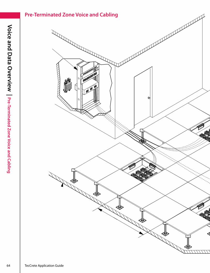
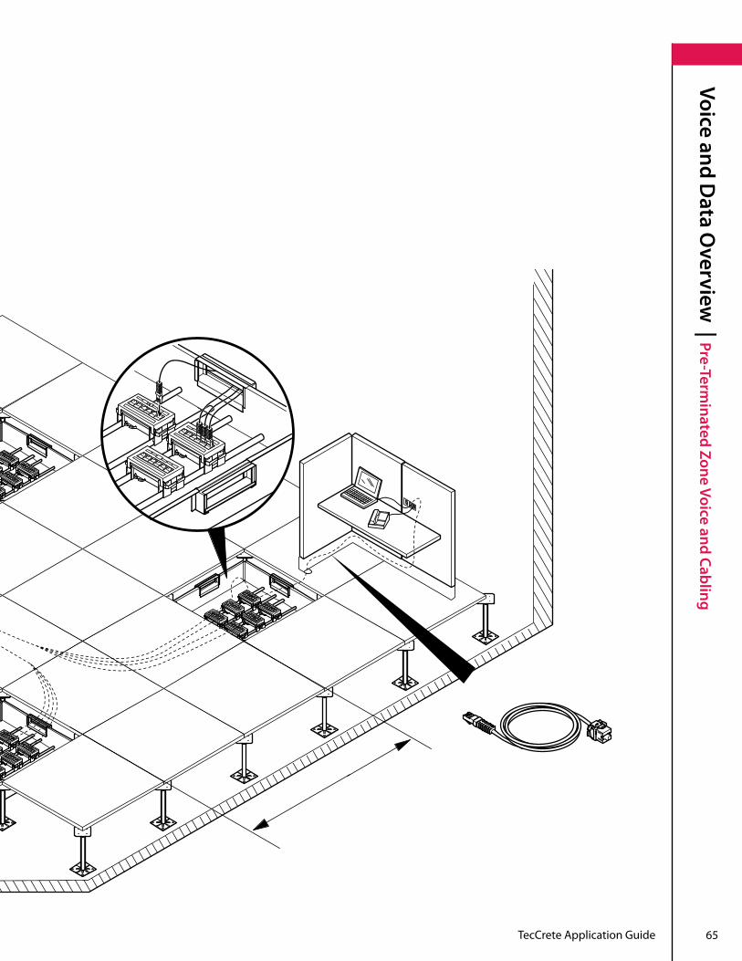
Pre-Terminated Zone Voice and Cabling
TecCrete Application Guide 65
Voice and Data O
verview | Pre-Term
inated Zone Voice and Cabling

66 TecCrete Application Guide
Voice and Data O
verview | Statem
ent of Line: Pre-Terminated Zone
Statement of Line: Pre-Terminated Zone
Rack Universal Mounting Bracket
48-Port Patch Panel
External Consolidation Point
12-Port Zone Consolidation Box
Plenum Box with UMS Patch Panels
Haworth offers Pre-TerminatedZoneVoiceandDataforaccessfloorapplicationswhichhelptoensurequickinstallation, future flexibility, reduced construction schedules, increased tenant satisfaction and lower operating and renovation costs . Haworth's product solutions for voice and data include many familiar components in the following five categories:
1. Standard Components: 7' Equipment Racks, Patch Panels, and Ring Wire managers
2. Standard Horizontal Cabling: Communication Cabling and Consolidation PointsCommunicationcabling(Cat5eorCat6)thatisroutedthroughtheceilingorfloortoaconsolidationpoint(UMSPatchPanels,Ultim8,etc.).Itisavailableinnon-plenumandplenumratedjacket.
3. Pre-Terminated Zone Consolidation PointsAvailable products include 12-portzoneconsolidationbox,UMSpatchpanels,24- and 48-port patch panels, and external consolidation point housings . In addition, a plenum box is available for air handling applications . Each type of consolidation point device acts as a modular connection point for outlet taps .
TecCrete Application Guide 67
Voice and Data O
verview | Statem
ent of Line: Pre-Terminated Zone
Statement of Line: Pre-Terminated Zone
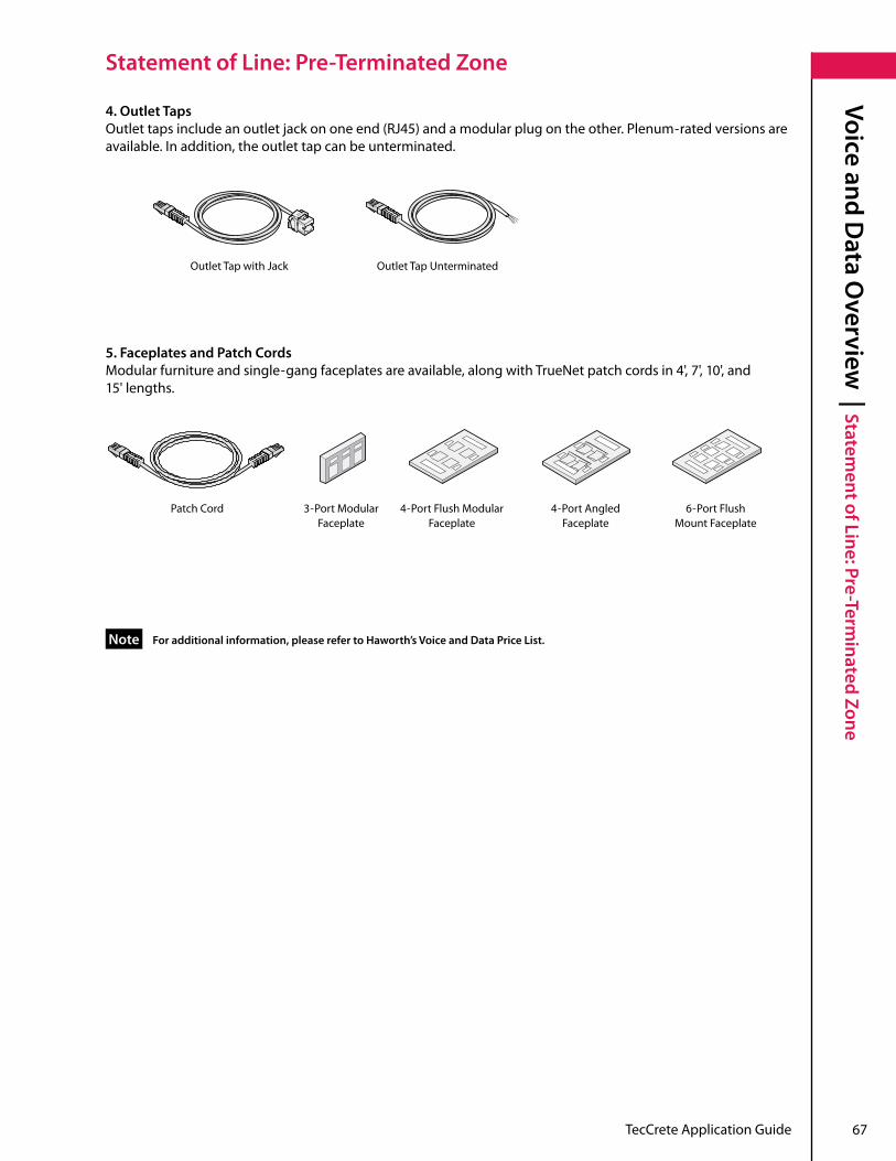
5. Faceplates and Patch CordsModular furniture and single-gang faceplates are available, along with TrueNet patch cords in 4', 7', 10', and 15' lengths .
Outlet Tap with Jack Outlet Tap Unterminated
Patch Cord 3-Port Modular Faceplate
4-Port Flush Modular Faceplate
4-Port Angled Faceplate
6-Port Flush Mount Faceplate
4.OutletTapsOutlettapsincludeanoutletjackononeend(RJ45)andamodularplugontheother.Plenum-rated versions are available . In addition, the outlet tap can be unterminated .
Foradditionalinformation,pleaserefertoHaworth’sVoiceandDataPriceList.Note
LEED®-N
C 3 | Introduction
68 TecCrete Application Guide
Introduction
TecCrete® Contributions Toward Meeting LEED®-NC 3
TecCreteAccessFlooringcanplayanimportantroleinprojectsthatareseekingcertificationundertheLEEDforNew Construction rating system .
Key considerations include:
Air quality. The materials in TecCrete products do not adversely impact indoor air quality . Also, the concrete top surface of TecCrete can be sealed with low-or-noVOCsealers.
Design for Environment (DfE). TecCrete is a very durable product that is 100% reusable . Designing product that maximizestheyearsofusefullifeisoneofmanystrategiesrelatedtoDesignforEnvironment(DfE).
Recycled Content. TecCrete product contains recycled content materials . Steel pedestals are 25-30% recycled content and steel pans are 80% recycled content .
Because LEED is a holistic building rating system and sustainable design guideline, there is no such thing as a LEED-certifiedproduct;thereareonlywaysofusingandapplyingproductstomeetLEEDcriteria.Insomecases,TecCrete product contributes directly to individual LEED points, but in other cases can only help contribute to the overall intent of the point . There are relatively few instances where selection of any one product from any manufacturerwillleaddirectlytoacquisitionofapoint(s)underLEED.
TheinformationprovidedbelowdiscussesdirectimpactsaswellasapplicationtipsandstrategiestomaximizethecontributionofTecCreteproductstowardtheirproject’sLEEDcertification.
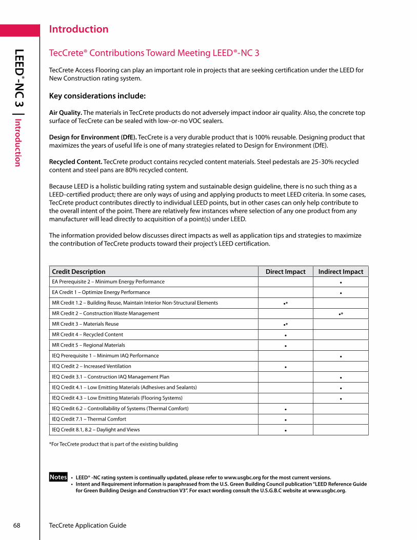
Credit Description Direct Impact Indirect ImpactEAPrerequisite2–MinimumEnergyPerformance •EACredit1–OptimizeEnergyPerformance •MRCredit1.2–BuildingReuse,MaintainInteriorNon-StructuralElements •*MRCredit2–ConstructionWasteManagement •*MRCredit3–MaterialsReuse •*MRCredit4–RecycledContent •MRCredit5–RegionalMaterials •IEQPrerequisite1–MinimumIAQPerformance •IEQCredit2–IncreasedVentilation •IEQCredit3.1–ConstructionIAQManagementPlan •IEQCredit4.1–LowEmittingMaterials(AdhesivesandSealants) •IEQCredit4.3–LowEmittingMaterials(FlooringSystems) •IEQCredit6.2–ControllabilityofSystems(ThermalComfort) •IEQCredit7.1–ThermalComfort •IEQCredit8.1,8.2–DaylightandViews •
*For TecCrete product that is part of the existing building
• LEED® -NC rating system is continually updated, please refer to www.usgbc.org for the most current versions.• IntentandRequirementinformationisparaphrasedfromtheU.S.GreenBuildingCouncilpublication“LEEDReferenceGuide forGreenBuildingDesignandConstructionV3”.ForexactwordingconsulttheU.S.G.B.Cwebsiteatwww.usgbc.org.
Notes
TecCrete Application Guide 69
LEED®-N
C 3 | Energy and Atm
osphereEnergy and Atmosphere
EA Prerequisite 2: minimum Energy Performance
Intent• Establishtheminimumlevelofenergyefficiencyfortheproposedbuildingandsystems.
How TecCrete Helps meet This Requirement• TecCreteAccessFlooringenablesunderfloorairdistribution,whichhasbeenshowntoreducetheenergycosts required for cooling interior spaces by 5%-30%, thus helping to reduce the overall design energy cost of the building .
EA Credit 1: Optimize Energy Performance (1-10 pts)
Intent• Achieveincreasinglevelsofenergyperformanceabovetheprerequisitestandardtoreduceenvironmental impacts associated with excessive energy use .
How TecCrete Helps meet This Requirement• TecCreteAccessFlooringenablesunderfloorairdistribution,whichhasbeenshowntoreducetheenergy costsrequiredforcoolinginteriorspacesby5%–30%,thushelpingtoreducetheoveralldesignenergycostof the building .
IntentandRequirementinformationisparaphrasedfromtheU.S.GreenBuildingCouncilpublication“LEEDReferenceGuide forGreenBuildingDesignandConstructionV3”.ForexactwordingconsulttheU.S.G.B.Cwebsiteatwww.usgbc.org.
Note

70 TecCrete Application Guide
LEED®-N
C 3 | materials and Resources
materials and Resources
mR Credit 1.2: Building Reuse (1-2 pts) • Maintain75%(100%)ofInterior,Non-StructuralElements
Intent• Extendthelifecycleofexistingbuildingstock,conserveresources,retainculturalresources,reducewaste,and reduce environmental impacts of new buildings as they relate to materials manufacturing and transport .
How TecCrete Helps meet This Requirement• ContributiontothiscreditisdependentonTecCretebeingpartofthepriorstructure.However,addingTecCrete andmodularpoweranddatasystemswillcreatevalueforbuildingsthatpursueLEEDforfuturemajorupdates.• Raisedfloorsaretypicallyleftintact,withallchangestowallsoccurringbetweentheraisedfloorandtheceiling.• TecCreteis100% reusable . It is designed for easy disassembly and movement from one space to another . The ability to reuse building materials significantly reduces budgets for new spaces, with an equivalent decrease in resource demands .• Underfloorairdistributionsystemsareinherentlyreusable.Tileswithdiffusersneedonlyberelocated,and not discarded and replaced in order to accommodate changes in mechanical loads . In addition, underfloor air distributionreducestheneedforductwork(upto80%lessductworkthanconventionalHVAC),sochangesto the cooling system do not generate additional waste .• FlooringfinishesusedwithHaworthraisedfloors,suchascarpet,arealsomodulartilesystems,whichcanbe removed and re-laid in new configurations and locations .• ThoughnotrecognizedyetbyLEEDfortheinitialinstallation,raisedfloorsminimizelifecyclecostsandaddress future material conservation and reuse . This will create value for buildings which pursue LEED for future majorupdates.
mR Credit 2: Construction Waste management (Divert from Disposal 50% [1pt] / 75% [2pts)
Intent• Divertconstructionanddemolitiondebrisfromdisposalinlandfillsandincinerationfacilities.Redirect recyclable recovered resources back to the manufacturing process and reusable materials to appropriate sites .
How TecCrete Helps meet This Requirement• TecCretedoesnotdirectlyimpactthispoint.However,wastereductionthroughintelligentdesigncandecrease the amount of construction waste generated in installation and prevent additional waste generation during changes to the space or when moving to a new space .• Modularpoweranddatasystemsusedwithaccessflooringallowtheinstallationoftechnologyinfrastructure withnearzerowaste.Thiseliminatesconduit,electricalwiring,anddatawiringwaste.• Raisedfloorsystemsgenerateverylittleconstructionwaste,withonlyafewtilesthatneedtobetrimmedto sizeorneedtohavepenetrationsinstalledon-sitethatgeneratescrap.Eventhiswastecanbeminimizedwith careful planning . • TecCreteisalso100% reusable, eliminating waste on future reconfigurations .
IntentandRequirementinformationisparaphrasedfromtheU.S.GreenBuildingCouncilpublication“LEEDReferenceGuide forGreenBuildingDesignandConstructionV3”.ForexactwordingconsulttheU.S.G.B.Cwebsiteatwww.usgbc.org.
Note
TecCrete Application Guide 71
LEED®-N
C 3 | materials and Resources
materials and Resources
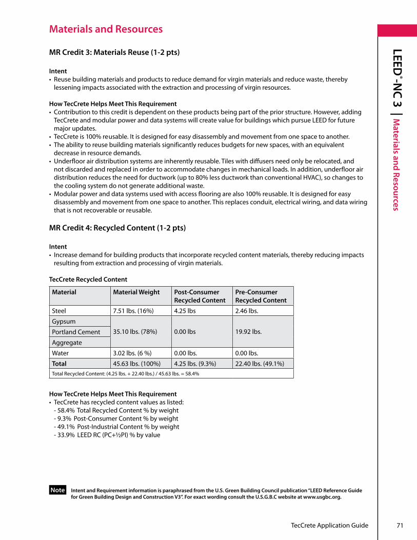
mR Credit 3: materials Reuse (1-2 pts)
Intent• Reusebuildingmaterialsandproductstoreducedemandforvirginmaterialsandreducewaste,thereby lessening impacts associated with the extraction and processing of virgin resources .
How TecCrete Helps meet This Requirement• Contributiontothiscreditisdependentontheseproductsbeingpartofthepriorstructure.However,adding TecCrete and modular power and data systems will create value for buildings which pursue LEED for future majorupdates.• TecCreteis100% reusable . It is designed for easy disassembly and movement from one space to another .• Theabilitytoreusebuildingmaterialssignificantlyreducesbudgetsfornewspaces,withanequivalent decrease in resource demands .• Underfloorairdistributionsystemsareinherentlyreusable.Tileswithdiffusersneedonlyberelocated,and not discarded and replaced in order to accommodate changes in mechanical loads . In addition, underfloor air distributionreducestheneedforductwork(upto80%lessductworkthanconventionalHVAC),sochangesto the cooling system do not generate additional waste .• Modularpoweranddatasystemsusedwithaccessflooringarealso100% reusable . It is designed for easy disassembly and movement from one space to another . This replaces conduit, electrical wiring, and data wiring that is not recoverable or reusable .
MRCredit4:RecycledContent(1-2pts)
Intent• Increasedemandforbuildingproductsthatincorporaterecycledcontentmaterials,therebyreducingimpacts resulting from extraction and processing of virgin materials .
TecCrete Recycled Content
How TecCrete Helps meet This Requirement• TecCretehasrecycledcontentvaluesaslisted: - 58 .4% Total Recycled Content % by weight - 9 .3% Post-Consumer Content % by weight - 49 .1% Post-Industrial Content % by weight - 33 .9% LEEDRC(PC+½PI)%byvalue
IntentandRequirementinformationisparaphrasedfromtheU.S.GreenBuildingCouncilpublication“LEEDReferenceGuide forGreenBuildingDesignandConstructionV3”.ForexactwordingconsulttheU.S.G.B.Cwebsiteatwww.usgbc.org.
Note
material material Weight Post-Consumer Recycled Content
Pre-Consumer Recycled Content
Steel 7.51lbs.(16%) 4 .25 lbs 2 .46 lbs .
Gypsum35.10lbs.(78%) 0 .00 lbs 19 .92 lbs .Portland Cement
Aggregate
Water 3.02lbs.(6%) 0 .00 lbs . 0 .00 lbs .
Total 45.63lbs.(100%) 4.25lbs.(9.3%) 22.40lbs.(49.1%)TotalRecycledContent:(4.25lbs.+22.40lbs.)/45.63lbs.=58.4%

72 TecCrete Application Guide
LEED®-N
C 3 | materials and Resources
materials and Resources
mR Credit 5: Regional materials (1 pt)
Intent• Increasedemandforbuildingmaterialsandproductsthatareextractedandmanufacturedwithinthe region, thereby supporting the use of indigenous resources and reducing the environmental impacts resulting from transportation .
How TecCrete Helps meet This Requirement• TecCreteproductsareproducedinKentwood,Michigan.TecCreteismanufacturedwithina500-mile radius of approximately 50% of the population of the United States . Contribution to this credit depends on the location oftheproject.
Raw material Components of TecCrete (including understructure)
Raw material ExtractionSource
Gypsum Ft . Dodge, Iowa
Aggregate Brooklyn, Indiana
Portland Cement Alpena, Michigan
Coil and Other Steel Butler, Indiana
Other Materials Michigan

TecCrete Application Guide 73
LEED®-N
C 3 | Indoor Environmental q
ualityIndoor Environmental quality
IEq Prerequisite 1: minimum IAq Performance
Intent• Establishminimumindoorairquality(IAQ)performancetoenhanceindoorairqualityinbuildings,thus contributing to the comfort and well-being of the occupants .
How TecCrete Helps meet This Requirement• Underfloorairdistributionsystems(UFAD)areinherentlylikelytomeetorexceedtherequirementsofASHRAE 62 .1-2007 because their much higher ventilation effectiveness makes delivery of high quality air into the occupiedzoneeasier.• Underfloorairdistributionalsooperatesatmuchlowerairvelocities,whichreducestheriskof airborne contaminants .• TecCreteraisedfloorproductcanaccommodateUFADsystemsandhelpmeetthisprerequisite.
IEq Credit 2: Increased Ventilation (1 pt)
Intent• Provideadditionaloutdoorairventilationtoimproveindoorairquality(IAQ)andpromoteoccupantcomfort, well being, and productivity .
How TecCrete Helps meet This Requirement• Underfloorairdistributionisapreferredstrategytomeettherequirementsofthiscredit.Raisedfloor systems combined with underfloor air distribution and user controlled swirl diffusers typically have air change effectiveness of 0 .9 or greater . This is significantly easier to achieve with underfloor air systems than it is with overheadairdistribution(airchangeeffectivenesstypically<0.7)becauseairisdischargeddirectlyintoandall mixingofairoccurswithintheoccupiedzone.• TecCreteraisedfloorproductcanaccommodateUFADsystemsandhelpmeetthiscredit.
IEq Credit 3.1: Construction IAq management Plan (During Construction): (1 pt)
Intent• Preventindoorairqualityproblemsresultingfromconstructionorrenovationandpromotethecomfortand well-being of construction workers and building occupants .
How TecCrete Helps meet This Requirement• Underfloorairdistributionsystems(UFAD)installedalongwithaccessfloorsolutionseliminate80%ofthe overhead ductwork and produce much less construction waste and dust than conventional overhead HVACsystems.• TecCreteaccessfloorproductcanaccommodateUFADsystemsandhelpmeetthiscredit.
IEQCredit4.1:LowEmittingMaterials(AdhesivesandSealants)(1pt)
Intent• Reducethequantityofindooraircontaminantsthatareodorous,irritating,and/orharmfultothecomfortand well-being of installers and occupants .
How TecCrete Helps meet This Requirement• Haworthsellsadhesivesthatmeettherequirementsofthiscredit.• HaworthkeepsalistofsealantsthatworkwiththeTecCretesystemmeetingtherequirementsofthiscredit.

74 TecCrete Application Guide
LEED®-N
C 3 | Indoor Environmental q
uality
Indoor Environmental quality
IntentandRequirementinformationisparaphrasedfromtheU.S.GreenBuildingCouncilpublication“LEEDReferenceGuide forGreenBuildingDesignandConstructionV3”.ForexactwordingconsulttheU.S.G.B.Cwebsiteatwww.usgbc.org.
Note
IEQCredit4.3:LowEmittingMaterials(FlooringSystems)(1pt)
Intent:•Toreducethequantityofindooraircontaminantsthatareodorous,irritatingand/orharmfultothecomfort and well-being of installers and occupants .
How TecCrete Helps meet This Requirement• TecCretefloorsystemhasbeenSCSIndoorAdvantageGoldcertified,assuringthatitmeetstoughindoorair qualitystandardsincludingtherequirementsofSouthCoastAirQualityManagementDistrict(SCAQMD)Rule 1113, Architectural Coatings, effective January 1, 2004 .
IEq Credit 6.2 Controllability of Systems: Thermal Comfort (1 pt)
Intent• Provideahighlevelofthermalcomfortsystemcontrolbyindividualoccupantsorgroupsinmulti-occupant spaces(i.e.classroomsorconferenceareas)topromotetheirproductivity,comfortandwell-being.
How TecCrete Helps meet This Requirement• Underfloorairdistributionsystems(UFAD)usingswirldiffusersprovideeveryoccupantand/orgroupwithina building the ability to control the airflow and temperature within their space . • TecCreteraisedfloorproductcanaccommodateUFADsystemsandswirldiffuserstohelpmeetthiscredit. IEq Credit 7.1 Thermal Comfort: Compliance with ASHRAE 55-1992 (1 pt)
Intent• Provideacomfortablethermalenvironmentthatpromotesoccupantproductivityandwell-being.
How TecCrete Helps meet This Requirement• Buildingswithaccessfloorsthatutilizeunderfloorairdistribution(UFAD)haveaninherentadvantagein meeting and exceeding ASHRAE Standard 55-2004 . Discharge temperatures are much closer to normalambienttemperatures,minimizingthepresenceofhotandcoldspotsintheenvironment.• Systemsoperateatlowerpressuresandlowerairvelocitiesthanoverheadsystems,eliminatingdraftsand excessheating/coolingforoccupantswhositimmediatelyadjacenttoHVACdiffusers.• TecCreteaccessfloorproductcanaccommodateUFADsystemstomeetthiscredit.
IEq Credit 8.1 Daylight and 8.2 Views (Daylight 75% and Views 90% of Spaces): (1-2 pts)
Intent• Provideforthebuildingoccupantsaconnectionbetweenindoorspacesandtheoutdoorsthroughthe introduction of daylight and views into the regularly occupied areas of the building .
How TecCrete Helps meet This Requirement• TecCreteAccessFlooringusedinconjunctionwithunderfloorairdistributioncanreducetheamountof overheadductwork(upto80%reductioninductworkoverconventionalHVAC)andincreasetheoverallheight ofthewallspaceavailableforexteriorglazing.
TecCrete Application Guide 75
Performance Ratings | TecCrete System
Performance Ratings
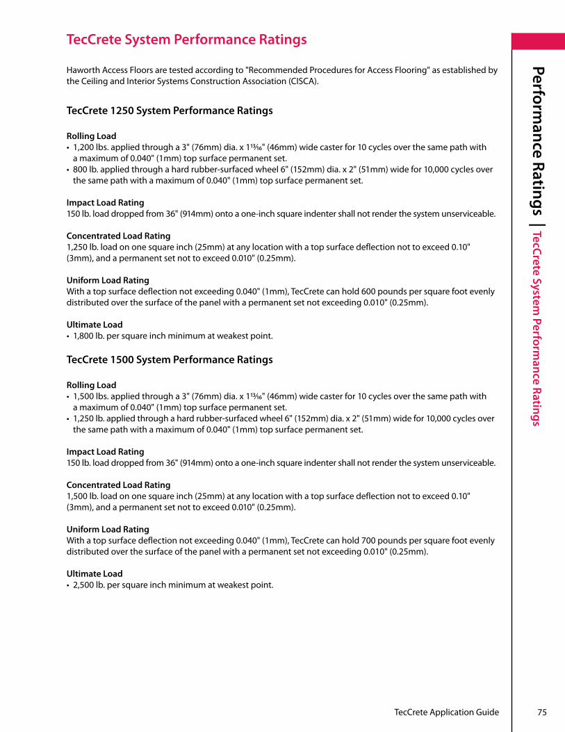
TecCrete System Performance Ratings
HaworthAccessFloorsaretestedaccordingto"RecommendedProceduresforAccessFlooring"asestablishedbytheCeilingandInteriorSystemsConstructionAssociation(CISCA).
TecCrete 1250 System Performance Ratings
Rolling Load • 1,200lbs.appliedthrougha3"(76mm)dia.x113/16"(46mm)widecasterfor10 cycles over the same path with amaximumof0.040"(1mm)topsurfacepermanentset.• 800lb.appliedthroughahardrubber-surfacedwheel6"(152mm)dia.x2"(51mm)widefor10,000 cycles over thesamepathwithamaximumof0.040"(1mm)topsurfacepermanentset.
Impact Load Rating150lb.loaddroppedfrom36"(914mm)ontoaone-inchsquareindentershallnotrenderthesystemunserviceable.
Concentrated Load Rating1,250lb.loadononesquareinch(25mm)atanylocationwithatopsurfacedeflectionnottoexceed0.10"(3mm),andapermanentsetnottoexceed0.010"(0.25mm).
Uniform Load RatingWithatopsurfacedeflectionnotexceeding0.040"(1mm),TecCretecanhold600poundspersquarefootevenlydistributedoverthesurfaceofthepanelwithapermanentsetnotexceeding0.010"(0.25mm).
Ultimate Load• 1,800 lb . per square inch minimum at weakest point .
TecCrete 1500 System Performance Ratings
Rolling Load • 1,500lbs.appliedthrougha3"(76mm)dia.x113/16"(46mm)widecasterfor10 cycles over the same path with amaximumof0.040"(1mm)topsurfacepermanentset.• 1,250lb.appliedthroughahardrubber-surfacedwheel6"(152mm)dia.x2"(51mm)widefor10,000 cycles over thesamepathwithamaximumof0.040"(1mm)topsurfacepermanentset.
Impact Load Rating150lb.loaddroppedfrom36"(914mm)ontoaone-inchsquareindentershallnotrenderthesystemunserviceable.
Concentrated Load Rating1,500lb.loadononesquareinch(25mm)atanylocationwithatopsurfacedeflectionnottoexceed0.10"(3mm),andapermanentsetnottoexceed0.010"(0.25mm).
Uniform Load RatingWithatopsurfacedeflectionnotexceeding0.040"(1mm),TecCretecanhold700poundspersquarefootevenlydistributedoverthesurfaceofthepanelwithapermanentsetnotexceeding0.010"(0.25mm).
Ultimate Load• 2,500lb.persquareinchminimumatweakestpoint.

76 TecCrete Application Guide
Performance Ratings | TecCrete System
Performance Ratings
TecCrete System Performance Ratings
TecCrete 2000/2500 System Performance Ratings
Rolling Load• 2,000lbs.appliedthrougha3"(76mm)dia.x113/16"(46mm)widecasterfor10 cycles over the same path with a maximumof0.040"(1mm)topsurfacepermanentsetwithedgesupportedstringers.• 1,750 lb . applied through a hard rubber-surfaced wheel 10"(254mm)dia.x4"(102mm)widefor10,000 cycles overthesamepathwithamaximumof0.040"(1mm)topsurfacepermanentsetwithedgesupportstringers.
Impact LoadA 150lb.loaddroppedfrom36"(914mm)ontoaone-inch square indenter shall not render the system unserviceable .
Concentrated Load RatingAllows for maximum 2,500 lbs . at 0 .10"deflectionand0.015"permanentset.
Uniform LoadWithatopsurfacedeflectionnotexceeding0.040"(1mm),TecCretecanhold1100poundspersquarefootevenlydistributedoverthesurfaceofthepanelwithapermanentsetnotexceeding0.010"(0.25mm).
Ultimate Load• 3,100lb.persquareinchminimumatweakestpointwithedgesupportstringers.

TecCrete Application Guide 77
This page intentionally left blank .

78 TecCrete Application Guide
This page intentionally left blank .

Three Part Guide Specification
TecCrete Access Flooring: Office
TecCrete®

TecCrete Access Floor System
: Office | Section 09 69 00
80 TecCrete Access Floor System: Office Section 09 69 00
PART 1 - GENERAL
An editable MicroSoft® Word version of this document is available for download at www .haworth .com .
1 .01 Description
A . The access floor system shall consist of interchangeable panels, understructure, and all labor, material,equipment,andinstallationascalledforinthespecificationsand/orshownonthe Architect's Drawings .
B . Access floor manufacturer shall be ISO9001:2000 certified demonstrating it has a robust and well documented quality management system with continual improvement goals and strategies .
C . Access floor manufacturer's facilities shall be ISO14001:2004 certified demonstrating that they maintain an environmental management system .
D . Access floor product must be indoor air quality certified to conform to CA Section 01350 Specification for classroom and standard office .
E. Accessfloorproductshallbemanufacturedinazerolandfillfacility.
F . Related Work Specified Elsewhere:
1 . Concrete work and concrete floor sealer is specified in Section 03 30 00 . a)Concretesealerandpedestaladhesivemustbechemicallycompatiblewitheachother.
2. CarpetandcarpettileworkasspecifiedinSection096800(09680MasterFormat95).
3. MechanicalairdistributionasspecifiedinSection233000(15800MasterFormat95).
4. ElectricalconnectionsandgroundingasspecifiedinSection260500(16100 MasterFormat95).
G . Access Floor Air Plenum Requirements
1 . The access floor contractor is aware that the space beneath the access floor will be used as an air delivery plenum and as such will take the necessary precautions when installing their work so as not to impact the integrity of the plenum space specific to air leakage and cleanliness .
2 . Panel construction shall have a flat steel bottom to create a fully sealed plenum .
3 . When panels are to be used bare without carpet or other floor coverings an optional air sealing gasket may be used to prevent air leakage .
1 .02 Environmental Conditions for Storage and Installation
A . The General Contractor must provide a dry accessible area to receive and unload material with a freepathtoelevators,hoists,and/ortheareareceivingtheaccessfloor.
B . Prior to and during installation, a secure and dry storage space closed to the weather must be made available for the access floor materials, with recommended environment at 40° F to 120° F and approximately 35% to 70% relative humidity, 24 hours a day during and after installation .
C . The subfloor surface must be free of moisture, dust, dirt and other debris . Once installed, the access floor must be maintained in the same manner .

TecCrete Access Floor System
: Office | Section 09 69 00
TecCrete Access Floor System: Office Section 09 69 00 81
1 .03 Design Performance and Certification of Product
A . Provide access flooring system consisting of moveable assemblies composed of modular floor panels supported on pedestals with stringers forming accessible underfloor cavities to accommodateelectrical,mechanical,andHVACservicesandcomplyingwithperformance requirements specified . Raised floor panels must be interchangeable with each other except where cut for special conditions .
B. Whereapplicableloadtestingshallbeperformedaccordingto"RecommendedTestProcedures forAccessFlooring"asestablishedbytheCeilingandInteriorSystemsConstructionAssociation (CISCA).Theseproceduresshallbeusedasaguidelinewhenpresentingloadperformance product information .
The following applies to TecCrete 1250 Raised Access Flooring only:
1. ConcentratedLoad:1,250lb.ononesquareinch(25mm)atanylocationwithatopsurfacedeflection nottoexceed0.10"(2.5mm),andapermanentsetnottoexceed0.010"(0.25mm).
2. UniformLoad:Withatopsurfacedeflectionnotexceeding0.040"(1mm),TecCretecanhold600pounds per square foot evenly distributed over the surface of the panel with a permanent set not exceeding 0.010"(0.25mm).
3 . Ultimate Load: 1,800 lb . per square inch minimum at weakest point .
4. RollingLoad:Panelsshallwithstandarollingloadof1,200lbs.appliedthrougha3"(76mm)dia.x113/16" (46mm)widecasterfor10cyclesoverthesamepathwithamaximumof0.040"(1mm)topsurface permanent set . Panels shall withstand a rolling load of 800 lb . applied through a hard rubber-surfaced wheel6"(152mm)dia.x2"(51mm)widefor10,000cyclesoverthesamepathwithamaximumof0.040" (1mm)topsurfacepermanentset.
5. ImpactLoad:A150lb.loaddroppedfrom36"(914mm)ontoaone-inchsquareindentershallnot render the system unserviceable .
6 . Flammability: Bare panel system shall meet Class A requirements for Flame spread and smoke development when tested in accordance with ASTM-E84 and a maximum Flame spread of 25, Smoke developmentof50basedontheaverageofthreerunswhentestedinaccordancewithCAN/ULCS102.
7 . Combustibility: All components of the access floor system shall qualify as noncombustible by demonstrating compliance with requirements of ASTM E 136, Standard Test Method for Behavior of MaterialsinaVerticalTubeFurnaceat750˚C.
8 . Recycled Content: Panel and understructure system shall be required to have a minimum recycled content of 50% .
The following applies to TecCrete 1500 Raised Access Flooring only:
1.ConcentratedLoad:1,500lbononesquareinch(25mm)loadatanylocationwithatopsurface deflectionnottoexceed0.10"(2.5mm)andapermanentsetnottoexceed0.010"(0.25mm).
2. UniformLoad:Withatopsurfacedeflectionnotexceeding0.040"(1mm),TecCretecanhold700pounds per square foot evenly distributed over the surface of the panel with a permanent set not exceeding 0.010"(0.25mm).
3 . Ultimate Load: Panel shall be designed to withstand load of 2,500 lb . minimum at weakest point with stringer .
PART 1 - GENERAL
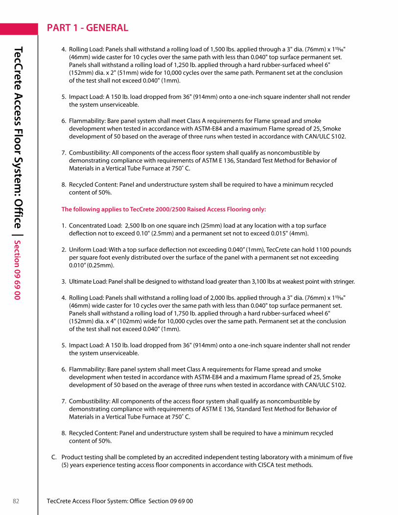
TecCrete Access Floor System
: Office | Section 09 69 00
82 TecCrete Access Floor System: Office Section 09 69 00
PART 1 - GENERAL
4. RollingLoad:Panelsshallwithstandarollingloadof1,500lbs.appliedthrougha3"dia.(76mm)x113/16" (46mm)widecasterfor10cyclesoverthesamepathwithlessthan0.040"topsurfacepermanentset. Panelsshallwithstandarollingloadof1,250lb.appliedthroughahardrubber-surfacedwheel6" (152mm)dia.x2"(51mm)widefor10,000cyclesoverthesamepath.Permanentsetattheconclusion ofthetestshallnotexceed0.040"(1mm).
5. ImpactLoad:A150lb.loaddroppedfrom36"(914mm)ontoaone-inchsquareindentershallnotrender the system unserviceable .
6 . Flammability: Bare panel system shall meet Class A requirements for Flame spread and smoke development when tested in accordance with ASTM-E84 and a maximum Flame spread of 25, Smoke developmentof50basedontheaverageofthreerunswhentestedinaccordancewithCAN/ULCS102.
7 . Combustibility: All components of the access floor system shall qualify as noncombustible by demonstrating compliance with requirements of ASTM E 136, Standard Test Method for Behavior of MaterialsinaVerticalTubeFurnaceat750˚C.
8 . Recycled Content: Panel and understructure system shall be required to have a minimum recycled content of 50% .
The following applies to TecCrete 2000/2500 Raised Access Flooring only:
1. ConcentratedLoad:2,500lbononesquareinch(25mm)loadatanylocationwithatopsurface deflectionnottoexceed0.10"(2.5mm)andapermanentsetnottoexceed0.015"(4mm).
2. UniformLoad:Withatopsurfacedeflectionnotexceeding0.040”(1mm),TecCretecanhold1100pounds per square foot evenly distributed over the surface of the panel with a permanent set not exceeding 0.010”(0.25mm).
3 . Ultimate Load: Panel shall be designed to withstand load greater than 3,100 lbs at weakest point with stringer .
4. RollingLoad:Panelsshallwithstandarollingloadof2,000lbs.appliedthrougha3"dia.(76mm)x113/16" (46mm)widecasterfor10cyclesoverthesamepathwithlessthan0.040"topsurfacepermanentset. Panelsshallwithstandarollingloadof1,750lb.appliedthroughahardrubber-surfacedwheel6" (152mm)dia.x4"(102mm)widefor10,000cyclesoverthesamepath.Permanentsetattheconclusion ofthetestshallnotexceed0.040"(1mm).
5. ImpactLoad:A150lb.loaddroppedfrom36"(914mm)ontoaone-inchsquareindentershallnotrender the system unserviceable .
6 . Flammability: Bare panel system shall meet Class A requirements for Flame spread and smoke development when tested in accordance with ASTM-E84 and a maximum Flame spread of 25, Smoke developmentof50basedontheaverageofthreerunswhentestedinaccordancewithCAN/ULCS102.
7 . Combustibility: All components of the access floor system shall qualify as noncombustible by demonstrating compliance with requirements of ASTM E 136, Standard Test Method for Behavior of MaterialsinaVerticalTubeFurnaceat750˚C.
8 . Recycled Content: Panel and understructure system shall be required to have a minimum recycled content of 50% .
C . Product testing shall be completed by an accredited independent testing laboratory with a minimum of five (5)yearsexperiencetestingaccessfloorcomponentsinaccordancewithCISCAtestmethods.

TecCrete Access Floor System
: Office | Section 09 69 00
TecCrete Access Floor System: Office Section 09 69 00 83
PART 1 - GENERAL
1 .04 Country of Origin
A. AccessfloormaterialsshallcomplywiththeprovisionsoutlinedinFARSubpart25.2–BuyAmerican Act–ConstructionMaterials.
1 .05 Submittals
A . Samples: Submit a sample of the floor panel and each understructure component .
B . Shop Drawings:
1 . Submit drawings showing raised floor panel layout including starting point of installation .
2 . Include details of components panels, and pedestals . If required show edge details of ramps, steps, handrails, and anchoring of pedestal bases to subfloor .
C . Certificates:
1. Submitindependenttestingorganizationcertificatesindicatingcompliancewithspecifieddesigncriteria whentestedandreportedaccordingtoCISCA"RecommendedTestProceduresforAccessFloors."
2 . Submit seismic calculations if required in accordance with local and state building codes as specified . Calculations shall be performed using current seismic program and submitted to a local structural engineerlicensedinthestatewheretheprojectislocated.Thestructuralengineershallsignand seal these calculations confirming that these calculations meet all local and state codes for seismic pedestal assemblies . A signed copy of these calculations must be given to the architect and local building department as required .
1 .06 Quality Assurance
A . Installer: A company with minimum of five years experience in the installation of access floor systems of comparablesizeandcomplexity.
B . Tolerances:
1 . Manufacturing tolerance: a) Nominalpanelsize±0.015"(0.4mm)orless. b) Panelflatness±0.020"(.5mm)orless. c) Panelsquareness±0.015"(0.4mm)orless. d) Panelinterchangeability—allpanels,exceptthosemodifiedtomeetspecialconditions,shall be interchangeable .
2 . Installation Tolerance: a) Finishedinstallationshallbelevelwithin±0.060"(2mm)in10feet(3m)and±0.100"(3mm)for the entire floor .
1.07 ProjectConditions
A. TheGeneralContractorand/orOwnershallprovideaclean,level,drysubfloor,temperaturecontrolled,and protected from the weather .
B . Access flooring storage and installation areas shall be maintained at a temperature between 40° F and 120° F, and between 35% to 70% relative humidity for 24 hours a day before, during and after installation .
C . Overhead construction work must be completed before installing access floor to avoid damage to panels and finishes . Any damage to panels or finishes resulting from construction work done after floor is installed shall be the responsibility of the general contractor or others .

TecCrete Access Floor System
: Office | Section 09 69 00
84 TecCrete Access Floor System: Office Section 09 69 00
PART 2 - PRODUCTS
2 .01 Materials
A . Manufacturer: The access flooring system shall be as manufactured by Haworth Inc . located in Grand Rapids, Michigan 49512 .
1 . Substitutions will be considered, providing the alternative products meet or exceed the feature requirements as indicated herein and the performance requirements including the rolling load as outlined in section 1 .06 and receive prior written approval by the Architect . The manufacturer shall certify that all panels meet or exceed the stated design criteria .
B. FloorPanels:TecCrete1250/1500or2000/2500Panelsshallbeintegratedsteelpanconstructionwith exposed top surface of lightweight concrete fill . Floor Panels are bare cornerlock .
1. Panelsshallbenominal24"(610mm)squarex11/8"(29mm)or1½"(38mm)deep,manufacturedwith galvannealed steel pan having shear tabs that integrally bond to the lightweight, high-strength concrete fill . Panel corners shall be manufactured to receive the pedestal head positioning dome and containing a cornerlock/groundinginsert.Eachpanelshallacceptaflush-fitmetalfastenerwhichsecurelyfastens each panel corner to the pedestal head .
2 . Panel Finish: Floor panel surface shall be factory standard bare concrete for field installed carpet tile . Panels shall have a maximum electrical resistance of 10 ohms or less from the top edge of the panel, less surface covering, to the understructure .
C . Air Supply Panels:
1. Provideand/orinstallpassivefloordiffusersandfactorycutoutsasindicatedondrawings.
2. Factorycutoutsshallbe(centered)(quadrant)asshown.Panelswithcutoutsthatarelocatedin traffic areas as shown on the drawings shall have extra pedestal assemblies under the panel to support the cutout .
3 . For underfloor air applications, provide air strip gaskets for exposed concrete panels, or high-pressure air highways, as indicated .
D . Understructure:
1. Pedestalassembliesshallbeofhot-dipgalvanizedsteel.
2. Thebaseshallbeaminimumof16squareinchesandshallbestampedand/orembossedonits underside and shall be adhered to the subfloor with an adhesive recommended by the access flooring manufacturer .
3. Wheremechanicalanchorsarerequiredforseismiczones,providesameasrequiredbyproject specific seismic calculations .
4 . The threaded stud will be 3/4"(19mm)diametersteel.
5 . The head assembly shall be designed so that the panels will be held in place with or without cornerlock fasteners .
6. Pedestalassemblyshallprovideanadjustmentrangeof+/-1"(25mm)whenfinishedfloorheightis 6"(152mm)ormore,adjustableat1/64"(0.4mm)increments.
7. Theassemblyshallprovideamechanicalmeanstolockthefloorinalevelplaneandadjustments

TecCrete Access Floor System
: Office | Section 09 69 00
TecCrete Access Floor System: Office Section 09 69 00 85
PART 2 - PRODUCTS
shall be capable of being made without special tools .
8 . For cornerlock system, the head of the all-steel assembly shall be designed to accept a metal fastener to mechanically lock the panels in place .
9 . Pedestal assembly shall support not less than 6,000 lb . axial load and shall resist an average 1,000 inch-pound overturning moment when bonded to a clean concrete slab .
E . Stringers:
1 . Stringer shall capture panels and be capable of supporting a 450 lb . concentrated load at mid span with lessthan0.010"permanentsetaftertheloadisremoved.
2 . Stringers shall be individually and rigidly fastened to the pedestal with one machine screw for each foot of stringer length . Bolts shall provide positive electrical contact between the stringers and pedestals . Connections depending on gravity or spring action are unacceptable .
3 . Stringer shall be either 2' x 2' or 4' x 4' pattern and shall be secured by a fastener .
F . Accessories:
1 . Furnish ramps, steps, lateral bracing, fascia, handrails, cutouts, and miscellaneous items where indicated .
2 . Manufacturer of the access floor shall also provide a modular power system, including in-floor service outlets for power, communications, and data wiring in locations as shown on Drawings . a . Zone Distribution Box: Used as transition point to convert from bulk power distribution into easily reconfigurablemodularpowerdistributioncomponents.Supports"plug-and-play"powerdistribution withineachpowerzone. i. 3-PortDistributionboxisconstructedof0.0575"–0.0635"(16gauge)thickblackzincplatedsteelbox with cover . Provided with one 11/4"conduitcontaining21-10AWGwiresinlengthsupto125feet. This is intended to be connected to the building Circuit Breaker box . Three modular ports are factory wired,readyformodularjumpers.Availablein8wire3-or4-Circuitwiringconfiguration. ii. 2-PortDistributionboxisconstructedof0.0575"–0.0635"(16gauge)thickblackzincplatedsteelbox with cover . Provided with one 11/4"conduitcontaining14-8AWGwiresinlengthsof150to200feet. This is intended to be connected to the building Circuit Breaker box . Two modular ports are factory wired,readyformodularjumpers.Availablein8wire3-or4-circuitwiringconfiguration. iii.FieldWiredDistributionboxisconstructedof0.0575"–0.0635"(16gauge)thickblackzincplated steel box with cover . This is intended to be connected to the building Circuit Breaker box by a licensed electrician using 11/4"conduitandappropriatelysizedwire.Terminalstripsinsidethebox areconnectedtothreemodularports,whicharefactorywired,readyformodularjumpers.Available in 8 wire 3- or 4-Circuit wiring configuration . iv.LowProfileDistributionboxisconstructedof0.0575"–0.0635"(16gauge)thickblackzincplated steel box with cover . This is intended to be connected to the building Circuit Breaker box by a licensed electrician using ½"conduitandappropriatelysizedwire.Wireleadsinsidetheboxare connectedtoamodularport,readyforamodularjumper.Availablein8wire3-or4-Circuit wiring configuration .
b. Jumpers:Usedtointerconnectmodularpowercomponentswithineachpowerzone.Flexibleconduit construction with quick connect modular male power connector heads . Available in 8 wire 3-or 4-Circuit wiring configuration . Connector populated with all 8 wires to support future reconfigurations of the power distribution system . Available in 5', 10' 15' and 20' lengths . Available with either all 10 gaugeor10/12gaugewires,all10gaugeisa¾"ovalflexiblemetalconduitandthe10/12gaugeis5/8" ovalbflexible metal conduit .

TecCrete Access Floor System
: Office | Section 09 69 00
86 TecCrete Access Floor System: Office Section 09 69 00
PART 2 - PRODUCTS
c. Splitters:Actas'splitter'tointerconnectuptofourJumperswithineachpowerzone.Constructedwith 8 tin plated copper busbars within polymeric enclosure with integral latching system . Available in 3- or 4-Circuit configurations . Typically one acts as the inlet and the others are outbound branches .
d. ServiceModules:Usedtoprovidepowerand/ordataoutletsatfloorlevel. i. 2.5"DualFlushServiceModuleconstructedof0.0575–0.0635"(16gauge)thickblackzincplated steelboxwith2integralfemaleconnectors.Receptacle/Dataplatesareconcealedunderhinged lid.Powdercoatpainted(black)lidandtrimringwithhingedcordexitport.Lidacceptscarpet insert . Unit fits in 10½"squareopeninginraisedaccessfloortile.Unitissecuredtofloortileusing four mounting screws . Available in 8 wire 3- or 4-Circuit configurations . Unit accepts two modular receptacles, which are specified separately, with common or isolated ground receptacles . Available in2.5"2-gangconfiguration. ii. 4.5"QuadFlushServiceModuleconstructedof0.0575–0.0635"(16gauge)thickblackzincplated steelboxwith4integralfemaleconnectors.Receptacle/Dataplatesareconcealedunderhinged lid.Powdercoatpainted(black)lidandtrimringwithhingedcordexitport.Lidacceptscarpet insert . Unit fits in 10½"squareopeninginraisedaccessfloortile.Unitissecuredtofloortile using four mounting screws . Available in 8 wire 3- or 4-Circuit configurations . Unit accepts four modular receptacles, which are specified separately, with common or isolated ground receptacles . Availablein4.5"4-gangconfiguration.
e. SystemsFurnitureFeed:Usedtoconnectsystemsfurnituremodularwiringdirectlytozone power distribution . i . Haworth Base Feeds are constructed with male connector head for quick connect attachment to Jumpersofzonepowersystem.Availablein3-or4-Circuitconfiguration,dependingontypeof poweravailableintheHaworthFurniture.BasefeedsareUL/CSAlistedfordirectconnectionto the Jumpers .

TecCrete Access Floor System
: Office | Section 09 69 00
TecCrete Access Floor System: Office Section 09 69 00 87
PART 3 - EXECUTION
3 .01 Inspection
A . Examine the subfloor which is to receive access flooring for dryness, cleanliness, unevenness, or any irregularities that will affect the quality of the access flooring .
1. Verifythatmaterialstorageandinstallationareasareatrecommendedtemperatureand relative humidity before, during, and after installation .
2. Verifythatsubstrateisleveltowithin1/8"(3mm)in10'(3m).
3 . Do not commence installation of access flooring until subfloor is clean and dry, temperature controlled, and protected from the weather .
3 .02 Installation
A . Pedestal locations shall be established from approved shop drawings so that mechanical and electrical work can be installed without interfering with pedestal locations .
B . Installer is to coordinate with other trades to maintain the integrity of the installed access flooring . All traffic on access floor shall be controlled by the installer only . No traffic other than the access floor installation crew shall be permitted on any floor area for 48 hours to allow the pedestal adhesive to set . Access floor panels shall not be removed by other trades for 72 hours after their installation .
C. Floorsystemandaccessoriesshallbeinstalledbyanauthorizedfactory-trainedinstallation companywithaminimumoffive(5)yearsexperience.
D . No dust or debris producing operations by other trades shall be allowed in areas where access floor is being installed to ensure proper bonding of pedestals to subfloor .
E . Installer shall keep the subfloor broom clean as installation progresses .
F . Install floor diffusers if required as indicated on Mechanical Plans .
G. Finishedinstallationshallbelevelwithin+/-0.060"(2mm)in10'(3m)and+/-0.100"(3mm)forthe entire floor area .
H . Replace damaged materials prior to the application of field applied surfaces .
I . The General Contractor or Subcontractor shall assure compatibility between the concrete sealer and the pedestal adhesive provided by the access floor manufacturer.
3 .03 Acceptance
A . General Contractor or Owner shall accept completed access floor in whole or in part, prior to allowing other trades to perform work which affects the installed access floor .
B . General Contractor shall suitably protect the accepted access floor and accessories from damage, contamination, or overloading .
C . The General Contractor shall be responsible for the final underfloor cleaning .

88 TecCrete Access Floor System: Office Section 09 69 00
This page intentionally left blank .

Three Part Guide Specification
TecCrete Access Flooring: Computer Rooms
TecCrete®
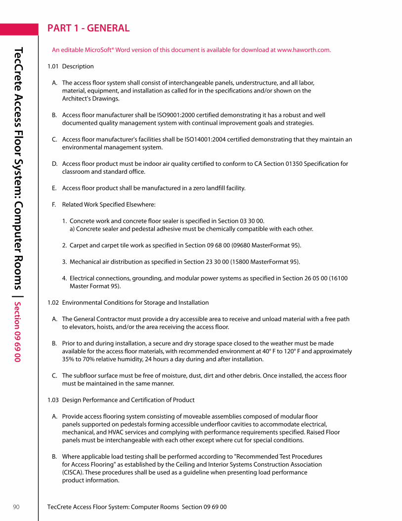
TecCrete Access Floor System
: Computer Room
s | Section 09 69 00
90 TecCrete Access Floor System: Computer Rooms Section 09 69 00
PART 1 - GENERAL
An editable MicroSoft® Word version of this document is available for download at www .haworth .com .
1 .01 Description
A . The access floor system shall consist of interchangeable panels, understructure, and all labor, material,equipment,andinstallationascalledforinthespecificationsand/orshownonthe Architect's Drawings .
B . Access floor manufacturer shall be ISO9001:2000 certified demonstrating it has a robust and well documented quality management system with continual improvement goals and strategies .
C . Access floor manufacturer's facilities shall be ISO14001:2004 certified demonstrating that they maintain an environmental management system .
D . Access floor product must be indoor air quality certified to conform to CA Section 01350 Specification for classroom and standard office .
E. Accessfloorproductshallbemanufacturedinazerolandfillfacility.
F . Related Work Specified Elsewhere:
1 . Concrete work and concrete floor sealer is specified in Section 03 30 00 . a)Concretesealerandpedestaladhesivemustbechemicallycompatiblewitheachother.
2. CarpetandcarpettileworkasspecifiedinSection096800(09680MasterFormat95).
3. MechanicalairdistributionasspecifiedinSection233000(15800MasterFormat95).
4. Electricalconnections,grounding,andmodularpowersystemsasspecifiedinSection260500(16100 MasterFormat95).
1 .02 Environmental Conditions for Storage and Installation
A . The General Contractor must provide a dry accessible area to receive and unload material with a free path toelevators,hoists,and/ortheareareceivingtheaccessfloor.
B . Prior to and during installation, a secure and dry storage space closed to the weather must be made available for the access floor materials, with recommended environment at 40° F to 120° F and approximately 35% to 70% relative humidity, 24 hours a day during and after installation .
C . The subfloor surface must be free of moisture, dust, dirt and other debris . Once installed, the access floor must be maintained in the same manner .
1 .03 Design Performance and Certification of Product
A . Provide access flooring system consisting of moveable assemblies composed of modular floor panels supported on pedestals forming accessible underfloor cavities to accommodate electrical, mechanical,andHVACservicesandcomplyingwithperformancerequirementsspecified.RaisedFloor panels must be interchangeable with each other except where cut for special conditions .
B. Whereapplicableloadtestingshallbeperformedaccordingto"RecommendedTestProcedures forAccessFlooring"asestablishedbytheCeilingandInteriorSystemsConstructionAssociation (CISCA).Theseproceduresshallbeusedasaguidelinewhenpresentingloadperformance product information .

TecCrete Access Floor System
: Computer Room
s | Section 09 69 00
TecCrete Access Floor System: Computer Rooms Section 09 69 00 91
PART 1 - GENERAL
The following applies to TecCrete 1250 Raised Access Flooring only:
1. ConcentratedLoad:1,250lb.ononesquareinch(25mm)atanylocationwithatopsurfacedeflection nottoexceed0.10"(2.5mm),andapermanentsetnottoexceed0.010"(0.25mm).
2. UniformLoad:Withatopsurfacedeflectionnotexceeding0.040"(1mm),TecCretecanhold600pounds per square foot evenly distributed over the surface of the panel with a permanent set not exceeding 0.010"(0.25mm).
3 . Ultimate Load: 1,800 lb . per square inch minimum at weakest point .
4. RollingLoad:Panelsshallwithstandarollingloadof1,200lbs.appliedthrougha3"(76mm)dia.x 113/16"(46mm)widecasterfor10cyclesoverthesamepathwithamaximumof0.040"(1mm)topsurface permanent set . Panels shall withstand a rolling load of 800 lb . applied through a hard rubber-surfaced wheel6"(152mm)dia.x2"(51mm)widefor10,000cyclesoverthesamepathwithamaximumof0.040" (1mm)topsurfacepermanentset.
5. ImpactLoad:A150lb.loaddroppedfrom36"(914mm)ontoaone-inchsquareindentershallnotrender the system unserviceable .
6 . Flammability: Bare panel system shall meet Class A requirements for Flame spread and smoke development when tested in accordance with ASTM-E84 and a maximum Flame spread of 25, Smoke developmentof50basedontheaverageofthreerunswhentestedinaccordancewithCAN/ULCS102.
7 . Combustibility: All components of the access floor system shall qualify as noncombustible by demonstrating compliance with requirements of ASTM E 136, Standard Test Method for Behavior of MaterialsinaVerticalTubeFurnaceat750˚C.
8 . Recycled Content: Panel and understructure system shall be required to have a minimum recycled content of 50% .
The following applies to TecCrete 1500 Raised Access Flooring only:
1. ConcentratedLoad:1,500lbononesquareinch(25mm)loadatanylocationwithatopsurface deflectionnottoexceed0.10"(2.5mm)andapermanentsetnottoexceed0.010"(0.25mm).
2. UniformLoad:700lb.persquarefootwithamaximumtopsurfacedeflectionnottoexceed0.040" (1mm),andapermanentsetnottoexceed0.010"(0.25mm).
3. UltimateLoad:Withatopsurfacedeflectionnotexceeding0.040"(1mm),TecCretecanhold700pounds per square foot evenly distributed over the surface of the panel with a permanent set not exceeding 0.010"(0.25mm).
4. RollingLoad:Panelsshallwithstandarollingloadof1,500lbs.appliedthrougha3"dia.(76mm)x113/16" (46mm)widecasterfor10cyclesoverthesamepathwithlessthan0.040"topsurfacepermanentset. Panels shall withstand a rolling load of 1,250 lb . applied through a hard rubber-surfaced wheel 6"(152mm)dia.x2"(51mm)widefor10,000cyclesoverthesamepath.Permanentsetattheconclusion ofthetestshallnotexceed0.040"(1mm).
5. ImpactLoad:A150lb.loaddroppedfrom36"(914mm)ontoaone-inchsquareindentershallnotrender the system unserviceable .

TecCrete Access Floor System
: Computer Room
s | Section 09 69 00
92 TecCrete Access Floor System: Computer Rooms Section 09 69 00
PART 1 - GENERAL
6 . Flammability: Bare panel system shall meet Class A requirements for Flame spread and smoke development when tested in accordance with ASTM-E84 and a maximum Flame spread of 25, Smoke developmentof50basedontheaverageofthreerunswhentestedinaccordancewithCAN/ULCS102.
7 . Combustibility: All components of the access floor system shall qualify as noncombustible by demonstrating compliance with requirements of ASTM E 136, Standard Test Method for Behavior of MaterialsinaVerticalTubeFurnaceat750˚C.
8 . Recycled Content: Panel and understructure system shall be required to have a minimum recycled content of 50% .
The following applies to TecCrete 2000/2500 Raised Access Flooring only:
1. ConcentratedLoad:2,500lbononesquareinch(25mm)loadatanylocationwithatopsurface deflectionnottoexceed0.10”(2.5mm)andapermanentsetnottoexceed0.015”(4mm).
2. UniformLoad:Withatopsurfacedeflectionnotexceeding0.040”(1mm),TecCretecanhold1100pounds per square foot evenly distributed over the surface of the panel with a permanent set not exceeding 0.010”(0.25mm).
3 . Ultimate Load: Panel shall be designed to withstand load greater than 3,100 lbs at weakest point with stringer .
4. RollingLoad:Panelsshallwithstandarollingloadof2,000lbs.appliedthrougha3”dia.(76mm)x 113/16”(46mm)widecasterfor10cyclesoverthesamepathwithlessthan0.040”topsurfacepermanent set . Panels shall withstand a rolling load of 1,750 lb . applied through a hard rubber-surfaced wheel 6”(152mm)dia.x4”(102mm)widefor10,000cyclesoverthesamepath.Permanentsetattheconclusion ofthetestshallnotexceed0.040”(1mm).
5. ImpactLoad:A150lb.loaddroppedfrom36”(914mm)ontoaone-inchsquareindentershallnotrender the system unserviceable .
6 . Flammability: Bare panel system shall meet Class A requirements for Flame spread and smoke development when tested in accordance with ASTM-E84 and a maximum Flame spread of 25, Smoke developmentof50basedontheaverageofthreerunswhentestedinaccordancewithCAN/ULCS102.
7 . Combustibility: All components of the access floor system shall qualify as noncombustible by demonstrating compliance with requirements of ASTM E 136, Standard Test Method for Behavior of MaterialsinaVerticalTubeFurnaceat750˚C.
8 . Recycled Content: Panel and understructure system shall be required to have a minimum recycled content of 50% .
C . Product testing shall be completed by an accredited independent testing laboratory . with a minimum of five(5)yearsexperiencetestingaccessfloorcomponentsinaccordancewithCISCAtestmethods.
1 .04 Country of Origin
A. AccessfloormaterialsshallcomplywiththeprovisionsoutlinedinFARSubpart25.2–BuyAmerican Act–ConstructionMaterials.
1 .05 Submittals

TecCrete Access Floor System
: Computer Room
s | Section 09 69 00
TecCrete Access Floor System: Computer Rooms Section 09 69 00 93
PART 1 - GENERAL
A . Samples: Submit a sample of the floor panel and each understructure component .
B . Shop Drawings:
1 . Submit drawings showing raised floor panel layout including starting point of installation .
2 . Include details of floor panel layout including ramps, steps, handrails and anchoring of pedestal bases to subfloor and panel edge details .
C . Certificates:
1. Submitindependenttestingorganizationcertificatesindicatingcompliancewithspecifieddesign criteriawhentestedandreportedaccordingtoCISCA"RecommendedTestProceduresforAccessFloors."
2 . Submit seismic calculations if required in accordance with local and state building codes as specified . Calculations shall be performed using current seismic program and submitted to a local structural engineerlicensedinthestatewheretheprojectislocated.Thestructuralengineershallsignand seal these calculations confirming that these calculations meet all local and state codes for seismic pedestal assemblies . A signed copy of these calculations must be given to the architect and local building department as required .
1 .06 Quality Assurance
A . Installer: A company with minimum of five years experience in the installation of access floor systemsofcomparablesizeandcomplexity.
B . Tolerances:
1 . Manufacturing tolerance: a) Nominalpanelsize±0.015"(0.4mm)orless. b) Panelflatness±0.020"(0.5mm)orless. c) Panelsquareness±0.015"(0.4mm)orless. d) Panelinterchangeability—allpanels,exceptthosemodifiedtomeetspecialconditions, shall be interchangeable .
2 . Installation Tolerance: a) Finishedinstallationshallbelevelwithin±0.060"(2mm)in10feet(3m)and±0.100"(3mm) for the entire floor .
1.07 ProjectConditions
A. TheGeneralContractorand/orOwnershallprovideaclean,level,drysubfloor,temperaturecontrolled, and protected from the weather .
B . Access flooring storage and installation areas shall be maintained at a temperature between 40° F and 120° F, and between 35% to 70% relative humidity for 24 hours a day before, during and after installation .
C . Overhead construction work must be completed before installing access floor to avoid damage to panels and finishes . Any damage to panels or finishes resulting from construction work done after floor is installed shall be the responsibility of the General Contractor or others .

TecCrete Access Floor System
: Computer Room
s | Section 09 69 00
94 TecCrete Access Floor System: Computer Rooms Section 09 69 00
PART 2 - PRODUCTS
2 .01 Materials
A . Manufacturer: The access flooring system shall be as manufactured by Haworth Inc . located in Grand Rapids, Michigan 49512 .
1 . Substitutions will be considered, providing the alternative products meet or exceed the feature requirements as indicated herein and the performance requirements including the rolling load as outlined in section 1 .03 and receive prior written approval by the Architect . The manufacturer shall certify that all panels meet or exceed the stated design criteria .
B. FloorPanels:TecCrete1250/1500or2000/2500Panelsshallbeintegratedsteelpanconstructionwithexposed top surface of lightweight concrete fill covered with a factory applied finish .
1. Panelsshallbenominal24"(610mm)squarex11/8"(29mm)deepor1½"(38mm)deep,manufactured with galvannealed steel pan having shear tabs that integrally bond to the lightweight, high- strength concrete fill . Panel corners shall be manufactured to receive the pedestal head positioning domeandcontainingacornerlock/groundinginsert.Eachpanelshallacceptaflush-fitmetalfastener which securely fastens each panel corner to the pedestal head or stringer .
2 . Panel Finish: Floor panel surface shall be factory applied 1/8"or1/16"thickhigh-pressurelaminate,static dissipative or conductive vinyl as indicated on the Architectural Plans . High-pressure laminates shall be optionally finished with the TecTrim edge . One-piece vinyl tile shall be optionally finished at the edges with vinyl trim, as indicated on the Architectural Plans . Panels shall have a maximum electrical resistance of 10 ohms or less from the top edge of the panel to the understructure, less surface covering, as tested according to NFPA 99 modified .
C . Air Supply Panels:
1. Provideand/orinstallpassivefloordiffusersandfactorycutoutsasindicatedondrawings.
2. Factorycutoutsshallbe(centered)(quadrant)asshown.Panelswithcutoutsthatarelocatedin traffic areas as shown on the drawings shall have extra pedestal assemblies under the panel to support the cutout .
3 . For underfloor air applications, provide air strip gaskets for exposed concrete panels, or high-pressure air highways, as indicated .
D . Understructure:
1. Pedestalassembliesshallbegalvanizedsteel.
2. Thebaseshallbeaminimumof16squareinchesandshallbestampedand/orembossedonits underside and shall be adhered to the subfloor with an adhesive recommended by the access flooring manufacturer .
3. Wheremechanicalanchorsarerequiredforseismiczones,providesameasrequiredbyproject specific seismic calculations .
4 . The threaded stud will be 3/4"(19mm)diametersteel.
5 . The head assembly shall be designed so that the panels will be held in place with or without cornerlock fasteners .

TecCrete Access Floor System
: Computer Room
s | Section 09 69 00
TecCrete Access Floor System: Computer Rooms Section 09 69 00 95
PART 2 - PRODUCTS
6. Pedestalassemblyshallprovideanadjustmentrangeof+/-1"(25mm)whenfinishedfloorheight is6"(152mm)ormore,adjustableat1/64"(0.4mm)incrementswithoutrotatingpedestalhead.
7. Theassemblyshallprovideamechanicalmeanstolockthefloorinalevelplaneandadjustments shall be capable of being made without special tools .
8 . For cornerlock system, the head of the all-steel assembly shall be designed to accept a metal fastener to mechanically lock the panels in place .
9 . Pedestal assembly shall support not less than 6,000 lb . axial load and shall resist an average 1,000 inch-pound overturning moment when bonded to a clean concrete slab .
E . Stringers:
1 . Stringer shall capture panels and be capable of supporting a 450 lb . concentrated load at mid span withlessthan0.010"permanentsetaftertheloadisremoved.
2 . Stringers shall be individually and rigidly fastened to the pedestal with one machine screw for each foot of stringer length . Bolts shall provide positive electrical contact between the stringers and pedestals . Connections depending on gravity or spring action are unacceptable
3 . Stringer shall be either 2' x 2' or 4' x 4' pattern and shall be secured by a fastener .
F . Accessories:
1 . Furnish ramps, steps, lateral bracing, fascia, handrails, cutouts and miscellaneous items where indicated .
2 . Provide modular power system, including in-floor service outlets for power, communications, and data wiring in locations as shown on Drawings .

TecCrete Access Floor System
: Computer Room
s | Section 09 69 00
96 TecCrete Access Floor System: Computer Rooms Section 09 69 00
PART 3 - EXECUTION
3 .01 Inspection
A . Examine the subfloor which is to receive access flooring for dryness, cleanliness, unevenness, or any irregularities that will affect the quality of the access flooring .
1. Verifythatmaterialstorageandinstallationareasareatrecommendedtemperatureandrelative humidity before, during, and after installation .
2. Verifythatsubstrateisleveltowithin1/8"(3mm)in10feet(3m).
B . Do not commence installation of access flooring until subfloor is clean and dry, temperature controlled, and protected from the weather .
3 .02 Installation
A . Pedestal locations shall be established from approved shop drawings so that mechanical and electrical work can be installed without interfering with pedestal locations .
B . Installer is to coordinate with other trades to maintain the integrity of the installed access flooring . All traffic on access floor shall be controlled by the installer only . No traffic other than the access floor installation crew shall be permitted on any floor area for 48 hours to allow the pedestal adhesive to set . Access floor panels shall not be removed by other trades for 72 hours after their installation .
C. Floorsystemandaccessoriesshallbeinstalledbyanauthorizedfactory-trainedinstallationcompanywitha minimumoffive(5)yearsexperience.
D . No dust or debris producing operations by other trades shall be allowed in areas where access floor is being installed to ensure proper bonding of pedestals to subfloor .
E . Installer shall keep the subfloor broom clean as installation progresses .
F . Install floor diffusers if required as indicated on Mechanical Plans .
G. Finishedinstallationshallbelevelwithin+/-0.060"(2mm)in10feet(3m)and+/-0.100"(3mm)forthe entire floor area .
H . Replace damaged materials prior to the application of field applied surfaces .
I . The General Contractor or Subcontractor shall assure compatibility between the concrete sealer and the pedestal adhesive provided by the access floor manufacturer .
3 .03 Acceptance
A . General Contractor or Owner shall accept completed access floor in whole or in part, prior to allowing other trades to perform work which affects the installed access floor .
B . General Contractor shall suitably protect the accepted access floor and accessories from damage, contamination, or overloading .
C . The General Contractor shall be responsible for the final underfloor cleaning .

TecCrete Access Floor System: Computer Rooms Section 09 69 00 97
This page intentionally left blank .

98 TecCrete Access Floor System: Computer Rooms Section 09 69 00
This page intentionally left blank .

Electronic Update(s) for TecCrete Application Guide
Date New Page(s) Revised Page(s) Description
November, 2010 14
Test results for the 1 ½” panel listed on page 14
have changed. Please refer to your tech sheet
for the latest test results.”


Cover is printed on 100% chlorine-free paper. Internal pages are manufactured with 10% post-consumer fiber.
For more information call 800.344.2600 or 616.393.3000.
Haworth is a registered trademark of Haworth, Inc.Printed in USA ©Haworth, Inc. 2009 07.09 Item #1238
haworth.com | haworth-europe.com | haworth-asia.com