Tecal 650H Calibrator Operator's Manual 65… · Tecal 650H Calibrator Operator's Manual. PAGE 1 T...
30
Issue 9. Date of issue: 23rd July 2003 The Techne logo is the trademark of Techne and Techne Inc. © Techne, 2003 Tecal 650H Calibrator Operator's Manual
Transcript of Tecal 650H Calibrator Operator's Manual 65… · Tecal 650H Calibrator Operator's Manual. PAGE 1 T...

Issue 9.Date of issue:23rd July 2003
The Techne logo is the trademark ofTechne and Techne Inc.
© Techne, 2003
Tecal 650HCalibrator
Operator's Manual
r_sanchez
New Stamp


PAGE 1
T E C A L 6 5 0 H O P E R A T O R ’ S M A N U A L
CONTENTS
Hi-Spec Dri-Block® Calibrator Operator’s Manualpage
SAFETY AND INSTALLATIONDeclaration of Conformity 3English 4Français 5Deutsch 6Español 7
THE CALIBRATOR 8Applications 8Warning 9Packing 9Specification 10Working conditions 10
THE FRONT PANEL 11Front panel controls 12When you switch on 15Configure Menu 15
MANUAL MODE 16
PROGRAM MODE 17Run Program 17New Program 18Program Running Display 19Switch Test 20Program Delete 21Cooling Probe 22After use 22
RS232 SERIAL INTERFACE 23To Retrieve Test Results 23To Retrieve a Program 23
TECHNICAL INFORMATION 24General advice 24General Fault finding 24Replacement parts 25Accessories 25Inserts 26
GLOSSARY 27

PAGE 2
T E C A L 6 5 0 H O P E R A T O R ’ S M A N U A L

PAGE 3
T E C A L 6 5 0 H O P E R A T O R ’ S M A N U A L
TechneDuxfordCambridgeCB2 4PZ
Declaration of ConformityTechne Unit Tecal 650H has been designed to comply with the following EuropeanStandards:
EN 50081-1:1992 Electromagnetic Compatibility; Generic emission standard.EN 50082-1:1992 Electromagnetic Compatibility; Generic immunity standard(Performance criterion B).
EN 61010-1:1993 Safety requirements for electrical equipment for measurement, controland laboratory use.
EN 61010-2-010:1995 Particular requirements for laboratory equipment for the heatingof materials.
I have made all reasonable enquiries regarding the unit stated and its conformance tothe following EU directives:Low Voltage directive, 73/23/EEC and amendment 93/68/EEC, andEMC Directive 89/336/EEC and amendments 91/263/EEC 92/31/EEC and 93/68/EEC.
To the best of my knowledge and belief these units conform to these directives.
This Declaration is controlled under an ISO 9001:2000 system certificated by BSI QualityAssurance, certificate number FM13585.
Signature
Name B C Coombes
Position Quality Manager
Issue 4 23/07/2003

PAGE 4
T E C A L 6 5 0 H O P E R A T O R ’ S M A N U A L
GuaranteeThe unit is guaranteed against any defect in material orworkmanship for the period specified on the enclosedguarantee card. This period is from the date of purchase,and within this period all defective parts will be replacedfree of charge provided that the defect is not the result ofmisuse, accident or negligence. Servicing under thisguarantee should be obtained from the supplier.Notwithstanding the description and specification(s) ofthe units contained in the Operator’s Manual, Technehereby reserves the right to make such changes as it seesfit to the units or to any component of the units.This Manual has been prepared solely for the convenienceof Techne customers and nothing in this Instruction Bookshall be taken as a warranty, condition or representationconcerning the description, merchantability, fitness forpurpose or otherwise of the units or components.
User maintenanceNOTE THAT THIS EQUIPMENT SHOULD ONLY BEDISMANTLED BY PROPERLY TRAINED PERSONNEL.REMOVING THE SIDE, FRONT OR REAR PANELS EXPOSESPOTENTIALLY LETHAL MAINS VOLTAGES.THERE ARE NO USER MAINTAINABLE PARTS WITHIN THEEQUIPMENT.In the unlikely event that you experience any problemswith your unit which cannot easily be remedied, youshould contact your supplier and return the unit ifnecessary. Please include any details of the fault observedand remember to return the unit in its original packing.Techne accept no responsibility for damage to units whichare not properly packed for shipping: if in doubt, contactyour supplier. See the Decontamination Certificate suppliedwith your unit.1. Cleaning
Before cleaning your unit ALWAYS disconnect fromthe power supply and allow to cool below 50° C.Your unit can be cleaned by wiping with a damp soapycloth. Care should be exercised to prevent water fromrunning inside the unit. Do not use abrasive cleaners.
2. FusesYour unit is protected by one or two fuses. Theseshould only be changed by suitably qualified personnel.If the fuses blow persistently, a serious fault isindicated and you may need to return the unit to yoursupplier for repair.
Contact InformationFor technical, sales or servicing information, contact yourlocal Techne dealer or,Techne, Duxford,Cambridge, CB2 4PZ, United Kingdom.
Telephone: +44(0)1223 832401Fax: +44(0)1223 836838Service: +44 (0)1223 836950 Out of officehourse-mail: [email protected] site: www.techne.com
or,Techne Inc, 3 Terri Lane,Suite 10, Burlington,New Jersey 08016, USA.
Telephone: 609-589-2560Toll free: 800-225-9243 ext 306Fax: 609-589-2571e-mail: [email protected] site: www.techneusa.com
IntroductionPlease read all the information in this booklet before usingthe unit.
WarningHIGH TEMPERATURES ARE DANGEROUS: they can causeserious burns to operators and ignite combustible material.Techne have taken great care in the design of these unitsto protect operators from hazards, but users should payattention to the following points:• USE CARE AND WEAR PROTECTIVE GLOVES TO
PROTECT HANDS;• DO NOT put hot objects on or near combustible
objects;• DO NOT operate the unit close to inflammable liquids
or gases;• DO NOT place any liquid directly in your unit;• At all times USE COMMON SENSE.
Operator SafetyAll users of Techne equipment must have available therelevant literature needed to ensure their safety.It is important that only suitably trained personnel operatethis equipment, in accordance with the instructionscontained in this manual and with general safety standardsand procedures. If the equipment is used in a manner notspecified by Techne the protection provided by theequipment to the user may be impaired.All Techne units have been designed to conform tointernational safety requirements and are fitted with anovertemperature cutout. On some models, the cutout isadjustable and should be set to suit the application. On allother models the cutout is preset to protect the unit.If a safety problem should be encountered, switch off atthe mains socket and remove the plug from the supply.
Installation1. All Techne units are supplied with a power cable. This
may be integral or plug-in.2. Before connecting the mains supply, check the voltage
against the rating plate. Connect the mains cable to asuitable plug according to the table below. Note thatthe unit must be earthed to ensure properelectrical safety.
Connections 220/240V 110/120VLive Brown BlackNeutral Blue WhiteEarth Green/yellow Green
The fused plug supplied with the mains lead for usein the UK is fitted with the following value fuse toprotect the cable:
230V UK 10 AMPThe fuse in the unit protects the unit and the operator.Note that units marked 230V on the rating plate workat 220V; units marked 120V work at 110V. In bothcases, however, the heating rate will degrade byapproximately 8%. The rating plate is on the rear ofthe unit.
3. Plug the mains cable into the socket on the rear of theunit.
4. Place the unit on a suitable bench or flat workspace,or in a fume cupboard if required, ensuring that the airinlet vents on the underside are free from obstruction.
5. Note that the following symbols may be next to theindicator lamps on the front panel of the units and havethe following meanings:
: the power indicator
: the heater indicator
: the overtemperature indicator
6. Symbols on or near the power switch of the unit havethe following meanings:
I : mains switch OnO : mains switch Off
After useWhen you have finished heating samples, remember thatparts of the unit – the tubes, blocks and associatedaccessories – may be very hot. Take the precautionslisted earlier.

PAGE 5
T E C A L 6 5 0 H O P E R A T O R ’ S M A N U A L
IntroductionVeuillez lire attentivement toutes les instructions de cedocument avant d’utiliser l’appareil.
AvertissementDANGER DE TEMPERATURES ELEVEES : les opérateurspeuvent subir de graves brûlures et les matériauxcombustibles risquent de prendre feu.Techne a apporté un soin tout particulier à la conceptionde ces appareils de façon à assurer une protectionmaximale des opérateurs, mais il est recommandé auxutilisateurs de porter une attention spéciale aux pointssuivants :• PROCEDER AVEC SOIN ET PORTER DES GANTS
POUR SE PROTEGER LES MAINS.• NE PAS poser d’objets chauds sur ou près de matériaux
combustibles.• NE PAS utiliser l’appareil à proximité de liquides ou de
gaz inflammables.• NE PAS verser de liquide directement dans l’appareil.• FAIRE TOUJOURS PREUVE DE BON SENS.
Sécurité de l’opérateurTous les utilisateurs de produits Techne doivent avoir prisconnaissance des manuels et instructions nécessaires àla garantie de leur sécurité.Important : cet appareil doit impérativement être manipulépar un personnel qualifié et utilisé selon les instructionsdonnées dans ce document, en accord avec les normeset procédures de sécurité générales. Dans le cas où cetappareil ne serait pas utilisé selon les consignes préciséespar Techne, la protection pour l’utilisateur ne serait alorsplus garantie.Tous les appareils Techne sont conçus pour répondreaux normes de sécurité internationales et sont dotés d’uncoupe-circuit en cas d’excès de température. Sur certainsmodèles, ce coupe-circuit est réglable pour s’adapter àl’application désirée. Sur d’autres modèles, il est pré-réglée en usine pour assurer la protection de l’appareil.Dans le cas d’un problème de sécurité, coupez l’alimentationélectrique au niveau de la prise murale et enlevez la priseconnectée à l’appareil.
Installation1. Tous les appareils Techne sont livrés avec un câble
d’alimentation qui peut être intégré à l’appareil ou àraccorder.
2. Avant de brancher l’appareil, vérifiez la tension requiseindiquée sur la plaque d’identification. Raccordez lecâble électrique à la prise appropriée en vous reportantau tableau ci-dessous. Il est important quel’appareil soit relié à la terre pour assurer laprotection électrique requise.Connexions 220/240 V 110/120 VPhase Marron NoirNeutre Blue BlancTerre Vert/juane VertLe fusible de la prise fournie avec le câble électriquepour une utilisation au Royaume-Uni est destiné à laprotection du câble: 230 V Royaume-Uni 10 ALe fusible à l’intérieur de l’appareil est destiné àassurer la protection de l’appareil et de l’opérateur.Remarque : les appareils dont la plaque indique 230V peuvent fonctionner sur 220 V, et ceux dont laplaque indique 120 V peuvent fonctionner sur 110 V.Dans les deux cas cependant, le capacité de chauffagediminuera d’environ 8 %. La plaque d’identification setrouve à l’arrière de l’appareil.
3. Raccordez le câble d’alimentation à la prise située àl’arrière de l’appareil.
4. Placez l’appareil sur un plan de travail ou surfaceplane, ou le cas échéant, dans une hotte d’aspiration,en s’assurant que les trous d’aération situés sousl’appareil ne sont pas obstrués.
5. Les symboles ci-dessous situés à côté des témoinslumineux sur la face avant de l’appareil ont lasignification suivante :
: témoin d’alimentation
: témoin de chauffage
: témoin d’excès de température6. Les symboles situés sur ou à côté de l’interrupteur de
l’appareil ont la signification suivante :O : arrêt l : marche
Après utilisationLorsque vous avez fini de chauffer les échantillons,n’oubliez pas que certaines parties de l’appareil - leséprouvettes, leurs supports et autres accessoires -risquent d’être très chaudes. Il est donc recommandé detoujours prendre les précautions citées plus haut.
GarantieL’appareil est garanti contre tout défaut ou vice defabrication pour la durée figurant sur la carte de garantie,à compter de la date d’achat de l’appareil. Au cours decette période, toutes les pièces défectueuses serontremplacées gratuitement, dans la mesure où la défaillancen’est pas due à une mauvaise utilisation, un accident ouune négligence. Toute réparation sous garantie seraeffectuée par le fournisseur.Malgré la description et les spécifications de l’appareildonnées dans le manuel de l’utilisateur, Techne se réservele droit d’effectuer les changements nécessaires àl’appareil ou à tout élément qui entre dans sa composition.Ce manuel a été exclusivement rédigé à l’attention desclients de Techne, et aucun élément de ce guided’instructions ne peut être utilisé comme garantie, conditionou représentation concernant la description,commercialisation, adaptation aux conditions d’utilisationou autre des appareils ou de leurs composants.
Entretien utilisateurIMPORTANT : CET APPAREIL NE PEUT ETRE DEMONTEQUE PAR DU PERSONNEL QUALIFIE.LORSQUE LES PANNEAUX AVANT, ARRIERE ETLATERAUX SONT DEMONTES, L’OPERATEUR ESTEXPOSE A DES TENSIONS QUI PEUVENT ETREMORTELLES.CET APPAREIL NE CONTIENT AUCUN ELEMENT QUIDEMANDE UN ENTRETIEN DE LA PART DE L’UTILISATEUR.Dans le cas peu probable où votre appareil présente undéfaut de fonctionnement auquel il est difficile de remédier,il est alors préférable de contacter votre fournisseur et,le cas échéant, de renvoyer le matériel. Veuillez inclureune description détaillée du problème constaté et retournerl’appareil dans son emballage d’origine. Techne ne serapas tenu responsable des dommages subis par toutappareil dont l’emballage est inadéquat pour le transport.Pour plus de sûreté, contactez votre fournisseur. Voir lecertificat de décontamination livré avec le produit.1. Nettoyage
Avant de nettoyer l’appareil, assurez-vous TOUJOURSque le câble d’alimentation est déconnecté et laissezla température redescendre en dessous de 50 °C.Utilisez un chiffon imprégné d’eau savonneuse pournettoyer l’appareil. Veillez à ne pas introduire d’eaudans l’appareil. N’utilisez pas de produits abrasifs.
2. FusiblesLa protection de l’appareil est assurée par un ou deuxfusibles dont le remplacement ne peut être effectuéque par un personnel qualifié.Si les fusibles sautent sans arrêt, il s’agit d’un problèmesérieux. Nous vous conseillons dans ce cas deprendre contact avec votre fournisseur pourréparation.

PAGE 6
T E C A L 6 5 0 H O P E R A T O R ’ S M A N U A L
Nach dem GebrauchVergessen Sie nicht, daß Teile des Gerätes (die Gefäße,die Blöcke und andere Zubehörteile) nach dem Erhitzenvon Proben noch sehr heiß sein können. Bitte beachtenSie die oben genannten Vorsichtsmaßnahmen.
GarantieDie Garantiedauer des Gerätes ist auf der beiliegendenGarantiekarte angegeben und schließt Fehler im Materialoder der Verarbeitung ein. Die Garantiedauer beginnt amTag des Einkaufs. Sämtliche defekte Teile werden innerhalbdieses Zeitraumes kostenlos ersetzt unter derVoraussetzung, daß dem Defekt keine unsachgemäßeHandhabung, Fahrlässigkeit oder ein Unfall zugrundeliegt.Der unter diese Garantie fallende Service wird vomLieferanten geleistet.Ungeachtet der in dieser Gebrauchsanweisungenthaltenen Beschreibungen und Spezifikationen, behältsich Techne hiermit das Recht vor, Änderungen an denGeräten bzw. an einzelnen Geräteteilen durchzuführen.Diese Gebrauchsanleitung wurde ausschließlich dazuerstellt, um Kunden die Handhabung der Techne-Gerätezu erleichtern. Nichts in dieser Gebrauchsanleitung darfals Garantie, Bedingung oder Voraussetzung verstandenwerden, sei es die Beschreibung, Marktgängigkeit,Zweckdienlichkeit oder sonstiges bezüglich der Geräteoder deren Bestandteile.
Wartung durch den BedienerBEACHTEN SIE, DASS DIESES GERÄT NUR VONTECHNISCHEN FACHKRÄFTEN GEÖFFNET UNDDEMONTIERT WERDEN DARF.
DURCH ENTFERNEN DES GEHÄUSES ODERGEHÄUSETEILEN SIND BAUTEILE MITLEBENGEFÄHRLICHEN SPANNUNGEN FREI ZUGÄNGLICH.IM INNERN DES GERÄTES BEFINDEN SICH KEINE TEILE, DIEVOM ANWENDER GEWARTET WERDEN MÜSSEN.Falls Ihr Gerät nicht ordnungsgemäß arbeitet, wenden Siesich an Ihren Lieferanten oder senden Sie das Gerät wennnötig zurück. Fügen Sie eine genaue Beschreibung desDefektes bei. Verpacken Sie das Gerät möglichst imOriginalkarton. Bitte beachten Sie, daß Techne und thermo-DUX keine Haftung bei Transportschäden aufgrundunzureichender Verpackung übernnehmen. Setzen Siesich im Zweifelsfall mit Ihrem Lieferanten in Verbindung.Bitte beachten Sie die Entgiftungsbescheinigung, die Siemit dem Gerät erhalten haben.1. Reinigen
Bevor Sie Ihr Gerät reinigen, sollten Sie• zuerst den Netzstecker ziehen• das Gerät unter 50°C abkühlen lassen.Ein feuchtes Tuch mit Seifenlösung reinigt Ihr Gerät ambesten. Achten Sie darauf, daß kein Wasser in dasGerät gelangt. Verwenden Sie keine Scheuermittel.
2. SicherungenDie Stromzuleitung ist durch ein oder zwei Sicherungengeschützt. Diese sollten nur durch qualifiziertesFachpersonal ausgetauscht werden. Wenn dieSicherung wiederholt durchbrennt, liegt ein größererDefekt vor. Das Gerät muß zur Reparatur an IhrenLieferanten eingesandt werden.
EinleitungBitte lesen Sie diese Bedienungsanleitung komplett bevorSie dieses Gerät benutzen.
WarnungHOHE TEMPERATUREN SIND GEFÄHRLICH: sie könnendem Bediener ernsthafte Verletzungen zufügen undbrennbare Materialien können sich leicht entzünden.Techne hat bei der Konstruktion dieses Gerätes sehrdarauf geachtet, daß der Bediener vor Gefahren geschütztist. Dennoch sollten Sie auf die folgenden Punkte achten:· SEIEN SIE VORSICHTIG UND TRAGEN SIE
SCHUTZHANDSCHUHE· Legen Sie heiße Gegenstände NICHT auf oder in die
Nähe von leicht brennbaren Materialien; vermeidenSie Arbeiten in der Nähe von leicht entzündbarenFlüssigkeiten oder Gasen.
· Bringen sie KEINE Flüssigkeiten direkt in Ihr Gerät.· Benutzen Sie immer den normalen Menschenverstand
Sicherheit des AnwendersAlle Benutzer von Techne Geräten müssen Zugang zu derentsprechenden Literatur haben, um ihre Sicherheit zugewähren.Es ist wichtig, daß diese Geräte nur von entsprechendgeschultem Personal betrieben werden, das die in dieserGebrauchsanweisung enthaltenen Maßnahmen undallgemeine Sicherheitsbestimmungen und -vorkehrungenbeachtet. Wenn das Gerät anders eingesetzt wird als vomHersteller empfohlen, kann dies die persönliche Sicherheitdes Anwenders beeinträchtigen. Die Geräte von Techneentsprechen den internationalenSicherheitsbestimmungen und sind mit einemautomatischen Übertemperaturabschalter ausgestattet.Bei einigen Modellen ist der Übertemperaturabschalterverstellbar und sollte je nach Anwendung entsprechendeingestellt werden. Bei allen anderen Modellen ist derTemperaturschutz voreingestellt um Schäden am Gerätzu vermeiden. Wenn ein Sicherheitsproblem auftretensollte, muß das Gerät ausgeschaltet und vom Stromnetzgetrennt werden.
Installation1. Alle Techne Geräte werden mit einem
Stromanschlußkabel geliefert. Dieses ist entwederfest mit dem Gerät verbunden oder zum Einstecken.
2. Vergleichen Sie, ob die Spannung IhrerStromversorgung mit den Angaben auf demTypenschild des Geräte übereinstimmen. VerbindenSie das Stromanschlußkabel mit einer geeignetenStromversorgung gemäß der nächstehenden Tabelle.Achtung: Das Gerät muß geerdet sein, um dieelektrische Sicherheit zu gewährleisten!
Verbindungen 220/240V 110/120VStromführend Braun SchwarzNeutral Blau WeißErde Grün/Gelb Grün
Geräte, die für 230 Volt ausgelegt sind, können auchbei 220 Volt arbeiten, Geräte für 120 Volt auch bei 110Volt. In beiden Fällen verringert sich die Aufheizrateum ca. 8%. Das Typenschild befindet sich hinten amGerät.
3. Stecken Sie das Stromkabel in die vorgeseheneBuchse hinten am Gerät.
4. Stellen Sie das Gerät auf eine ebene Arbeitsflächebzw. (falls erforderlich) unter einen Laborabzug.Beachten Sie, daß die Entlüftungsrippen an derGeräteunterseite immer frei zugänglich sind.
5. Wenn die Anzeigenlämpchen an der Vorderseiteleuchten, hat dies folgende Bedeutung:
: Gerät ist eingeschaltet
: Gerät heizt
: Übertemperaturschutz ist ausgelöst
6. Die Symbole auf oder neben dem EIN/AUS-Schalter ander Geräterückseite bedeuten:
I : AnO : Aus

PAGE 7
T E C A L 6 5 0 H O P E R A T O R ’ S M A N U A L
IntroducciónLe rogamos lea cuidadosamente la información contenidaen este folleto antes de manipular el aparato.
AvisoLAS TEMPERATURAS ELEVADAS SON PELIGROSAS:pueden causarle graves quemaduras y provocar fuegoen materiales combustibles.Techne ha puesto gran cuidado en el diseño de estosaparatos para proteger al usuario de cualquier peligro;aún así se deberá prestar atención a los siguientespuntos:• EXTREME LAS PRECAUCIONES Y UTILICE GUANTES
PARA PROTEGERSE LAS MANOS;• NO coloque objetos calientes encima o cerca de
objetos combustibles;• NO maneje el aparato cerca de líquidos inflamables o
gases;• NO introduzca ningún líquido directamente en el
aparato;• UTILICE EL SENTIDO COMUN en todo momento.
Seguridad del usuarioTodos los usuarios de equipos Techne deben disponer dela información necesaria para asegurar su seguridad.De acuerdo con las instrucciones contenidas en estemanual y con las normas y procedimientos generales deseguridad, es muy importante que sólo personaldebidamente capacitado opere estos aparatos. De no serasí, la protección que el equipo le proporciona al usuariopuede verse reducida.Todos los equipos Techne han sido diseñados paracumplir con los requisitos internacionales de seguridad ytraen incorporados un sistema de desconexión en casode sobretemperatura. En algunos modelos el sistema dedesconexión es variable, lo que le permite elegir latemperatura según sus necesidades. En otros, el sistemade desconexión viene ya ajustado para evitar daños enel equipo.En caso de que surgiera un problema de seguridad,desconecte el equipo de la red.
Instalación1. Todos los aparatos Techne se suministran con un
cable de alimentación. Puede ser fijo o independientedel aparato.
2. Antes de conectarlo, compruebe que el voltajecorresponde al de la placa indicadora. Conecte elcable de alimentación a un enchufe adecuado segúnla tabla expuesta a continuación. El equipo debe estarconectado a tierra para garantizar la seguridadeléctrica.Conexiones 220/240V 110/120VLinea Marrón NegroNeutro Azul BlancoTierra Verde/amarillo VerdeEl enchufe suministrado con el cable de alimentaciónviene equipado con un fusible del siguiente valor paraproteger el cable: 230V Reino Unido 1 0AMPEl fusible una vez instalado protege tanto al equipocomo al usuario.Asegúrese de que los equipos marcados 230V en laplaca indicadora funcionan a 220V y de que losequipos marcados 120V funcionan a 110V. Noobstante, en ambos casos la velocidad decalentamiento se verá reducida en un 8%aproximadamente. La placa indicadora está situadaen la parte posterior del equipo.
3. Conecte el cable a la toma de tensión en la parteposterior del equipo.
4. Sitúe el aparato en un lugar apropiado tal como unasuperficie de trabajo plana, o si fuera necesarioincluso en una campana con extractor de humos,asegurándose de que las entradas de aire en la parteinferior no queden obstruidas.
5. Los símbolos, que pueden aparecer junto a las lucesindicadoras en el panel frontal del equipo, tienen lossiguientes significados:
: Indicador de potencia
: Indicador del calor
: Indicador de sobretemperatura
6. Los símbolos que se encuentran en o cerca delinterruptor de alimentación tienen los siguientessignificados:
I : Interruptor principal encendidoO : Interruptor principal apagado
Después de su usoCuando haya finalizado el calentamiento de muestras,recuerde que las piezas del equipo, tales como tubos,bloques y demás accesorios, pueden estar muy calientes.Tome las precauciones mencionadas anteriormente.
GarantíaEste aparato está garantizado contra cualquier defectomaterial o de fabricación durante el periodo especificadoen la tarjeta de garantía adjunta. Este plazo inicia a partirde la fecha de compra, y dentro de este periodo todas laspiezas defectuosas serán reemplazadas gratuitamentesiempre que el defecto no sea resultado de un usoincorrecto, accidente o negligencia. Mientras se encuentrebajo garantía las revisiones las debe llevar a cabo elproveedor.A pesar de la descripción y las especificaciones de losaparatos contenidas en el Manual del Usuario, Techne sereserva por medio de este documento el derecho aefectuar los cambios que estime oportunos tanto en losaparatos como en cualquier componente de los mismos.Este manual ha sido preparado exclusivamente para losclientes de Techne y nada de lo especificado en estefolleto de instrucciones se tomará como una garantía,condición o aseveración de la descripción, comerciabilidado adecuación para cualquier fin específico de los aparatoso sus componentes.
MantenimientoESTE APARATO DEBE SER DESMONTADO SOLO YEXCLUSIVAMENTE POR PERSONAL DEBIDAMENTECAPACITADO.EL RETIRAR LOS PANELES LATERALES, FRONTALES OTRASEROS SUPONE DEJAR AL DESCUBIERTO TENSIONDE LA RED PELIGROSA.EL EQUIPO NO CONSTA DE NINGUNA PIEZA DE CUYOMANTENIMIENTO SE PUEDA ENCARGAR EL USUARIO.En el caso improbable de que experimentara algún problemacon su aparato que no pudiera resolver con facilidad,debería ponerse en contacto con su proveedor y devolverlosi fuera necesario. Indique de forma detallada todos losdefectos que haya notado y devuelva el equipo en suembalaje original. Techne no aceptará responsabilidadalguna por daños causados en equipos que no estuvierandebidamente embalados para su envío; si tuviera algunaduda, póngase en contacto con su proveedor. Sírvaseconsultar el Certificado de Descontaminación suministradocon su aparato.1. Limpieza
Antes de limpiar su aparato, desconéctelo SIEMPREde la fuente de alimentación y permita que se enfríepor debajo de los 50°C.Este aparato se puede limpiar pasándole un pañohúmedo enjabonado. Hágalo con cuidado parae evitarque caiga agua dentro del mismo. No utilice limpiadoresabrasivos.
2. FusiblesSu aparato está protegido por uno o dos fusibles. Sólodeben cambiarlos personal debidamente capacitado.Si los fusibles se fundieran repetidamente, estoindicaría una avería grave y puede que tuviera quedevolverle el aparato a su proveedor para sureparación.

PAGE 8
T E C A L 6 5 0 H O P E R A T O R ’ S M A N U A L
INTRODUCTION
Before using the Tecal Calibrator, make sure you have read this manualcarefully. If you have any queries, contact your supplier.
The Tecal Calibrator is designed to provide safe and convenient calibration of awide range of thermal sensors. It features fast heat up times, with accuracyand repeatability.
The Tecal Calibrator can calibrate temperature probes without the need toreturn them to a specialist laboratory. To ensure accuracy the unit must beoperated in an environment with a stable ambient temperature.
The thermal sensors are placed in a well in the temperature controlled block. Anumber of inserts is available with different dimension wells to match standardprobe sizes: these are detailed towards the back of this manual.
The unit is supplied with an internal battery for holding program information inmemory. Under normal operation of use, with the unit being switch on for aminimum of 5 hours a month, the battery should never go flat as it is tricklecharged from the internal electronics.
If the unit is not used for a long period, over six months, we advise that the unitis connected to the mains electrical supply and switched on for a minimum of 5hours before use.
Applications
The calibrator has three main applications:
Maintaining a set temperatureThe required temperature is set on the calibrator and the operation of the probeis checked.
A NAMAS certificate can be provided, contact your dealer for details.
Temperature cyclingYou can connect a PC to the Tecal unit using Techne's Data Logging software,CALSOFT, to gather data. You may also print out profiles using the printerconnected to the PC. Programs can be created and run directly on thecalibrator.
A sequence of temperatures (each with a heat up/cool down rate and a holdtime) may be stored as a program and recalled from memory. A programconsists of:
• a series of specified temperatures• the times for which samples are to be maintained at each specified
temperature (hold times)• the desired heating or cooling rates in between each specified
temperature (ramp rates), and• the number of times that a sequence is repeated.
Programs that are created and saved on th calibrator can be modified anddeleted from the calibrator or from a PC.

PAGE 9
T E C A L 6 5 0 H O P E R A T O R ’ S M A N U A L
Data that is saved on the calibrator can be created only whilst running aprogram from the calibrator. This data can only be viewed from a PC, and canonly be deleted by the PC.
The calibrator can hold up to 10 programs and 25 sets of data. The number ofprograms is restricted to 10 and the number of data sets is restricted to 25.They can both be as short or as long as you like. The longer they are the lessmemory is available for saving other programs or data.
Switch testIn a switch test, the contacts of a thermostat are connected to the calibrator,with the thermostat placed in the temperature controlled block. A temperaturechange is then initiated by one of the above methods. When the switch point ofthe thermostat is reached, the contacts switch over (either making or breakingthe circuit). The switch must be connectd prior to starting a run.
Warning
HIGH TEMPERATURES ARE DANGEROUS: they can cause serious burns tooperators and ignite combustible material.
Techne have taken great care in the design of these units to protect operatorsfrom hazards, but operators should pay attention to the following points:
• USE CARE AND WEAR PROTECTIVE GLOVES TO PROTECTHANDS;
• DO NOT put hot objects on or near combustible objects;• DO NOT operate the unit close to inflammable liquids or gases;• DO NOT place any liquid directly in your Tecal unit;• DO NOT place the unit into its carrying case if the block temperature
exceeds 50°C;• If you are using a cooling probe, make sure that water is flowing
through the cooling probe BEFORE inserting the probe into the block;• At all times USE COMMON SENSE.
Packing
When you receive your unit, make sure you keep the original packing in caseyou ever need to return it for service or repair. When returning a unit, rememberto remove the insert from the temperature controlled block.
The unit must be transported in the original packing to avoid damage. Thepacking comprises; the unit in the soft carrying case, packed with foam into anouter cardboard box. Techne accepts no responsibility for damage incurredunless the unit is correctly packed and transported in this way.
Block Support Plate
When you first remove the Claibrator from the carrying bag you will find a blocksupport plate covering the block. You will, of course, have to remove this inorder to use your calibrator. It is not a tight fit and can be easily lifted by one ormore of the scews on the top.It is highly recommended that you replace this support plate each time you aremoving the unit from place to place. It locates in three of the holes in the topguard plate and should be carefully pushed into place.

PAGE 10
T E C A L 6 5 0 H O P E R A T O R ’ S M A N U A L
Specification
The figures stated in the specification are as measured 0-50 mm from thebase of the well of the insert, using an SPRT, at the time of calibration.
Tecal650Measuring zone 0 to 50 mm 0" to 2"
from base of well from base of wellDepth of well in insert 152.4 mm 6"Temperature range 20°C above ambient 36°F aboveambient
to 650°C to 1202°FTemperature accuracy in measuring zone ±0.4°C±0.72°FTemperature uniformity in measuring zone ±1.0°C at 400°C1.8°F at 752°FTemperature uniformity in measuring zone ±1.3°C at 650°C2.3°F at 1202°FTemperature stability after 1 hr ±0.09°C ±0.16°FDisplay resolution 0.1°C 0.1°FHeat up rate 35 minutes 20°C to 600°C 68°F to 1112°FCool down rate 30 minutes 600°C to 200°C 1112°F to 392°FProgrammable ramp rate 0.1 to 10°C/min 0.2 to 18 °F/minSwitch Test YesFan cooling AutomaticComms Port 9way D type bi-directional RS232
DimensionsHeight 272mm 10.7"Width 185mm 7.28"Depth 439mm 17.28"
Wells in the block:Central Well for inserts*
Depth 159mm 6.25"Diameter 38.2mm 1.5"
Reference well *Depth 146mm 5.7"Diameter 6.6mm 0.26"
* See the list of inserts at the back of this book
Working conditions
The Tecal unit is designed to work safely under the following conditions:
Ambient temperature range 5°C to 40°CHumidity Up to 95% relative humidity, non-condensing
Note: The control specifications quoted are for an ambient temperature range of10°C to 30°C. The specification may deteriorate outside this range but the unitwill still work safely.
Radio frequency interference tested and passed to EN50081-1.Immunity Tested and passed to EN50082-1

PAGE 11
T E C A L 6 5 0 H O P E R A T O R ’ S M A N U A L
TECAL CALIBRATOR
ESC " # ENTER ABCD EFGH IJKL
ON/OFF $ % PAUSE MNOP QRSTU VWXYZ (0-9)
THE FRONT PANEL
The control panel of the Tecal units consists of a membrane keypad, analphanumeric LCD panel, an LED display and three LEDs.
The LCD panel can display up to four lines of characters and shows theparameters for the selected mode, or the options available for each function.
The LED Display shows the actual temperature of the block.
The keypad consists of eight keys.
A diagram of the control panel is shown below:
MAIN MENUmanual modeprogram modeconfigure

PAGE 12
T E C A L 6 5 0 H O P E R A T O R ’ S M A N U A L
ESC " # ENTER ABCD EFGH IJKL
ON/OFF $ % PAUSE MNOP QRSTU VWXYZ (0-9)
ESC " # ENTER ABCD EFGH IJKL
ON/OFF $ % PAUSE MNOP QRSTU VWXYZ (0-9)
ESC " # ENTER ABCD EFGH IJKL
ON/OFF $ % PAUSE MNOP QRSTU VWXYZ (0-9)
ESC " # ENTER ABCD EFGH IJKL
ON/OFF $ % PAUSE MNOP QRSTU VWXYZ (0-9)
The Front Panel Controls
The ESC key
The ESC key allows the operator to exit the current sub-menu and go back tothe next higher level menu. Where a word can be entered, then successivepresses of this key will toggle through the letters ABCD.
The UP ARROW key
The " key allows the operator to move up the current sub-menu. This keycan also be used to increase numeric values in some fields. Where a word canbe entered, then successive presses of this key will toggle through the lettersEFGH until the ENTER key is pressed.
The DOWN ARROW Button
The # key allows the operator to move down the current sub-menu. This keycan also be used to decrease numeric values in some fields. Where a wordcan be entered, then successive presses of this key will toggle through theletters IJKL.
The ENTER key
The ENTER key allows the operator to accept any entry and move onto thenext data entry field or screen. It also starts a program im Program Mode.

PAGE 13
T E C A L 6 5 0 H O P E R A T O R ’ S M A N U A L
ESC " # ENTER ABCD EFGH IJKL
ON/OFF $ % PAUSE MNOP QRSTU VWXYZ (0-9)
ESC " # ENTER ABCD EFGH IJKL
ON/OFF $ % PAUSE MNOP QRSTU VWXYZ (0-9)
ESC " # ENTER ABCD EFGH IJKL
ON/OFF $ % PAUSE MNOP QRSTU VWXYZ (0-9)
ESC " # ENTER ABCD EFGH IJKL
ON/OFF $ % PAUSE MNOP QRSTU VWXYZ (0-9)
The ON/OFF key
The ON/OFF key allows the operator to start or stop the unit in Manual Mode orstop a program in Program Mode. Where a word can be entered, thensuccessive presses of this key will toggle through the letters MNOP.
The LEFT ARROW key
The $ key allows the operator to move within the data field. Where a wordcan be entered, then successive presses of this key will toggle through theletters QRSTU.
The RIGHT ARROW key
The % key allows the operator to move within the data field. Where a wordcan be entered, then successive presses of this key will toggle through theletters VWXYZ.
The PAUSE Button
Except when the Ramp Rate is set the MAX, the PAUSE key allows theoperator to pause the unit (a 'P' will appear on the display) until the PAUSE keyis pressed again ( the 'P' will disappear) or until the ON/OFF key is pressed tostop the Calibrator. Where a word can be entered, then successive presses ofthis key will toggle through the numbers 0-9.

PAGE 14
T E C A L 6 5 0 H O P E R A T O R ’ S M A N U A L
Power Indicator
The top indicator shows that there is power to the unit
Power to the Block Indicator
The next indicator shows when there is power to the block.
When the set temperature is higher than the block temperature this indicator willlight. If the light is on continuously the heater is getting constant power. The onlyexception is described under Over-Temperature Indicator. As the temperatureapproaches the set temperature the indicator will flash. When set temperatureis reached the indicator will stay on for shorter periods. If the block temperatureis above the set temperature then the indicator will be off, as the heater is notgetting any power.
Over-Temperature Indicator
If the unit should, for any reason, exceed the temperature set for the over-temperature cutout (see page 15), the over-temperature indicator will light. Theheater will have been switched off and the unit will begin to cool even if theheater light is on (the light staying on or not depends on which circuit hassensed an over-temperature).
Sensor fault Indicator
If there should, for any reason, be a sensor fault, the bottom indicator will light.The power to the block will have been switched off and the unit will begin toreturn to ambient even if the heater light is on (the light staying on or notdepends on which circuit has sensed a fault).

PAGE 15
T E C A L 6 5 0 H O P E R A T O R ’ S M A N U A L
TECAL CALIBRATOR
ESC " # ENTER ABCD EFGH IJKL
ON/OFF $ % PAUSE MNOP QRSTU VWXYZ (0-9)
When you Switch On
When you first switch on, the display will show a choice of options.
MAIN MENUmanual modeprogram modeconfigure
Use the " # keys to toggle between the options until the cursor is on therequired one.
Press the ENTER key when the cursor is on the option you want and this willtake you into the screen you wish to use.
Configure Menu
To configure the unit to the settings you want, use the ##### key to put the cursoron configure then press the ENTER key.
MAIN MENUmanual modeprogram modeconfigure
The following screen will appear:CONFIGURESwitch no yes HoldTemperature °C °Fuser probe no yes
Use the ENTER key to move to the field you wish to change. Use the """"" # # # # #keys to change the setting and the ENTER key to accept the change. Otherkeys have no effect when you are in the configure screen.
Switch/yes or Hold and user probe/yes are mutually exclusive when one orthe other is selected.
Switch/yes (Hold) will record/display the switch contact status. Switch HOLDwill also halt the calibrator at the temperature at which it switched over, until thePAUSE key is pressed. (Note thet the unit may require time to settle before avalid reading is available.)
PAGE 16
T E C A L 6 5 0 H O P E R A T O R ’ S M A N U A L
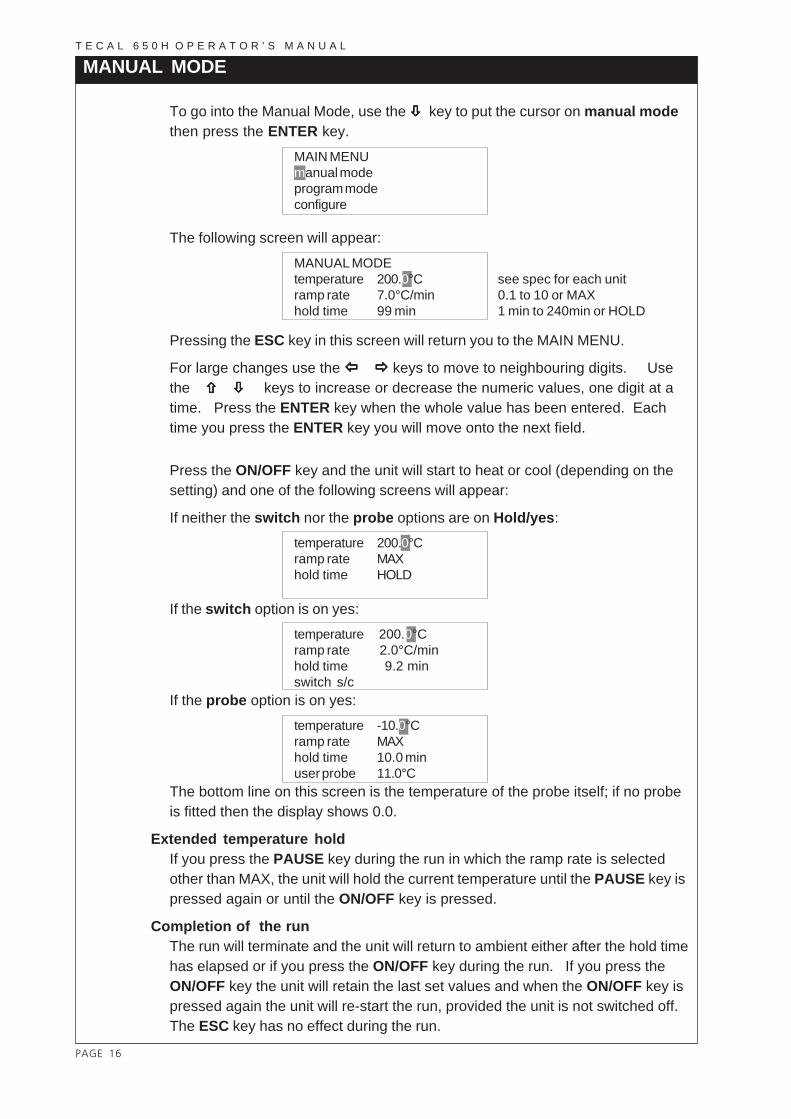
MANUAL MODE
To go into the Manual Mode, use the ##### key to put the cursor on manual modethen press the ENTER key.
MAIN MENUmanual modeprogram modeconfigure
The following screen will appear:MANUAL MODEtemperature 200.0°C see spec for each unitramp rate 7.0°C/min 0.1 to 10 or MAXhold time 99 min 1 min to 240min or HOLD
Pressing the ESC key in this screen will return you to the MAIN MENU.
For large changes use the $ %$ %$ %$ %$ % keys to move to neighbouring digits. Usethe " # " # " # " # " # keys to increase or decrease the numeric values, one digit at atime. Press the ENTER key when the whole value has been entered. Eachtime you press the ENTER key you will move onto the next field.
Press the ON/OFF key and the unit will start to heat or cool (depending on thesetting) and one of the following screens will appear:
If neither the switch nor the probe options are on Hold/yes:temperature 200.0°Cramp rate MAXhold time HOLD
If the switch option is on yes:temperature 200.0°Cramp rate 2.0°C/minhold time 9.2 minswitch s/c
If the probe option is on yes:temperature -10.0°Cramp rate MAXhold time 10.0 minuser probe 11.0°C
The bottom line on this screen is the temperature of the probe itself; if no probeis fitted then the display shows 0.0.
Extended temperature holdIf you press the PAUSE key during the run in which the ramp rate is selectedother than MAX, the unit will hold the current temperature until the PAUSE key ispressed again or until the ON/OFF key is pressed.
Completion of the runThe run will terminate and the unit will return to ambient either after the hold timehas elapsed or if you press the ON/OFF key during the run. If you press theON/OFF key the unit will retain the last set values and when the ON/OFF key ispressed again the unit will re-start the run, provided the unit is not switched off.The ESC key has no effect during the run.

PAGE 17
T E C A L 6 5 0 H O P E R A T O R ’ S M A N U A L
PROGRAM MODE
To go into the Program Mode, use the ##### key to put the cursor on programmode then press the ENTER key.
MAIN MENUmanual modeprogram modeconfigure
The following screen will appear:PROGRAM MODErun programnew programdelete program
Pressing the ESC key in this screen will return you to the MAIN MENU.
Use the " #" #" #" #" # keys to move to option you require.
Press the ENTER key when you have selected the option you want.
The three options are explained in the next sections.
Run Program
If you have chosen run program, the following screens will appear:RUN PROGRAMname: TEST_PRG
Pressing the ESC key in this screen will return you to the Program Mode.
Use the " #" #" #" #" # keys to find the program you want to run. Press the ENTER keyto select it. The display will change to the Program Running display which isexplained later.
Other keys have no effect.
PAGE 18
T E C A L 6 5 0 H O P E R A T O R ’ S M A N U A L
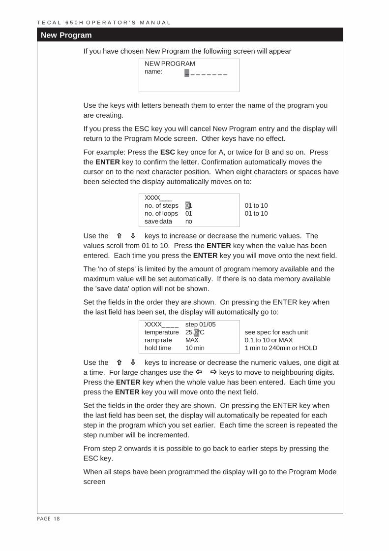
New Program
If you have chosen New Program the following screen will appearNEW PROGRAMname: _ _ _ _ _ _ _ _
Use the keys with letters beneath them to enter the name of the program youare creating.
If you press the ESC key you will cancel New Program entry and the display willreturn to the Program Mode screen. Other keys have no effect.
For example: Press the ESC key once for A, or twice for B and so on. Pressthe ENTER key to confirm the letter. Confirmation automatically moves thecursor on to the next character position. When eight characters or spaces havebeen selected the display automatically moves on to:
XXXX____no. of steps 01 01 to 10no. of loops 01 01 to 10save data no
Use the " #" #" #" #" # keys to increase or decrease the numeric values. Thevalues scroll from 01 to 10. Press the ENTER key when the value has beenentered. Each time you press the ENTER key you will move onto the next field.
The 'no of steps' is limited by the amount of program memory available and themaximum value will be set automatically. If there is no data memory availablethe 'save data' option will not be shown.
Set the fields in the order they are shown. On pressing the ENTER key whenthe last field has been set, the display will automatically go to:
XXXX_ _ _ _ step 01/05temperature 25.0°C see spec for each unitramp rate MAX 0.1 to 10 or MAXhold time 10 min 1 min to 240min or HOLD
Use the " #" #" #" #" # keys to increase or decrease the numeric values, one digit ata time. For large changes use the $ %$ %$ %$ %$ % keys to move to neighbouring digits.Press the ENTER key when the whole value has been entered. Each time youpress the ENTER key you will move onto the next field.
Set the fields in the order they are shown. On pressing the ENTER key whenthe last field has been set, the display will automatically be repeated for eachstep in the program which you set earlier. Each time the screen is repeated thestep number will be incremented.
From step 2 onwards it is possible to go back to earlier steps by pressing theESC key.
When all steps have been programmed the display will go to the Program Modescreen

PAGE 19
T E C A L 6 5 0 H O P E R A T O R ’ S M A N U A L
Program Running Display
The Display will automatically go into the the program running display asdescribed earlier.
One of the following screens will appear:
If neither the switch nor the probe options are on yes:
temperature 200.0°Cramp rate MAXhold time HOLD
If the switch option is on Hold/yes:
temperature 200.0°Cramp rate 2.0°C/minhold time 9.2 minswitch s/c
If the probe option is on yes:temperature -10.0°Cramp rate MAXhold time 10.0 minuser probe 11.0°C
The bottom line on this screen is the temperature of the probe itself.
In any of these screens, except in Pause Mode (see below), press the ENTERkey and the display will go to:
XXXX_PRGstep 01/01loop 01/01switch o/c
If you press the ENTER key while this screen is displayed, except in PauseMade (see below), the screen will return to the appropriate program runningscreen above.
Extended temperature holdIf you press the PAUSE key during the run, if the Ramp Rate is not set to MAX,the unit will hold the current temperature, and show a 'P' in the bottom righthand corner of the display, until the PAUSE key is pressed again or until theON/OFF key is pressed.
Completion of the runThe run will terminate and the unit will return to ambient after the hold time haselapsed, or if the ON/OFF key has been pressed before the end of the run. Ifyou press the ON/OFF key the unit will retain the last set values and when theON/OFF key is pressed again the unit will re-start the run. The ESC key has noeffect during the run.

PAGE 20
T E C A L 6 5 0 H O P E R A T O R ’ S M A N U A L
Switch Test
The switch test indicates the switch point temperature of a thermostat bydetecting the making or breaking of the circuit made by the contacts of thethermostat.
In Manual or Program Mode, the last line of the LCD indicates whether theSwitch is open or closed.
If the test is set to Switch Hold when a change is detected (except when theRamp Rate is set to MAX), the run is put into pause mode, and the letter 'P'appears at the bottom right hand corner of the display. Either stop the run bypressing the ON/OFF key, to return the unit to ambient temperature, or restartby pressing PAUSE, to continue heating or cooling.
If the test is set to switch, when a change is detected, the run continues cyclingto the set point temperature.
Note that it is not possible for both "User Probe" and "Switch" tests to be activeat the same time; selecting one automatically disables the other.
Positive connection Negative connection
(Red) (Black)

PAGE 21
T E C A L 6 5 0 H O P E R A T O R ’ S M A N U A L
Program Delete
PROGRAM MODErun programnew programdelete program
To go into the Program Delete Mode from the Program Mode screen, use the #####key to put the cursor on delete program then press the ENTER key.
The following screen will appear:DELETE PROGRAMname: TEST_PRG
Pressing the ESC key in this screen will return you to the Program Mode withoutdeleting a program.
Use the " #" #" #" #" # keys to find the program you want to delete. Press the ENTERkey to select it.
Other keys have no effect.
The following screens will appear:DELETE PROGRAMname: TEST_PRGare you sure? no
Use the " #" #" #" #" # keys to select 'yes'or 'no'.
Press the ENTER key to:
either
delete the program;
or
leave the program intact.
In both cases you will return to the Program Mode display.
Other keys have no effect.

PAGE 22
T E C A L 6 5 0 H O P E R A T O R ’ S M A N U A L
Cooling Probe
Operating temperatures below ambient can be achieved by using the coolingprobe with a chilled water circulator. The cooling probe is supplied as anaccessory and can be used in an insert with a 3/8" or 10mm hole (seeAccessories). Instructions for its use are included with the probe.
The block should not be operated at temperatures below dewpoint as excessivebuild up of moisture will occur which may cause damage to the interior of theunit.
After Use
1. When you have finished heating samples, remember that parts of theunit – inserts and associated accessories – may be very hot. Take theprecautions listed earlier. We recommend that the inserts should beallowed to cool to 70°C before being removed from the Tecal unit.They will still have to be handled with care
2. If you need to remove an insert while it is hot, fit the extractor tool intothe locating holes and lift the insert out carefully. Never leave theextractor tool in the insert while it is being used in the Tecal unit.

PAGE 23
T E C A L 6 5 0 H O P E R A T O R ’ S M A N U A L
RS232 SERIAL INTERFACEThe calibrator may send data logging information to an IBM PC or compatiblecomputer by connecting the unit and the PC via an RS232 cable, and installingthe "Calsoft" software supplied with each uit.
Ensure that there is a connection made before the calibrator is switchedon.
The RS232 cable must be fitted to both the unit and the PC before either unit ispowered up, otherwise, data integrity cannot be guaranteed. Once the cable isfitted, it does not matter which unit is powered up first.
RS232 9-way PC serial port
ON/OFF switch
Fuses Power inlet
The following table indicates the cable specifications for a 9-way PC serial port:
Calibrator PC9-way female D type 9-way female D typepin signal pinCase F.GND Case3 TxD 32 RxD 27 RTS 78 CTS 86 DSR 61 CD 14 DTR 45 S.GND 5
To Retrieve Test Results
In "Calsoft", select the name of the program whose test results you wish toretrieve and click the "Retrieve Program's Test Results" button. Save the testresults as a file name. Close the window; then view as a 'graph' or 'text' asappropriate.
To Retrieve a Program
In "Calsoft", select "Retrieve Program"; select the program name you wish toretrieve then click the "Retrieve Program" button.

PAGE 24
T E C A L 6 5 0 H O P E R A T O R ’ S M A N U A L
TECHNICAL INFORMATIONBrief fault finding notes and lists of replacement parts, accessories and insertsfor the Tecal units are given in this section.
NOTE THAT THIS EQUIPMENT SHOULD ONLY BE DISMANTLED BYPROPERLY TRAINED PERSONNEL. REMOVING THE OUTER COVERS ORBASE EXPOSES POTENTIALLY LETHAL MAINS VOLTAGES.
THERE ARE NO OPERATOR SERVICEABLE PARTS WITHIN THEEQUIPMENT.
General advice
In the unlikely event that you experience any problems with your Tecal whichcannot be easily remedied, you should contact your supplier and return the unitif necessary. Please include any details of the fault observed and remember toreturn the unit in its original packing. The insert must be removed from the unitand packed separately within the case. Techne accept no responsibility fordamage to units which are not properly packed for shipping: if in doubt, contactyour supplier.
General fault finding
Over temperature cutoutYour Tecal unit is fitted with two independent circuits to protect it fromoverheating. The unit constantly checks that the block temperature does notexceed its maximum. If for some reason this temperature is exceeded, allpower to the block is cut.Allow the unit to cool to a safe temperature (less than 100°C) before switchingoff and check for any obvious causes of overheating before switching it back on.Switching off the mains power resets the over-temperature cutout.
Repeated cutouts indicate a serious fault and you should return the unit to yoursupplier for repair.
Cleaning your Tecal unitBefore cleaning your unit, disconnect from the power supply and allow to cool toambient temperature.
You can clean the case of theTecal with a cloth dipped in water or ethanol(methanol can also be used). No part of the case or cover should be immersedin the solvents.
Do not use acetone or abrasive cleaners.
HELP displayIf HELP is displayed there is a problem with the internal sensing device. Thecalibrator should be returned to your supplier for repair.
FusesIf neither the power light nor display (on the front panel) is lit, one of the twofuses may have blown. Make sure there is no external cause (such as a faultyplug or lead).

PAGE 25
T E C A L 6 5 0 H O P E R A T O R ’ S M A N U A L
Fuses should only be changed by suitably qualified personnel. If the fuses blowpersistently, a serious fault is indicated and you should return the calibrator toyour supplier for repair.
Never fit a fuse rated higher than the value indicated on the unit, seriousdamage or personal injury may result.
Replacement parts
Each unit is supplied with an extraction tool, a carrying case and a mains cable.The following parts may be purchased if replacements or alternatives arerequired.
Part Nº Description
6100121 Insert extractorFCAB10UK Mains cable, 230V UK unitsFCABLEEU Mains cable, 230V unitsFCABLEUS Mains cable, 120/100V units6103711 Soft carrying case
Accessories
Part Nº DescriptionFPRINTD Probe interface 230Vwith UK plugFPRINTE Probe interface 230V with European plugFPRINTP Probe interface 120V with US plugFDB00CP Cooling ProbeFCAL232 PC software kit

PAGE 26
T E C A L 6 5 0 H O P E R A T O R ’ S M A N U A L
Inserts
Inserts are made from aluminium or aluminium-bronze and must be orderedseparately from the calibrator. Each insert is stamped for identification.
A blank insert is available which may be drilled to suit your application.
Immersion depth 152.4 mm or 6"
NUMBER PROBE DIAMETERMETRICFINSABA 5 off 6mmFINSABB 1 off each 10mm, 8mm, 6mm, 4.5mm, 3mmFINSABC 2 off 6mm, 2 off 10mmFINSABD 2 off 6mm, 2 off 12mmFINSABE 1 off 6mmFINSABZ 1 off 20mmIMPERIALFINSABF 5 off 1/4"FINSABG 1 off each 3/8", 5/16", 1/4", 3/16", 1/8"FINSABH 2 off 1/4", 2 off 3/8"FINSABI 2 off 1/4", 2 off 1/2"FINSABJ 1 off 1/4"FINSABL 1 off 9/16"FINSABM 1 off 5/8"FINSABN 1 off 3/4"FINSABO 1 off 11/16"BLANKFINSABK BLANK

PAGE 27
T E C A L 6 5 0 H O P E R A T O R ’ S M A N U A L
GLOSSARY
Block temp. The current temperature of the heat transferblock.
Cursor The flashing bar on the LCD screen whichindicates where the next character is entered.
Hold time The duration for which the block is maintainedat a given temperature. Note that the clockcounter which measures the hold time isstarted when the temperature is within 2°C ofthe set point temperature.
Pause When you press the PAUSE button, theprogram halts but maintains the block at thetemperature reached immediately before thekey was pressed. (Note that it takes severalminutes for the temperature of the block toreach equilibrium.) Press the PAUSE buttonagain to continue.
Program A program is made up of a sequence ofsegments. The sequence may be executedonce or several times
PRT Platinum Resistance Thermometer.
Ramp rate The rate at which the block is heated or cooled.
Set Point Temp. The temperature to which the calibrator isset to control.
r_sanchez
New Stamp

PAGE 28
T E C A L 6 5 0 H O P E R A T O R ’ S M A N U A L