TEC3000 Series Field-Selectable BACnet® MS/TP or N2 ... Thermostats_Controllers/PDFs/JCI...
38
Refer to the QuickLIT website for the most up-to-date version of this document. TEC3000 Series Field-Selectable BACnet® MS/TP or N2 Networked Thermostat Controllers Technical Bulletin 1 Introduction . . . . . . . . . . . . . . . . . . . . . . . . . . . . . . . . . . . . . . . . . . . . . . . . . . . . . . . . . . . . . . . . 3 Summary of Changes . . . . . . . . . . . . . . . . . . . . . . . . . . . . . . . . . . . . . . . . . . . . . . . . . . . . . . . . 3 Product Overview . . . . . . . . . . . . . . . . . . . . . . . . . . . . . . . . . . . . . . . . . . . . . . . . . . . . . . . . . . . 4 Proportional Fan Coil and Zoning Thermostat Controllers . . . . . . . . . . . . . . . . . . . . . . . . . . . . . 4 On/Off or Floating Fan Coil and Zoning Thermostat Controllers . . . . . . . . . . . . . . . . . . . . . . . . 5 Single- or Two-Stage RTU/Heat Pump with Economizer Thermostat Controllers. . . . . . . . . . . 5 Model Names and Code Numbers . . . . . . . . . . . . . . . . . . . . . . . . . . . . . . . . . . . . . . . . . . . . . . . . . 6 Determining Proper Pairing of CPU Board and Base Board . . . . . . . . . . . . . . . . . . . . . . . . . . . . . . . 6 Configuring MS/TP or N2 Bus . . . . . . . . . . . . . . . . . . . . . . . . . . . . . . . . . . . . . . . . . . . . . . . . . 7 Wiring the Network . . . . . . . . . . . . . . . . . . . . . . . . . . . . . . . . . . . . . . . . . . . . . . . . . . . . . . . . . . . . . 7 End-of-Line Termination . . . . . . . . . . . . . . . . . . . . . . . . . . . . . . . . . . . . . . . . . . . . . . . . . . . . . . . . . 7 Setting the Network Parameters. . . . . . . . . . . . . . . . . . . . . . . . . . . . . . . . . . . . . . . . . . . . . . . . . . . 7 Connecting the MS/TP or N2 Bus . . . . . . . . . . . . . . . . . . . . . . . . . . . . . . . . . . . . . . . . . . . . . . . . . . 8 MS/TP or N2 Thermostat Controller Mapping . . . . . . . . . . . . . . . . . . . . . . . . . . . . . . . . . . . . . . . . 8 Preparation . . . . . . . . . . . . . . . . . . . . . . . . . . . . . . . . . . . . . . . . . . . . . . . . . . . . . . . . . . . . . . . . . . . . 8 Adding a Thermostat Controller . . . . . . . . . . . . . . . . . . . . . . . . . . . . . . . . . . . . . . . . . . . . . . . . . . . . . 9 Adding BACnet MS/TP Points . . . . . . . . . . . . . . . . . . . . . . . . . . . . . . . . . . . . . . . . . . . . . . . . . . . . . . 9 Adding N2 Points . . . . . . . . . . . . . . . . . . . . . . . . . . . . . . . . . . . . . . . . . . . . . . . . . . . . . . . . . . . . . . . . 9 Remapping Points . . . . . . . . . . . . . . . . . . . . . . . . . . . . . . . . . . . . . . . . . . . . . . . . . . . . . . . . . . . . . . . 9 MS/TP or N2 Bus Points Tables . . . . . . . . . . . . . . . . . . . . . . . . . . . . . . . . . . . . . . . . . . . . . . . 10 Thermostat Controllers . . . . . . . . . . . . . . . . . . . . . . . . . . . . . . . . . . . . . . . . . . . . . . . . . . . . . . . . 10 Scheduling . . . . . . . . . . . . . . . . . . . . . . . . . . . . . . . . . . . . . . . . . . . . . . . . . . . . . . . . . . . . . . . . 22 Commanding Objects from a Supervisory Controller . . . . . . . . . . . . . . . . . . . . . . . . . . . . . 23 Menu and Submenu Descriptions . . . . . . . . . . . . . . . . . . . . . . . . . . . . . . . . . . . . . . . . . . . . . 24 Setpoints. . . . . . . . . . . . . . . . . . . . . . . . . . . . . . . . . . . . . . . . . . . . . . . . . . . . . . . . . . . . . . . . . . . . . 24 TEC3000 Series Field-Selectable BACnet® MS/TP or N2 Networked Thermostat Controllers Technical Bulletin Code No. LIT-12011956 Issued December 2016
Transcript of TEC3000 Series Field-Selectable BACnet® MS/TP or N2 ... Thermostats_Controllers/PDFs/JCI...

Refer to the QuickLIT website for the most up-to-date version of this document.
TEC3000 Series Field-Selectable BACnet® MS/TP or N2 Networked Thermostat Controllers Technical Bulletin Code No. LIT-12011956
Issued December 2016
Introduction . . . . . . . . . . . . . . . . . . . . . . . . . . . . . . . . . . . . . . . . . . . . . . . . . . . . . . . . . . . . . . . .3
Summary of Changes . . . . . . . . . . . . . . . . . . . . . . . . . . . . . . . . . . . . . . . . . . . . . . . . . . . . . . . .3
Product Overview . . . . . . . . . . . . . . . . . . . . . . . . . . . . . . . . . . . . . . . . . . . . . . . . . . . . . . . . . . .4
Proportional Fan Coil and Zoning Thermostat Controllers . . . . . . . . . . . . . . . . . . . . . . . . . . . . . 4
On/Off or Floating Fan Coil and Zoning Thermostat Controllers . . . . . . . . . . . . . . . . . . . . . . . . 5
Single- or Two-Stage RTU/Heat Pump with Economizer Thermostat Controllers. . . . . . . . . . . 5
Model Names and Code Numbers . . . . . . . . . . . . . . . . . . . . . . . . . . . . . . . . . . . . . . . . . . . . . . . . . 6
Determining Proper Pairing of CPU Board and Base Board . . . . . . . . . . . . . . . . . . . . . . . . . . . . . . . 6
Configuring MS/TP or N2 Bus . . . . . . . . . . . . . . . . . . . . . . . . . . . . . . . . . . . . . . . . . . . . . . . . .7
Wiring the Network . . . . . . . . . . . . . . . . . . . . . . . . . . . . . . . . . . . . . . . . . . . . . . . . . . . . . . . . . . . . . 7
End-of-Line Termination . . . . . . . . . . . . . . . . . . . . . . . . . . . . . . . . . . . . . . . . . . . . . . . . . . . . . . . . . 7
Setting the Network Parameters. . . . . . . . . . . . . . . . . . . . . . . . . . . . . . . . . . . . . . . . . . . . . . . . . . . 7
Connecting the MS/TP or N2 Bus. . . . . . . . . . . . . . . . . . . . . . . . . . . . . . . . . . . . . . . . . . . . . . . . . . 8
MS/TP or N2 Thermostat Controller Mapping . . . . . . . . . . . . . . . . . . . . . . . . . . . . . . . . . . . . . . . . 8
Preparation . . . . . . . . . . . . . . . . . . . . . . . . . . . . . . . . . . . . . . . . . . . . . . . . . . . . . . . . . . . . . . . . . . . . 8
Adding a Thermostat Controller . . . . . . . . . . . . . . . . . . . . . . . . . . . . . . . . . . . . . . . . . . . . . . . . . . . . . 9
Adding BACnet MS/TP Points . . . . . . . . . . . . . . . . . . . . . . . . . . . . . . . . . . . . . . . . . . . . . . . . . . . . . . 9
Adding N2 Points . . . . . . . . . . . . . . . . . . . . . . . . . . . . . . . . . . . . . . . . . . . . . . . . . . . . . . . . . . . . . . . . 9
Remapping Points . . . . . . . . . . . . . . . . . . . . . . . . . . . . . . . . . . . . . . . . . . . . . . . . . . . . . . . . . . . . . . . 9
MS/TP or N2 Bus Points Tables . . . . . . . . . . . . . . . . . . . . . . . . . . . . . . . . . . . . . . . . . . . . . . .10
Thermostat Controllers . . . . . . . . . . . . . . . . . . . . . . . . . . . . . . . . . . . . . . . . . . . . . . . . . . . . . . . . 10
Scheduling . . . . . . . . . . . . . . . . . . . . . . . . . . . . . . . . . . . . . . . . . . . . . . . . . . . . . . . . . . . . . . . .22
Commanding Objects from a Supervisory Controller . . . . . . . . . . . . . . . . . . . . . . . . . . . . .23
Menu and Submenu Descriptions . . . . . . . . . . . . . . . . . . . . . . . . . . . . . . . . . . . . . . . . . . . . .24
Setpoints. . . . . . . . . . . . . . . . . . . . . . . . . . . . . . . . . . . . . . . . . . . . . . . . . . . . . . . . . . . . . . . . . . . . . 24
TEC3000 Series Field-Selectable BACnet® MS/TP or N2 Networked Thermostat Controllers Technical Bulletin
1

Schedule Options . . . . . . . . . . . . . . . . . . . . . . . . . . . . . . . . . . . . . . . . . . . . . . . . . . . . . . . . . . . . . 25
Display Settings . . . . . . . . . . . . . . . . . . . . . . . . . . . . . . . . . . . . . . . . . . . . . . . . . . . . . . . . . . . . . . . 25
Control Setup . . . . . . . . . . . . . . . . . . . . . . . . . . . . . . . . . . . . . . . . . . . . . . . . . . . . . . . . . . . . . . . . . 26
General . . . . . . . . . . . . . . . . . . . . . . . . . . . . . . . . . . . . . . . . . . . . . . . . . . . . . . . . . . . . . . . . . . . . . . 26
Inputs . . . . . . . . . . . . . . . . . . . . . . . . . . . . . . . . . . . . . . . . . . . . . . . . . . . . . . . . . . . . . . . . . . . . . . . . 27
Network Setup . . . . . . . . . . . . . . . . . . . . . . . . . . . . . . . . . . . . . . . . . . . . . . . . . . . . . . . . . . . . . . . . 27
Equipment Setup . . . . . . . . . . . . . . . . . . . . . . . . . . . . . . . . . . . . . . . . . . . . . . . . . . . . . . . . . . . . . . 28
General . . . . . . . . . . . . . . . . . . . . . . . . . . . . . . . . . . . . . . . . . . . . . . . . . . . . . . . . . . . . . . . . . . . . . . 28
Supply Fan. . . . . . . . . . . . . . . . . . . . . . . . . . . . . . . . . . . . . . . . . . . . . . . . . . . . . . . . . . . . . . . . . . . . 28
Reheat . . . . . . . . . . . . . . . . . . . . . . . . . . . . . . . . . . . . . . . . . . . . . . . . . . . . . . . . . . . . . . . . . . . . . . . 28
Economizer . . . . . . . . . . . . . . . . . . . . . . . . . . . . . . . . . . . . . . . . . . . . . . . . . . . . . . . . . . . . . . . . . . . 29
Heat Pump . . . . . . . . . . . . . . . . . . . . . . . . . . . . . . . . . . . . . . . . . . . . . . . . . . . . . . . . . . . . . . . . . . . . 29
Changeover . . . . . . . . . . . . . . . . . . . . . . . . . . . . . . . . . . . . . . . . . . . . . . . . . . . . . . . . . . . . . . . . . . . 29
System Status . . . . . . . . . . . . . . . . . . . . . . . . . . . . . . . . . . . . . . . . . . . . . . . . . . . . . . . . . . . . . . . . . 29
Control Status . . . . . . . . . . . . . . . . . . . . . . . . . . . . . . . . . . . . . . . . . . . . . . . . . . . . . . . . . . . . . . . . . 30
Trends . . . . . . . . . . . . . . . . . . . . . . . . . . . . . . . . . . . . . . . . . . . . . . . . . . . . . . . . . . . . . . . . . . . . . . . 30
Controller Info . . . . . . . . . . . . . . . . . . . . . . . . . . . . . . . . . . . . . . . . . . . . . . . . . . . . . . . . . . . . . . . . . 31
Commissioning . . . . . . . . . . . . . . . . . . . . . . . . . . . . . . . . . . . . . . . . . . . . . . . . . . . . . . . . . . . . . . . . 31
Update . . . . . . . . . . . . . . . . . . . . . . . . . . . . . . . . . . . . . . . . . . . . . . . . . . . . . . . . . . . . . . . . . . . . . . . 31
Troubleshooting . . . . . . . . . . . . . . . . . . . . . . . . . . . . . . . . . . . . . . . . . . . . . . . . . . . . . . . . .32
Related Documentation . . . . . . . . . . . . . . . . . . . . . . . . . . . . . . . . . . . . . . . . . . . . . . . . . . . . .37
TEC3000 Series Field-Selectable BACnet® MS/TP or N2 Networked Thermostat Controllers Technical Bulletin
2
TEC3000 Series Field-Selectable BACnet® MS/TP or N2 Networked Thermostat ControllersTechnical Bulletin
IntroductionThis document describes how to configure the various wired TEC3000 Series Thermostat Controllers for BACnet® Master-Slave/Token-Passing (MS/TP) or N2 networked applications, including how to:
• connect to the MS/TP or N2 Bus and map a thermostat controller into a Network Automation Engine (NAE)
• add a thermostat controller
• add points
• command and configure from an NAE
• troubleshoot the thermostat controller
Summary of ChangesThe following information is new or revised:
• updated Point Names throughout the document
• added Remapping Points section
• added the Scheduling section
• added additional setpoints
• added Commanding Objects from a Supervisory Controller section
• Updated and added to the Troubleshooting section
TEC3000 Series Field-Selectable BACnet® MS/TP or N2 Networked Thermostat Controllers Technical Bulletin
3
Product OverviewThe technologically advanced TEC3000 Series Thermostat Controllers feature a Building Automation System (BAS) BACnet MS/TP or N2 communication capability that enables remote monitoring and programming for efficient space temperature control. The TEC3000 Series Thermostat Controllers feature an intuitive user interface with backlit display that makes setup and operation quick and easy.
In addition, the configuration can be backed up to a USB drive and restored to like models to help expedite the commissioning process. Refer to the TEC3000 Series Proportional Fan Coil and Zoning Thermostat Controllers with Dehumidification Capability Installation Instructions (Part No. 24-10788-0), TEC3000 Series On/Off or Floating Fan Coil and Zoning Thermostat Controllers with Dehumidification Capability Installation Instructions (Part No. 24-10787-6), or TEC3000 Series Single- or Two-Stage Economizer Thermostat Controllers Installation Instructions (Part No. 24-10789-5) for information on using the USB drive.
The TEC3000 Series Thermostat Controllers are BACnet MS/TP or N2 networked devices that provide control of:
• rooftop units (with or without economizers)
• heat pumps
• single- and multi-stage heating and cooling equipment
• humidification and dehumidification equipment
• two- or four-pipe fan coils
• cabinet unit heaters
• local hydronic reheat valves
• pressure-dependent Variable Air Volume (VAV) equipment with or without local reheat
• other zoning equipment using an on/off, floating, or proportional 0 to 10 VDC control input
Proportional Fan Coil and Zoning Thermostat ControllersThe TEC3000 Series Proportional Fan Coil and Zoning Thermostat Controllers are field-selectable and BACnet Master-Slave/Token-Passing (MS/TP) or N2 networked devices provide control of:
• local hydronic reheat valves
• pressure-dependent VAV equipment with or without local reheat
• two- or four-pipe fan coils
• cabinet unit heaters
• other zoning equipment using a proportional 0 to 10 VDC control input
The networked models feature a BAS BACnet MS/TP or N2 communication capability that enables remote monitoring and programming for efficient space temperature control.
Some models have occupancy sensing capability built into the device. These thermostat controllers maximize up to 30% energy savings in high-energy usage, light commercial buildings, such as schools and hotels. This is during occupied times by using additional standby setpoints when occupants are not in the room.
All models feature an intuitive UI with backlit display that makes setup and operation quick and easy. Multiple fan configurations are supported for all equipment types.
• single-speed
• multi-speed (two or three discrete speeds)
• variable-speed/EC motors (0 to 10 VDC control)
Models with a built-in humidity sensor support dehumidification on two-pipe fan coil units with reheat, and four-pipe fan coil units with or without reheat. When no heating is required, the thermostat controller monitors space humidity and activates dehumidification control as necessary. Heat and/or reheat is used as required to maintain the space temperature. For optimal dehumidification performance, use a fan coil unit that has a multi-speed or variable-speed fan.
TEC3000 Series Field-Selectable BACnet® MS/TP or N2 Networked Thermostat Controllers Technical Bulletin
4

On/Off or Floating Fan Coil and Zoning Thermostat ControllersThe TEC3000 Series On/Off or Floating Fan Coil and Zoning Thermostat Controllers are field-selectable BACnet MS/TP or N2 networked devices provide control of:
• local hydronic reheat valves
• pressure-dependent VAV equipment with or without local reheat
• two- or four-pipe fan coils
• cabinet unit heaters
• other zoning equipment using an on/off or floating control input
The networked models feature a BAS BACnet MS/TP or N2 communication capability that enables remote monitoring and programming for efficient space temperature control.
Some models have occupancy sensing capability built into the device. These thermostat controllers maximize up to 30% energy savings in high-energy usage, light commercial buildings, such as schools and hotels, during occupied times by using additional standby setpoints.
All models feature a UI with backlit display that makes setup and operation quick and easy. Multiple fan configurations are supported for all equipment types.
• single-speed
• multi-speed (two or three discrete speeds)
• variable-speed/EC motors (0 to 10 VDC control)
Models with a built-in humidity sensor support dehumidification on two-pipe fan coil units with reheat, and four-pipe fan coil units with or without reheat. When no heating is required, the thermostat controller monitors space humidity and activates dehumidification control as necessary. Heat and/or reheat is used as required to maintain the space temperature. For optimal dehumidification performance, use a fan coil unit that has a multi-speed or variable-speed fan.
Single- or Two-Stage RTU/Heat Pump with Economizer Thermostat ControllersThe TEC3000 Series Single- or Two-Stage Economizer Thermostat Controllers are field-selectable BACnet MS/TP or N2 networked devices provide control of:
• unitary rooftop units (RTUs)
• unitary RTUs with economizers
• unitary RTUs with heat pumps
• unitary RTUs with economizers and heat pumps
The networked models feature a BAS BACnet MS/TP or N2 communication capability that enables remote monitoring and programming for efficient space temperature control.
Some models have occupancy sensing capability built into the device. These thermostat controllers maximize up to 30% energy savings in high-energy usage, light commercial buildings, such as schools and hotels, during occupied times by using additional standby setpoints.
All models feature an intuitive UI with backlit display that makes setup and operation quick and easy. Only the single-speed fan configuration is supported for fan coil equipment types.
TEC3000 Series Field-Selectable BACnet® MS/TP or N2 Networked Thermostat Controllers Technical Bulletin
5
Model Names and Code Numbers
Determining Proper Pairing of CPU Board and Base Board
Figure 1: Error Code Indicating Mismatched Boards
Table 1: TEC3000 Model Names and Code NumbersName Code Number Name Code Number
TEC3310 00 TEC3610 0A
TEC3311 01 TEC3611 0B
TEC3312 02 TEC3612 0C
TEC3313 03 TEC3613 0D
TEC3320 04 TEC3620 0E
TEC3321 05 TEC3621 0F
TEC3322 06 TEC3622 10
TEC3323 07 TEC3623 11
TEC3330 08 TEC3630 12
TEC3331 09 TEC3631 13
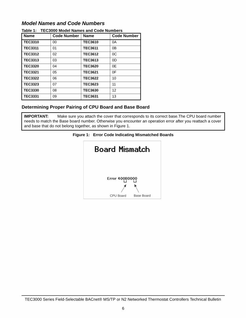
IMPORTANT: Make sure you attach the cover that corresponds to its correct base.The CPU board number needs to match the Base board number. Otherwise you encounter an operation error after you reattach a cover and base that do not belong together, as shown in Figure 1.
CPU Board Base Board
TEC3000 Series Field-Selectable BACnet® MS/TP or N2 Networked Thermostat Controllers Technical Bulletin
6

Configuring MS/TP or N2 BusThe TEC3000 supports network connectivity to a BAS using a BACnet MS/TP or N2 Bus. BACnet MS/TP or N2 communication is selected through the software and both protocols use the same wiring.
Wiring the NetworkN2 and BACnet MS/TP protocols run over the same wiring. The physical connection is an RS-485 connection, requiring three connections:
• NET +
• NET -
• NET COM
Connect the TEC3000 in line with other devices on the network.
End-of-Line TerminationWhen the TEC3000 is the last device on the bus, make sure the end-of-line (EOL) switch on the I/O board is in the On position.
Figure 2: EOL Switch Positions
Setting the Network ParametersAll network configuration is done through the software. On the home screen, click the menu icon. Scroll down to Network Setup for the network settings. Out of the box, the thermostat is configured in BACnet MS/TP mode. To change to the N2 mode, select FC Comm Mode and change to N2. This change reboots the device when you click the save icon.
FIG
:TE
C B
ackp
lane
2_E
OL
Switc
h
ON
TEC3000 Series Field-Selectable BACnet® MS/TP or N2 Networked Thermostat Controllers Technical Bulletin
7

Connecting the MS/TP or N2 BusTo connect the MS/TP or N2 Bus:
1. Set the MS/TP or N2 address of the TEC3000 Series BACnet MS/TP or N2 Network Temperature and Humidity Thermostat Controller according to the engineering drawings.
Note: For more details on wiring the MS/TP Communications Bus, refer to the MS/TP Communications Bus Technical Bulletin (LIT-12011034).
2. Observe the polarity when connecting the bus wires to the thermostat controller.
3. After the bus wires are connected to the first thermostat controller, continue in a daisy-chained fashion to the next thermostat controller.
Note: The bus wiring must be twisted-pair lines. Do not run the bus wiring in the same conduit as line voltage wiring (30 VAC or above) or other wiring that switches power to highly inductive loads (such as contactors, coils, motors, or generators).
The thermostat controller should be configured for automatic baud rate detection. Do not exceed the maximum number of devices allowed on a field bus. Be sure that the wiring terminations are set correctly and that all communication wiring is daisy-chained with no taps.
MS/TP or N2 Thermostat Controller Mapping
Preparation
Before you map a TEC3000 Series field-selectable BACnet MS/TP or N2 Network Thermostat Controller into an NAE:
1. Decide which points within the thermostat controller need to be mapped. Only map the points that need to be viewed or commanded on a regular basis, or required alarm or trend extension. Excessive mapping lowers system performance. Suggested points for mapping include Zone Temp, System Mode, Fan Mode, Manual Occupancy Mode, Occupied Heating Setpoint, Occupied Cooling Setpoint, Unoccupied Heating Setpoint, and Unoccupied Cooling Setpoint. In addition, alarm points may be mapped if they are used, and other points may be mapped if required. Use the Engineering view to examine infrequently used points.
Table 2: Setup MenusMenu Parameter Description
BACnet Instance ID This is the instance ID of the device on the BACnet MS/TP bus. BACnet MS/TP systems use the instance ID for identification of the device. It can be set from 1 to 4,194,303 an is unique to that site. The default is 1.
BACnet Device Address This is the physical MAC address of the BACnet MS/TP device on the bus. It can be set from 4 to 127. Two devices on the same bus cannot have the same BACnet MS/TP device address. The default is 4.
MSTP Baud Rate This is the baud rate that the TEC communicates on the network. The default value is Auto, which allows the device to automatically detect the baud rate of the BACnet MS/TP bus and operate at that speed. An incorrect value causes the device to not communicate on the network, and can potentially cause the network to fail. Options for this setting are Auto, 1,200, 9,600, 19,200, 38,400, and 76,800 Baud.
BACnet Encoding Type This is the method of data encoding and is used by the BACnet MS/TP bus. The default value, ISO 10646 (UCS-2), is the encoding used by the Metasys® platform. When operating on a third-party BAS, refer to the documentation provided with the BAS for the proper encoding type.
N2 Device Address This is the physical MAC address of the N2 device on the bus and can be set from 1 to 255. Two devices on the same bus cannot have the same N2 device address.
TEC3000 Series Field-Selectable BACnet® MS/TP or N2 Networked Thermostat Controllers Technical Bulletin
8

Note: We recommend that all thermostat controller configuration parameters be set as desired before you map the points into the NAE. If any thermostat controller configuration parameters are altered after the points are mapped into the thermostat controller, re-map all points individually, because some exposed points might have been added or removed. Be careful when you map configuration parameters, because they should only be mapped if the operator is fully familiar with their use.
2. Verify that a Field Bus is defined in the NAE. BACnet MS/TP or N2 devices attach to a Field Bus. Refer to the Metasys N2 Communication Bus Technical Bulletin (LIT-636018) for instructions on how to define a Field Bus.
3. For Metasys system software earlier than Release 4.0, verify that a BACnet Integration is defined for the Field Bus. The thermostat controllers are mapped as BACnet MS/TP devices under a Field Bus BACnet Integration. Refer to the BACnet Controller Integration with NAE/NCE Technical Bulletin (LIT-1201531) or the Metasys N2 Communication Bus Technical Bulletin (LIT-636018) for instructions on how to define a BACnet Integration.
Note: Metasys system Release 7.0.2 or later software is required for proper support of text strings on all network points.
At this point, the thermostat controller (and the required points inside the thermostat controller) can be mapped.
Adding a Thermostat Controller
The thermostat controller must be added before its points can be mapped. To add the thermostat controller, select either the Field or N2 Bus and choose Field Device from the Insert menu.
Assisted Definition using Auto Discovery is the easiest way to add a new thermostat controller online; however, this method requires that the thermostat controller to be added is connected and ready to communicate. Device addresses must be unique from 4 to 127 for the BACnet MS/TP and 1 to 255 for the N2 network.
Adding BACnet MS/TP Points
The required points must be mapped under the thermostat controller device. To map the points, select the thermostat controller device under the BACnet Integration (refresh the tree view if required to see a newly added thermostat controller device) and choose Field Point from the Insert menu.
Assisted Definition using Auto Discovery is the easiest way to add new points online; however, this function requires that the thermostat controller that is to be mapped is connected and ready to communicate. When mapping points offline, the point type must match the BACnet object type (for example, AV, MV, BI), and the point instance number must match the point BACnet instance number.
Adding N2 Points
The required points must be mapped under the thermostat controller device. To map the points, select the thermostat controller device under the N2 Integration (refresh the tree view if required to see a newly added thermostat controller device) and choose Field Point from the Insert menu.
You then need to add the appropriate PRN file based on the TEC model being used. Multi-state points are defined as ADI points in the PRN file. These must be mapped using either MI or MO NAE object types. Following the field point addition object units may need further tailoring of units and enum set values. See Table 3, Table 4, or Table 5 for the enum set values.
Remapping Points
When you need to remap a TEC3000 Thermostat Controller to an NAE at the same FC bus address, you need to select the displayed field points individually in the Point Mapping Utility. There are 60 field points that you can select.
TEC3000 Series Field-Selectable BACnet® MS/TP or N2 Networked Thermostat Controllers Technical Bulletin
9

MS/TP or N2 Bus Points Tables
Thermostat Controllers
Table 3: Points for TEC3610-0x-000, TEC3611-0x-000, TEC3612-0x-000, TEC3613-0x-000 (Part 1 of 4)
Point Name Thermostat Point(Type/Instance ID)
N2 Point Type and Address
Enum Set/Range
Control Mode (SYSTEM-MODE) MV29500 MI1 TEC3000 Unit Control Mode• 1 - Auto• 2 - Cooling• 3 - Heating
Unit Enable (UNITEN-MODE) MV29501 MI2 Shutdown/Enable• 1 - Shutdown• 2 - Enable
Occupied Cooling Setpoint (CLGOCC-SP)
AV29502 AO1 60 to 100°F (15 to 38°C)
Occupied Heating Setpoint (HTGOCC-SP)
AV29503 AO2 45 to 85°F (7 to 30°C)
Unoccupied Cooling Setpoint (CLGUNOCC-SP)
AV29504 AO3 60 to 100°F (15 to 38°C)
Unoccupied Heating Setpoint (HTGUNOCC-SP)
AV29505 AO4 45 to 85°F (7 to 30°C)
Standby Cooling Setpoint (CLGSTBY-SP)
AV29506 AO5 60 to 100°F (15 to 38°C)
Standby Heating Setpoint (HTGSTBY-SP)
AV29507 AO6 45 to 85°F (7 to 30°C)
Setpoint Offset (WC-ADJ) AV29508 AO7 0 to Max Setpoint Offset
Hold/Run (HOLDRUN-MD) MV29509 MI3 Hold Run• 1 - Hold• 2 - Run
Humidity Sp (ZNH-SP) AV29510 AI8 0 to 100% RH
Network Override Supply Air Temperature (NET-SAT)
AV29515 AI13 0 to 150°F (-18 to 65°C)
Dry Bulb Sp (DB-SP) AV29511 AI9 40 to 80°F (4 to 27°C)
OA Enthalpy SP (OAENTH-SP) AV29512 AI10 10 to 50 BTU/lb dry air (23 to 116 J/kg)
NetOAT (NET-OAT) AV29513 AI11 -50 to 125°F (-46 to 52°C)
NetOAH (NET-OAH) AV29514 AI12 0 to 100% RH
Reset PID Tuning (TUNING-RESET)
MV29517 MI4 No/Yes• 1 - No• 2 - Yes
Net ZNH (NET-ZNH) AV29516 AI14 0 to 100% RH
Manual Occ (OCCOVRD-MODE) MV29518 MI5 UI Occ Override• 1 - No Override• 2 - Occupied• 3 - Unoccupied
Supervisor Occupancy (NET-OCC) MV29519 MI6 Occ Base Set• 1 - Occupied• 2 - Unoccupied• 3 - Standby
Occupancy Configuration Source (OCC-CONFIG)
MV29520 MI7 SE Occupancy Mode• 1 - Schedule• 2 - External
TEC3000 Series Field-Selectable BACnet® MS/TP or N2 Networked Thermostat Controllers Technical Bulletin
10

Passcode (PASSCODE)1 AV29522 AI15 0000 to 9999
CgOvr Mode (CGOVR-MODE)
MV29523 MI8 TEC3000 Unit Control Mode• 1 - Auto• 2 - Cooling• 3 - Heating
Fan Mode (FAN-MODE) MV29524 MI9 TEC3000 Fan Mode• 1 - On• 2 - Auto• 3 - Smart
Fan Override (FANOVRD-MODE) MV29525 MI10 UI Fan Override• 1 - On• 2 - Auto• 3 - Quiet
Aux Mode (AUX-MODE) MV29527 MI11 TEC3000 Aux Mode• 1 - Not Used• 2 - Occupied NO• 3 - Occupied NC• 4 - Occupied Fan NO• 5 - Occupied Fan NC• 6 - On• 7 - Off
Temperature Units (TEMP-UNITS)
MV29528 MI12 Unit Set• 1 - IP• 2 - SI
Max Setpoint Offset (MAXSP-OFFSET)
AV29529 AI29 0 to 20°F (0 to 11°C)
Unit Status (UNIT-S) MV29700 MI13 TEC3000 Detailed Control Status • 1 - System Fault• 2 - Airflow Fault• 3 - Open Window• 4 - Control Off• 5 - Unreliable Temperature• 6 - Dehumidification• 7 - Idle• 8 - Cooling• 9 - Heating• 10 - Cooling Unavailable• 11 - Heating Unavailable• 12 - Cooling Unavailable due to
Changeover• 13 - Cooling Unavailable due to QA
Temp• 14 - Cooling Unavailable due to
Control Mode• 15 - Heating Unavailable due to
Changeover• 16 - Heating Unavailable due to QA
Temp• 17 - Heating Unavailable due to
Control Mode
Operational Space Temperature (EFF-ZNT)
AV29701 AI16 Not Applicable
Return Air Humidity (EFF-ZNH) AV29702 AI17 Not Applicable
Table 3: Points for TEC3610-0x-000, TEC3611-0x-000, TEC3612-0x-000, TEC3613-0x-000 (Part 2 of 4)
Point Name Thermostat Point(Type/Instance ID)
N2 Point Type and Address
Enum Set/Range
TEC3000 Series Field-Selectable BACnet® MS/TP or N2 Networked Thermostat Controllers Technical Bulletin
11
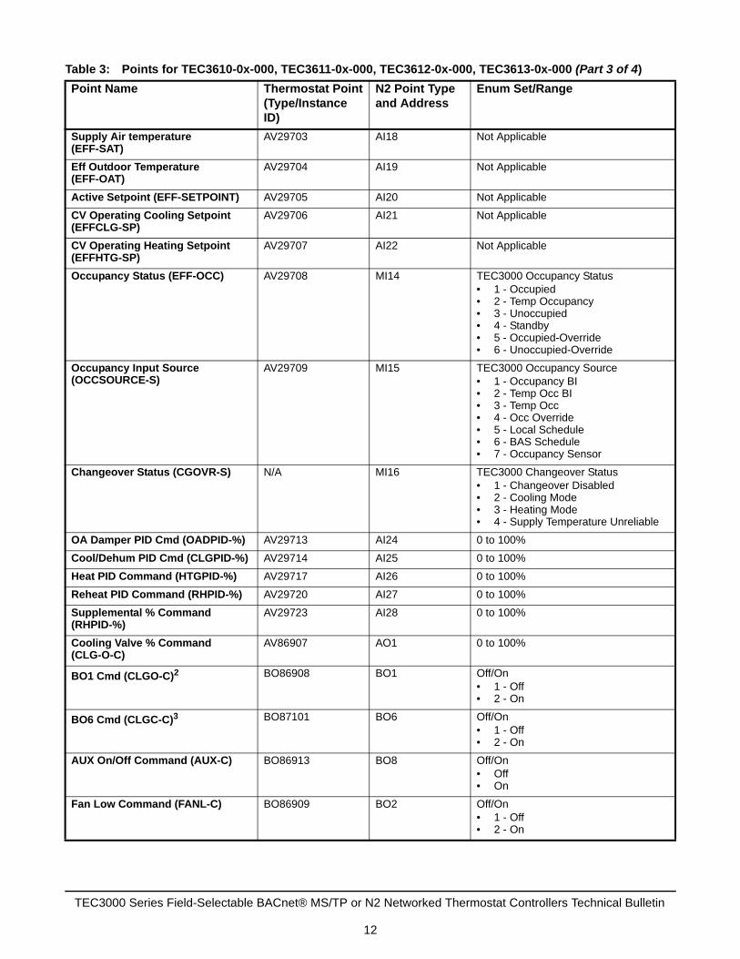
Supply Air temperature(EFF-SAT)
AV29703 AI18 Not Applicable
Eff Outdoor Temperature (EFF-OAT)
AV29704 AI19 Not Applicable
Active Setpoint (EFF-SETPOINT) AV29705 AI20 Not Applicable
CV Operating Cooling Setpoint (EFFCLG-SP)
AV29706 AI21 Not Applicable
CV Operating Heating Setpoint (EFFHTG-SP)
AV29707 AI22 Not Applicable
Occupancy Status (EFF-OCC) AV29708 MI14 TEC3000 Occupancy Status• 1 - Occupied• 2 - Temp Occupancy• 3 - Unoccupied• 4 - Standby• 5 - Occupied-Override• 6 - Unoccupied-Override
Occupancy Input Source (OCCSOURCE-S)
AV29709 MI15 TEC3000 Occupancy Source• 1 - Occupancy BI• 2 - Temp Occ BI• 3 - Temp Occ• 4 - Occ Override• 5 - Local Schedule• 6 - BAS Schedule• 7 - Occupancy Sensor
Changeover Status (CGOVR-S) N/A MI16 TEC3000 Changeover Status• 1 - Changeover Disabled• 2 - Cooling Mode• 3 - Heating Mode• 4 - Supply Temperature Unreliable
OA Damper PID Cmd (OADPID-%) AV29713 AI24 0 to 100%
Cool/Dehum PID Cmd (CLGPID-%) AV29714 AI25 0 to 100%
Heat PID Command (HTGPID-%) AV29717 AI26 0 to 100%
Reheat PID Command (RHPID-%) AV29720 AI27 0 to 100%
Supplemental % Command (RHPID-%)
AV29723 AI28 0 to 100%
Cooling Valve % Command (CLG-O-C)
AV86907 AO1 0 to 100%
BO1 Cmd (CLGO-C)2 BO86908 BO1 Off/On• 1 - Off• 2 - On
BO6 Cmd (CLGC-C)3 BO87101 BO6 Off/On• 1 - Off• 2 - On
AUX On/Off Command (AUX-C) BO86913 BO8 Off/On• Off• On
Fan Low Command (FANL-C) BO86909 BO2 Off/On• 1 - Off• 2 - On
Table 3: Points for TEC3610-0x-000, TEC3611-0x-000, TEC3612-0x-000, TEC3613-0x-000 (Part 3 of 4)
Point Name Thermostat Point(Type/Instance ID)
N2 Point Type and Address
Enum Set/Range
TEC3000 Series Field-Selectable BACnet® MS/TP or N2 Networked Thermostat Controllers Technical Bulletin
12

Load Shed Active (LOADSHED-EN)
MV29724 Not Applicable No/Yes• 1 - No• 2 - Yes
Load Shed Rate limit (LOADSHED-RL)
AV29725 Not Applicable 0 to 1°F (-17.78 to -17.22°C)
Load Shed Adjust (LOADSHED-ADJ)
AV29726 Not Applicable 0 to 8°F (-17.78 to -13.33°C)
Fan Medium Command (FANM-C) BO86910 BO3 Off/On• 1 - Off• 2 - On
Fan High Command (FANH-C) BO86911 BO4 Off/On• 1 - Off• 2 - On
Heating Valve % Command (HTG-O-C)
BO86912 AO2 0 to 100%
BO5 Command (HTGO-C)4 BO87102 BO5 Off/On• 1 - Off• 2 - On
BO7 Command (HTGC-C)5 BO87102 BO7 Off/On• 1 - Off• 2 - On
Fan Speed % Command (FANSPD-%)
AV86905 AO3 0 to 100%
Fan Speed Status (FANSPD-S) MV29712 MI18 Supply Fan Status• 1 - Off• 2 - On• 3 - Low• 4 - Medium• 5 - High
B1 Sensor (BI1-S) BI30827 BI1 Off/On• 1 - Off• 2 - On
B2 Sensor (BI2-S) BI30828 BI2 Off/On• 1 - Off• 2 - On
AO1 Output (VSF-O) AV86809 AO1 0 to 100%
Local Occupancy (LOCAL-OCC) MV6 MI6 Occ Schedule• 1 - Occupied• 2 - Unoccupied• 3 - Standby• 4 - Not Set
Schedule Schedule10133 Not Available Not Applicable
Calendar Calendar10019 Not Available Not Applicable
1. The passcode cannot be changed from BAS. The passcode can only be defined by the local display or through Mobile Access Portal (MAP) version 4.0.
2. This is the output used when wired to the Normally Open (N.O.) terminal.3. This is the output used when wired to the Normally Closed (N.C.) terminal.4. This is the output used when wired to the N.O. terminal.5. This is the output used when wired to the N.C. terminal.
Table 3: Points for TEC3610-0x-000, TEC3611-0x-000, TEC3612-0x-000, TEC3613-0x-000 (Part 4 of 4)
Point Name Thermostat Point(Type/Instance ID)
N2 Point Type and Address
Enum Set/Range
TEC3000 Series Field-Selectable BACnet® MS/TP or N2 Networked Thermostat Controllers Technical Bulletin
13

Table 4: Points for TEC3620-0x-000, TEC3621-0x-000, TEC3622-0x-000, TEC3623-0x-000 (Part 1 of 4)
Point Name Thermostat Point(Type/Instance ID)
N2 Point Type and Address
Enum Set/Range
Control Mode (SYSTEM-MODE) MV29500 MI1 TEC3000 Unit Control Mode• 1 - Auto• 2 - Cooling• 3 - Heating
Unit Enable (UNITEN-MODE) MV29501 MI2 Shutdown/Enable• 1 - Shutdown• 2 - Enable
Occupied Cooling Setpoint (CLGOCC-SP)
AV29502 AO1 60 to 100°F (15 to 38°C)
Occupied Heating Setpoint (HTGOCC-SP)
AV29503 AO2 45 to 85°F (7 to 30°C)
Unoccupied Cooling Setpoint (CLGUNOCC-SP)
AV29504 AO3 60 to 100°F (15 to 38°C)
Unoccupied Heating Setpoint (HTGUNOCC-SP)
AV29505 AO4 45 to 85°F (7 to 30°C)
Standby Cooling Setpoint (CLGSTBY-SP)
AV29506 AO5 60 to 100°F (15 to 38°C)
Standby Heating Setpoint (HTGSTBY-SP)
AV29507 AO6 45 to 85°F (7 to 30°C)
Setpoint Offset (WC-ADJ) AV29508 AO7 0 to Max Setpoint Offset
Hold/Run (HOLDRUN-MD) MV29509 MI3 Hold Run• 1 - Hold• 2 - Run
Humidity Sp (ZNH-SP) AV29510 AI8 0 to 100% RH
Network Override Supply Air Temperature (NET-SAT)
AV29515 AI13 0 to 150°F (-18 to 65°C)
Dry Bulb Sp (DB-SP) AV29511 AI9 40 to 80°F (4 to 27°C)
OA Enthalpy SP (OAENTH-SP) AV29512 AI10 10 to 50 BTU/lb dry air (23 to 116 J/kg)
NetOAT (NET-OAT) AV29513 AI11 -50 to 125°F (-46 to 52°C)
NetOAH (NET-OAH) AV29514 AI12 0 to 100% RH
Reset PID Tuning (TUNING-RESET)
MV29517 MI4 No/Yes• 1 - No• 2 - Yes
Net ZNH (NET-ZNH) AV29516 AI14 0 to 100% RH
Manual Occ (OCCOVRD-MODE) MV29518 MI5 UI Occ Override• 1 - No Override• 2 - Occupied• 3 - Unoccupied
Supervisory Occupancy (NET-OCC) MV29519 MI6 Occ Base Set• 1 - Occupied• 2 - Unoccupied• 3 - Standby
Occupancy Configuration Source (OCC-CONFIG)
MV29520 MI7 SE Occupancy Mode• 1 - Schedule• 2 - External
Passcode (PASSCODE)1 AV29522 AI15 0000 to 9999
TEC3000 Series Field-Selectable BACnet® MS/TP or N2 Networked Thermostat Controllers Technical Bulletin
14

CgOvr Mode (CGOVR-MODE)
MV29523 MI8 TEC3000 Unit Control Mode• 1 - Auto• 2 - Cooling• 3 - Heating
Fan Mode (FAN-MODE) MV29524 MI9 TEC3000 Fan Mode• 1 - On• 2 - Auto• 3 - Smart
Fan Override (FANOVRD-MODE) MV29525 MI10 UI Fan Override• 1 - On• 2 - Auto• 3 - Quiet
Aux Mode (AUX-MODE) MV29527 MI11 TEC3000 Aux Mode• 1 - Not Used• 2 - Occupied NO• 3 - Occupied NC• 4 - Occupied Fan NO• 5 - Occupied Fan NC• 6 - On• 7 - Off
Temperature Units (TEMP-UNITS)
MV29528 MI12 Unit Set• 1 - IP• 2 - SI
Max Setpoint Offset (MAXSP-OFFSET)
AV29529 AI29 0 to 20°F (0 to -11°C)
Unit Status (UNIT-S) MV29700 MI13 TEC3000 Detailed Control Status • 1 - System Fault• 2 - Airflow Fault• 3 - Open Window• 4 - Control Off• 5 - Unreliable Temperature• 6 - Dehumidification• 7 - Idle• 8 - Cooling• 9 - Heating• 10 - Cooling Unavailable• 11 - Heating Unavailable• 12 - Cooling Unavailable due to
Changeover• 13 - Cooling Unavailable due to QA
Temp• 14 - Cooling Unavailable due to
Control Mode• 15 - Heating Unavailable due to
Changeover• 16 - Heating Unavailable due to QA
Temp• 17 - Heating Unavailable due to
Control Mode
Operational Space Temperature (EFF-ZNT)
AV29701 AI16 Not Applicable
Eff Zone Hum (EFF-ZNH) AV29702 AI17 Not Applicable
Supply Air Temperature (EFF-SAT)
AV29703 AI18 Not Applicable
Table 4: Points for TEC3620-0x-000, TEC3621-0x-000, TEC3622-0x-000, TEC3623-0x-000 (Part 2 of 4)
Point Name Thermostat Point(Type/Instance ID)
N2 Point Type and Address
Enum Set/Range
TEC3000 Series Field-Selectable BACnet® MS/TP or N2 Networked Thermostat Controllers Technical Bulletin
15

Eff Outdoor Temperature (EFF-OAT)
AV29704 AI19 Not Applicable
Active Setpoint (EFF-SETPOINT) AV29705 AI20 Not Applicable
CV Operating Cooling Setpoint (EFFCLG-SP)
AV29706 AI21 Not Applicable
CV Operating Heating Setpoint (EFFHTG-SP)
AV29707 AI22 Not Applicable
Occupancy Status (EFF-OCC) AV29708 MI14 TEC3000 Occupancy Status• 1 - Occupied• 2 - Temp Occupancy• 3 - Unoccupied• 4 - Standby• 5 - Occupied-Override• 6 - Unoccupied-Override
Occupancy Input Source (OCCSOURCE-S)
AV29709 MI15 TEC3000 Occupancy Source• 1 - Occupancy BI• 2 - Temp Occ BI• 3 - Temp Occ• 4 - Occ Override• 5 - Local Schedule• 6 - BAS Schedule• 7 - Occupancy Sensor
Changeover Status (CGOVR-S) N/A MI16 TEC3000 Changeover Status• 1 - Changeover Disabled• 2 - Cooling Mode• 3 - Heating Mode• 4 - Supply Temperature Unreliable
OA Damper PID Command (OADPID-%)
AV29713 AI24 0 to 100%
Cool/Dehum PID Command (CLGPID-%)
AV29714 AI25 0 to 100%
Heat PID Command (HTGPID-%) AV29717 AI26 0 to 100%
Reheat PID Command (RHPID-%) AV29720 AI27 0 to 100%
Supplemental % Command (RHPID-%)
AV29723 AI28 0 to 100%
Cooling Valve % Command (CLG-O-C)
AV86907 AO1 0 to 100%
AUX On/Off Command (AUX-C) BO86913 BO8 Off/On• Off• On
Fan Low Command (FANL-C) BO86909 BO2 Off/On• 1 - Off• 2 - On
Fan Medium Command (FANM-C) BO86910 BO3 Off/On• 1 - Off• 2 - On
Fan High Command (FANH-C) BO86911 BO4 Off/On• 1 - Off• 2 - On
Heating Valve % Command (HTG-O-C)
BO86906 AO2 0 to 100%
Table 4: Points for TEC3620-0x-000, TEC3621-0x-000, TEC3622-0x-000, TEC3623-0x-000 (Part 3 of 4)
Point Name Thermostat Point(Type/Instance ID)
N2 Point Type and Address
Enum Set/Range
TEC3000 Series Field-Selectable BACnet® MS/TP or N2 Networked Thermostat Controllers Technical Bulletin
16

Load Shed Active (LOADSHED-EN) MV29724 Not Applicable No/Yes• 1 - No• 2 - Yes
Load Shed Rate limit (LOADSHED-RL)
AV29725 Not Applicable 0 to 1°F (-17.78 to -17.22°C)
Load Shed Adjust (LOADSHED-ADJ)
AV29726 Not Applicable 0 to 8°F (-17.78 to -13.33°C)
Fan Speed % Command (FANSPD-%)
AV86905 AO3 0 to 100%
Fan Speed Status (FANSPD-S) MV29712 MI18 Supply Fan Status• 1 - Off• 2 - On• 3 - Low• 4 - Medium• 5 - High
BI1 Sensor (BI1-S) BI30827 BI1 Off/On• 1 - Off• 2 - On
BI2 Sensor (BI2-S) BI30828 BI2 Off/On• 1 - Off• 2 - On
1. The passcode cannot be changed from BAS. The passcode can only be defined by the local display or through MAP version 4.0.
Table 5: Points for TEC3620-0x-000, TEC3621-0x-000, TEC3622-0x-000, TEC3623-0x-000 (Part 1 of 2)
Point Name Thermostat Point(Type/Instance ID)
N2 Point Type and Address
Enum Set/Range
Fan Cmd (SF-O) MV29711 MO23 Not Applicable
Fan Speed (FANSPD-S) MV29712 MO18 • Off• On• Low• Medium• High
Cool Cmd (CLG-O) AV29714 AO25 Not Applicable
Cool Stg 1 (CLG1-C) MV29715 MO19 • Off• On
Heat Cmd (HTG-O) AV29717 AI26 Not Applicable
Heat Stg 1 (HTG1-C) MV29718 MO21 • Off• On
Reheat Cmd (RH-O) AV29720 AI27 Not Applicable
Reheat (RH-C) MV29721 MO23 • Off• On
Local Occupancy (LOCAL-OCC) MV6 MI6 Occ Schedule• 1 - Occupied• 2 - Unoccupied• 3 - Standby• 4 - Not Set
Schedule Schedule10133 Not Available Not Applicable
Table 4: Points for TEC3620-0x-000, TEC3621-0x-000, TEC3622-0x-000, TEC3623-0x-000 (Part 4 of 4)
Point Name Thermostat Point(Type/Instance ID)
N2 Point Type and Address
Enum Set/Range
TEC3000 Series Field-Selectable BACnet® MS/TP or N2 Networked Thermostat Controllers Technical Bulletin
17

Calendar Calendar10019 Not Available Not Applicable
Table 6: Points for TEC3630-0x-000, TEC3631-0x-000 (Part 1 of 3)
Point Name Thermostat Point(Type/Instance ID)
N2 Point Type and Address
Enum Set/Range
Unit Status (UNIT-S) MV29700 MO13 • System Fault• Airflow Fault• Open Window• Control Off• Unreliable Temperature• Dehumidification• Idle• Cooling• Heating• Cooling Unavailable• Heating Unavailable• Cooling Unavailable due to
Changeover• Cooling Unavailable due to QA
Temp• Cooling Unavailable due to
Control Mode• Heating Unavailable due to
Changeover• Heating Unavailable due to QA
Temp• Heating Unavailable due to
Control Mode
Operational Space Temperature (EFF-ZNT)
AV29701 AO16 Not Applicable
Zone Hum (EFF-ZNH) AV29702 AO17 Not Applicable
Supply Air Temperature (EFF-SAT)
AV29703 AO18 Not Applicable
Outdoor Air Temperature (EFF-OAT)
AV29531 AO16 Not Applicable
Active Setpoint (EFF-SETPOINT) AV29705 AO20 Not Applicable
CV Operating Cooling Setpoint (EFFCLG-SP)
AV29706 AO21 Not Applicable
CV Operating Heating Setpoint (EFFHTG-SP)
AV29707 AO22 Not Applicable
Occupancy Status (EFF-OCC) MV29708 MO14 • Occupied• Temp Occupancy• Unoccupied• Standby• Occupied-Override• Unoccupied-Override
Table 5: Points for TEC3620-0x-000, TEC3621-0x-000, TEC3622-0x-000, TEC3623-0x-000 (Part 2 of 2)
Point Name Thermostat Point(Type/Instance ID)
N2 Point Type and Address
Enum Set/Range
TEC3000 Series Field-Selectable BACnet® MS/TP or N2 Networked Thermostat Controllers Technical Bulletin
18

Occupancy Input Source (OCCSOURCE-S)
MV29709 MO15 • Occupancy B1• Temp Occ B1• Temp Occ• Occ Override• Local Schedule• BAS Schedule• Occupancy Sensor
Econ Command (OAD-O) AV29713 AO24 Not Applicable
Cool Cmd (CLG-O) AV29714 AO25 Not Applicable
Cool Stg 1 (CLG1-C) MV29715 MO19 • Off• On
Cool Stg 2 (CLG2-C) MV29716 MO20 • Off• On
Heat Cmd (HTG-O) AV29717 AI26 Not Applicable
Heat Stg 1 (HTG1-C) MV29718 MO21 • Off• On
Heat Stg 2 (HTG2-C) MV29719 MO22 • Off• On
Supp Command (SUPHTG-C) MV29722 MO24 • Off• On
Supp Heating (SUPHTG-O) AV29723 AI28 Not Applicable
Manual Occ (OCCOVRD-MODE) MV29518 MI5 UI Occ Override• 1 - No Override• 2 - Occupied• 3 - Unoccupied
Supervisory Occupancy (NET-OCC) MV29519 MI6 Occ Base Set• 1 - Occupied• 2 - Unoccupied• 3 - Standby
Occupancy Configuration Source (OCC-CONFIG)
MV29520 MI7 SE Occupancy Mode• 1 - Schedule• 2 - External
Passcode (PASSCODE)1 AV29522 AI15 0000 to 9999
CgOvr Mode (CGOVR-MODE)
MV29523 MI8 TEC3000 Unit Control Mode• 1 - Auto• 2 - Cooling• 3 - Heating
Fan Mode (FAN-MODE) MV29524 MI9 TEC3000 Fan Mode• 1 - On• 2 - Auto• 3 - Smart
Fan Override (FANOVRD-MODE) MV29525 MI10 UI Fan Override• 1 - On• 2 - Auto• 3 - Quiet
Table 6: Points for TEC3630-0x-000, TEC3631-0x-000 (Part 2 of 3)
Point Name Thermostat Point(Type/Instance ID)
N2 Point Type and Address
Enum Set/Range
TEC3000 Series Field-Selectable BACnet® MS/TP or N2 Networked Thermostat Controllers Technical Bulletin
19

Aux Mode (AUX-MODE) MV29527 MI11 TEC3000 Aux Mode• 1 - Not Used• 2 - Occupied NO• 3 - Occupied NC• 4 - Occupied Fan NO• 5 - Occupied Fan NC• 6 - On• 7 - Off
Temperature Units (TEMP-UNITS)
MV29528 MI12 Unit Set• 1 - IP• 2 - SI
Max Setpoint Offset (MAXSP-OFFSET)
AV29529 AI29 0 to 20°F (0 to -11°C)
B1 Sensor (BI1-S) BI30827 BI1 Off/On• 1 - Off• 2 - On
B2 Sensor (BI2-S) BI30828 BI2 Off/On• 1 - Off• 2 - On
Load Shed Active (LOADSHED-EN) MV29724 Not Applicable No/Yes• 1 - No• 2 - Yes
Load Shed Rate limit (LOADSHED-RL)
AV29725 Not Applicable 0 to 1°F (-17.78 to -17.22°C)
Load Shed Adjust (LOADSHED-ADJ)
AV29726 Not Applicable 0 to 8°F (-17.78 to -13.33°C)
Local Occupancy (LOCAL-OCC) MV6 MI6 Occ Schedule• 1 - Occupied• 2 - Unoccupied• 3 - Standby• 4 - Not Set
Schedule Schedule10133 Not Available Not Applicable
Calendar Calendar10019 Not Available Not Applicable
1. The passcode cannot be changed from BAS. The passcode can only be defined by the local display or through MAP version 4.0.
Table 7: Multi-State Event Points for TEC361x-0x-000, TEC362x-0x-000, TEC363x-0x-000 (BACnet MS/TP Only) (Part 1 of 2)
Point Name Thermostat Point(Type/Instance ID)
Supported Events
MV Critical Active EventCritical Active Event NTFMV Critical Inactive EventCritical Inactive Event NTF
MV30000Notification 10MV29999Notification 11
• Board Mismatch• Controller Fault• Display Failure• Zone Temp Unreliable• Open Window• Fan Lock• Zone Temperature Too Cold• Zone Temperature Too Hot• Supply Fan Fault
Table 6: Points for TEC3630-0x-000, TEC3631-0x-000 (Part 3 of 3)
Point Name Thermostat Point(Type/Instance ID)
N2 Point Type and Address
Enum Set/Range
TEC3000 Series Field-Selectable BACnet® MS/TP or N2 Networked Thermostat Controllers Technical Bulletin
20

Event reporting of the Fault Status for each of the above Multistate Value Objects is configured through its corresponding Notification object (for example, MV Critical Active Event corresponds to Critical Active Event NTF). The Active MV objects are set up to send Off Normal events while the Inactive MV objects are set up to send Normal events. These events and their routing by the Notification object are pre-configured to go to the FC bus supervisor. The Ack Required setting should be checked when pop-up alarms are desired on the NAE. For additional details on this object, refer to the Notification Class/BACnet Notification Class chapter of the Metasys® Common Object (LIT-694020).
MV Service Priority Active EventService Priority Active Event NTFMV Service Priority Inactive EventService Priority Inactive Event NTF
MV29998Notification 12MV29997Notification 13
• Heating Ineffective• Cooling Ineffective• Supply Fan Runtime Exceeded
MV Service Active EventService Active Event NTFMV Service Inactive EventService Inactive Event NTF
MV29996Notification 14MV29995Notification 15
• Calibration Corrupt• USB Malfunction• Remote Zone Temp Fail• Supply Temp Fail• Outdoor Temp Fail• Internal Sensor Fail• OA Lockouts Disabled• Econ Unavailable• Dehum Unavailable• Service• Dirty Filter• Changeover Fail
Table 7: Multi-State Event Points for TEC361x-0x-000, TEC362x-0x-000, TEC363x-0x-000 (BACnet MS/TP Only) (Part 2 of 2)
Point Name Thermostat Point(Type/Instance ID)
Supported Events
TEC3000 Series Field-Selectable BACnet® MS/TP or N2 Networked Thermostat Controllers Technical Bulletin
21

SchedulingThe TEC3000 Series Thermostat Controller can operate as a standalone unit with an internal schedule or scheduled with an external schedule. The OCC-CONFIG object sets the method that is used for scheduling.
If the OCC-CONFIG is set to External, the NET-OCC object is used to control the unit externally.
If the OCC-CONFIG is set to Schedule, the internal schedule commands the LOCAL-OCC object, which sets the Occupancy Schedule command.
Note: If you do not have a schedule in the Schedule object and you have the OCC-CONFIG set to Schedule, you can control the unit with the LOCAL-OCC object externally; however, we do not recommend this method. See Table 8 for scheduling information.
Once the Occupancy Schedule command is set the effective occupancy is determined by settings shown in the Occupancy Determination table. See Table 9.
Table 8: BAS Objects for Scheduling
BAS Objects for Scheduling
OCC-CONFIG LOCAL-OCC (Commanded by Internal Schedule)
NET-OCC Occupancy Schedule
Command1
1. The effective occupancy can be affected by other factors listed in Table 9.
External Any State(Internal Schedule in Control)
Occupied Occupied
Unoccupied Unoccupied
Standby Standby
Not Set Not Set
Schedule Occupied Any State(Internal Schedule in Control)
Occupied
Unoccupied Unoccupied
Standby Standby
Not Set Not Set
TEC3000 Series Field-Selectable BACnet® MS/TP or N2 Networked Thermostat Controllers Technical Bulletin
22

e of
e
S)
r
et
r
Table 9: Occupancy Determination
Sequence of Operation (Highest to Lowest Priority)
Occupancy Override Mode (OCCOVRD-MODE)
Occupancy BI (BI1-S,
BI2-S)1
1. Not Configured means that neither BI1 Config nor BI2 Config is set to Occupancy BI. Open and Closed refer to the current statthe BI when configured as Occupancy.
Temporary
Occupancy2, 3
2. True is triggered by interacting with the screen during a scheduled unoccupied period. A value of True can only occur when thschedule is not Occupied.
3. When triggered by a BI configured for Temp Occ, the input is ignored when the schedule is Occupied, the Manual OccupancyMode is NOT No Override, or an Occupancy BI is configured.
Occupancy Schedule (External or Schedule) (OCC-CONFIG, NET-OCC)
Motion
Sensor4
4. Built-in occupancy sensing (PIR) or EI configured for Motion NO or Motion NC.
Effective Occupancy (EFF-OCC)
Occupancy Source (OCCSOURCE-
Occupied – – – – Occupied-Override
Occ Override
Unoccupied Unoccupied-Override
No Override Closed1 Occupied Occupancy BI
Open1 Unoccupied
Not Configured1
True2 NOT Occupied Temp Occupancy
Temp Occ
True3 NOT Occupied Temp Occupancy
Temp Occ BI
False Occupied True Occupied Occupancy Senso
False Standby
Disabled Occupied Occupancy ScheduleUnoccupied – Unoccupied
Standby Standby
Not Set5
5. Not Set occurs when no events are scheduled through the local scheduler, or the schedule source is set to Schedule and theSchedule is writing Not Set as the schedule.
Commanding Objects from a Supervisory ControllerFrom an NAE, analog and multistate value objects are commanded by using the Change Default command. The lastcommand that does not use priority, that is received by the controller, is executed. When implementing commands tothese value objects in other features, the default should be used. Commands to hardware objects support the same sthat you use for the NAE.
True Occupied Occupancy Senso
False Unoccupied
Disabled Occupied Occupancy Schedule
TEC3000 Series Field-Selectable BACnet® MS/TP or N2 Networked Thermostat Controllers Technical Bulletin
23

Menu and Submenu DescriptionsThe following sections describe the menu and submenus for the TEC3000 Series Thermostat Controller. Refer to the TEC3000 Series Proportional Fan Coil and Zoning Thermostat Controllers with Dehumidification Capability Installation Instructions (Part No. 24-10788-0), TEC3000 Series On/Off or Floating Fan Coil and Zoning Thermostat Controllers with Dehumidification Capability Installation Instructions (Part No. 24-10787-6), or TEC3000 Series Single- or Two-Stage Economizer Thermostat Controllers Installation Instructions (Part No. 24-10789-5) for more information based on your thermostat model.
SetpointsA fixed differential of 2°F exists between heating and cooling setpoints for occupied, unoccupied, and standby modes. If a setpoint is set within 2 degrees of the corresponding setpoint, the controller automatically adjusts the corresponding setpoint to be 2 degrees away from the manually adjusted setpoint.
Occupied Cooling - setpoint that the controller holds the zone at when cooling is needed in the Occupied state
Occupied Heating - setpoint that the controller holds the zone at when heating is needed in the Occupied state
Unoccupied Cooling - setpoint that the controller holds the zone at when cooling is needed in the Unoccupied state
Unoccupied Heating - setpoint that the controller holds the zone at when heating is needed in the Unoccupied state
Standby Cooling - setpoint that the controller holds the zone at when cooling is needed in the Standby state
Standby Heating - setpoint that the controller holds the zone at when heating is needed in the Standby state
Dehumidification - This is the setpoint that the controller maintains by operating dehumidification control when the zone humidity rises above it. This option is only available on 2-pipe fan coil units or 4-pipe fan coil units with reheat, and is only shown when Dehumidification Enable is set to True under the Control Setup menu.
Warmer Cooler Adjustment - degree amount that is added to the current Setpoint that results in the Effective Setpoint
Maximum Setpoint Offset - maximum value for the Warmer Cooler Adjustment
Effective Zone Temperature - zone temperature used for control after determining if it is the onboard or remote zone temperature sensor being used
Effective Zone Humidity - zone humidity used for control
Effective Setpoint - setpoint used for control that results from the combination of the occupancy and control mode parameters
Effective Cooling Setpoint - cooling setpoint that results from the combination of the occupancy and control mode parameters
Effective Heating Setpoint - heating setpoint that results from the combination of the occupancy and control mode parameters
Network Supply Air Temperature - supply air temperature provided by the bus supervisory controller
Effective Supply Air Temperature - supply air temperature that results from a combination of the local SAT sensor and the NET-SAT value
TEC3000 Series Field-Selectable BACnet® MS/TP or N2 Networked Thermostat Controllers Technical Bulletin
24

Schedule OptionsOptimal Start Enable - This enables or disables the Optimal Start algorithm to automatically start the equipment prior to the scheduled occupancy period in order to reach the occupied setpoint at the same time the schedule transitions from Unoccupied to Occupied. Setting this option to Yes only has an effect when the local schedule is used.
The Optimal Start feature provides preconditioning of a zone ahead of a scheduled change to its occupancy mode. The feature uses schedule times of the Local Occupancy object to determine when it is the proper time to command equipment based on the next occupancy mode changes. The most energy savings is derived by operating on the earliest change to occupancy as well the latest change to unoccupied.
Calendar Object - The schedule and calendar object work together to determine the type of schedule that is in effect. It is recommended for the TEC that only weekly schedules are used.
Temp Occ Duration - This is the length for which the controller remains in a temporary occupancy period when triggered during an unoccupied period. Temporary occupancy is triggered by interacting with the touch screen while unoccupied or by activating a binary input configured for temporary occupancy.
Motion Sensor Timeout - This sets how long the controller waits to return to Standby mode after the last detection of motion while in a scheduled Occupied period. Setting the timeout to 0 minutes disables standby mode.
Manual Occupancy Mode - This allows you to override all schedules and other sources of occupancy and put the controller indefinitely into an Occupied or Unoccupied state.
Schedule Source - This sets the source of the occupancy schedule on the TEC. Setting to Schedule (Local) utilizes the internal 7-day programmable schedule, and setting to External (BAS) uses the command from a building automation system if the BAS is online. If the BAS is offline, the schedule reverts to the onboard schedule.
Display SettingsPasscode Enabled - By setting this to True enables a 4-digit passcode to enter the configuration menu. The TEC prompts you for the passcode upon saving this setting to True. Passcodes can only be defined on the local display.
Brightness Setting - sets the brightness of the display when you are interacting with the display
Enable Backlight Timeout - sets whether the backlight should timeout and go to low brightness after 3 minutes
Units - sets Imperial (IP) or Metric (M) units on the display and exposed to a BAS
Time - sets the time on the controller
Time Zone - sets the time zone where the controller is installed
Set Time Format - sets the display time format on the controller
Date - sets the date on the controller
Set Date Format - sets the display date format on the controller
Show Fan Icon On Home - This sets whether the user fan override option is available on the home screen. This option allows you to select the following fan mode overrides from the home screen:
• On - This turns and keeps the fan on. This option overrides shutdown requests, with the exception of Airflow Fault shutdowns.
• Auto - follows the Fan Mode set under the General Settings menu
• Quiet - This follows the Fan Mode set under the General Settings menu, but keeps multi-speed and variable-speed fans at their lowest speeds. This option is no different from Auto for single-speed fans.
Show Temp On Home - sets whether the current zone temperature is displayed on the home screen
Show Humidity On Home - This sets whether the current zone humidity is displayed on the home screen. Humidity is always displayed when the setting is enabled on a thermostat controller with a built-in humidity sensor. The humidity is displayed when a network override is active on thermostat controllers without a built-in humidity sensor.
Show Off Button On Home - sets whether the master control On/Off icon is displayed on the home screen
TEC3000 Series Field-Selectable BACnet® MS/TP or N2 Networked Thermostat Controllers Technical Bulletin
25

Show Hold Button - sets whether the Hold/Run icon is displayed on the home screen
Show Setpoint On Home – sets whether the current zone temperature setpoint is displayed on the home screen
Show Alarms On Home - sets whether the current alarm symbol is displayed on the home screen when warnings or alarms are active
Show Occ Status - sets whether the current occupancy status shows on the home screen
Show Unit Status - sets whether the operational status of the controller shows on the home screen
Show Date/Time - sets whether the date and time show on the home screen
Control Setup
General
Control Mode - sets the thermostat to operate only in Cooling or Heating modes, or to automatically switch between cooling and heating based on the zone temperature
Unit Enable - This enables or disables the control. This option is linked to the Off/On icon on the home screen. The home screen fan override can still turn the fan on when Unit Enable = False
Fan Mode - This sets the operational mode of the fan. The options include:
• On - The fan runs continuously unless control is disabled
• Auto - (M1 and M2) The fan cycles with heating or cooling demand in the zone. (M3) The fan cycles with the equipment stages.
• Smart - The fan operates continuously while occupied, and follows the Auto behavior when unoccupied
Note: The Fan Mode can be overridden by the fan button on the Home screen. Refer to the TEC3000 Series Proportional Fan Coil and Zoning Thermostat Controllers with Dehumidification Capability Installation Instructions (Part No. 24-10788-0), TEC3000 Series On/Off or Floating Fan Coil and Zoning Thermostat Controllers with Dehumidification Capability Installation Instructions (Part No. 24-10787-6), or TEC3000 Series Single- or Two-Stage Economizer Thermostat Controllers Installation Instructions (Part No. 24-10789-5) for more information on the Fan mode.
Max Setpoint Offset - sets the maximum deviation above or below the active programmed setpoint that the user can set from the home screen
Fan On Delay - sets how long the fan waits to turn on after turning on a stage of heating or cooling
Fan Off Delay - sets how long the fan waits to turn off after turning off the last stage of heating or cooling
Frost Protection - allows the controller to turn on heating when the zone temperature drops below 42 degrees Fahrenheit, regardless of whether the control is enabled
Reset PID Tuning - resets the PRAC+ tuning parameters of the PID controllers to the factory defaults
Auto Tuning Enable - enables the PRAC+ auto tuning algorithm to adjust PID tuning parameters for optimal control performance
Dehum Enable - enables dehumidification control when the zone humidity rises above the humidity setpoint
Aux Mode - This sets the mode that the Auxiliary output runs in. The auxiliary port is reserved for Reheat control on Fan Coil and VAV units with reheat enabled. The options include:
• Not Used - opens the contact
• Occupied NO - closes the contact when the controller is occupied
• Occupied NC - opens the contact when the controller is occupied
• Occupied Fan NO - closes the contact when the controller is occupied and the fan is running
• Occupied Fan NC - opens the contact when the controller is occupied and the fan is running
• Off - opens the contact
• On - closes the contact
TEC3000 Series Field-Selectable BACnet® MS/TP or N2 Networked Thermostat Controllers Technical Bulletin
26

Load Shed Rate Limit - sets that rate at which the operating setpoint increases when cooling or decreases when heating after a load shed command is issued
Load Shed Adjust - limit at when the operating setpoint increases when cooling or decreases when heating after a load shed command is issued
Fan Alarm Delay - This is the amount of time that the Fan Status Input has to verify that the fan is on. If the fan operation is not verified within the specified timeframe, the TEC3000 issues an alarm. You must also define BI1 or BI2 as a Supply Fan Status using the BI1 or BI2 Config setting.
Fan Alarm Action - This sets the thermostats reaction to the fan alarm. Shutdown turns the unit off until the fan alarm reset is triggered. Enable keeps the unit operating.
Fan Alarm Reset - turns the unit on if it was turned off by a fan alarm
Supply Temp Alarm Enable - This enables the supply temperature alarm diagnostics. An alarm is issued when the supply air temperature does not drop a set number of degrees within a set number of minutes after a cooling command is issued. An alarm is issued when the supply air temperature does not rise a set number of degrees within a set number of minutes after a heating command is issued.
Inputs
BI1 Config - sets the mode that the first binary input operates in
BI2 Config - sets the mode that the first binary input operates in
Supply Temp Type - This sets the type of supply temperature detection being used for changeover. The options include:
• Analog Sensor - a thermistor is connected to the COS input
• Heating Closed Switch - a switch that closes above a certain temperature is connected to the COS input
• Cooling Closed Switch - a switch that opens above a certain temperature is connected to the COS input
Supply Temp Sensor - sets the type of analog supply temperature sensor connected to the controller
Supply Temp Offset - sets the offset applied to the supply/discharge temperature reading
Zone Temp Sensor - sets the type of analog zone temperature sensor connected to the controller
Zone Temp Offset - sets the offset applied to the zone temperature displayed on the screen and used for control
Outdoor Temp Sensor - sets the type of analog outdoor air temperature sensor connected to the controller
Outdoor Temp Offset - sets the offset applied to the outdoor temperature reading
Humidity Offset - sets the offset applied to the zone humidity displayed on the home screen and used for control
Reset Sensors - This resets sensor inputs back to factory state. This clears alarms for sensors which were connected at one point and are no longer connected.
Zone Temp Alarm Enabled - enables high and low temperature alarms
Zone Temp Low Limit - sets the low alarm limit
Zone Temp High limit - sets the high alarm limit
Network SetupFC Comm Mode - sets BACnet MS/TP or N2 communications mode
BACnet Instance ID - sets the instance ID of the controller when on a BACnet MS/TP network
N2 Address - sets the physical network address on an N2 network
BACnet Address - sets the physical network address on a BACnet MS/TP network
MS/TP Baud Rate - sets the baud rate of the BACnet MS/TP network
BACnet Encoding Type - sets the encoding type to use on the BACnet MS/TP network
TEC3000 Series Field-Selectable BACnet® MS/TP or N2 Networked Thermostat Controllers Technical Bulletin
27

Equipment Setup
General
Unit Type - sets the type of fan coil or VAV system being controlled
Htg/Clg Device Type - sets the output type to Floating (Incremental) or On-Off (2-position)
Actuator Stroke Time - sets the stroke time for a floating (Incremental) actuator to open or close
Number of Compressors - sets the number of compressors in a rooftop unit or heat pump
Runtime Equalization - When enabled, the controller alternates between Y1 and Y2 calls when cycling 2-stage compressors to ensure both compressors are equally used.
Number of Heating Stages - This sets the number of heat stages in a rooftop unit. This option does not exist on heat pumps. Heat Pumps support a single stage of supplemental heating on top of compressor heating.
Compressor Min On Time - sets the minimum time that a compressor runs under normal control conditions
Compressor Min Off Time - sets the minimum time that a compressor must be off for before turning on again
Cooling Min On Time - sets the minimum time that the cooling valve is open under normal control conditions
Cooling Min Off Time - sets the minimum time that the cooling valve is closed before opening again
Heating Min On Time - sets the minimum time that the heating valve/stage is open under normal conditions
Heating Min Off Time - sets the minimum time that the heating valve/stage is closed before opening again
Reheat Min On Time - sets the minimum time that the reheat device runs under normal conditions
Reheat Min Off Time - sets the minimum time that the reheat device is off before starting again
Supp Min On Time - sets the minimum time that the supplemental heating runs under normal conditions
Supp Min Off Time - sets the minimum time that the supplemental heating is off before starting again
Cooling Lockout Temp - sets the outdoor temperature below which cooling does not run regardless of zone temperature
Heating Lockout Temp - sets the outdoor temperature above which heating does not run regardless of zone temperature (note: Frost Protection overrides this lockout)
Valve Open Voltage - sets the voltage at which the heating/cooling valve is fully opened
Valve Closed Voltage - sets the voltage at which the heating/cooling valve is fully closed
Supply Fan
Supply Fan Type - sets the type of fan to Single-, Multi- or Variable-Speed
Start Voltage - sets the voltage at which the variable speed fan starts running
Full Speed Voltage - sets the voltage at which the variable speed fan reaches its full speed
Minimum Command - sets the minimum command (in units of percent of full speed) at which the variable speed fan runs when the controller runs the fan
Medium Speed On Cmd - sets the load percentage at which the multi-speed fan switches to medium speed. Recommended settings are 33 for three-speed fans and 50 for two-speed fans
High Speed On Cmd - This sets the load percentage at which the multi-speed fan switches to high speed. Recommended settings are 66 for three-speed fans and 100 for two-speed fans. Setting to 100% disables the third speed.
Reheat
Reheat Installed - sets if a staged reheat device is installed on the unit
Reheat Min Damper Pos - This sets the minimum VAV damper position when reheat is active. This is used to ensure airflow across a box-mounted reheat device.
TEC3000 Series Field-Selectable BACnet® MS/TP or N2 Networked Thermostat Controllers Technical Bulletin
28
Reheat Fan Required - This sets whether the fan must be running whenever reheat is active. Typically this would be True for box-mounted reheat devices and False for baseboard reheat devices.
Economizer
Economizer Installed - sets if economizer damper control is required on the rooftop or heat pump unit
Minimum Position - sets the minimum economizer position when the fan is running
Closed Voltage - sets the voltage corresponding to the damper being fully shut
Opened Voltage - sets the voltage corresponding to the damper being fully opened
Dry Bulb Setpoint - sets the outdoor air temperature above which economizer cooling does not operate when in dry bulb mode (when the TEC only has outdoor and zone temperature)
Outdoor Enthalpy Setpoint - sets the outdoor air enthalpy above which economizer cooling does not operate when in single enthalpy mode (when the TEC has outdoor temperature, outdoor humidity and zone temperature)
Heat Pump
Heat Pump Supported - This is set if the W1 output should be used to control a reversing valve (O/B) and if Y1/Y2 should control compressors for both cooling and heating. Supp Heating Installed – Sets if a stage of supplemental heating is connected to the W2 output. Many heat pumps with integrated control units use traditional thermostat controller wiring (Y, W, and G inputs). Only set this option to Yes on the heat pump units where the thermostat controller controls an O/B input on the equipment.
Supp Heating Installed - sets if supplemental heating is installed on the unit
Comp Low Lockout Temp - sets the temperature below which compressor heating does not run
Supp High OA Lockout Temp - sets the temperature above which supplemental heating does not run
Reversing Valve Polarity - sets if the reversing valve is cooling when the output is active (Active Cooling) or heating (Active Heating)
Changeover
Changeover Mode - This sets the changeover mode of the unit to Heating, Cooling or Auto. Automatic changeover requires a supply temperature sensor/switch to be installed. When set to Heating or Cooling, the COS input defaults to the analog sensor mode, and is set to be used as an optional temperature monitoring point. Changeover is available only when the unit type is two-pipe or VAV.
Supply Temp Type - This sets the type of supply temperature detection being used for changeover. The options include:
• Analog Sensor - a temperature sensor connected to the COS input
• Heating Closed Switch - a switch which closes above a certain temperature is connected to the COS input
• Cooling Closed Switch - a switch which opens above a certain temperature is connected to the COS input
Changeover Setpoint - This sets the temperature at which the TEC switches from cooling to heating mode. The TEC enters cooling below this setpoint, and once in cooling mode, does not switch back to heating mode until the temperature rises more than 10 degrees above the setpoint.
Supply Temp Sensor - sets the type of analog supply temperature sensor connected to the controller
Supply Temp Offset - sets the offset applied to the supply/discharge temperature reading
System Status
Occupancy Source - displays the current source of the TEC controller’s occupancy
Unit Status - displays if the controller is cooling, heating, idle, disabled, or the reason why cooling and heating is unavailable
Outdoor Air Temperature - displays the outdoor air temperature value in the controller
Supply Air Temperature - displays the supply temperature value in the controller
TEC3000 Series Field-Selectable BACnet® MS/TP or N2 Networked Thermostat Controllers Technical Bulletin
29

Economizer Available - displays the status if the outdoor conditions are suitable for economizer cooling
Cooling OAT Lockout - displays if cooling is being locked out due to low outdoor air temperature
Heating OAT Lockout - displays if heating is being locked out due to high outdoor air temperature
Comp Low OAT Lockout - displays if compressor heating is locked out due to low outdoor air temperature
Supp High Lockout Temp - displays if supplemental heating is locked out due to high outdoor air temperature
Changeover State - displays the current state of changeover detection
Zone Temp Source - displays the source of the zone temperature reading in the TEC controller
Control Status
Cooling % Command - displays the current PID controller percent command
Heating % Command - displays the current PID controller percent command
Reheat % Command - displays the current PID controller percent command
Supplemental % Command - displays the current PID controller percent command
Economizer % Command - displays the current PID controller percent command
Cool Stage 1 - displays if the first stage of cooling is on
Cool Stage 2 - displays if the second stage of cooling is on
Heat Stage 1 - displays if the first stage of heating is on
Heat Stage 2 - displays if the second stage of heating is on
Reheat - displays if the reheat stage is on
Supplemental Heat - displays if the supplemental heat stage is on
Fan % Command - displays the current fan percent command
Fan - displays the current fan status/speed
Trends
Effective Zone Temperature - data sample taken every 15 minutes (100 samples stored)
Active Setpoint - data sample taken every 15 minutes (100 samples stored)
Humidity (If active) - data sample taken every 15 minutes (100 samples stored)
BI1 Status - data sample taken after each use (25 samples stored)
BI2 Status - data sample taken after each use (25 samples stored)
Operational Outdoor Air Temperature (if active) - data sample taken every 15 minutes (100 samples stored)
Supply Air Temperature (if active) - data sample taken every 15 minutes (100 samples stored)
Fan Command - data sample stored after each change (25 samples stored)
Cool Stage 1 On - data sample stored after each change (25 samples stored)
Cool Stage 2 On - data sample stored after each change (25 samples stored)
Heat Stage 1 On - data sample stored after each change (25 samples stored)
Heat Stage 2 On - data sample stored after each change (25 samples stored)
Economizer PID CMD - This is the Economizer output % command. The data sample is taken every 15 minutes (100 samples stored).
Heat PID CMD - This is the Heating Loop % command. The data sample is taken every 15 minutes (100 samples stored).
Cool/Dehumid PID CMD - This is the Cooling and Dehumidification % command. The data sample is taken every 15 minutes (100 samples stored).
TEC3000 Series Field-Selectable BACnet® MS/TP or N2 Networked Thermostat Controllers Technical Bulletin
30

Controller Info
Model Name - displays the TEC factor model name
Software Version - displays the software version that is currently installed
Unit Name - displays the TEC unit name
Description - This is the description of the device. The description is displayed in the Device List for the mobile access portal (MAP), the device list for the wireless network coordinator.
Device Name - This is the description of the device. The description is displayed in the Device List for the MAP, the device list for the wireless network coordinator.
Commissioning
Commissioning - This starts the commissioning mode. Commissioning mode is used to verify hardware inputs and outputs.
Update
View Version - displays the software version that is currently installed
Load Firmware - This allows you to upgrade the TEC firmware if there is a USB drive with an update connected to the TEC. The control is off following the TEC thermostat controller restart after the upgrade.
The configuration can be backed up to the USB drive and restored to like models in order to expedite the commissioning process.
Restore - restores the configuration from either the internal memory or a USB drive
Backup - backs up the current configuration to internal memory and a USB drive (when connected)
IMPORTANT: The control mode is set to Control Off following the TEC thermostat controller restart after a firmware update.
TEC3000 Series Field-Selectable BACnet® MS/TP or N2 Networked Thermostat Controllers Technical Bulletin
31

Troubleshooting Table 10: Fault List (Part 1 of 3)
Faults Probable Causes Solutions
Remote Zone Temp Fail The External Zone Temperature sensor has been disconnected or has failed.
1. Check the wiring of the sensor.2. If intentionally disconnected, reset the
sensors through the Inputs menu under Control Setup.
3. If problems persist, order replacement units and return the affected devices to Johnson Controls under the RMA program.
Supply Temp Fail The External Supply Temperature sensor has been disconnected or has failed.
1. Check the wiring of the sensor.2. If intentionally disconnected, reset sensors
through the menu.3. If problems persist, order replacement units
and return the affected devices to Johnson Controls under the RMA program.
Outdoor Temp Fail The External Outdoor Air Temperature sensor has been disconnected or has failed.
1. Check the wiring of sensor.2. If intentionally disconnected, reset sensors
through the menu.3. If problems persist, order replacement units
and return the affected devices to Johnson Controls under the RMA program.
Internal Sensor Fail An internal sensor has failed on the TEC.
If problems persist, order replacement units and return the affected devices to Johnson Controls under the RMA program.
OA Lockouts Disabled The Local Outdoor Air Temperature sensor has become disconnected or failed or a network Outdoor Air Temperature sensor has timed out, and the TEC is no longer shutting down equipment based on the OA lockout setpoints.
1. If the source of outdoor air temperature was a locally connected sensor, follow the steps for the Outdoor Temp Fail alarm.
2. If the source of outdoor air temperature was a BAS, check the BAS to ensure that it is still online and providing the TEC with the temperature reading. If removal of the BAS mapping was intentional, reset sensors through the menu.
Econ Unavailable The Outdoor Air Temperature sensor is not installed, has failed, or has been disconnected and the TEC can no longer control the economizer.
1. Check the wiring of sensor.2. If intentionally disconnected, reset sensors
through the menu.3. If problems persist, order replacement units
and return the affected devices to Johnson Controls under the RMA program.
Dehum Unavailable Dehumidification is unavailable because the zone humidity sensor has failed.
If problems persist, order replacement units and return the affected devices to Johnson Controls under the RMA program.
Service Equipment connected to the BI configured for a Service alarm is triggering the alarm.
Service the equipment per the manufacturer's recommendation.
Dirty Filter Equipment connected to the BI configured for a Dirty Filter alarm is triggering the alarm.
Replace the filter in the equipment per the manufacturer's instructions.
Calibration Corrupt Factory calibration data is lost or is not installed.
If problems persist, order replacement units and return the affected devices to Johnson Controls under the RMA program.
TEC3000 Series Field-Selectable BACnet® MS/TP or N2 Networked Thermostat Controllers Technical Bulletin
32

Changeover Fail The Supply Temperature Sensor is not installed, has failed, or has been disconnected and the TEC can no longer detect changeover mode to cool or heat.
1. Check the wiring of the sensor.2. If intentionally disconnected, reset sensors
through the menu.3. If problems persist, order replacement units
and return the affected devices to Johnson Controls under the RMA program.
Zone Temp Unreliable All sources of zone temperature are unreliable, including the onboard sensor.
If problems persist, order replacement units and return the affected devices to Johnson Controls under the RMA program.
Open Window The switch connected to the BI configured for Open Window is sensing that the window is opened, and control has shut down.
1. Close the window to resume control.2. Check sensor functionality with an ohmmeter,
and verify the wiring to the TEC.3. If problems persist, order replacement units
and return the affected devices to Johnson Controls under the RMA program.
Fan Lock The switch connected to the BI configured for Fan Lock did not sense airflow within 10 seconds of starting the fan, and control has been shut down.
1. Inspect equipment to ensure fan functions.2. Check sensor functionality with an ohmmeter,
and verify wiring to the TEC.3. Reset fault by entering the menu, selecting
Fault Status, and selecting the Fan Lock.4. If problems persist, order replacement units
and return the affected devices to Johnson Controls under the RMA program.
Humidity Unreliable The zone humidity reading was reliable and has now failed.
1. If the source of zone humidity was the onboard sensor, order replacement units and return the affected devices to Johnson Controls under the RMA program.
2. If the source of zone humidity was a BAS, check the BAS to ensure that it is still online and providing the TEC with the humidity reading. If removal of the BAS mapping was intentional, reset sensors through the menu.
Controller Fault The controller has detected an internal fault that it cannot recover.
If problems persist, order replacement units and return the affected devices to Johnson Controls under the RMA program.
An unknown error has prevented the controller from turning on.
If problems persist, order replacement units and return the affected devices to Johnson Controls under the RMA program.
Touchscreen Unavailable The touch screen components have failed to initialize.
1. Reboot the controller.2. If problems persist, order replacement units
and return the affected devices to Johnson Controls under the RMA program.
Board Mismatch The baseboard and CPU board are paired incorrectly. An error message appears on the TEC indicating the model number of the baseboard and CPU board.
Match the baseboard to its corresponding CPU board. See Model Names and Code Numbers for information on ensuring that you have the CPU board and baseboard paired correctly.
USB Malfunction A USB drive has malfunctioned and drawn more than the maximum allowed current.
1. Attempt to insert and use the USB drive again.
2. Try a new USB drive.3. If problems persist, order replacement units
and return the affected devices to Johnson Controls under the RMA program.
Table 10: Fault List (Part 2 of 3)
Faults Probable Causes Solutions
TEC3000 Series Field-Selectable BACnet® MS/TP or N2 Networked Thermostat Controllers Technical Bulletin
33

Zone Temperature Too Cold The unit is not performing properly. 1. Check the heating on the unit.2. If problems persist, order replacement units
and return the affected devices to Johnson Controls under the RMA program.
Zone Temperature Too Hot The unit is not performing properly. 1. Check the cooling on the unit.2. If problems persist, order replacement units
and return the affected devices to Johnson Controls under the RMA program.
Supply Fan Fault The fan status is not matching the fan command.
1. Check the supply fan on the unit.2. If problems persist, order replacement units
and return the affected devices to Johnson Controls under the RMA program.
Heating Ineffective The supply air temperature is not rising when the unit is calling for heat.
1. Check the unit.2. If problems persist, order replacement units
and return the affected devices to Johnson Controls under the RMA program.
Cooling Ineffective The supply air temperature is not falling when the unit is calling for cold.
1. Check the unit.2. If problems persist, order replacement units
and return the affected devices to Johnson Controls under the RMA program.
Supply Fan Runtime Limit The fan has run to the limit set in the Control Setup menu.
1. Perform routine maintenance on the unit.2. Reset the runtime using the Fan Runtime
Reset object under Control Setup. The runtime is reset and an alarm is issued after the limit is reached again.
3. If problems persist, order replacement units and return the affected devices to Johnson Controls under the RMA program.
Table 10: Fault List (Part 3 of 3)
Faults Probable Causes Solutions
TEC3000 Series Field-Selectable BACnet® MS/TP or N2 Networked Thermostat Controllers Technical Bulletin
34
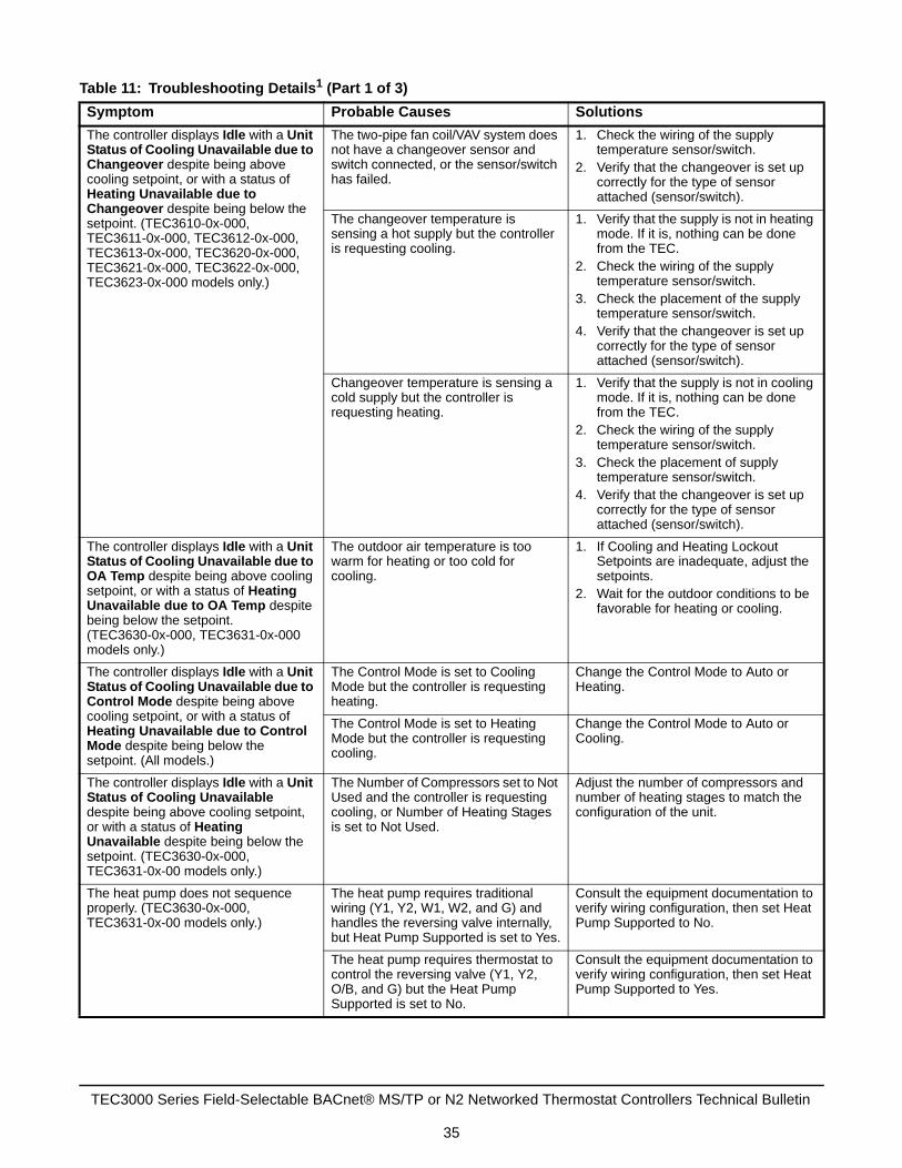
Table 11: Troubleshooting Details1 (Part 1 of 3)
Symptom Probable Causes Solutions
The controller displays Idle with a Unit Status of Cooling Unavailable due to Changeover despite being above cooling setpoint, or with a status of Heating Unavailable due to Changeover despite being below the setpoint. (TEC3610-0x-000, TEC3611-0x-000, TEC3612-0x-000, TEC3613-0x-000, TEC3620-0x-000, TEC3621-0x-000, TEC3622-0x-000, TEC3623-0x-000 models only.)
The two-pipe fan coil/VAV system does not have a changeover sensor and switch connected, or the sensor/switch has failed.
1. Check the wiring of the supply temperature sensor/switch.
2. Verify that the changeover is set up correctly for the type of sensor attached (sensor/switch).
The changeover temperature is sensing a hot supply but the controller is requesting cooling.
1. Verify that the supply is not in heating mode. If it is, nothing can be done from the TEC.
2. Check the wiring of the supply temperature sensor/switch.
3. Check the placement of the supply temperature sensor/switch.
4. Verify that the changeover is set up correctly for the type of sensor attached (sensor/switch).
Changeover temperature is sensing a cold supply but the controller is requesting heating.
1. Verify that the supply is not in cooling mode. If it is, nothing can be done from the TEC.
2. Check the wiring of the supply temperature sensor/switch.
3. Check the placement of supply temperature sensor/switch.
4. Verify that the changeover is set up correctly for the type of sensor attached (sensor/switch).
The controller displays Idle with a Unit Status of Cooling Unavailable due to OA Temp despite being above cooling setpoint, or with a status of Heating Unavailable due to OA Temp despite being below the setpoint. (TEC3630-0x-000, TEC3631-0x-000 models only.)
The outdoor air temperature is too warm for heating or too cold for cooling.
1. If Cooling and Heating Lockout Setpoints are inadequate, adjust the setpoints.
2. Wait for the outdoor conditions to be favorable for heating or cooling.
The controller displays Idle with a Unit Status of Cooling Unavailable due to Control Mode despite being above cooling setpoint, or with a status of Heating Unavailable due to Control Mode despite being below the setpoint. (All models.)
The Control Mode is set to Cooling Mode but the controller is requesting heating.
Change the Control Mode to Auto or Heating.
The Control Mode is set to Heating Mode but the controller is requesting cooling.
Change the Control Mode to Auto or Cooling.
The controller displays Idle with a Unit Status of Cooling Unavailable despite being above cooling setpoint, or with a status of Heating Unavailable despite being below the setpoint. (TEC3630-0x-000, TEC3631-0x-00 models only.)
The Number of Compressors set to Not Used and the controller is requesting cooling, or Number of Heating Stages is set to Not Used.
Adjust the number of compressors and number of heating stages to match the configuration of the unit.
The heat pump does not sequence properly. (TEC3630-0x-000, TEC3631-0x-00 models only.)
The heat pump requires traditional wiring (Y1, Y2, W1, W2, and G) and handles the reversing valve internally, but Heat Pump Supported is set to Yes.
Consult the equipment documentation to verify wiring configuration, then set Heat Pump Supported to No.
The heat pump requires thermostat to control the reversing valve (Y1, Y2, O/B, and G) but the Heat Pump Supported is set to No.
Consult the equipment documentation to verify wiring configuration, then set Heat Pump Supported to Yes.
TEC3000 Series Field-Selectable BACnet® MS/TP or N2 Networked Thermostat Controllers Technical Bulletin
35

The heat pump heats when it should be cooling, and cools when it should heat. (TEC3630-0x-000, TEC3631-0x-00 models only.)
Reversing Valve polarity is incorrectly set.
Consult the equipment documentation to verify reversing valve polarity, then adjust the Reversing Valve Polarity menu option accordingly.
The controller displays Cooling or Heating but the staged equipment shuts off. (TEC3610-0x-000, TEC3611-0x-000, TEC3612-0x-000, TEC3613-0x-000, TEC3630-0x-000, TEC3631-0x-00 models only.)
When in heating or cooling mode with staged equipment, the equipment cycles on and off during the cooling or heating operation in order to maintain setpoint.
Expected behavior.
The staged equipment shuts off above the cooling setpoint or below the heating setpoint. (TEC3610-0x-000, TEC3611-0x-000, TEC3612-0x-000, TEC3613-0x-000, TEC3630-0x-000, TEC3631-0x-00 models only.)
The PID control algorithm minimizes overshoot and energy usage for the particular equipment and zone, and may cycle the equipment prior to reaching setpoint.
Expected behavior.
The staged equipment cycles too rapidly or too slowly. (TEC3610-0x-000, TEC3611-0x-000, TEC3612-0x-000, TEC3613-0x-000, TEC3630-0x-000, TEC3631-0x-00 models only.)
The control band around the setpoint is determined by the minimum on/off times and is set incorrectly for the equipment, zone, or user preference. There is a tradeoff between reduced control band size and increased energy usage and equipment wear from increased cycling.
1. To tighten the control band, reduce the minimum on/off time settings. Minimal control band is achieved with a 60 second minimum on/off time.
2. To loosen the control band, increase the minimum on/off time settings.
The controller provides an error when trying to upgrade firmware. (All models.)
The USB drive is defective. Try a different USB drive.
The firmware package is corrupt. Try re-downloading the firmware image onto the USB drive and retry the upgrade.
The controller provides an error when trying to back up settings. (All models.)
The USB drive is defective. Try a different USB drive.
The controller provides an error when trying to restore settings from a backup. (All models.)
The USB drive is defective. Try a different USB drive.
The Restore file is corrupt. Try restoring a different backup file.
The Restore file is from an incompatible model TEC.
Ensure that the backup file being restored was from the same model TEC.
The controller is unable to access a USB drive. (All models.)
The drive is formatted as NTFS or another unsupported format. The TEC supports FAT and FAT32 formats only.
Reformat the USB drive, or try a different USB drive with a supported format.
The USB drive is defective. Try a different USB drive.
Table 11: Troubleshooting Details1 (Part 2 of 3)
Symptom Probable Causes Solutions
TEC3000 Series Field-Selectable BACnet® MS/TP or N2 Networked Thermostat Controllers Technical Bulletin
36
Related DocumentationSee Table 12 to locate information in related documentation.
The controller displays Board Mismatch. (All models.)
The I/O board that the display board is currently attached to does not match the one that initially shipped with the display board.
Attach the display board to the correct I/O board.
A hardware failure is causing the two boards to incorrectly identify themselves.
If problems persist, order replacement units and return the affected devices to Johnson Controls under the RMA program.
The controller displays Controller Fault. (All models.)
An internal fault was detected and the controller was unable to recover.
If problems persist, order replacement units and return the affected devices to Johnson Controls under the RMA program.
The Bell icon is displayed on the TEC home page. (All models.)
The fault has been detected on the TEC.
See Table 10 for TEC fault causes and resolution.
Partial Restore Complete is displayed when trying to restore settings from a backup file. (All models.)
Not all of the items in the backup file have been restored. This error can be caused by a value being out of the minimum or maximum range in the backup file. It may also occur if there are inconsistencies in the reliability of a setting in the backup file and on the TEC device.
1. Create a backup file on a USB drive for the TEC that is showing the issue.
2. Edit the backup file created in step 1 on a computer to reflect the desired settings.
3. Verify that the modified values are within minimum and maximum range in the backup file.
4. Restore the settings from the newly edited backup file on the TEC.
The NAE field point mapping process ends unexpectedly.
Selecting Map All to map the field points.
Select the displayed field points individually through the Point Mapping Utility. There are 60 field points available.
1. For common MS/TP troubleshooting information, refer to the MS/TP Communications Bus Technical Bulletin (LIT-12011034).
Table 12: TEC3000 Series Field-Selectable BACnet MS/TP or N2 Networked Thermostat Controllers Related DocumentationFor Information On See Document Document
Number
Applications, Features, and Benefits of the TEC3000 Series BACnet MS/TP or N2 Network Temperature and Humidity Thermostat Controllers
TEC3000 Series Field Selectable BACnet MS/TP or N2 Networked Thermostat Controllers Product Bulletin
LIT-12011954
TEC3000 Series Field Selectable BACnet MS/TP or N2 Networked Thermostat Controllers Catalog Page
LIT-1900896
Locating, Mounting, and Wiring a TEC3000 Series BACnet MS/TP or N2 Network Temperature and Humidity Thermostat Controller
TEC3000 Series On/Off or Floating Fan Coil and Zoning Thermostat Controllers with Dehumidification Capability Installation Instructions
Part No. 24-10787-6
TEC3000 Series Proportional Fan Coil and Zoning Thermostat Controllers with Dehumidification Capability Installation Instructions
Part No. 24-10788-0
TEC3000 Series Single- or Two-Stage Economizer Thermostat Controllers Installation Instructions
Part No.24-10789-5
Table 11: Troubleshooting Details1 (Part 3 of 3)
Symptom Probable Causes Solutions
TEC3000 Series Field-Selectable BACnet® MS/TP or N2 Networked Thermostat Controllers Technical Bulletin
37

European Single Point of Contact: NA/SA Single Point of Contact: APAC Single Point of Contact:
JOHNSON CONTROLSWESTENDHOF 345143 ESSENGERMANY
JOHNSON CONTROLS507 E MICHIGAN STMILWAUKEE WI 53202USA
JOHNSON CONTROLSC/O CONTROLS PRODUCT MANAGEMENTNO. 22 BLOCK D NEW DISTRICTWUXI JIANGSU PROVINCE 214142CHINA
Published in U.S.A. www.johnsoncontrols.com
TEC3000 Series Field-Selectable BACnet® MS/TP or N2 Networked Thermostat Controllers Technical Bulletin
38
Metasys® and Johnson Controls® are registered trademarks of Johnson Controls.All other marks herein are the marks of their respective owners. © 2017 Johnson Controls.
Building Technologies and Solutions507 E. Michigan Street, Milwaukee, WI 53202