Team Xtreme - cot-mect4276.tech.uh.educot-mect4276.tech.uh.edu/~mhodekar/Report6.pdf · Team Xtreme...
104
Team Xtreme 2017 Baja SAE Competition MECT 4276 – Spring 2017 Senior Design II– Report VI May 06, 2017 Keith Hernandez Team Lead Enrique DeLeon Mechanical Lead Manjula Hodekar Logistics Lead
Transcript of Team Xtreme - cot-mect4276.tech.uh.educot-mect4276.tech.uh.edu/~mhodekar/Report6.pdf · Team Xtreme...
Team Xtreme 2017 Baja SAE Competition
MECT 4276 – Spring 2017
Senior Design II– Report VI
May 06, 2017
Keith Hernandez
Team Lead
Enrique DeLeon
Mechanical Lead
Manjula Hodekar
Logistics Lead
Team Xtreme
2
Abstract
Team Xtreme will research, design, analyze and build a vehicle that meets the rules and
regulations of the 2017 Baja SAE competition and participate in the competition that will take
place in Pittsburg, Kansas on May 25-28, 2017. Using the existing frame from the Baja Brigade
build, Team Xtreme plans to have the vehicle in rolling chassis form by the end of December
2016. The team plans to achieve a top speed of 30 miles per hour on a flat surface and implement
instrumentation capable of real time data acquisition. Currently the team is working on the
braking fabrication and beginning the testing phase of the project. The suspension is complete
and consists of an unequal double A-arm set up in the front and trailing arms in the rear. The
steering assembly and the powertrain have all been fabricated. The project has an estimated cost
of $9,712 and fundraising is an ongoing process. The team has implemented several tools to help
stay on track and mitigate potential risks that may arise throughout the life of the project. A
Gantt chart has been developed to keep scheduling of tasks on track. The team’s progress is
monitored throughout the project via the timeline and work breakdown structure that has been
created. Weekly meetings and timesheets will also help the team schedule tasks and mitigate any
unforeseen risks.
Team Xtreme
3
Executive Summary
During the duration of the Senior Design I term, Team Xtreme could accomplish several tasks
and goals that will aid in completing the project and the challenges proposed by Professor
Pascali. The main challenge of the project consists of working with the frame that the Baja
Brigade senior design team fabricated. We will complete the vehicle with the parts that the Baja
Brigade team procured and raise funds throughout the senior design term for the remainder.
The team has agreed on deliverables for the duration of the project and conducted a significant
amount of research that will help in achieving the proposed deliverables. Team Xtreme also
agreed to split the process of designing and fabricating a vehicle in two stages. The first stage
was geared at meeting the deliverable of having a functioning suspension on the vehicle by the
end of December 2016. The team established communication and a working relationship with
Sean VanVactor, a key member of the Baja Brigade senior design team. With his help, the team
could get a better understanding of the vision they had for the design and fabrication of the
vehicle. Sean also agreed to be the team’s graduate advisor and continues to assist with
knowledge, resources, and support. In the second stage of the project the team will focus on
designing and fabricating the rest of the major components needed to complete the vehicle such
as: braking, steering, mounting of the engine, drivetrain and meeting all safety requirements.
The research phase was a key part of the project that helped familiarize the entire team with the
knowledge needed to design and fabricate a Baja SAE compliant vehicle. Due to the unique
nature of the challenge the team faced, it was agreed to leave the research phase for all major
components of the vehicle open for the duration of the project. The team has a project
management plan in place to ensure timely completion of the goals. With the incorporation of a
Gantt chart, project timeline, Work Breakdown Structure (WBS) and a Risk Matrix, the team
Team Xtreme
4
plans to ensure a timely completion of the project as well as the ability to mitigate any risks that
may arise throughout the duration of the project. These tools will continually evolve from the
projects conception all the way to the end and serve as critical tools for the team’s success.
The team finished fabrication on the frame by finishing the welding on all the members during
the first semester. A selected design analysis was also done on the frame to ensure the safety of
the driver. The team agreed to conduct a design analysis for two different crash scenarios. First, a
roll over crash at a free fall height of 7 feet considering one of the deliverables is to achieve a 7-
foot jump. The second crash analysis simulates a head-on collision at 30 mph considering one of
the deliverables is to achieve a top speed of 30 mph. Currently the team is working on the
braking fabrication and beginning the testing phase of the project. The suspension is complete
and consists of an unequal double A-arm set up in the front and trailing arms in the rear. The
steering assembly and the powertrain fabrication is complete.
Team Xtreme has also registered for the 2017 SAE Baja competition in Pittsburg Kansas. The
funds that will aid the team in the fabrication of the frame for the first semester goal have been
raised. A website has been created to represent the progress of the team and serves as a resource
to potential sponsors. Along the way the team has documented our trials and tribulations via
pictures and video to produce a short video summary of the incredible ride to this point.
Some lessons learned from Team Xtreme’s project are time management and forward planning.
These two aspects of the project go hand in hand; the lack of forward planning has had a
negative impact on the project. The team failed to plan the presentation dates accordingly and
therefore left very little time to prepare and produce material for the second and third
presentations. The first presentation was on 11/8/2016 which was very late into the first
semester. The second presentation was 11/29/2016 only three weeks after the first. Our final

Team Xtreme
5
presentation was on 12/10/2016 only 10 days after the second. We learned from this and made it
a point to be the first ones to schedule presentations at the beginning of the second semester. We
could have roughly four weeks between each presentation to give sufficient time to prepare for
each.
Team Xtreme
6
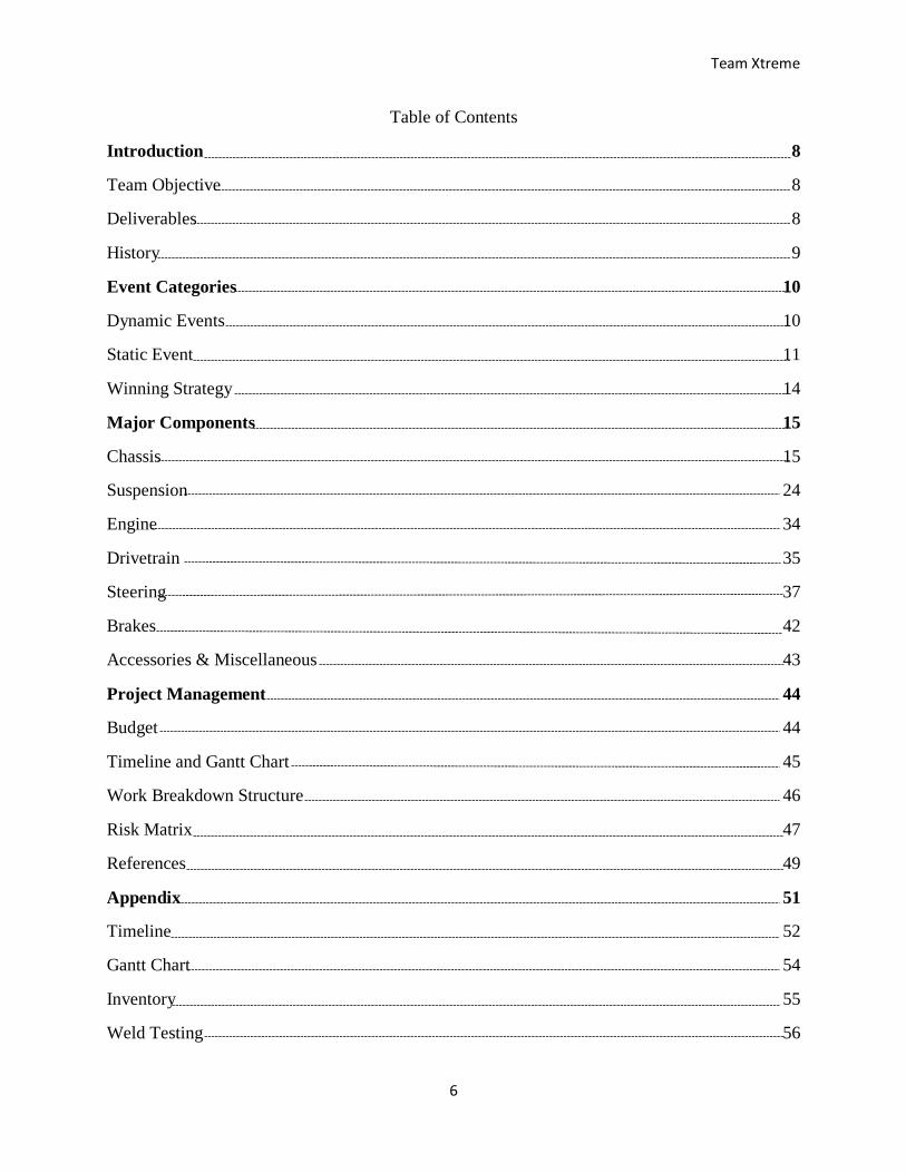
Table of Contents
Introduction 8
Team Objective 8
Deliverables 8
History 9
Event Categories 10
Dynamic Events 10
Static Event 11
Winning Strategy 14
Major Components 15
Chassis 15
Suspension 24
Engine 34
Drivetrain 35
Steering 37
Brakes 42
Accessories & Miscellaneous 43
Project Management 44
Budget 44
Timeline and Gantt Chart 45
Work Breakdown Structure 46
Risk Matrix 47
References 49
Appendix 51
Timeline 52
Gantt Chart 54
Inventory 55
Weld Testing 56
Team Xtreme
7
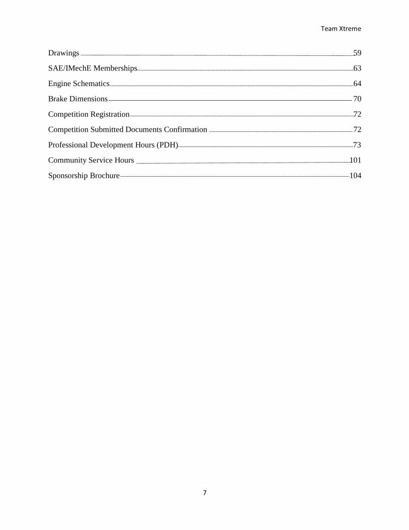
Drawings 59
SAE/IMechE Memberships 63
Engine Schematics 64
Brake Dimensions 70
Competition Registration 72
Competition Submitted Documents Confirmation 72
Professional Development Hours (PDH) 73
Community Service Hours 101
Sponsorship Brochure 104
Team Xtreme
8
Introduction
The Baja SAE Competition is one of the design series offered by the Society of Automotive
Engineers (SAE) that University students from around the world can compete in. University
students are required to design and fabricate a high performance off road vehicle. The
competition is a real-world scenario that lets students demonstrate their knowledge in the design
and fabrication of a dynamic mechanism. The Baja SAE Competition has a long list of rules and
regulations to ensure the safety of all participants however students can use creative and critical
thinking to design their vehicle in an innovative fashion. The focus of the Baja SAE challenge is
to promote teamwork and project management skills between team members. These qualities
become a key to producing a successful project.
Team Objective
The objective is to design and build a vehicle that meets the rules and regulations of the 2017
Baja SAE competition. Team Xtreme will represent the University of Houston and participate in
the competition that will take place in Pittsburg, Kansas on May 25-28, 2017.
Deliverables
Register for the 2017 Baja competition in Pittsburg, Kansas by the November 14, 2016
deadline
Have a Baja vehicle that is mechanically complete with a functioning suspension assembled
by December 2016
Manufacture carbon fiber uprights for the suspension
Achieve a vehicle weight under 400 lbs.
Pass the Baja SAE inspection for the competition
Team Xtreme
9
Achieve a top speed of 30 mph on a flat surface
Design a vehicle that can achieve a flat jump of 7 ft.
Implement instrumentation that is capable of data acquisition
The deliverables were approved by our instructor Raresh Pascali and are intended to be met by
May 2017. One important note is that to meet the second deliverable and have a vehicle that is
mechanically complete with a functioning suspension assembled by December 2016, Team
Xtreme will be using some of the components that were designed and fabricated by the Baja
Brigade senior design team.
History
The first Baja SAE Competition was held in 1976 at the University of South Carolina in Jackson,
SC. Ten teams registered for this event with ninety students participating. The competition was
eventually divided into 3 regions: East, Midwest, and West. In 1978, the first Midwest and West
regions competition was held in Milwaukee, WI, Arizona state university, and Phoenix, AZ
respectively. The number of teams that participated continued to grow every year after the first
event. By 2016, 100 teams registered with more than 1000 students participating in all three
regions. Over the years, the Baja SAE Competition has spread to other countries outside of
North America. Brazil’s first Baja SAE event was held in 1995 with 10 registered teams and 90
participating students. Korea’s first event was hosted by Yeungnam University in 1996 with 10
teams and 280 students. South Africa’s first event also started in 1996, hosted by the University
of Pretoria with 4 teams and 12 students.
Team Xtreme
10
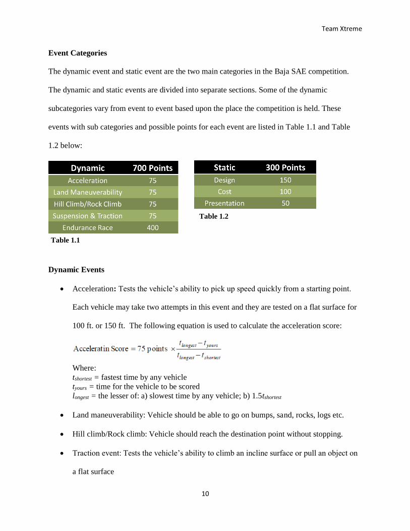
Event Categories
The dynamic event and static event are the two main categories in the Baja SAE competition.
The dynamic and static events are divided into separate sections. Some of the dynamic
subcategories vary from event to event based upon the place the competition is held. These
events with sub categories and possible points for each event are listed in Table 1.1 and Table
1.2 below:
Dynamic Events
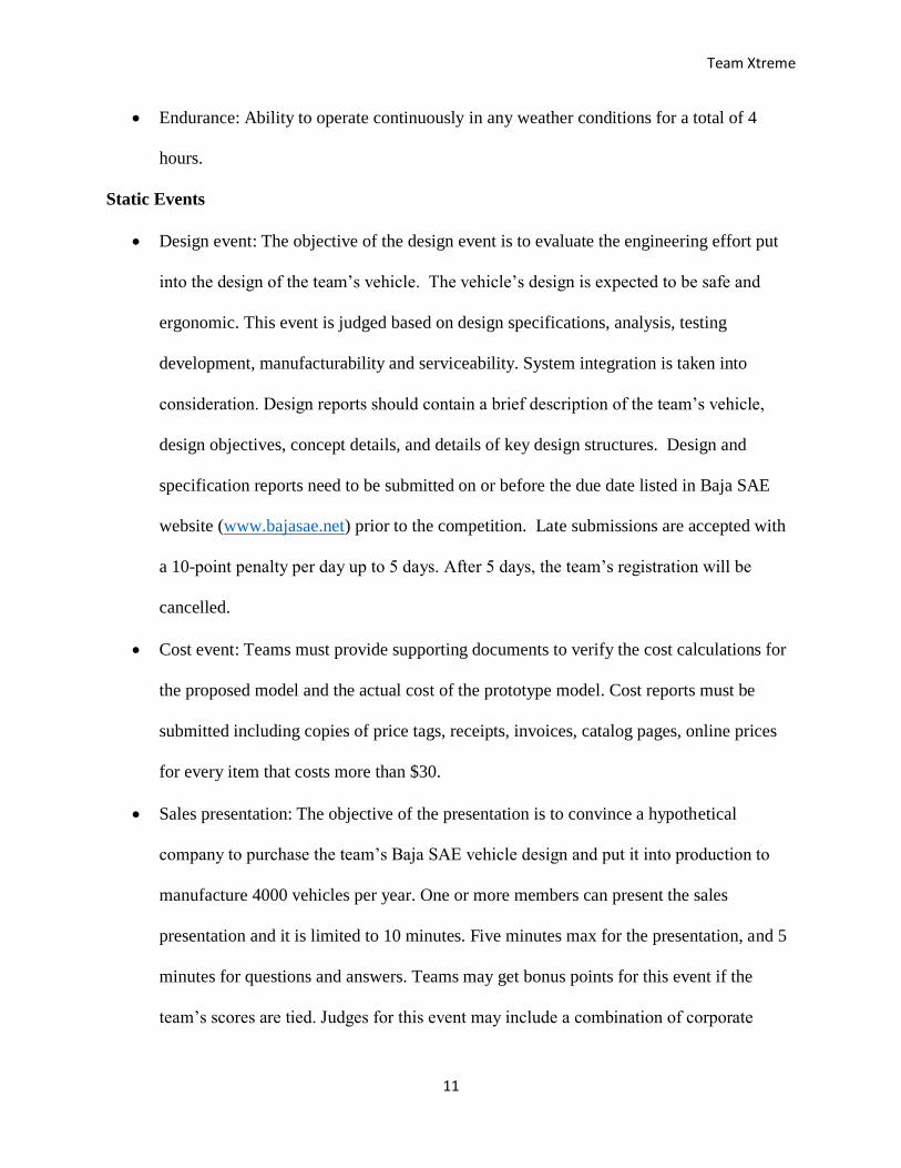
Acceleration: Tests the vehicle’s ability to pick up speed quickly from a starting point.
Each vehicle may take two attempts in this event and they are tested on a flat surface for
100 ft. or 150 ft. The following equation is used to calculate the acceleration score:
Where:
tshortest = fastest time by any vehicle
tyours = time for the vehicle to be scored
longest = the lesser of: a) slowest time by any vehicle; b) 1.5tshortest
Land maneuverability: Vehicle should be able to go on bumps, sand, rocks, logs etc.
Hill climb/Rock climb: Vehicle should reach the destination point without stopping.
Traction event: Tests the vehicle’s ability to climb an incline surface or pull an object on
a flat surface
Table 1.1
Table 1.2
Team Xtreme
11
Endurance: Ability to operate continuously in any weather conditions for a total of 4
hours.
Static Events
Design event: The objective of the design event is to evaluate the engineering effort put
into the design of the team’s vehicle. The vehicle’s design is expected to be safe and
ergonomic. This event is judged based on design specifications, analysis, testing
development, manufacturability and serviceability. System integration is taken into
consideration. Design reports should contain a brief description of the team’s vehicle,
design objectives, concept details, and details of key design structures. Design and
specification reports need to be submitted on or before the due date listed in Baja SAE
website (www.bajasae.net) prior to the competition. Late submissions are accepted with
a 10-point penalty per day up to 5 days. After 5 days, the team’s registration will be
cancelled.
Cost event: Teams must provide supporting documents to verify the cost calculations for
the proposed model and the actual cost of the prototype model. Cost reports must be
submitted including copies of price tags, receipts, invoices, catalog pages, online prices
for every item that costs more than $30.
Sales presentation: The objective of the presentation is to convince a hypothetical
company to purchase the team’s Baja SAE vehicle design and put it into production to
manufacture 4000 vehicles per year. One or more members can present the sales
presentation and it is limited to 10 minutes. Five minutes max for the presentation, and 5
minutes for questions and answers. Teams may get bonus points for this event if the
team’s scores are tied. Judges for this event may include a combination of corporate
Team Xtreme
12
executives who may have experience in marketing, production and finance as well as
engineering.
Design event:
The design event consists of two parts: Design evaluation and the design report. The
design report needs to be submitted before the competition. It includes a brief description of the
vehicle, vehicle concepts, the team’s design objectives, and the details about important features.
The team should be able to provide backup data, analysis, and testing techniques as well as
documents on request at the competition. A design specification sheet needs to be prepared using
the standard template that can be found at www.bajasae.net/go/downloads and submitted
electronically in .xlsx file format.
Design judges will review the report and inspect the vehicle on site for evaluation.
Design reports consist of eight (8) pages of A4 size paper with up to four pages of text and three
pages of vehicle drawings showing the vehicle’s front view, top view, and side view. Photos can
be included in the optional page. One optional page is allowed for photos, charts, graphs, etc.
Design reports must be submitted electronically in pdf format as a single file. Note: late
submissions will result in a ten-point penalty per day up to five days.
The design event is judged based on the design report, and the inspection of the vehicle
on site. Teams can bring supporting material such as photographs, drawings, plans, charts, and
sample components or materials. One or more team members can present the design
presentation. The design presentation is limited to a total of ten minutes, including one minute
for the clarification questions from the judges, and any team member can answer the questions.
Teams can bring a laptop, binders or posters to show documentation of the engineering work
they have completed.
Team Xtreme
13
Cost event:
The cost event consists of two related sections, 1. Cost report and 2. Prototype cost. The
cost report includes the background information and calculations to verify the vehicle’s actual
cost. The prototype cost consists of the actual cost of the prototype. The cost report must contain
a one-page summery sheet and cost documentation including copies of price tags, receipts,
invoices, catalog pages, and online prices for every item that costs more than $30. Teams also
need to bring a hard copy of the cost report to the competition site. The prototype cost score will
be calculated using the following formula:
𝑃𝑟𝑜𝑡𝑜𝑡𝑦𝑝𝑒 𝐶𝑜𝑠𝑡 = 85 𝑝𝑜𝑖𝑛𝑡𝑠 x C max −Cyours
C max −𝐶𝑙𝑜𝑤
Where:
Cyours =Vehicle cost, as corrected
Clow = Lowest vehicle cost, corrected
Cmax = Highest Vehicle cost, as corrected
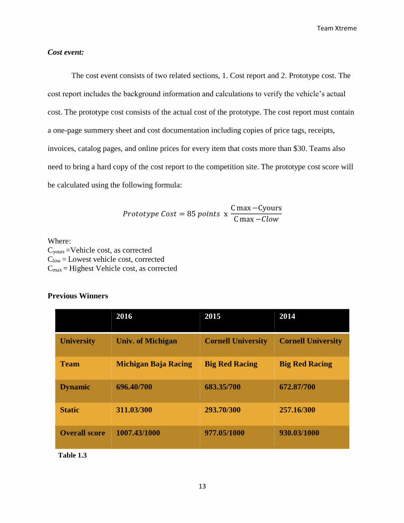
Previous Winners
2016 2015 2014
University Univ. of Michigan Cornell University Cornell University
Team Michigan Baja Racing Big Red Racing Big Red Racing
Dynamic 696.40/700 683.35/700 672.87/700
Static 311.03/300 293.70/300 257.16/300
Overall score 1007.43/1000 977.05/1000 930.03/1000
Table 1.3
Team Xtreme
14
Winning strategy
Improvement: Most of the top ten teams are using the same vehicles for many
competitions. These teams are making continuous improvements on the vehicle from the
previous competition. They are focusing on the events that they scored low points in the
previous competition.
Funding: Many of the top 10 teams received most the funds from their respective
university.
Vehicle Weight: Winning teams achieved a vehicle weight of less than 400 lbs. Some of
the top ten teams used ultra-high molecular weight polyethylene materials for the body,
light weight hammock materials for the seats, and light weight composite materials for
the floor. By using these materials, they could keep their vehicle weight under 400lbs.
Achieving maximum points in static event: They also used some electronic devices such
as LCD monitors, driver communication system, and speed sensors. Using these devises
effectively they could score bonus points in the static events.
SAE Competition Submitted Documents (See Appendix)
Frame documents: Frame check documentation including material test reports and weld
specs.
Cost Report: Cost calculations and supporting documents.
Design Documents: Design drawings and design specifications.
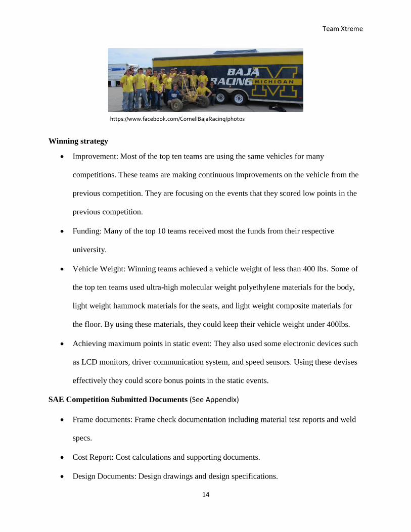
https://www.facebook.com/CornellBajaRacing/photos
Team Xtreme
15
Major Design Components
The major components of the Baja SAE vehicle are the chassis, suspension, engine,
transmission, brakes, and steering. Each component was researched individually to calculate
costs, availability and standards used throughout other vehicles participating in the Baja SAE
competition.
Chassis
The chassis is a series of tubes connected to form a coherent structure. The chassis provides a
rigid connection between the rear and front suspension and creates and overall structural support
for other necessary systems of the vehicle. The design of the chassis is important to support the
other components in their respective positions. It also serves as the base of the entire vehicle. It is
extremely important because it provides the necessary protection for the driver if the vehicle is to
receive a substantial amount off impact due to a crash or roll over.
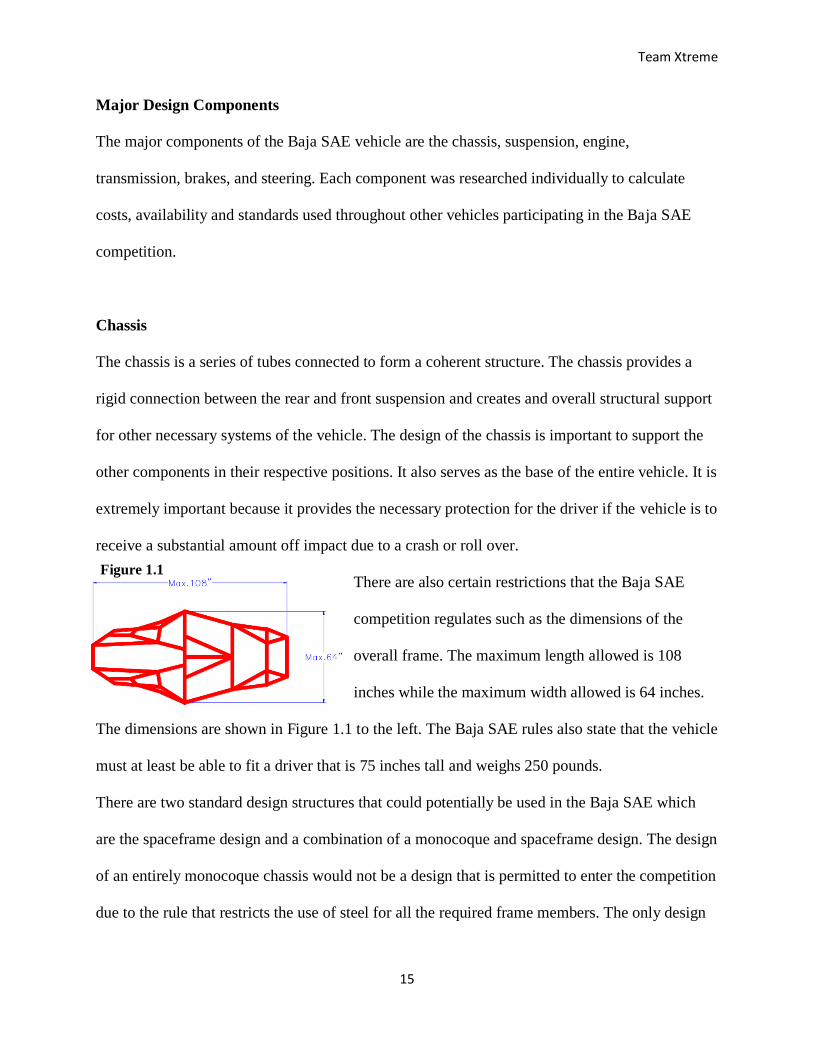
There are also certain restrictions that the Baja SAE
competition regulates such as the dimensions of the
overall frame. The maximum length allowed is 108
inches while the maximum width allowed is 64 inches.
The dimensions are shown in Figure 1.1 to the left. The Baja SAE rules also state that the vehicle
must at least be able to fit a driver that is 75 inches tall and weighs 250 pounds.
There are two standard design structures that could potentially be used in the Baja SAE which
are the spaceframe design and a combination of a monocoque and spaceframe design. The design
of an entirely monocoque chassis would not be a design that is permitted to enter the competition
due to the rule that restricts the use of steel for all the required frame members. The only design
Figure 1.1
Team Xtreme
16
that would be allowed would be a hybrid version of the spaceframe design in combination with a
monocoque design that would have the body panels double as stress members. Although a hybrid
version of that design would be innovative and advantageous, the spaceframe design is widely
used for the vehicles that participate in the Baja SAE competition because of the ease of
fabrication of the structure and the ability to easily make modifications if needed.
To meet the deliverable of having a complete rolling chassis by the end of December 2016,
under the approval of the instructor, the frame that was designed and fabricated by the Baja
Brigade senior design team will be completed by Team Xtreme. The team will complete the
welding on the frame and build on the design that was originally considered by the Baja Brigade
team. The team will reconsider the material and design in the second semester and make
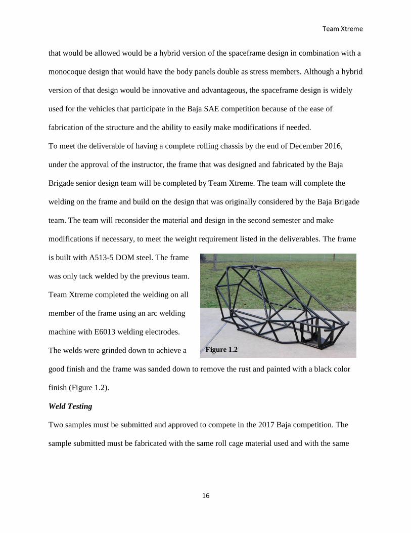
modifications if necessary, to meet the weight requirement listed in the deliverables. The frame
is built with A513-5 DOM steel. The frame
was only tack welded by the previous team.
Team Xtreme completed the welding on all
member of the frame using an arc welding
machine with E6013 welding electrodes.
The welds were grinded down to achieve a
good finish and the frame was sanded down to remove the rust and painted with a black color
finish (Figure 1.2).
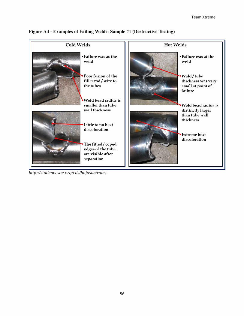
Weld Testing
Two samples must be submitted and approved to compete in the 2017 Baja competition. The
sample submitted must be fabricated with the same roll cage material used and with the same
Figure 1.2
Team Xtreme
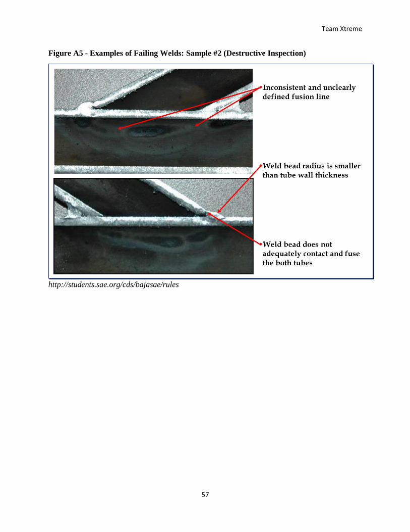
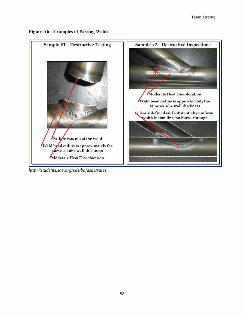
17
welding process and tools. The inspection requirements and the images of the passing welding
and failing welds are listed in the Appendix, Figures A4-A6.
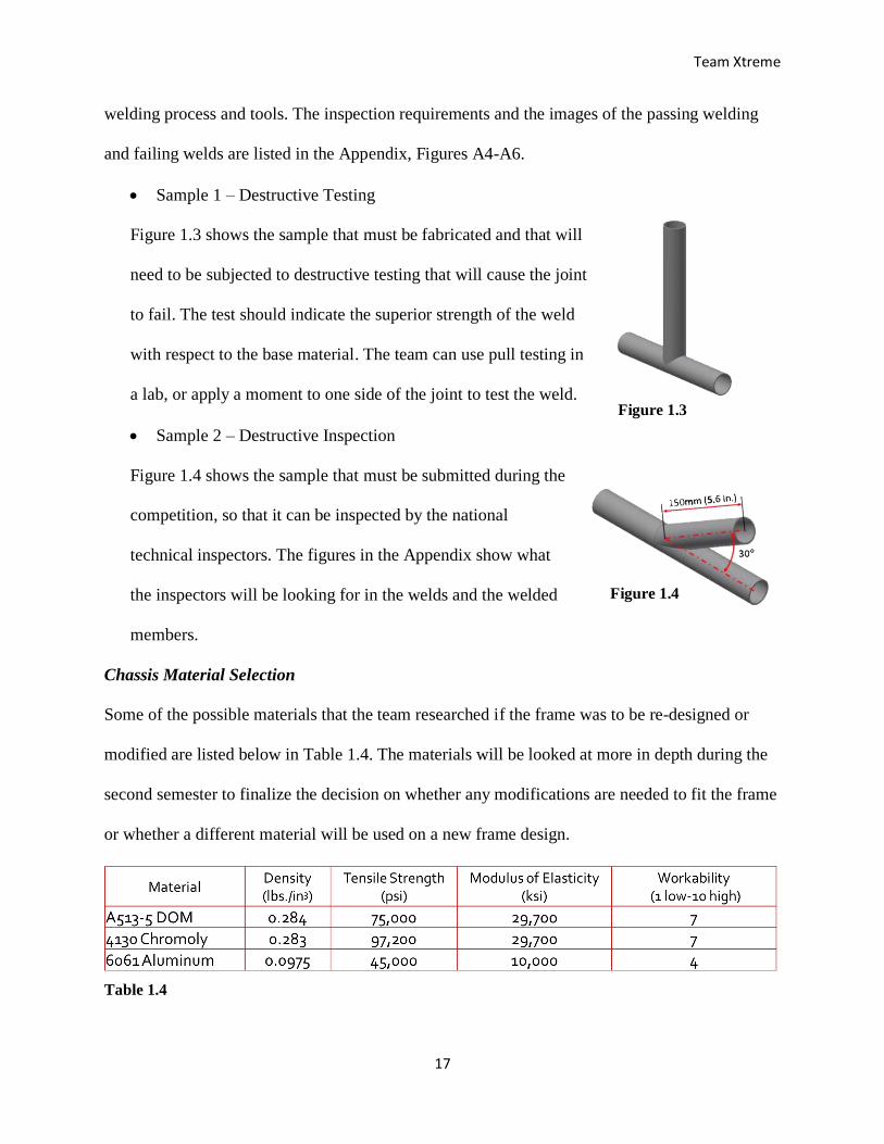
Sample 1 – Destructive Testing
Figure 1.3 shows the sample that must be fabricated and that will
need to be subjected to destructive testing that will cause the joint
to fail. The test should indicate the superior strength of the weld
with respect to the base material. The team can use pull testing in
a lab, or apply a moment to one side of the joint to test the weld.
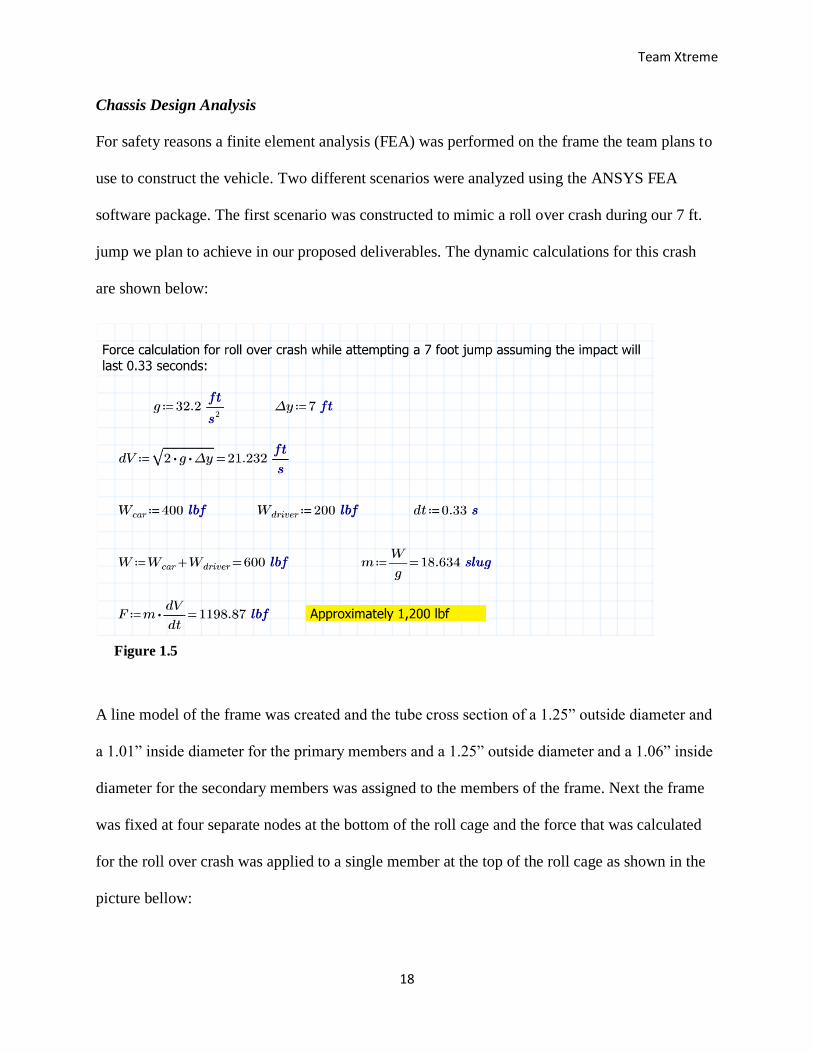
Sample 2 – Destructive Inspection
Figure 1.4 shows the sample that must be submitted during the
competition, so that it can be inspected by the national
technical inspectors. The figures in the Appendix show what
the inspectors will be looking for in the welds and the welded
members.
Chassis Material Selection
Some of the possible materials that the team researched if the frame was to be re-designed or
modified are listed below in Table 1.4. The materials will be looked at more in depth during the
second semester to finalize the decision on whether any modifications are needed to fit the frame
or whether a different material will be used on a new frame design.
Table 1.4
Figure 1.3
Figure 1.4
Team Xtreme
18
Chassis Design Analysis
For safety reasons a finite element analysis (FEA) was performed on the frame the team plans to
use to construct the vehicle. Two different scenarios were analyzed using the ANSYS FEA
software package. The first scenario was constructed to mimic a roll over crash during our 7 ft.
jump we plan to achieve in our proposed deliverables. The dynamic calculations for this crash
are shown below:
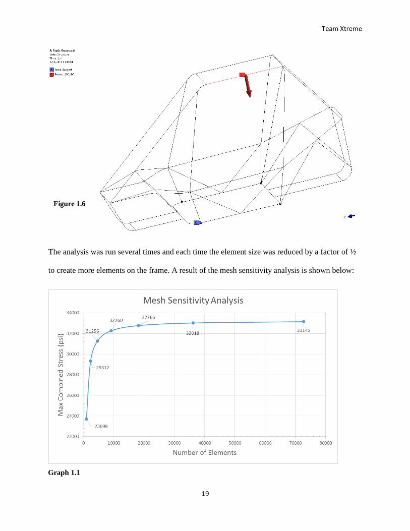
A line model of the frame was created and the tube cross section of a 1.25” outside diameter and
a 1.01” inside diameter for the primary members and a 1.25” outside diameter and a 1.06” inside
diameter for the secondary members was assigned to the members of the frame. Next the frame
was fixed at four separate nodes at the bottom of the roll cage and the force that was calculated
for the roll over crash was applied to a single member at the top of the roll cage as shown in the
picture bellow:
Figure 1.5
Team Xtreme
19
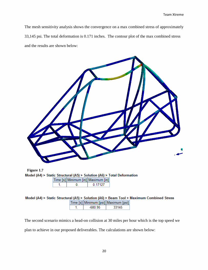
The analysis was run several times and each time the element size was reduced by a factor of ½
to create more elements on the frame. A result of the mesh sensitivity analysis is shown below:
Graph 1.1
Figure 1.6
Team Xtreme
20
The mesh sensitivity analysis shows the convergence on a max combined stress of approximately
33,145 psi. The total deformation is 0.171 inches. The contour plot of the max combined stress
and the results are shown below:
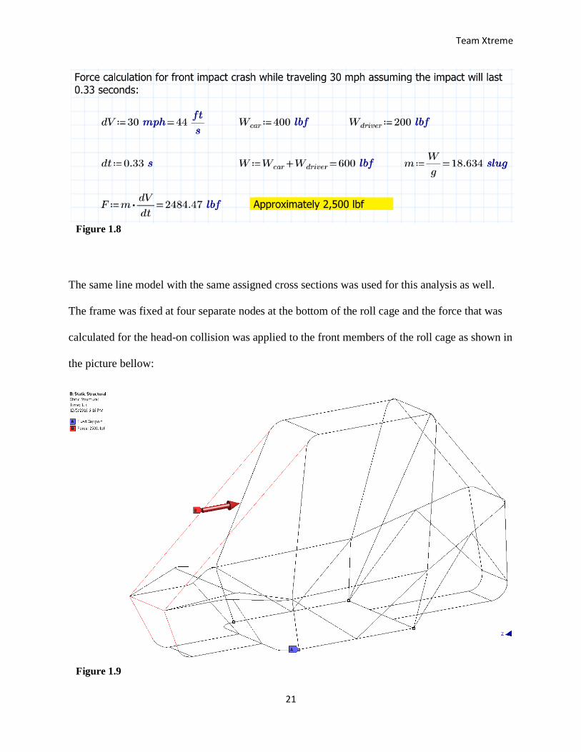
The second scenario mimics a head-on collision at 30 miles per hour which is the top speed we
plan to achieve in our proposed deliverables. The calculations are shown below:
Figure 1.7
Team Xtreme
21
The same line model with the same assigned cross sections was used for this analysis as well.
The frame was fixed at four separate nodes at the bottom of the roll cage and the force that was
calculated for the head-on collision was applied to the front members of the roll cage as shown in
the picture bellow:
Figure 1.8
Figure 1.9
Team Xtreme
22
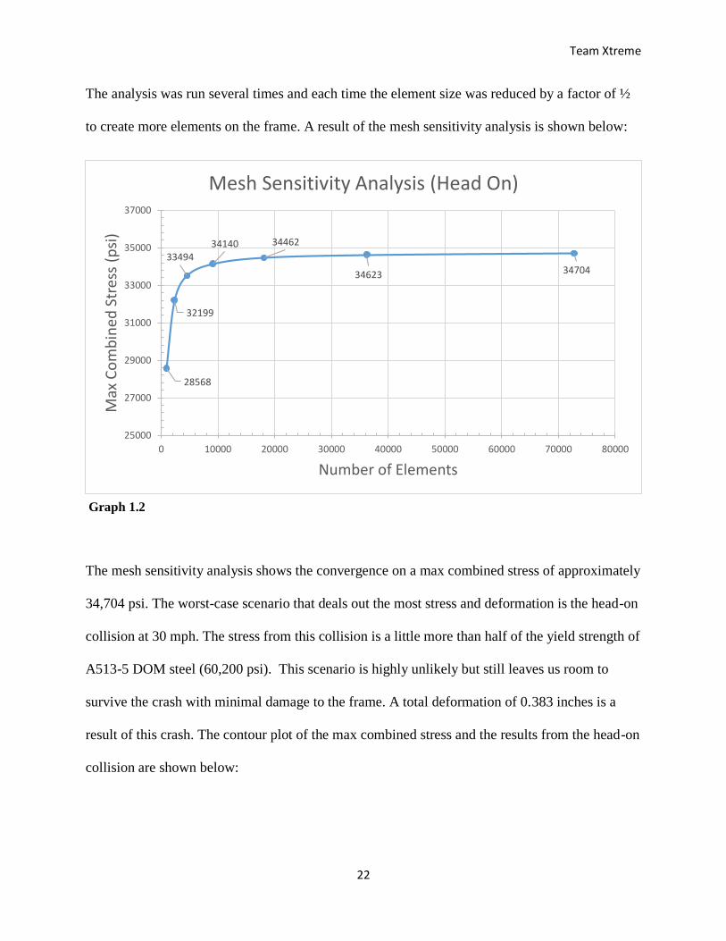
The analysis was run several times and each time the element size was reduced by a factor of ½
to create more elements on the frame. A result of the mesh sensitivity analysis is shown below:
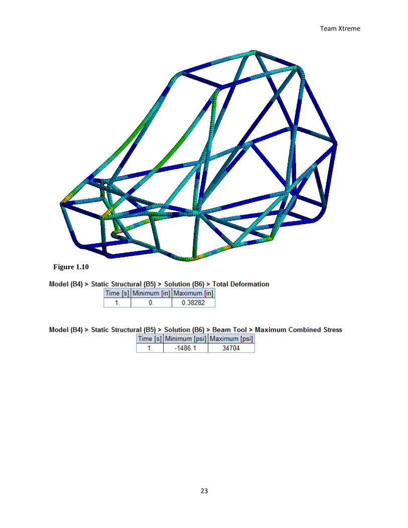
The mesh sensitivity analysis shows the convergence on a max combined stress of approximately
34,704 psi. The worst-case scenario that deals out the most stress and deformation is the head-on
collision at 30 mph. The stress from this collision is a little more than half of the yield strength of
A513-5 DOM steel (60,200 psi). This scenario is highly unlikely but still leaves us room to
survive the crash with minimal damage to the frame. A total deformation of 0.383 inches is a
result of this crash. The contour plot of the max combined stress and the results from the head-on
collision are shown below:
28568
32199
3349434140 34462
34623 34704
25000
27000
29000
31000
33000
35000
37000
0 10000 20000 30000 40000 50000 60000 70000 80000
Max
Co
mb
ine
d S
tres
s (p
si)
Number of Elements
Mesh Sensitivity Analysis (Head On)
Graph 1.2
Team Xtreme
23
Figure 1.10
Team Xtreme
24
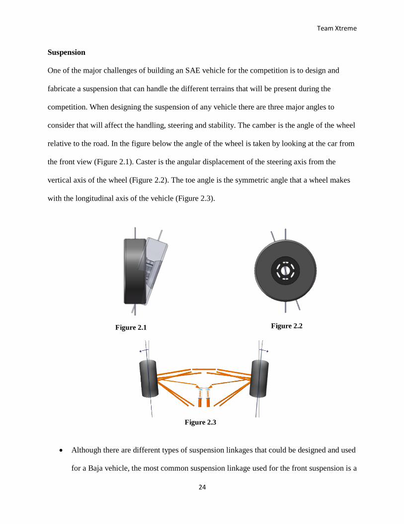
Suspension
One of the major challenges of building an SAE vehicle for the competition is to design and
fabricate a suspension that can handle the different terrains that will be present during the
competition. When designing the suspension of any vehicle there are three major angles to
consider that will affect the handling, steering and stability. The camber is the angle of the wheel
relative to the road. In the figure below the angle of the wheel is taken by looking at the car from
the front view (Figure 2.1). Caster is the angular displacement of the steering axis from the
vertical axis of the wheel (Figure 2.2). The toe angle is the symmetric angle that a wheel makes
with the longitudinal axis of the vehicle (Figure 2.3).
Although there are different types of suspension linkages that could be designed and used
for a Baja vehicle, the most common suspension linkage used for the front suspension is a
Figure 2.1 Figure 2.2
Figure 2.3
Team Xtreme
25
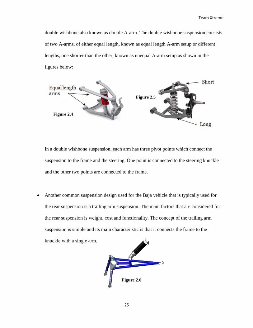
double wishbone also known as double A-arm. The double wishbone suspension consists
of two A-arms, of either equal length, known as equal length A-arm setup or different
lengths, one shorter than the other, known as unequal A-arm setup as shown in the
figures below:
In a double wishbone suspension, each arm has three pivot points which connect the
suspension to the frame and the steering. One point is connected to the steering knuckle
and the other two points are connected to the frame.
Another common suspension design used for the Baja vehicle that is typically used for
the rear suspension is a trailing arm suspension. The main factors that are considered for
the rear suspension is weight, cost and functionality. The concept of the trailing arm
suspension is simple and its main characteristic is that it connects the frame to the
knuckle with a single arm.
Figure 2.6
Figure 2.4
Figure 2.5
Team Xtreme
26
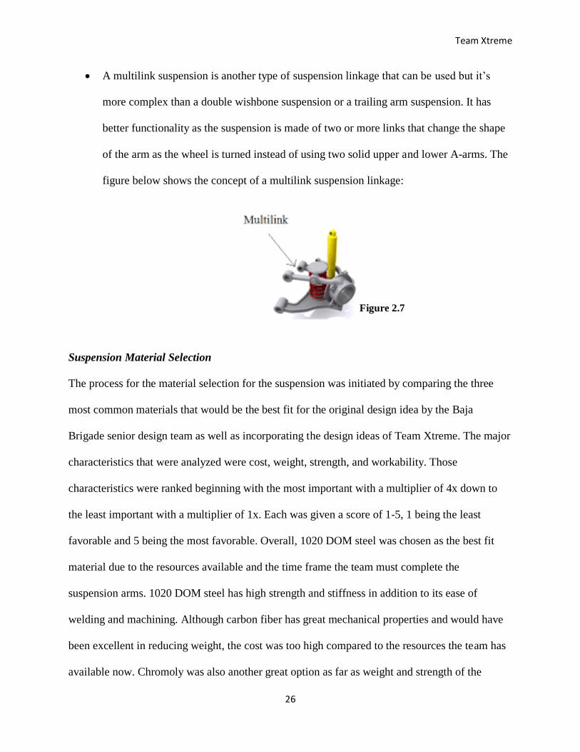
A multilink suspension is another type of suspension linkage that can be used but it’s
more complex than a double wishbone suspension or a trailing arm suspension. It has
better functionality as the suspension is made of two or more links that change the shape
of the arm as the wheel is turned instead of using two solid upper and lower A-arms. The
figure below shows the concept of a multilink suspension linkage:
Suspension Material Selection
The process for the material selection for the suspension was initiated by comparing the three
most common materials that would be the best fit for the original design idea by the Baja
Brigade senior design team as well as incorporating the design ideas of Team Xtreme. The major
characteristics that were analyzed were cost, weight, strength, and workability. Those
characteristics were ranked beginning with the most important with a multiplier of 4x down to
the least important with a multiplier of 1x. Each was given a score of 1-5, 1 being the least
favorable and 5 being the most favorable. Overall, 1020 DOM steel was chosen as the best fit
material due to the resources available and the time frame the team must complete the
suspension arms. 1020 DOM steel has high strength and stiffness in addition to its ease of
welding and machining. Although carbon fiber has great mechanical properties and would have
been excellent in reducing weight, the cost was too high compared to the resources the team has
available now. Chromoly was also another great option as far as weight and strength of the
Figure 2.7
Team Xtreme
27
material, but it also fell behind in cost. Table 2.1 below shows the selection material matrix for
the suspension’s upper and lower arms.
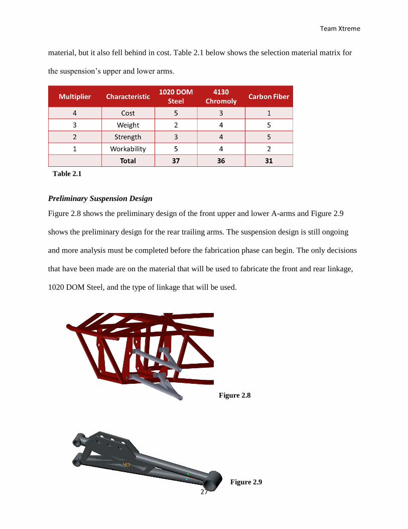
Preliminary Suspension Design
Figure 2.8 shows the preliminary design of the front upper and lower A-arms and Figure 2.9
shows the preliminary design for the rear trailing arms. The suspension design is still ongoing
and more analysis must be completed before the fabrication phase can begin. The only decisions
that have been made are on the material that will be used to fabricate the front and rear linkage,
1020 DOM Steel, and the type of linkage that will be used.
Table 2.1
Figure 2.8
Figure 2.9
Team Xtreme
28
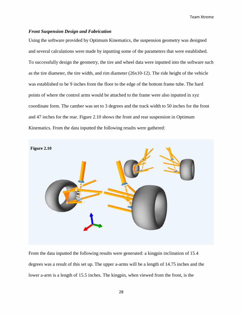
Front Suspension Design and Fabrication
Using the software provided by Optimum Kinematics, the suspension geometry was designed
and several calculations were made by inputting some of the parameters that were established.
To successfully design the geometry, the tire and wheel data were inputted into the software such
as the tire diameter, the tire width, and rim diameter (26x10-12). The ride height of the vehicle
was established to be 9 inches from the floor to the edge of the bottom frame tube. The hard
points of where the control arms would be attached to the frame were also inputted in xyz
coordinate form. The camber was set to 3 degrees and the track width to 50 inches for the front
and 47 inches for the rear. Figure 2.10 shows the front and rear suspension in Optimum
Kinematics. From the data inputted the following results were gathered:
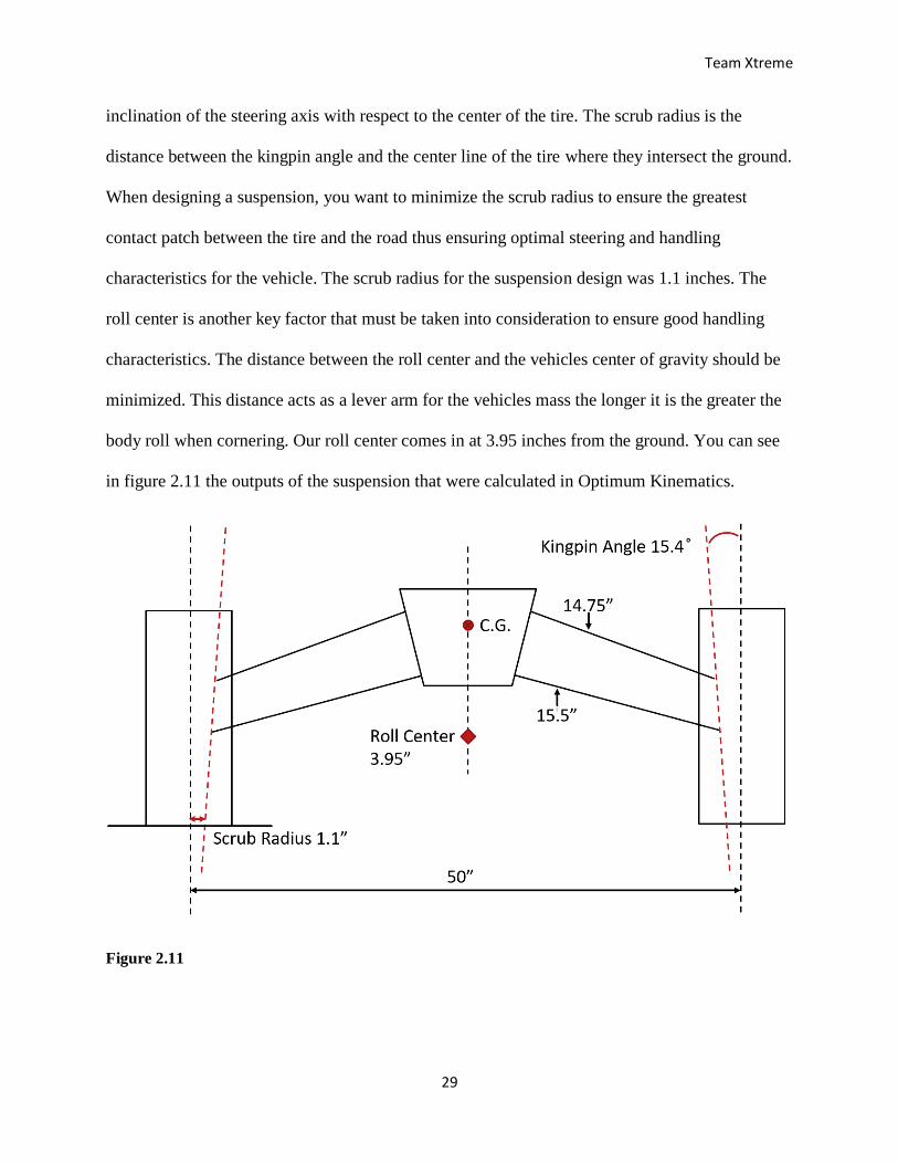
From the data inputted the following results were generated: a kingpin inclination of 15.4
degrees was a result of this set up. The upper a-arms will be a length of 14.75 inches and the
lower a-arm is a length of 15.5 inches. The kingpin, when viewed from the front, is the
Figure 2.10
Team Xtreme
29
inclination of the steering axis with respect to the center of the tire. The scrub radius is the
distance between the kingpin angle and the center line of the tire where they intersect the ground.
When designing a suspension, you want to minimize the scrub radius to ensure the greatest
contact patch between the tire and the road thus ensuring optimal steering and handling
characteristics for the vehicle. The scrub radius for the suspension design was 1.1 inches. The
roll center is another key factor that must be taken into consideration to ensure good handling
characteristics. The distance between the roll center and the vehicles center of gravity should be
minimized. This distance acts as a lever arm for the vehicles mass the longer it is the greater the
body roll when cornering. Our roll center comes in at 3.95 inches from the ground. You can see
in figure 2.11 the outputs of the suspension that were calculated in Optimum Kinematics.
Figure 2.11
Team Xtreme
30
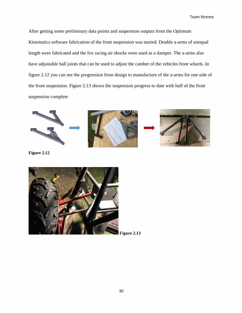
After getting some preliminary data points and suspension outputs from the Optimum
Kinematics software fabrication of the front suspension was started. Double a-arms of unequal
length were fabricated and the fox racing air shocks were used as a damper. The a-arms also
have adjustable ball joints that can be used to adjust the camber of the vehicles front wheels. In
figure 2.12 you can see the progression from design to manufacture of the a-arms for one side of
the front suspension. Figure 2.13 shows the suspension progress to date with half of the front
suspension complete
Figure 2.12
Figure 2.13
Team Xtreme
31
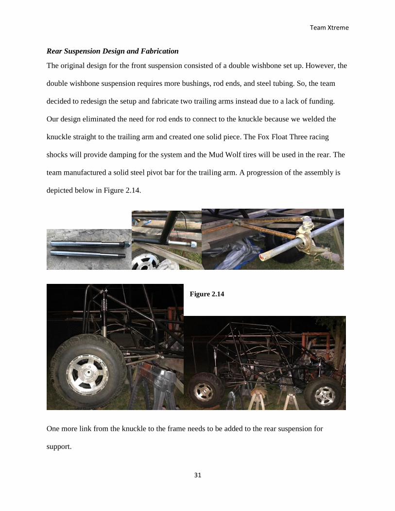
Rear Suspension Design and Fabrication
The original design for the front suspension consisted of a double wishbone set up. However, the
double wishbone suspension requires more bushings, rod ends, and steel tubing. So, the team
decided to redesign the setup and fabricate two trailing arms instead due to a lack of funding.
Our design eliminated the need for rod ends to connect to the knuckle because we welded the
knuckle straight to the trailing arm and created one solid piece. The Fox Float Three racing
shocks will provide damping for the system and the Mud Wolf tires will be used in the rear. The
team manufactured a solid steel pivot bar for the trailing arm. A progression of the assembly is
depicted below in Figure 2.14.
One more link from the knuckle to the frame needs to be added to the rear suspension for
support.
Figure 2.14
Team Xtreme
32
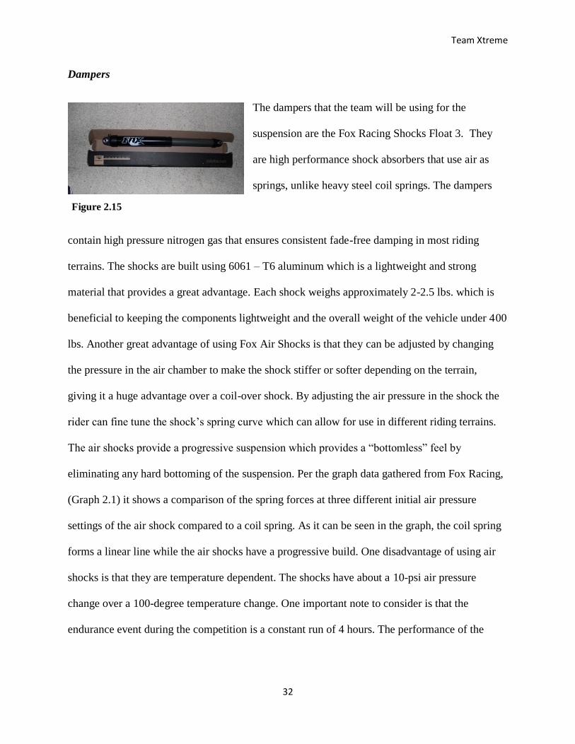
Dampers
The dampers that the team will be using for the
suspension are the Fox Racing Shocks Float 3. They
are high performance shock absorbers that use air as
springs, unlike heavy steel coil springs. The dampers
contain high pressure nitrogen gas that ensures consistent fade-free damping in most riding
terrains. The shocks are built using 6061 – T6 aluminum which is a lightweight and strong
material that provides a great advantage. Each shock weighs approximately 2-2.5 lbs. which is
beneficial to keeping the components lightweight and the overall weight of the vehicle under 400
lbs. Another great advantage of using Fox Air Shocks is that they can be adjusted by changing
the pressure in the air chamber to make the shock stiffer or softer depending on the terrain,
giving it a huge advantage over a coil-over shock. By adjusting the air pressure in the shock the
rider can fine tune the shock’s spring curve which can allow for use in different riding terrains.
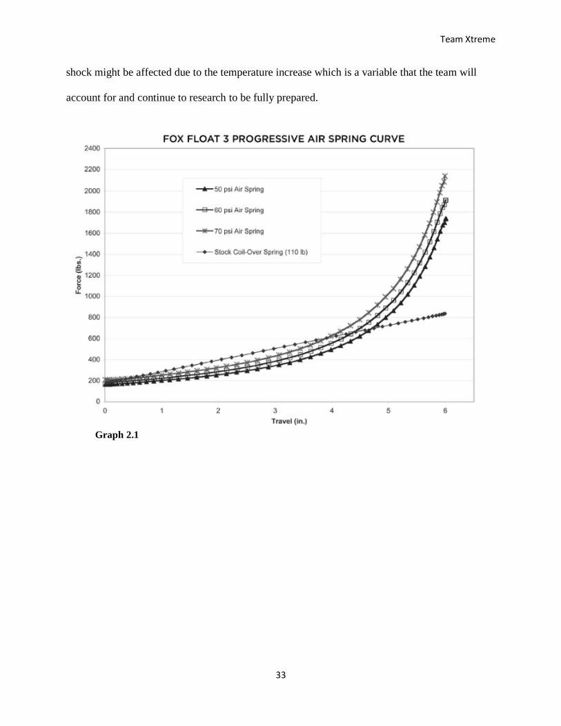
The air shocks provide a progressive suspension which provides a “bottomless” feel by
eliminating any hard bottoming of the suspension. Per the graph data gathered from Fox Racing,
(Graph 2.1) it shows a comparison of the spring forces at three different initial air pressure
settings of the air shock compared to a coil spring. As it can be seen in the graph, the coil spring
forms a linear line while the air shocks have a progressive build. One disadvantage of using air
shocks is that they are temperature dependent. The shocks have about a 10-psi air pressure
change over a 100-degree temperature change. One important note to consider is that the
endurance event during the competition is a constant run of 4 hours. The performance of the
Figure 2.15
Team Xtreme
33
shock might be affected due to the temperature increase which is a variable that the team will
account for and continue to research to be fully prepared.
Graph 2.1
Team Xtreme
34
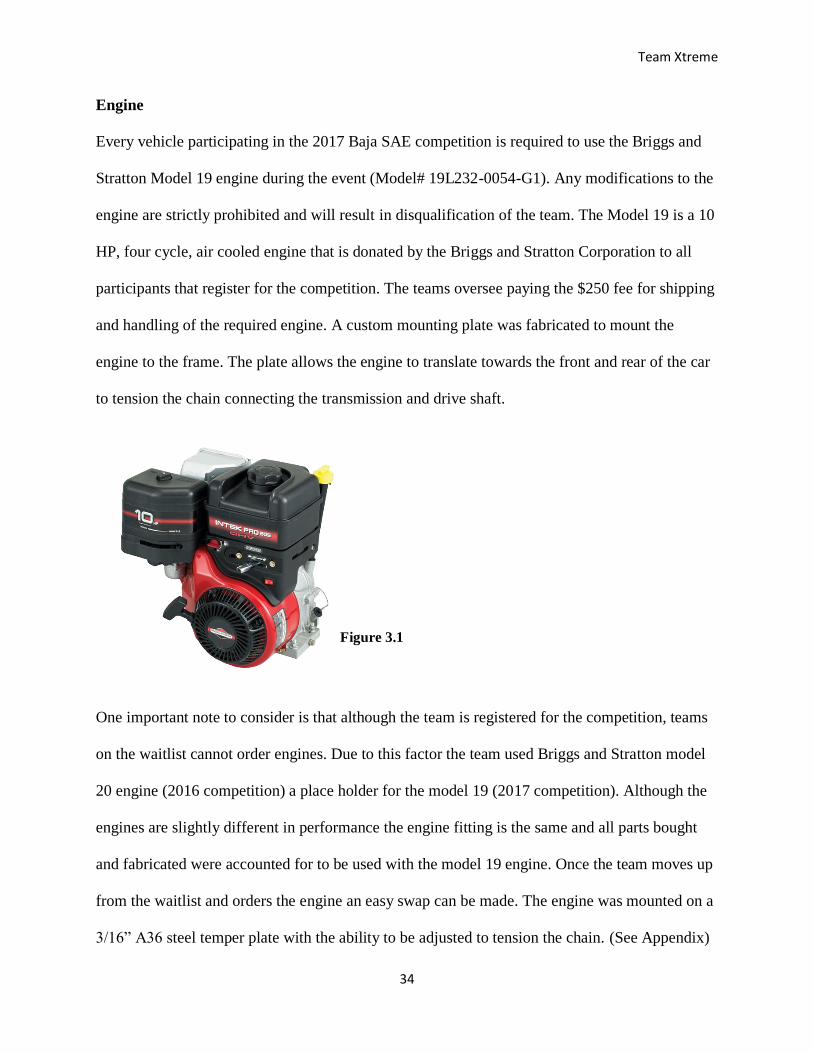
Engine
Every vehicle participating in the 2017 Baja SAE competition is required to use the Briggs and
Stratton Model 19 engine during the event (Model# 19L232-0054-G1). Any modifications to the
engine are strictly prohibited and will result in disqualification of the team. The Model 19 is a 10
HP, four cycle, air cooled engine that is donated by the Briggs and Stratton Corporation to all
participants that register for the competition. The teams oversee paying the $250 fee for shipping
and handling of the required engine. A custom mounting plate was fabricated to mount the
engine to the frame. The plate allows the engine to translate towards the front and rear of the car
to tension the chain connecting the transmission and drive shaft.
One important note to consider is that although the team is registered for the competition, teams
on the waitlist cannot order engines. Due to this factor the team used Briggs and Stratton model
20 engine (2016 competition) a place holder for the model 19 (2017 competition). Although the
engines are slightly different in performance the engine fitting is the same and all parts bought
and fabricated were accounted for to be used with the model 19 engine. Once the team moves up
from the waitlist and orders the engine an easy swap can be made. The engine was mounted on a
3/16” A36 steel temper plate with the ability to be adjusted to tension the chain. (See Appendix)
Figure 3.1
Team Xtreme
35
Drivetrain
The drivetrain is a very crucial component of the vehicle. It is the component that delivers the
power from the engine to the wheels. One major factor to consider is that every team in the
competition will be using the same engine without any modifications, so to achieve more
efficiency in the power that is delivered to the wheels; the team must closely look at the design
of the drivetrain. Another aspect that is important to the team is meeting the deliverable which
states that the Baja vehicle will be able to achieve a top speed of at least 30 mph on a flat surface.
To successfully design a vehicle that not only meets that deliverable but can also deliver enough
power to handle the rough terrains of the competition certain design constraints must be
considered such as the engine limitations that have been specified. The need for a lightweight
and compact transmission that is susceptible to the space allotted in the frame and that can adjust
from high to low gears depending on the terrain encountered during the competition. The two
possible options for the drivetrain that the team is currently considering are either a manual
transmission or an automatic transmission and the advantages and disadvantages that each one
has. Automatic transmissions such as a Continuously Variable Transmission (CVT) are the most
commonly used in the vehicles that participate in the competition. CVT’s are very effective in
the competition due to their ability to automatically adjust to the traction requirements. A CVT
has a greater shifting range than manual transmissions and it is best suited for acceleration. The
challenge with CVT transmissions is that tuning is a very crucial aspect and to tune it expertise
and knowledge are required. In manual transmissions, torque and speed are restricted on gear
shifting but they are less complex than CVT’s and tend to be less costly as well. Manual
transmissions also require less maintenance and give the driver more control on the performance
Team Xtreme
36
of the vehicle. Another benefit is that manual transmissions tend to also weigh less than their
counterpart automatic transmissions.
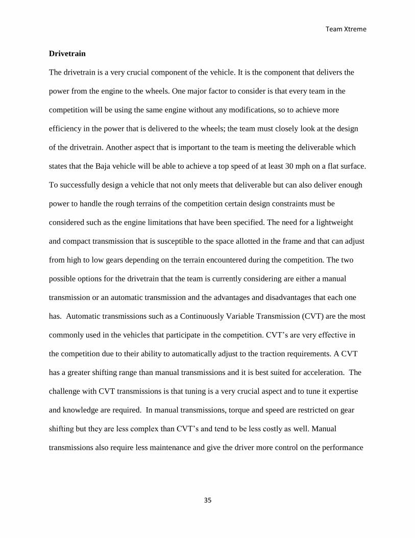
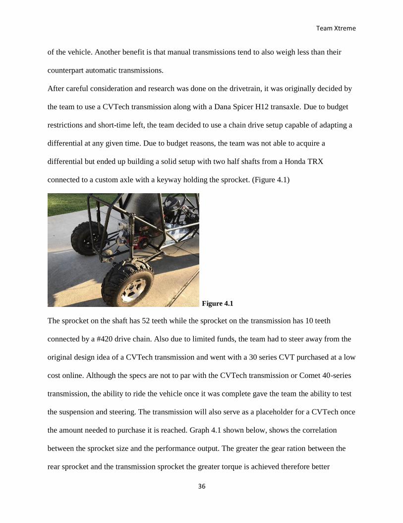
After careful consideration and research was done on the drivetrain, it was originally decided by
the team to use a CVTech transmission along with a Dana Spicer H12 transaxle. Due to budget
restrictions and short-time left, the team decided to use a chain drive setup capable of adapting a
differential at any given time. Due to budget reasons, the team was not able to acquire a
differential but ended up building a solid setup with two half shafts from a Honda TRX
connected to a custom axle with a keyway holding the sprocket. (Figure 4.1)
The sprocket on the shaft has 52 teeth while the sprocket on the transmission has 10 teeth
connected by a #420 drive chain. Also due to limited funds, the team had to steer away from the
original design idea of a CVTech transmission and went with a 30 series CVT purchased at a low
cost online. Although the specs are not to par with the CVTech transmission or Comet 40-series
transmission, the ability to ride the vehicle once it was complete gave the team the ability to test
the suspension and steering. The transmission will also serve as a placeholder for a CVTech once
the amount needed to purchase it is reached. Graph 4.1 shown below, shows the correlation
between the sprocket size and the performance output. The greater the gear ration between the
rear sprocket and the transmission sprocket the greater torque is achieved therefore better
Figure 4.1
Team Xtreme
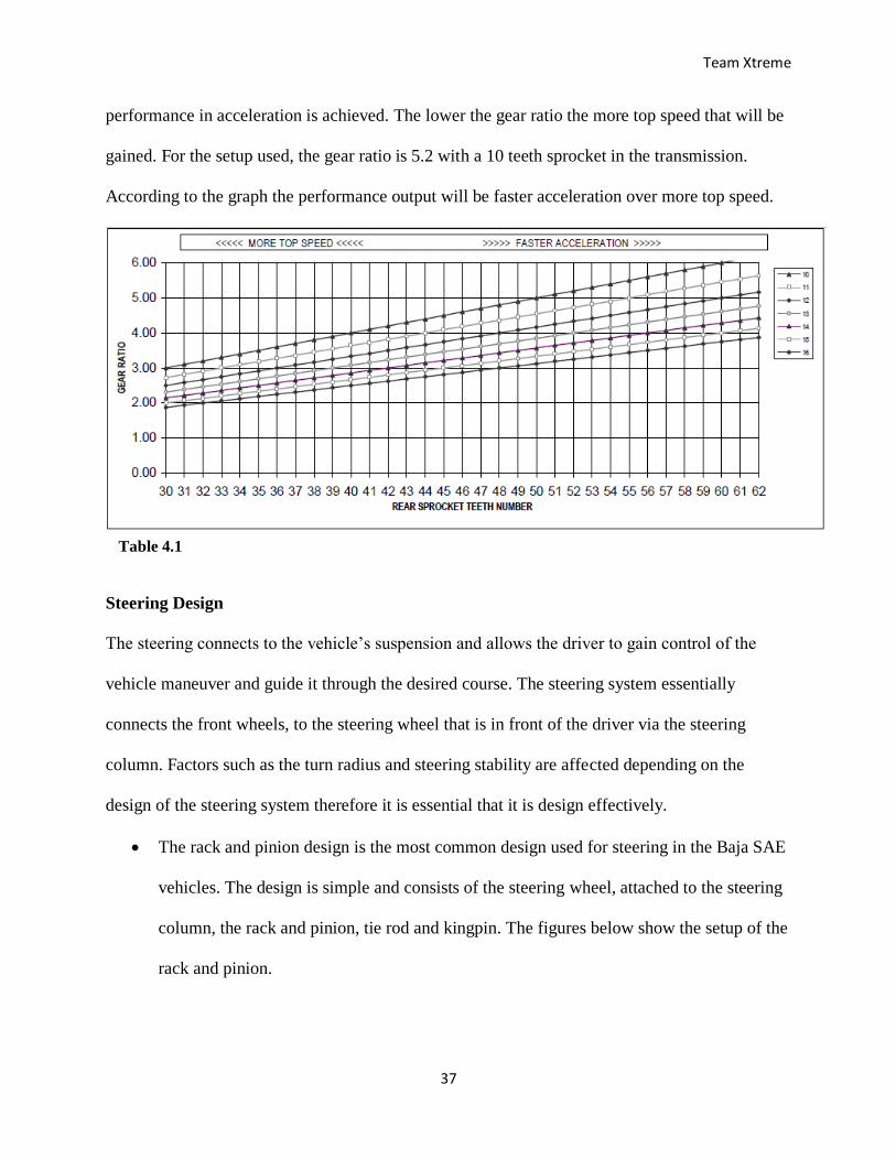
37
performance in acceleration is achieved. The lower the gear ratio the more top speed that will be
gained. For the setup used, the gear ratio is 5.2 with a 10 teeth sprocket in the transmission.
According to the graph the performance output will be faster acceleration over more top speed.
Steering Design
The steering connects to the vehicle’s suspension and allows the driver to gain control of the
vehicle maneuver and guide it through the desired course. The steering system essentially
connects the front wheels, to the steering wheel that is in front of the driver via the steering
column. Factors such as the turn radius and steering stability are affected depending on the
design of the steering system therefore it is essential that it is design effectively.
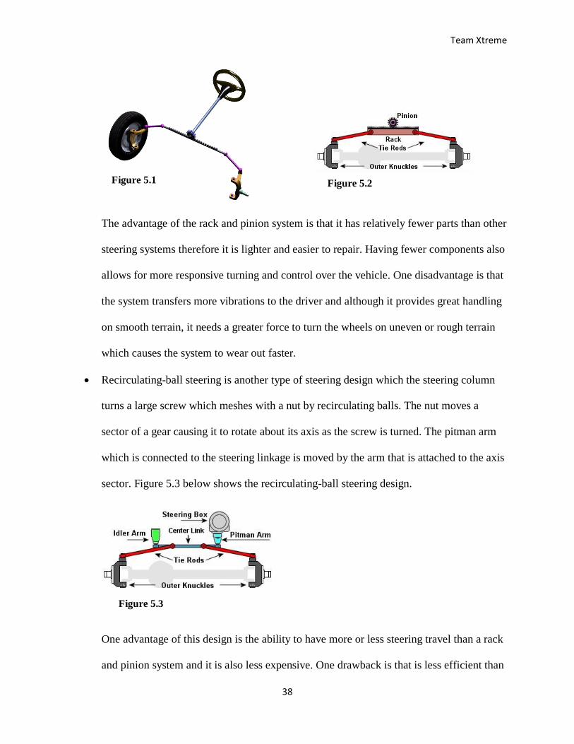
The rack and pinion design is the most common design used for steering in the Baja SAE
vehicles. The design is simple and consists of the steering wheel, attached to the steering
column, the rack and pinion, tie rod and kingpin. The figures below show the setup of the
rack and pinion.
Table 4.1
Team Xtreme
38
The advantage of the rack and pinion system is that it has relatively fewer parts than other
steering systems therefore it is lighter and easier to repair. Having fewer components also
allows for more responsive turning and control over the vehicle. One disadvantage is that
the system transfers more vibrations to the driver and although it provides great handling
on smooth terrain, it needs a greater force to turn the wheels on uneven or rough terrain
which causes the system to wear out faster.
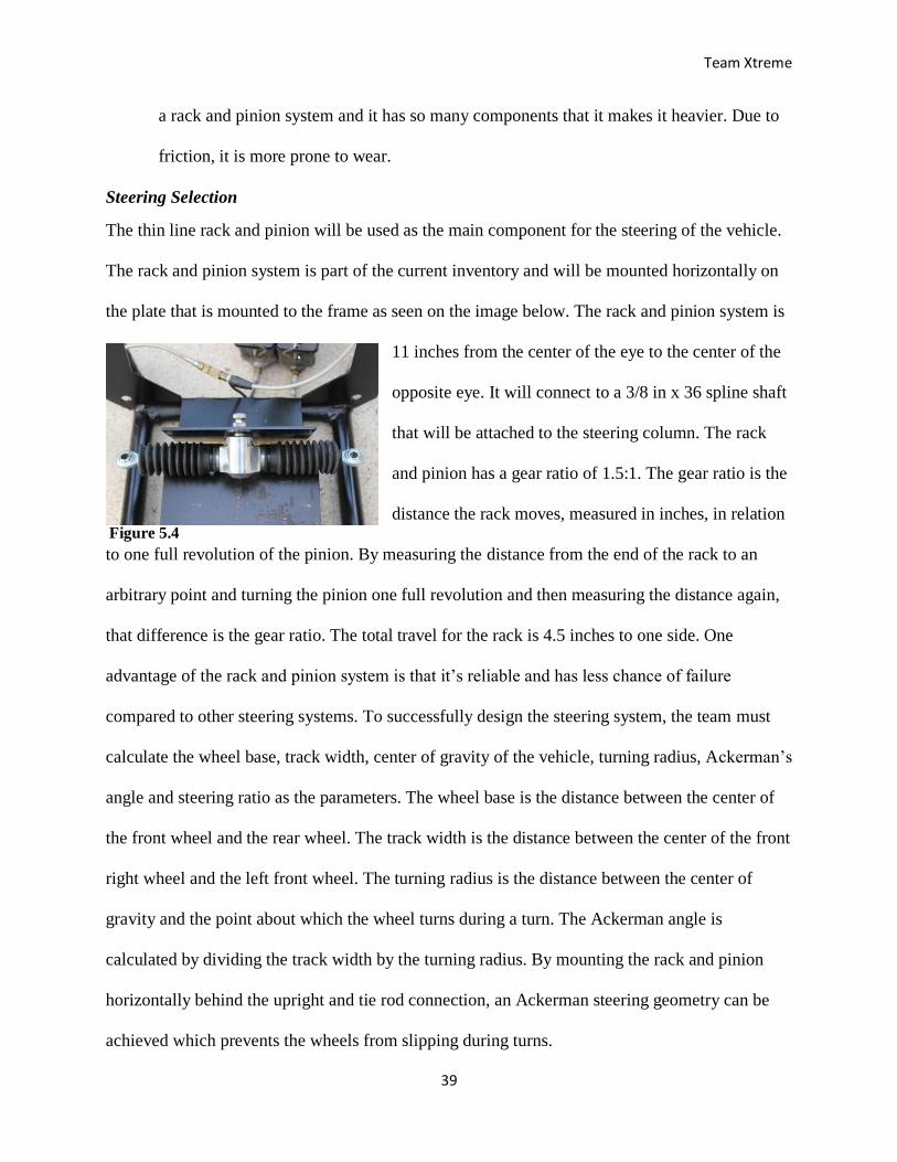
Recirculating-ball steering is another type of steering design which the steering column
turns a large screw which meshes with a nut by recirculating balls. The nut moves a
sector of a gear causing it to rotate about its axis as the screw is turned. The pitman arm
which is connected to the steering linkage is moved by the arm that is attached to the axis
sector. Figure 5.3 below shows the recirculating-ball steering design.
One advantage of this design is the ability to have more or less steering travel than a rack
and pinion system and it is also less expensive. One drawback is that is less efficient than
Figure 5.1
Figure 5.3
Figure 5.2
Team Xtreme
39
a rack and pinion system and it has so many components that it makes it heavier. Due to
friction, it is more prone to wear.
Steering Selection
The thin line rack and pinion will be used as the main component for the steering of the vehicle.
The rack and pinion system is part of the current inventory and will be mounted horizontally on
the plate that is mounted to the frame as seen on the image below. The rack and pinion system is
11 inches from the center of the eye to the center of the
opposite eye. It will connect to a 3/8 in x 36 spline shaft
that will be attached to the steering column. The rack
and pinion has a gear ratio of 1.5:1. The gear ratio is the
distance the rack moves, measured in inches, in relation
to one full revolution of the pinion. By measuring the distance from the end of the rack to an
arbitrary point and turning the pinion one full revolution and then measuring the distance again,
that difference is the gear ratio. The total travel for the rack is 4.5 inches to one side. One
advantage of the rack and pinion system is that it’s reliable and has less chance of failure
compared to other steering systems. To successfully design the steering system, the team must
calculate the wheel base, track width, center of gravity of the vehicle, turning radius, Ackerman’s
angle and steering ratio as the parameters. The wheel base is the distance between the center of
the front wheel and the rear wheel. The track width is the distance between the center of the front
right wheel and the left front wheel. The turning radius is the distance between the center of
gravity and the point about which the wheel turns during a turn. The Ackerman angle is
calculated by dividing the track width by the turning radius. By mounting the rack and pinion
horizontally behind the upright and tie rod connection, an Ackerman steering geometry can be
achieved which prevents the wheels from slipping during turns.
Figure 5.4
Team Xtreme
40
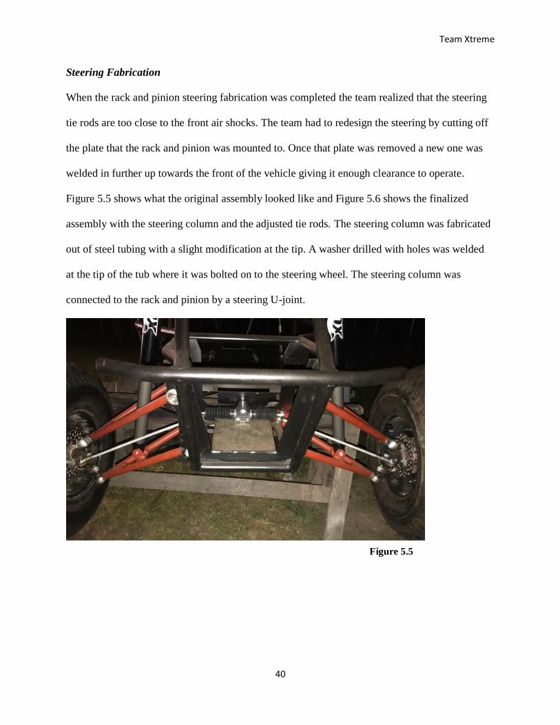
Steering Fabrication
When the rack and pinion steering fabrication was completed the team realized that the steering
tie rods are too close to the front air shocks. The team had to redesign the steering by cutting off
the plate that the rack and pinion was mounted to. Once that plate was removed a new one was
welded in further up towards the front of the vehicle giving it enough clearance to operate.
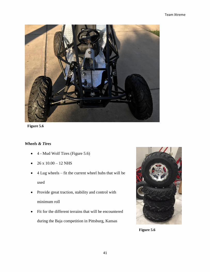
Figure 5.5 shows what the original assembly looked like and Figure 5.6 shows the finalized
assembly with the steering column and the adjusted tie rods. The steering column was fabricated
out of steel tubing with a slight modification at the tip. A washer drilled with holes was welded
at the tip of the tub where it was bolted on to the steering wheel. The steering column was
connected to the rack and pinion by a steering U-joint.
Figure 5.5
Team Xtreme
41
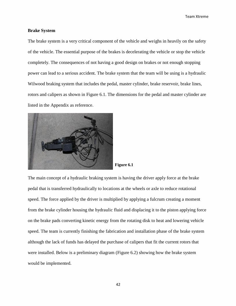
Wheels & Tires
4 - Mud Wolf Tires (Figure 5.6)
26 x 10.00 – 12 NHS
4 Lug wheels – fit the current wheel hubs that will be
used
Provide great traction, stability and control with
minimum roll
Fit for the different terrains that will be encountered
during the Baja competition in Pittsburg, Kansas
Figure 5.6
Figure 5.6
Team Xtreme
42
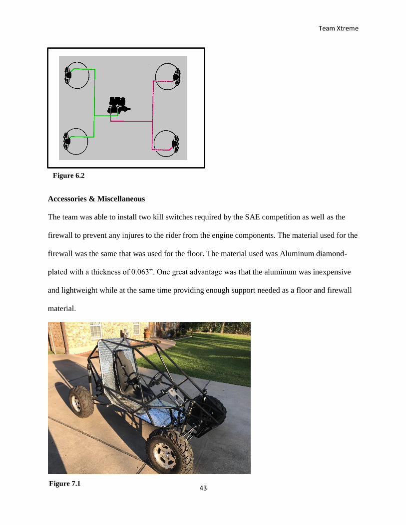
Brake System
The brake system is a very critical component of the vehicle and weighs in heavily on the safety
of the vehicle. The essential purpose of the brakes is decelerating the vehicle or stop the vehicle
completely. The consequences of not having a good design on brakes or not enough stopping
power can lead to a serious accident. The brake system that the team will be using is a hydraulic
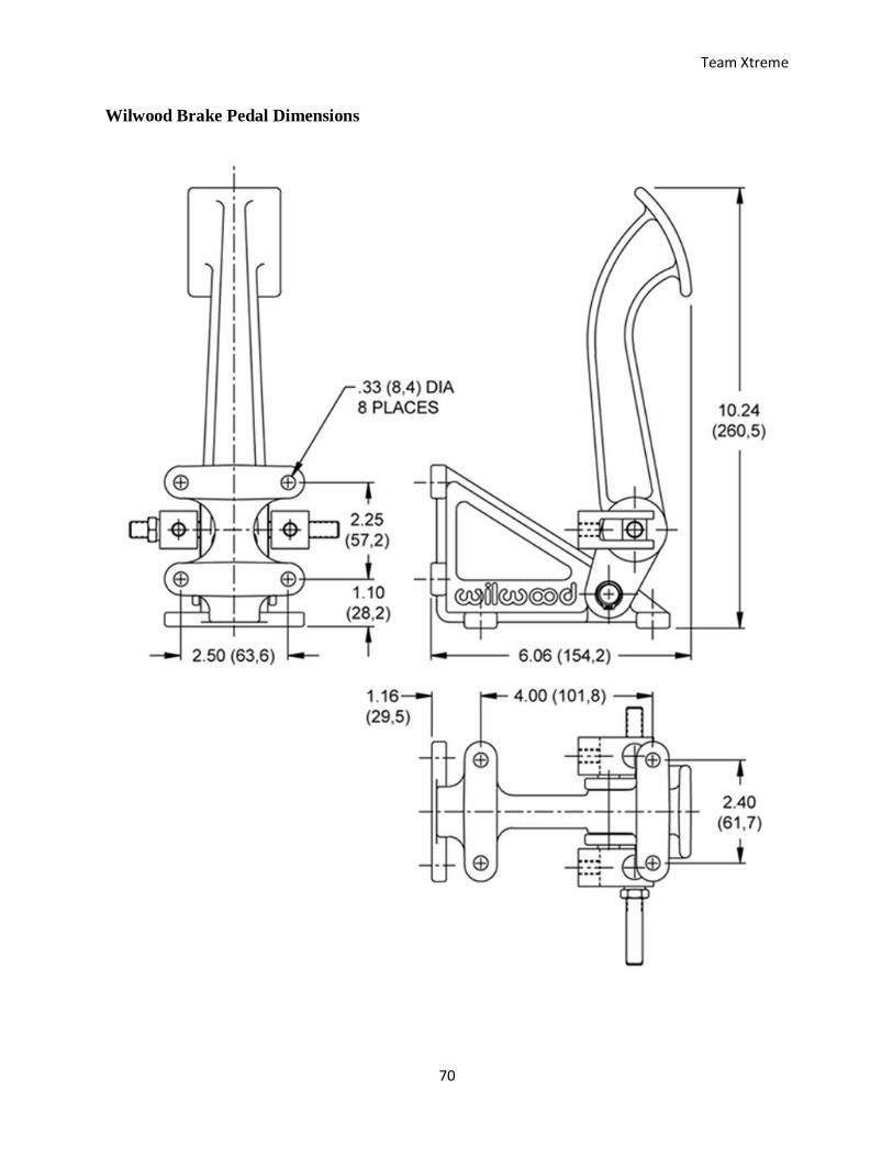
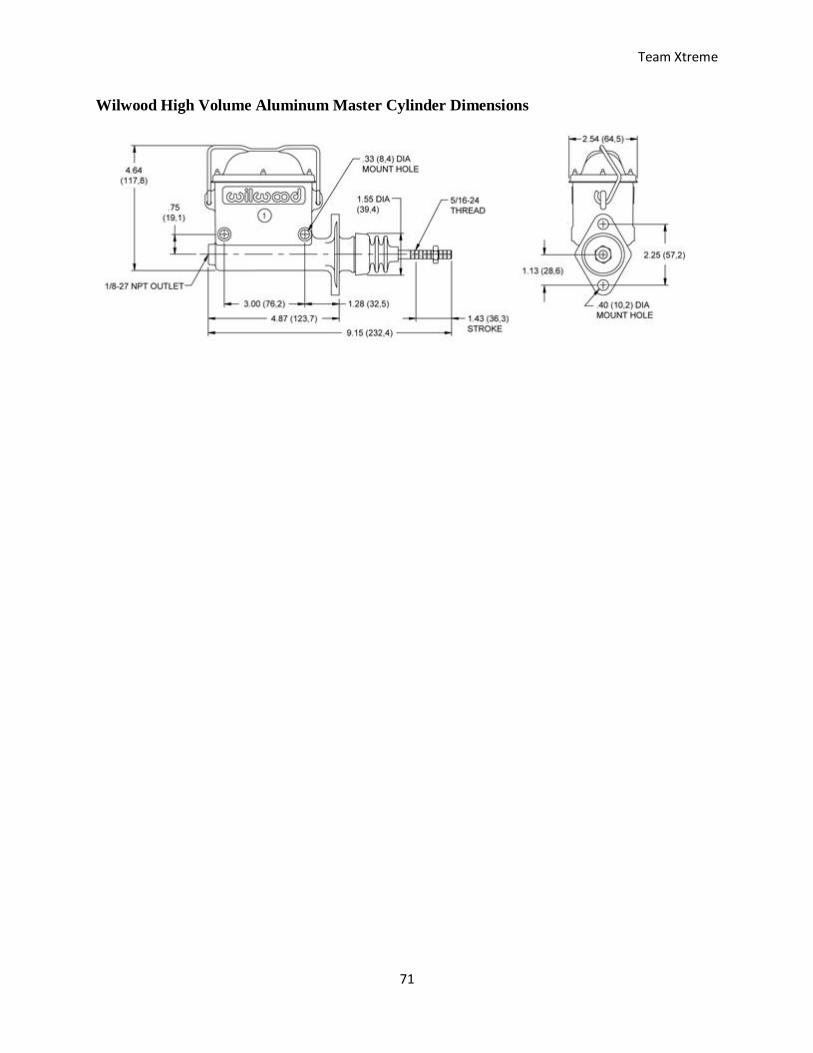
Wilwood braking system that includes the pedal, master cylinder, brake reservoir, brake lines,
rotors and calipers as shown in Figure 6.1. The dimensions for the pedal and master cylinder are
listed in the Appendix as reference.
The main concept of a hydraulic braking system is having the driver apply force at the brake
pedal that is transferred hydraulically to locations at the wheels or axle to reduce rotational
speed. The force applied by the driver is multiplied by applying a fulcrum creating a moment
from the brake cylinder housing the hydraulic fluid and displacing it to the piston applying force
on the brake pads converting kinetic energy from the rotating disk to heat and lowering vehicle
speed. The team is currently finishing the fabrication and installation phase of the brake system
although the lack of funds has delayed the purchase of calipers that fit the current rotors that
were installed. Below is a preliminary diagram (Figure 6.2) showing how the brake system
would be implemented.
Figure 6.1
Team Xtreme
43
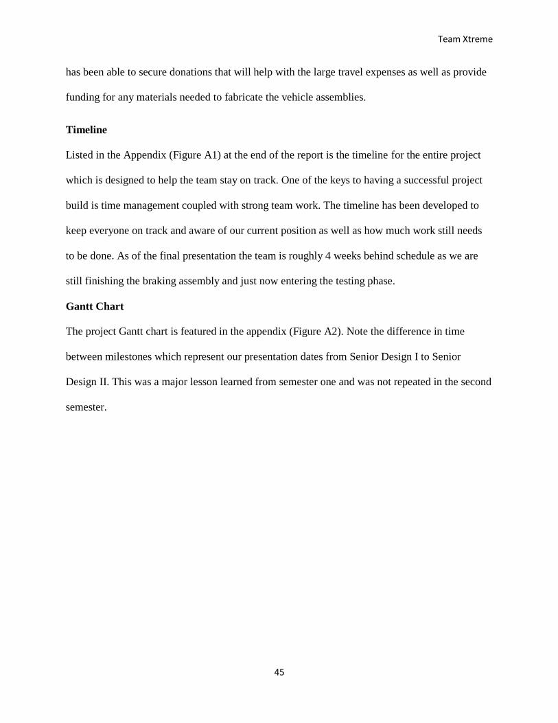
Accessories & Miscellaneous
The team was able to install two kill switches required by the SAE competition as well as the
firewall to prevent any injures to the rider from the engine components. The material used for the
firewall was the same that was used for the floor. The material used was Aluminum diamond-
plated with a thickness of 0.063”. One great advantage was that the aluminum was inexpensive
and lightweight while at the same time providing enough support needed as a floor and firewall
material.
Figure 6.2
Figure 7.1

Team Xtreme
44
Project Management
For Team Xtreme to successfully complete the project on time and meet all proposed deadlines
and goals certain constraints were laid out as the foundation of the project. The scope, time and
budget are the primary constraints of the project. In the initiation process, through planning,
execution, and closing of the project, the potential risks were identified, the work break down
structure was created and the timeline was generated to increase productivity and to allow the
team to successfully manage the project from start to finish.
Budget
After considering the donated parts listed in the Appendix (Figure A3) the highest costs for the
entire project include: the transmission, registration fees and the travel expenses for the 2017
Baja SAE competition in Kansas. The mitigation for these high costs consist of making
fundraising a weekly focus throughout the semester to acquire enough funds for the registration
fees. The team plans to use a members’ vehicle and borrow a trailer to reduce the cost of travel.
The team will also check online routinely for deals on lodging. Throughput the project the team
Component: Estimated Cost 9/15/16: Adjusted Cost 5/6/2017: Donated Purchased
Chassis $1,000 $100 * *
Suspension $2,000 $0 * *
Steering $650 $0 * *
Engine $250 $0
Transmission $1,000 $0 *
Brakes $400 $215 *
Tires and rims $900 $0 *
Seat $60 $0 *
Safety equipment $400 $250
Instrumentation/electrical $350 $0 *
Registration fees $1,250 $1,250
Travel & lodging $1,500 $1,500
Total: $9,760 $3,315
Contingency: $1,952 $332 $0 $0
Total with contingency: $11,712 $3,647 $4,965 $1,100
Table 6.1
Team Xtreme
45
has been able to secure donations that will help with the large travel expenses as well as provide
funding for any materials needed to fabricate the vehicle assemblies.
Timeline
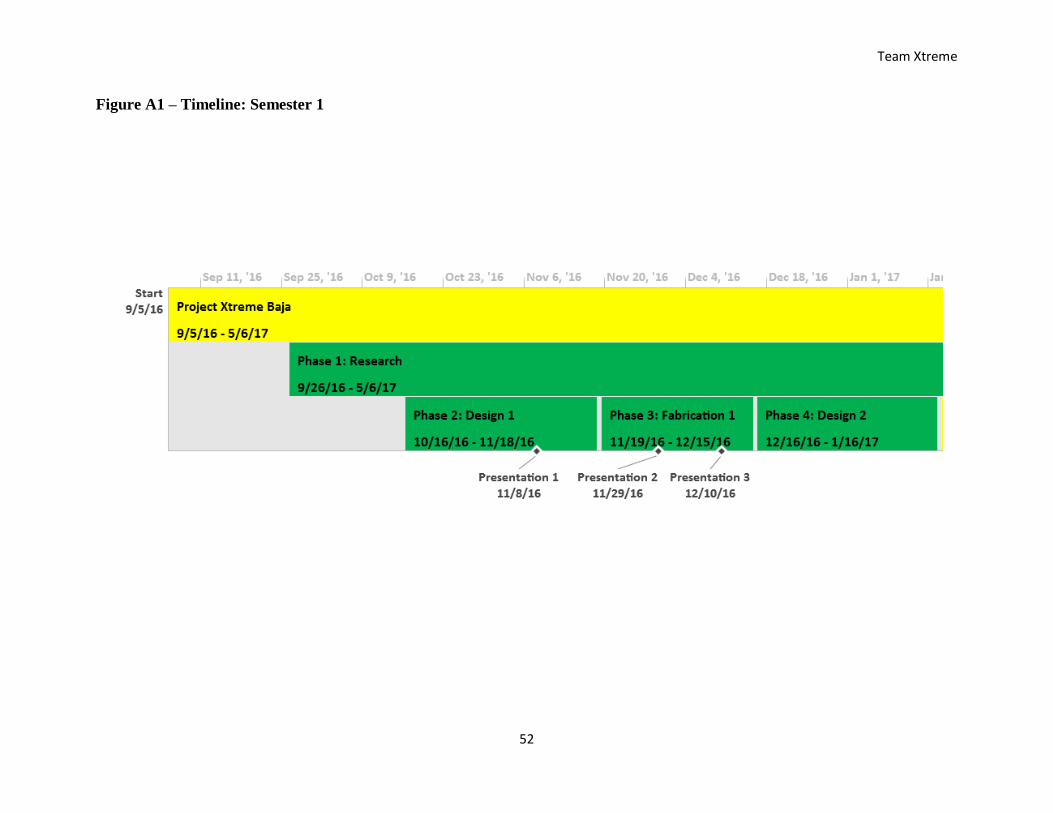
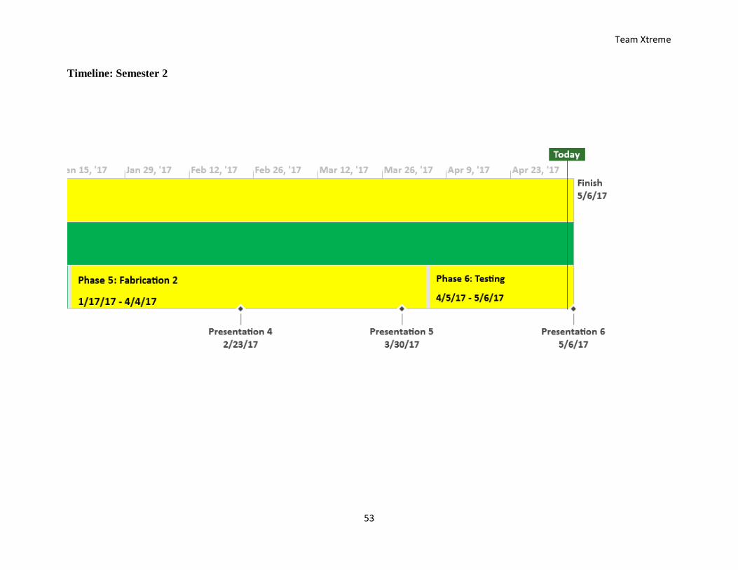
Listed in the Appendix (Figure A1) at the end of the report is the timeline for the entire project
which is designed to help the team stay on track. One of the keys to having a successful project
build is time management coupled with strong team work. The timeline has been developed to
keep everyone on track and aware of our current position as well as how much work still needs
to be done. As of the final presentation the team is roughly 4 weeks behind schedule as we are
still finishing the braking assembly and just now entering the testing phase.
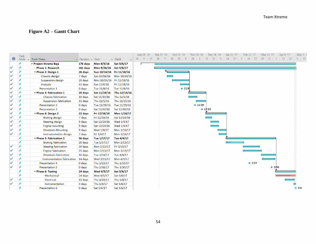
Gantt Chart
The project Gantt chart is featured in the appendix (Figure A2). Note the difference in time
between milestones which represent our presentation dates from Senior Design I to Senior
Design II. This was a major lesson learned from semester one and was not repeated in the second
semester.

Team Xtreme
46
Work Breakdown Structure (WBS)
The Work Breakdown Structure above shows an exploded view of the entire project as well as
the tasks the team has completed, the tasks that are in progress and the tasks that have not been
started. As of presentation 6 the team has finished fabricating the suspension, steering,
instrumentation, and powertrain assemblies. We are lacking the funds to complete the braking
assembly and the vehicle needs brakes to complete the testing phase for the mechanical
components.
Figure 6.2
Team Xtreme
47
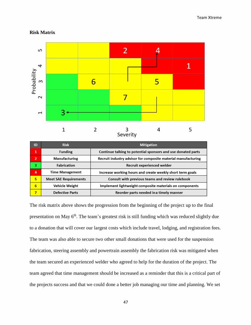
Risk Matrix
The risk matrix above shows the progression from the beginning of the project up to the final
presentation on May 6th. The team’s greatest risk is still funding which was reduced slightly due
to a donation that will cover our largest costs which include travel, lodging, and registration fees.
The team was also able to secure two other small donations that were used for the suspension
fabrication, steering assembly and powertrain assembly the fabrication risk was mitigated when
the team secured an experienced welder who agreed to help for the duration of the project. The
team agreed that time management should be increased as a reminder that this is a critical part of
the projects success and that we could done a better job managing our time and planning. We set
Team Xtreme
48
weekly goals and increased the number of hours we worked on the project to improve our
productivity. Two new risks have been added to the risk matrix since the beginning of the project
the first one is the vehicle weight. The mitigation for this risk is to use light weight components
as much as possible to meet our deliverable of fabricating a vehicle with a curb weight under 400
pounds. The second risk that was added is the possibility that some of the parts we acquired from
Baja Brigade could be defective. The parts we acquired have been sitting around for over a year
and may not be in working condition any longer. Our mitigation for this risk is to find out these
parts can be used as soon as possible and if they can’t we must reorder them in a timely fashion.
Team Xtreme
49
References
"BAJA Automotive Enthusiasts." Baja Tutor Knowledge Base for BAJA Automotive Enthusiasts.
Web. 15 Oct. 2016. <http://bajatutor.org/>.
"Baja SAE Kansas." - Baja SAE. Web. 1 Sept. 2016. <http://students.sae.org/cds/bajasae/east/>.
CADmantra Technologies Follow. "Chassis Design for Baja SAE." Chassis Design for Baja
SAE. 26 Sept. 2015. Web. 26 Sept. 2016. <http://www.slideshare.net/bholapatel/chassis-
design-for-baja-sae>.
"Intrax Racing." Intrax Racing. Web. 20 Oct. 2016. <http://en.intraxracing.nl/techniek/camber,-
caster,-toe-intoe-out/>.
Isaac-Lowry, By Jacob. "Suspension Design: Types of Suspensions - Automotive Articles .com
Magazine." Suspension Design: Types of Suspensions - Automotive Articles .com
Magazine. Web. 6 Sept. 2016.
<http://www.automotivearticles.com/Suspension_Design_Types_of_Suspensions.shtml>.
Michael, John. "The Advantages of Rack & Pinion Steering." EHow. Demand Media. Web. 01
Nov. 2016. <http://www.ehow.com/list_6102863_advantages-rack-pinion-
steering.html>.
"Rack and Pinion Steering System | Advantages | Application." Mechanical Engineering World.
Web. 1 Nov. 2016. <http://www.mechengg.net/2015/03/rack-and-pinion-steering-
system.html>.
"Recirculating Ball." Wikipedia. Wikimedia Foundation. Web. 07 Nov. 2016.
<https://en.wikipedia.org/wiki/Recirculating_ball>.
"SAE Baja Car." MiniBuggyNet The Ultimate OffRoad Buggy Community RSS. Web. 20 Oct.
2016. <http://www.minibuggy.net/forum/show-off-your-toys-here/6776-sae-baja-car-
7.html>.

Team Xtreme
50
Singh, Avinash. Off-Road Suspension Design. 2016. Amazon Inc.
"Trailing Arm or Semi Trailing Arm." Official Baja SAE Forums. Web. 22 Sept. 2016.
<http://forums.bajasae.net/forum/trailing-arm-or-semi-trailing-arm_topic1834.html>.
Team Xtreme
51
APPENDIX
Team Xtreme
52
Figure A1 – Timeline: Semester 1
Team Xtreme
53
Timeline: Semester 2
Team Xtreme
54
Figure A2 – Gantt Chart
Team Xtreme
55
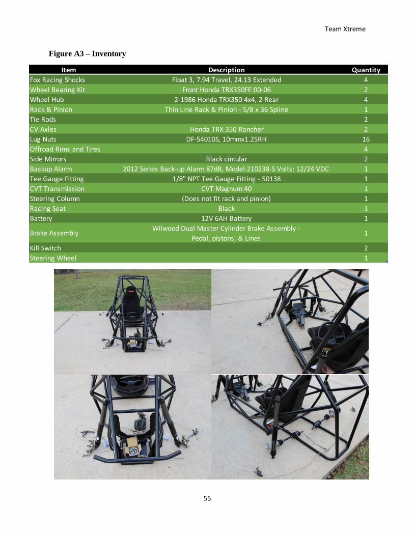
Figure A3 – Inventory
Item Description Quantity
Fox Racing Shocks Float 3, 7.94 Travel, 24.13 Extended 4
Wheel Bearing Kit Front Honda TRX350FE 00-06 2
Wheel Hub 2-1986 Honda TRX350 4x4, 2 Rear 4
Rack & Pinion Thin Line Rack & Pinion - 5/8 x 36 Spline 1
Tie Rods 2
CV Axles Honda TRX 350 Rancher 2
Lug Nuts DF-54010S, 10mmx1.25RH 16
Offroad Rims and Tires 4
Side Mirrors Black circular 2
Backup Alarm 2012 Series Back-up Alarm 87dB, Model:210238-S Volts: 12/24 VDC 1
Tee Gauge Fitting 1/8" NPT Tee Gauge Fitting - 50138 1
CVT Transmission CVT Magnum 40 1
Steering Column (Does not fit rack and pinion) 1
Racing Seat Black 1
Battery 12V 6AH Battery 1
Brake AssemblyWilwood Dual Master Cylinder Brake Assembly -
Pedal, pistons, & Lines1
Kill Switch 2
Steering Wheel 1
Team Xtreme
56
Figure A4 - Examples of Failing Welds: Sample #1 (Destructive Testing)
http://students.sae.org/cds/bajasae/rules
Team Xtreme
57
Figure A5 - Examples of Failing Welds: Sample #2 (Destructive Inspection)
http://students.sae.org/cds/bajasae/rules
Team Xtreme
58
Figure A6 - Examples of Passing Welds
http://students.sae.org/cds/bajasae/rules
Team Xtreme
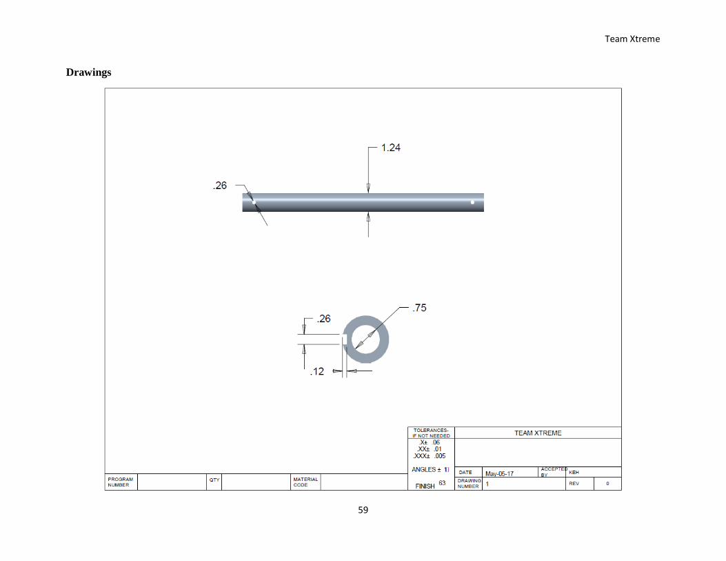
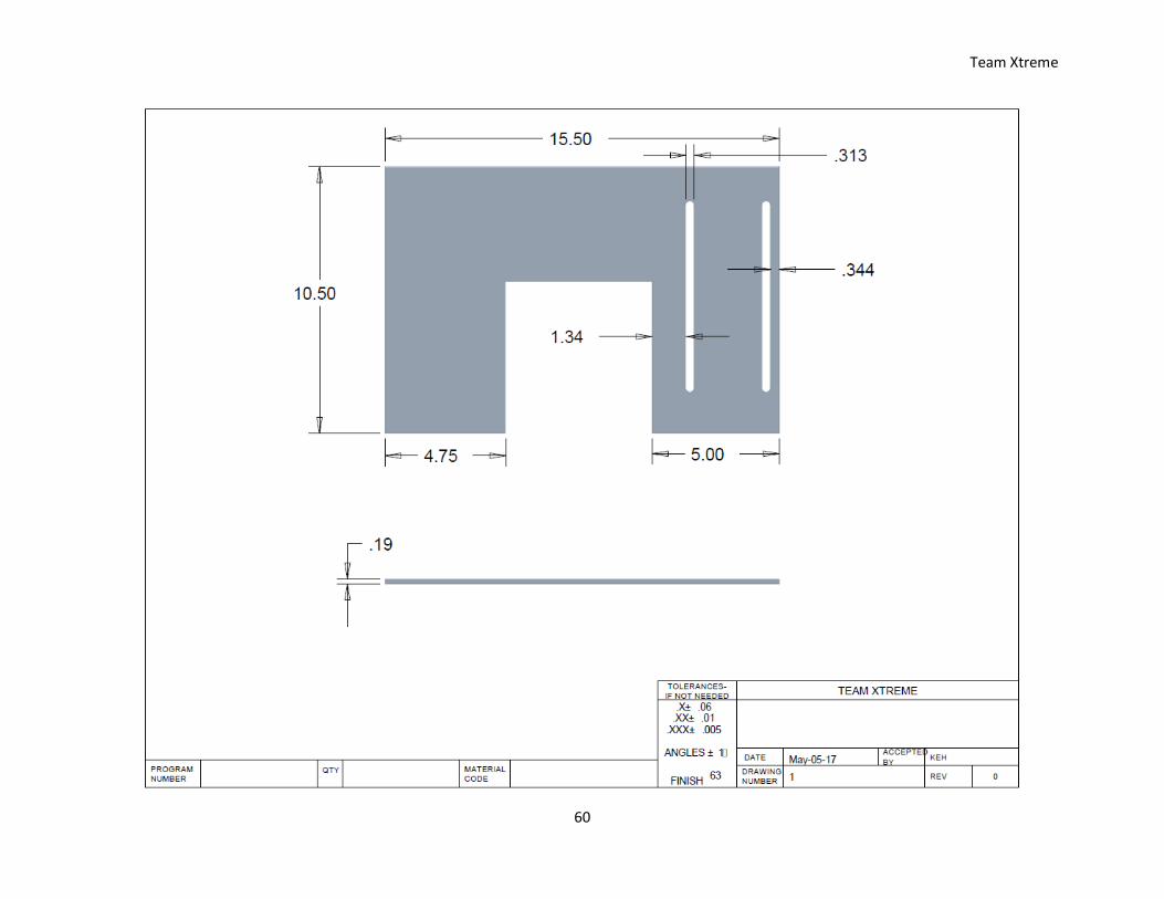
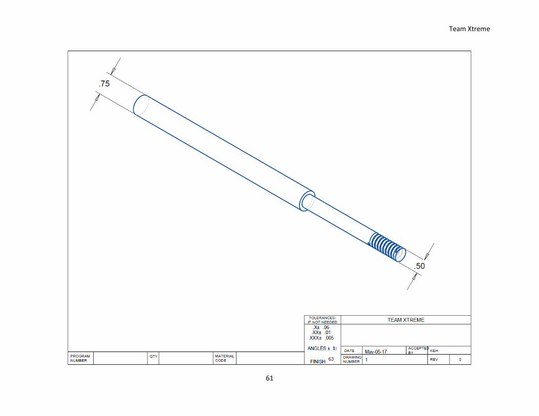
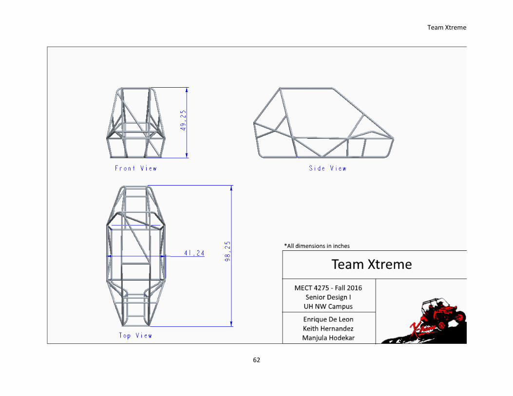
59
Drawings
Team Xtreme
60
Team Xtreme
61
Team Xtreme
62
Team Xtreme
63
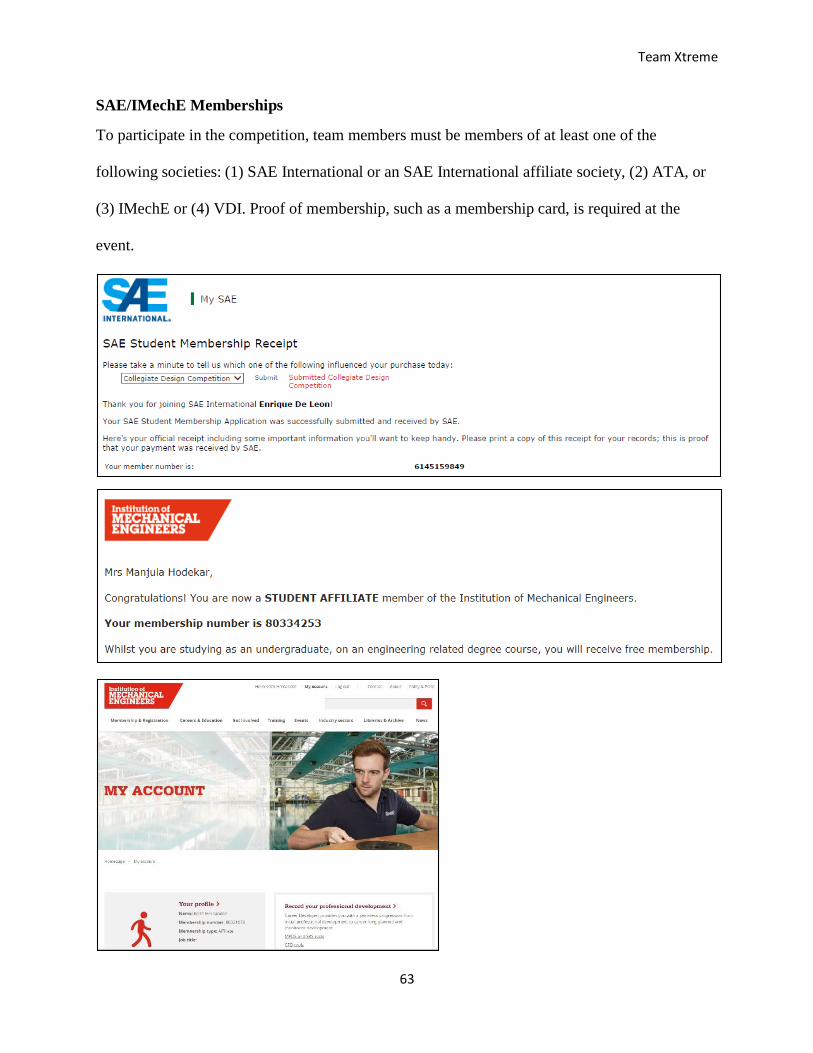
SAE/IMechE Memberships
To participate in the competition, team members must be members of at least one of the
following societies: (1) SAE International or an SAE International affiliate society, (2) ATA, or
(3) IMechE or (4) VDI. Proof of membership, such as a membership card, is required at the
event.
Team Xtreme
64
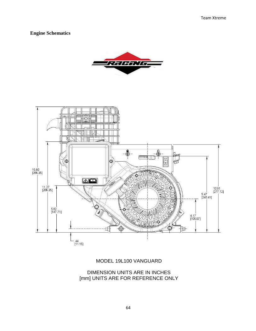
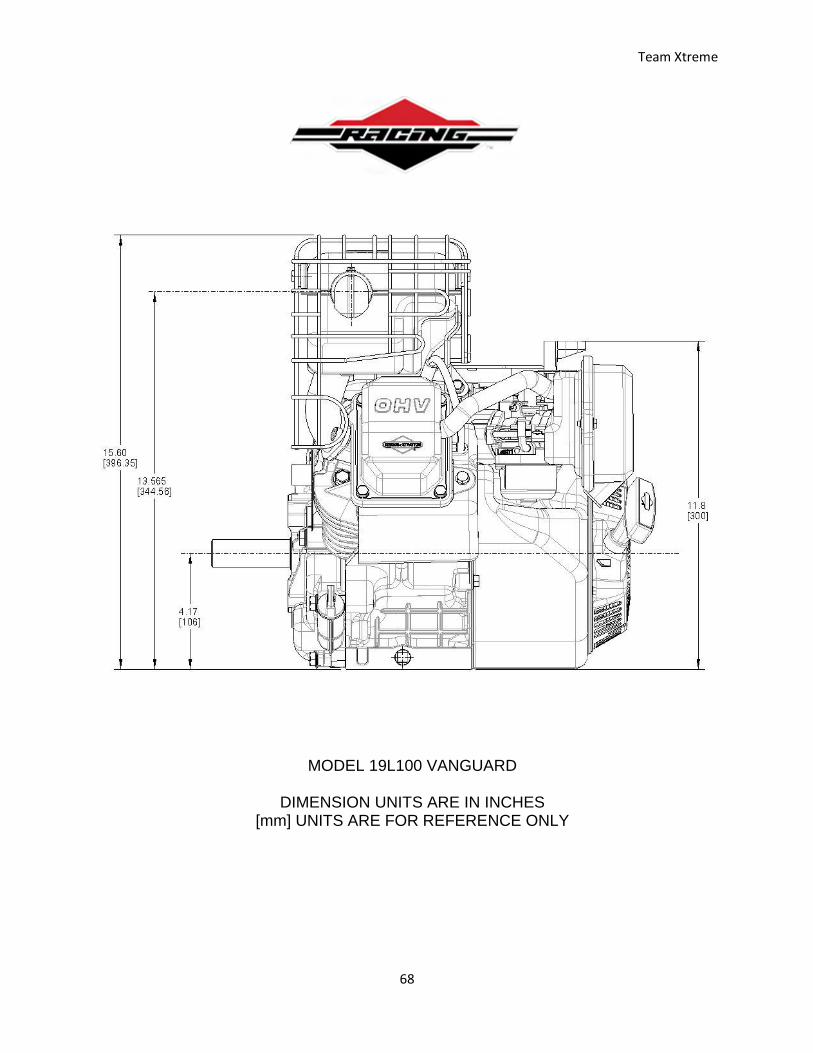
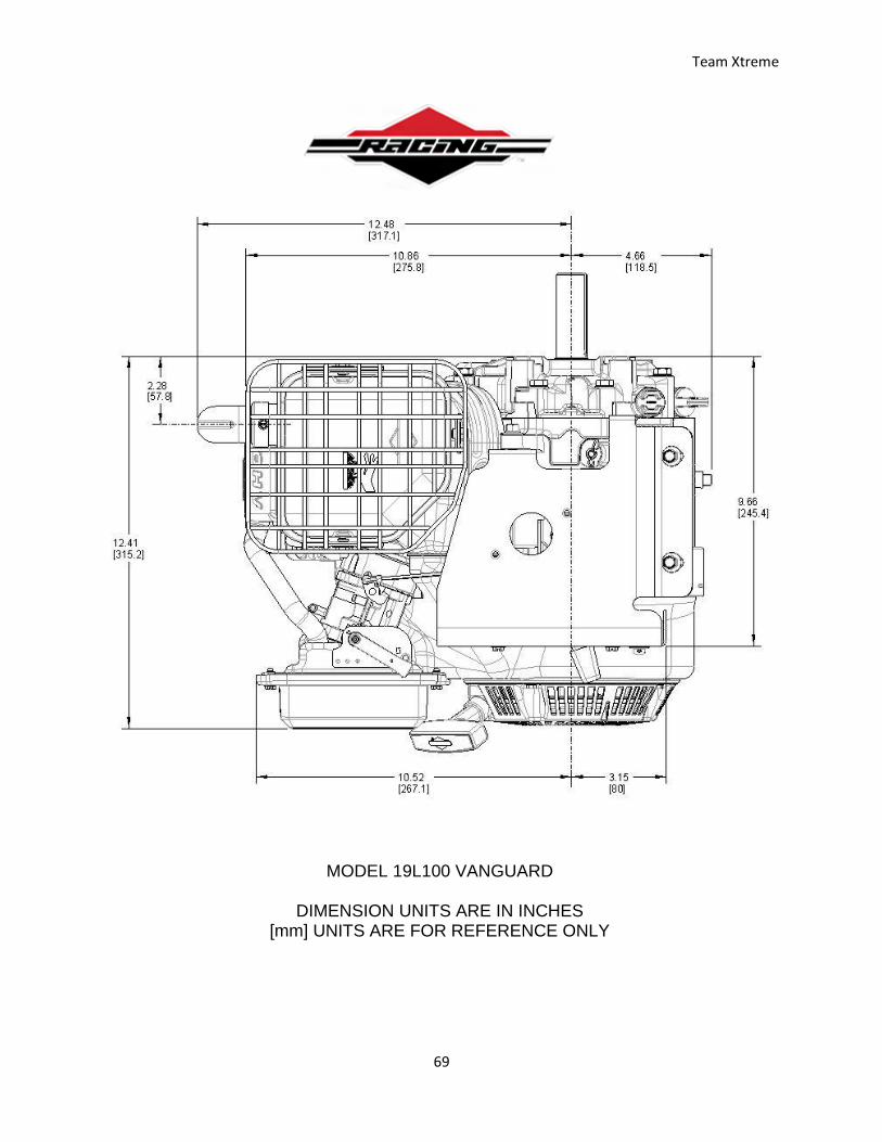
Engine Schematics
MODEL 19L100 VANGUARD
DIMENSION UNITS ARE IN INCHES [mm] UNITS ARE FOR REFERENCE ONLY
Team Xtreme
65
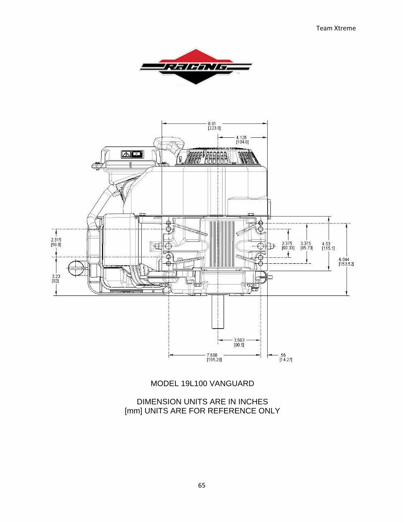
MODEL 19L100 VANGUARD
DIMENSION UNITS ARE IN INCHES [mm] UNITS ARE FOR REFERENCE ONLY
Team Xtreme
66
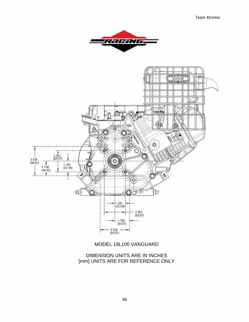
MODEL 19L100 VANGUARD
DIMENSION UNITS ARE IN INCHES [mm] UNITS ARE FOR REFERENCE ONLY
Team Xtreme
67
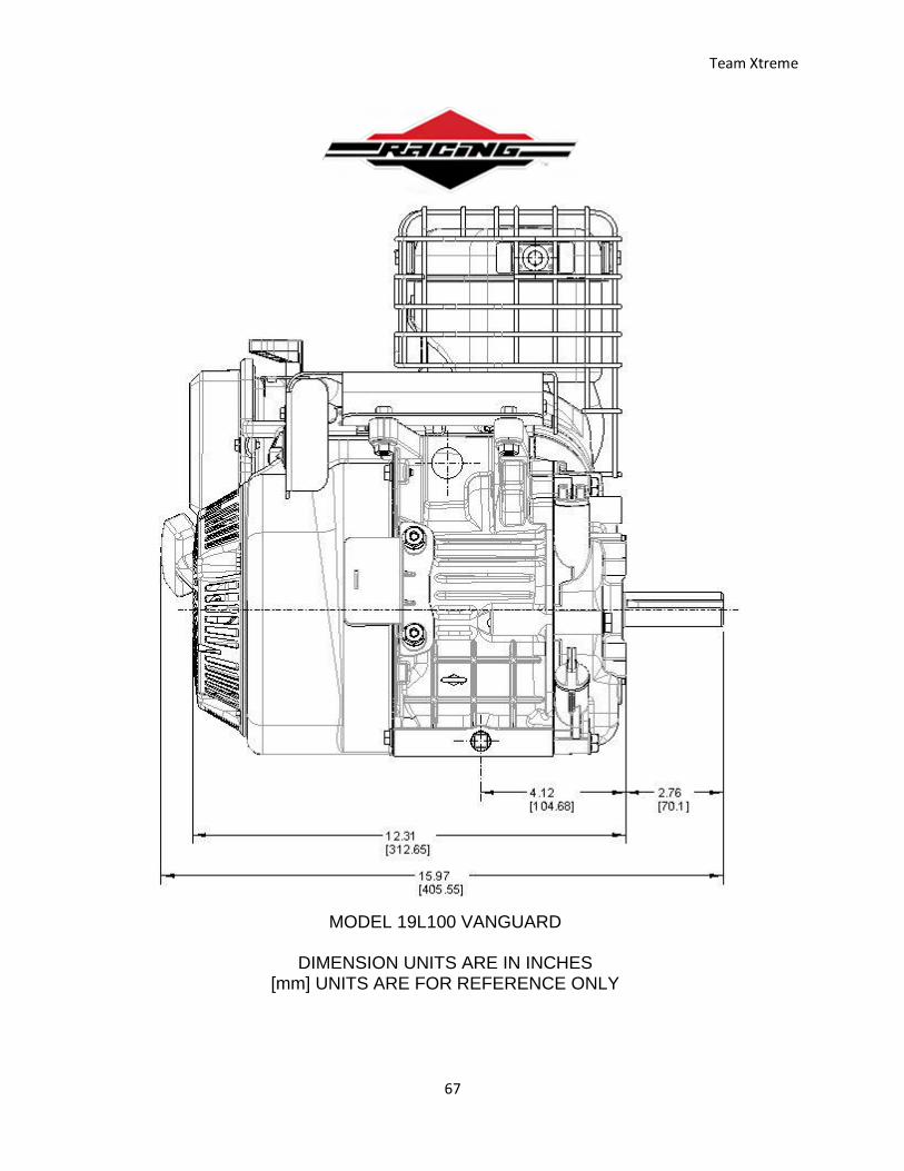
MODEL 19L100 VANGUARD
DIMENSION UNITS ARE IN INCHES [mm] UNITS ARE FOR REFERENCE ONLY
Team Xtreme
68
MODEL 19L100 VANGUARD
DIMENSION UNITS ARE IN INCHES [mm] UNITS ARE FOR REFERENCE ONLY
Team Xtreme
69
MODEL 19L100 VANGUARD
DIMENSION UNITS ARE IN INCHES [mm] UNITS ARE FOR REFERENCE ONLY
Team Xtreme
70
Wilwood Brake Pedal Dimensions
Team Xtreme
71
Wilwood High Volume Aluminum Master Cylinder Dimensions
Team Xtreme
72
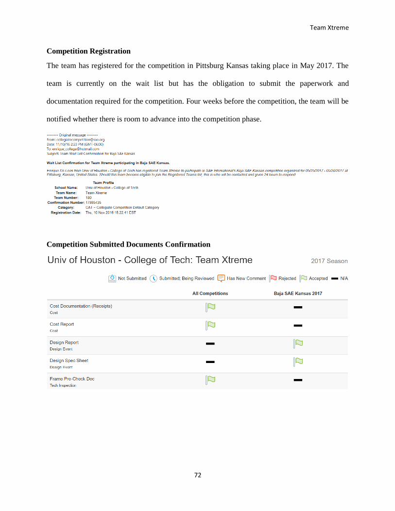
Competition Registration
The team has registered for the competition in Pittsburg Kansas taking place in May 2017. The
team is currently on the wait list but has the obligation to submit the paperwork and
documentation required for the competition. Four weeks before the competition, the team will be
notified whether there is room to advance into the competition phase.
Competition Submitted Documents Confirmation

Team Xtreme
73
Professional Development Hours (PDH)
Team Xtreme
74
1/9 PDH hours
Manjula Hodekar
Wood Co USA Visit
The “WOODCO USA” is a small manufacturing company located in Houston TX. This is a
private business started in 1958 by Wood George and the current owner is Ashley George. We
learned about routing; the process to produce the machined parts from the raw materials. Step by
step instructions to make the parts to the measurements and specifications provided in the
drawings and documents. There are various manufacturing equipment in the Woodco USA,
including load test machine (Big George), overhead cranes, liquid penetrate test (LPT) machine,
mandrill, drilling machine, welding machines, sub arc machines, hydrostatic testing, pressure
testing, CNC machines, Lathe machines, ultrasonic test machines etc. The customized Load test
machine capacity is up to 900 tons.
Date: 09/14/2016

Team Xtreme
75
2/9 PDH hours
Manjula Hodekar
Mesh Sensitivity/Convergence Analysis
Objective:
The purpose of this document is to examine the procedure of running a mesh sensitivity analysis
of a static structure FEA using Creo (P-method) and ANSYS Workbench (H-method).
Ran a mesh sensitivity analysis on a flat bar with a shoulder fillet using PTC Creo (P-method and
ANSYS Workbench (H-method) to achieve convergence on the normal stress due to axial
loading. Running a mesh sensitivity analysis ensures the results are independent of the mesh
refinement are accurate.
Presented by: Ahmed Hassanin
Date: 11/5/2016
Team Xtreme
76
3/9 PDH hours
Manjula Hodekar
Fatigue Analysis and Design Optimization
Objective:
The purpose of this workshop is to examine the procedure of running fatigue analysis and then
optimizing driving parameters to achieve higher number of cycles before failure. Understand the
different failure criteria. Learn optimization techniques.
Optimized a flat bar with a shoulder fillet using ANSYS Workbench and achieved a higher life
based on fatigue analysis.
Presented by: Ahmed Hassanin
Date: 11/12/2016
Team Xtreme
77
4/9 PDH hours
Manjula Hodekar
Houstex exhibition including manufacturing, research & development, lathe & terming
machines, drilling, welding, heat treatment, measurement tests, CAD/CAM Software and so on.
Many companies based outside of Texas. All these businesses are introducing their new products
and services at Houstex. For example: THERMTECH company based in WI, presenting their
heat treatment services for manufacturers. This company can do any type heat treatment for any
products. THERMTECH specialized in heat treating the costing and forgings.
Date: 03/02/2017
Location: George R. Brown Convention Center, Houston, Texas.
Team Xtreme
78
5/9 PDH hours
Manjula Hodekar
Team Xtreme
79
6/9 PDH hours
Manjula Hodekar
Team Xtreme
80
7/9 PDH hours
Manjula Hodekar
Team Xtreme
81
8/9 PDH hours
Manjula Hodekar
Team Xtreme
82
9/9 PDH hours
Manjula Hodekar

Team Xtreme
83
1/9 PDH hours
Keith Hernandez
On October 5th 2016 I attended the Internet of Things Unlimited Opportunities seminar with
speaker Mr. Jeremy Jones. The internet of Things is basically a network of connected devices
you can interact with. Mr. Jones stated than in 4 years by 2020 there will be 50 billion connected
devices. The process starts with a sensor on a piece of equipment such as a garage door this
sensor can detect if the door is open or closed. The data is sent from the sensor to an edge node
that collects the data the sensor is supposed to read. Then from the edge node the data collected
is transferred to a gateway which speaks to the cloud were the data is manipulated and sent to a
mobile device of the users’ choice. So, if you were to forget to close your garage door for
whatever reason you would be alerted on your phone and can close the door from your mobile
device. Mr. Jones also stated that the IoT has its biggest impact on the service industry however
85% of the equipment used in the US service industry is not equipped to handle the IoT
applications.
Mr. Jones is currently employed by Comfort Systems USA. The way Comfort Systems USA
uses the IoT is they have pressure, temperature, and voltage sensors attached to AC units to make
the AC technicians job easier. Instead of going on the roof where the unit is located, in 100-
degree weather and working on it. Technicians can now receive real time data about the
pressure, temperature and voltage of the AC unit on their mobile device. This allows them to
diagnose the problem without having to go on the roof in the heat and work on it. This method
also helps to prevent a failure before it happens so they fix AC units before they break.
Team Xtreme
84
2/9 PDH hours
Keith Hernandez
Team Xtreme
85
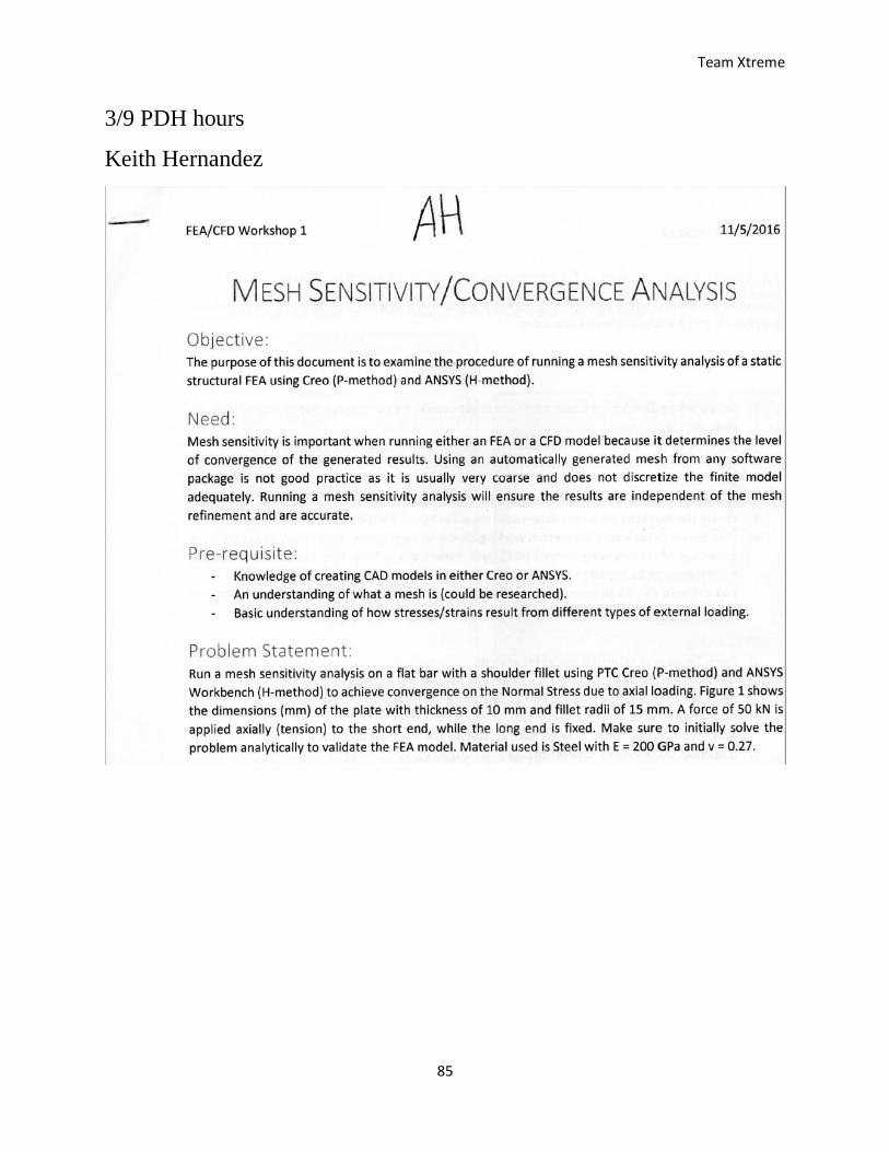
3/9 PDH hours
Keith Hernandez
Team Xtreme
86
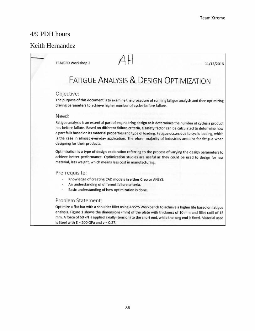
4/9 PDH hours
Keith Hernandez
Team Xtreme
87
5/9 PDH hours
Keith Hernandez
Personal Development Hour number five was used to watch the Going Nuclear debate held at the
UH main campus. I watched the live stream of the entire debate on Facebook live. The debate
had three different experts that were discussing the future of the worlds energy needs. In the end
two agreed on the use of nuclear power as well as wind, water, solar and other sources that
generate power to diversify the production of the worlds energy. One of the experts did not want
anything to do with nuclear energy and believed the energy concerns could be solved using all
renewable sources. His strategies for cooling buildings with ice and coils that the air circulates
through and solving the energy crisis were interesting. The final speaker was a woman who
talked about the impact of nuclear energy on society. She was from Singapore and spoke about
the pros and cons of nuclear energy. An interesting debate to listen to and see what the future is
faced with as far as energy production and consumption.
Team Xtreme
88
6/9 PDH hours
Keith Hernandez
Team Xtreme
89
7/9 PDH hours
Keith Hernandez
Team Xtreme
90
8/9 PDH hours
Keith Hernandez
Team Xtreme
91
9/9 PDH hours
Keith Hernandez
Team Xtreme
92
1/9 PDH hours
Enrique De Leon

Team Xtreme
93
2/9 PDH hours
Enrique De Leon

Team Xtreme
94
3/9 PDH hours
Enrique De Leon
Team Xtreme
95
4/9 PDH hours
Enrique De Leon
Team Xtreme
96
5/9 PDH hours
Enrique De Leon
Team Xtreme
97
6/9 PDH hours
Enrique De Leon
Team Xtreme
98
7/9 PDH hours
Enrique De Leon
Team Xtreme
99
8/9 PDH hours
Enrique De Leon
Team Xtreme
100
9/9 PDH hours
Enrique De Leon
Team Xtreme
101
Community Outreach Hours
Team Xtreme
102
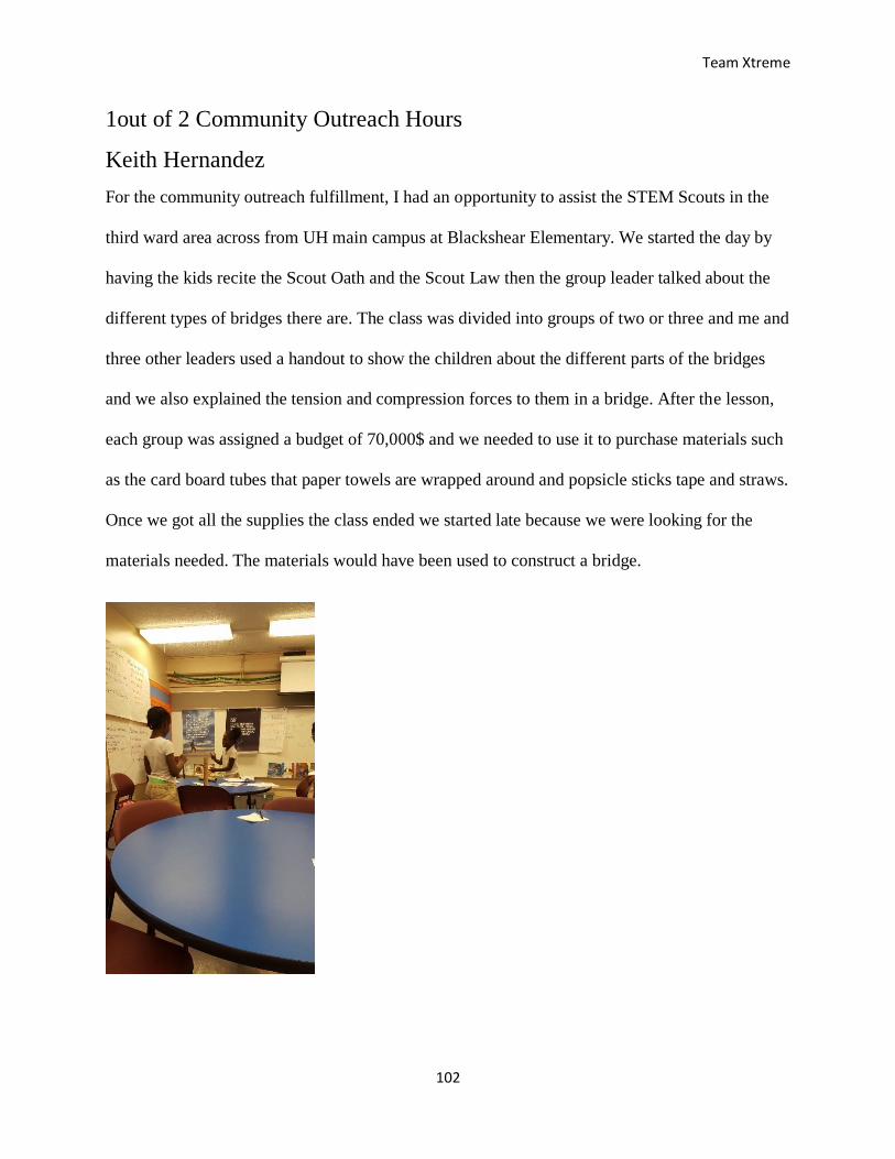
1out of 2 Community Outreach Hours
Keith Hernandez
For the community outreach fulfillment, I had an opportunity to assist the STEM Scouts in the
third ward area across from UH main campus at Blackshear Elementary. We started the day by
having the kids recite the Scout Oath and the Scout Law then the group leader talked about the
different types of bridges there are. The class was divided into groups of two or three and me and
three other leaders used a handout to show the children about the different parts of the bridges
and we also explained the tension and compression forces to them in a bridge. After the lesson,
each group was assigned a budget of 70,000$ and we needed to use it to purchase materials such
as the card board tubes that paper towels are wrapped around and popsicle sticks tape and straws.
Once we got all the supplies the class ended we started late because we were looking for the
materials needed. The materials would have been used to construct a bridge.
Team Xtreme
103
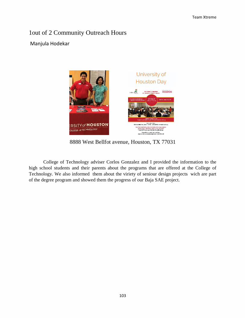
1out of 2 Community Outreach Hours
Manjula Hodekar
8888 West Bellfot avenue, Houston, TX 77031
College of Technology adviser Corlos Gonzalez and I provided the information to the
high school students and their parents about the programs that are offered at the College of
Technology. We also informed them about the viriety of seniour design projects wich are part
of the degree program and showed them the progress of our Baja SAE project.
Team Xtreme
104
Sponsorship Brochure