TEAC A 6100 6300 sm - Internet Archive
112
mmm | — | — — HI " “IP! • ~~ ...... ^ : A WM SaS i if’ . .. $ */ ». o o o * * * "" iXSSBM - / .^v^llS^S PMzM' "-®Si ///^ M ;;,.. . . Hi Hip i|§|i| %
Transcript of TEAC A 6100 6300 sm - Internet Archive

mmm
| — | — — HI
■"■“IP! • ~~ ......
^ : A WM SaS i if’ . ..
$
*/ ». o o o * * *
"" iXSSBM
- / .^v^llS^S
PMzM' "-®Si ///^ M
;;,.. . . Hi Hip i|§|i|
%

CONTENTS
1. GENERAL DESCRIPTION . 1
2. SPECIFICATIONS . 2,3
3. TOOLS FOR TESTING AND MAINTENANCE . 4
4. TEAC TEST TAPE -YTT SERIES- . '5
5. TAPE TRANSPORT PARTS LOCATION . 6
6. PARTIAL DISASSEMBLY . 7
7. LINE VOLTAGE AND FREQUENCY CONVERSION . 11
8. HEAD ALIGNMENT . 12
9. MEASUREMENT AND ADJUSTMENT -MECHANICAL- . 14
10. A-6100 ELECTRICAL ADJUSTMENT -GENERAL NOTICE- . 19
11. MEASUREMENT AND ADJUSTMENT -ELECTRICAL- . 20
12. A-6300 ELECTRICAL ADJUSTMENT -GENERAL NOTICE- . 31
13. MEASUREMENT AND ADJUSTMENT -ELECTRICAL- . 32
14. SERVICING AND MAINTENANCE ... 42
15. LIST OF LINE VOLTAGE AND FREQUENCY (Hz) USED AROUND THE WORLD. 44
16. TEAC DECIBEL TABLE . 45
17. TROUBLESHOOTING .46,47
18. LEVEL DIAGRAMS . 49,50
NOTE
When placing an order for parts, please refer to the PARTS LIST
and PRICE LIST FOR PARTS which are printed separately from this
manual.
1. File the PARTS LIST manual together with this SERVICE MANUAL;
future TECHNICAL INFORMATION SHEETS should also be kept with these.
2. Use the PARTS LIST manual and the PRICE LIST FOR PARTS when
ordering replacement parts from TEAC Corp.

1. GENERAL DESCRIPTION
The TEAC A-6100/A-6300 is an excellent home entertainment stereo tape deck,
built to semi-professional standards with 3 motors, 4 heads, two (selectable)
meter scale ranges, and completely push-button controlled operation. Accepts
either 7" or 10-1/2" reels, and has tape speeds of 3-3/4 ips and 7-1/2 ips
(A-6300) or 7-1/2 ips and 15 ips (A-6100). Special features include switch-
selected Bias and Equalization; two Line Input and two Line Output jacks
per channel; facilities for (optional) remote/timer controlled operation;
and special features for the A-6100 such as 4-Track playback; MIC ATT; and
choice of 0.3 V or 0.775 V "0 VU" level at the OUTPUT jacks.
Although the A-6100/A-6300 internally appears to be similar to other TEAC
models (esp. A-4300), significant differences require consulting this manual
before any attempt to service the deck. This A-6100/A-6300 Service Manual/
Parts Manual contains adjustment and alignment information, part replacement
reference, and other information about obtaining new parts.
If adjustments or repair procedures are not sufficiently clear or seem too
difficult to accomplish, or for more detailed technical information, you may
contact the nearest TEAC Distributor, a TEAC affiliated subsidiary corporation,
or the TEAC Corporation. TEAC addresses are found at the back of this manual.
FEATURE COMPARISON CHART A-6100:: A-6300
Tape Speed (ips) 15. 7K VA. 3X
Automatic Reverse play NO YES Counter Repeat (Playback) NO YES Memory ADT0-ST0P YES NO Mic Attenutor YES NO Peak Level Indicators YES NO Flip Open Head Housing YES NO 0 VD Marker for OUTPUT YES NO Playback Track Selector YES NO Output Level Selector YES NO
Other minor design changes were also incorporated for specific
differences in parts and circuitry please consult the Parts List
and Schematic Diagrams.
DIMENSIONS
o o
o o
»j
•V
- 1 -

2-1. SPECIFICATIONS
ELECTRICAL
ELECTRICAL
A-6100
FREQUENCY RESPONSE: Overall from recording INPUT to playback OUTPUT lSlps ••• 40Hz'v26kHz ±3dB
7-l/2ips ••• 40Hz'v24kHz ±3dB
(Measured at 20 dB below the Specified Level)
INPUT IMPEDANCE: a) MIC: lOkfl (600SPvl0kQ)
b) LINE:50kO
OUTPUT LOAD IMPEDANCE: a) LINE: approx. 0.3V/10kO
b) HEADPHONE: 0.3mW/8fi 0.775 V/10kS2
EQUALIZATION: 15ips •• NAB 50psec. 3180psec. 7-l/2ips •• NAB 50psec. 3180psec.
INPUT LEVEL:
OUTPUT LEVEL:
BIAS FREQUENCY.:
a) MIC: -70dB±!dB (0.25mV) min.
b) LINE: -8dB (308m V) -18dB SdB (97mV) min. c) DIN: -38dB ±2dB min.
a) OUTPUT: -8dB, OdB selector b) HEADPHONE: -24dB±SdB(4.9mV) c) DIN: -8dB
100kHz (±5kHz; Push-pull oscillator)
CHANNEL SEPARATION: 45dB or more, channel to channel at 1kHz
ERASE EFFICIENCY: 65dB or more
A-6300
FREQUENCY RESPONSE: Overall from recording INPUT to playback OUTPUT 7-l/2ips ••• 40Hz't24kHz ±3dB
3-3/4ips ••• 40Hz,vl6kHz ±3dB (Measured at 20 dB below the Specified Level)
INPUT IMPEDANCE: a) MIC: 10kQ (600S2vL0kSO
b) LINE:50kS2
OUTPUT LOAD IMPEDANCE: a) LINE: approx. 0.3V/10kR b) HEADPHONE: 0.3mW/8fl
EQUALIZATION: 7-l/2ips •• NAB 50psec. 3180psec. 3-3/4ips •• NAB 90psec. 3180psec.
INPUT LEVEL:
OUTPUT LEVEL:
a) MIC: -7OdB SdB (0.25mV) min. b) LINE: -8dB (308mV) -18dB SdB (97mV) min.
c) DIN: -38dB ±2dB min.
a) OUTPUT: -8dB -2dB±$dB(610mV) max. b) HEADPHONE: -24dB±SdB(4.9mV) c) DIN: -8dB -2dB±IdB max.
BIAS FREQUENCY.:
CROSSTALK REJECTION:
CHANNEL SEPARATION:
ERASE EFFICIENCY:
100kHz (±5kHz; Push-pull oscillator)
45dB or more, adjacent track at 125 Hz
50dB or more, channel to channel at 1kHz
68dB or more
- NOTE -
Value of "dB" in the test refer to 0 dB=0.775V, except where
specified. -If a Test Set or an AC VTVM calibrated to 0 dB =
IV is to be used, appropriate compensation should be made.
Refer to the TEAC DECIBEL TABLE on page 45 to obtain conversion
of millivolts to dB should your meter not have a dB scale.
- 2 -

2-2. SPECIFICATIONS
MECHANICAL A-61QO
TYPE:
HEADS:
REEL SIZE:
a) 2 track 2 channel stereophonic
b) 2 track 2 channel monophonic c) 2 track 1 channel monophonic
Erase head x 1, Record head x 1, 2-T Playback x l
4-T Playback x 1 10-1/2" maximum NAB reel
TAPE SPEED: 15ips (38cm/s), 7-l/2ips (19cm/s)
MOTORS:
WOW AND FLUTTER:
6-pole eddy current motors for reel drive x 2 4/8 pole hysteresis synchronous motor
for capstan drive x l 0.15% at 15ips (RMS) 0.18% at 7-l/2ips (RMS)
Wow and flutter measured according to unweighted
(RMS) NAB standard using TEAC YTT-2004/2003 flutter free tape. Above value is measured during play¬ back.
FAST WINDING TIME: Approx. 140 seconds or less with 1800 ft tape
OPERATING POSITION: Horizontal or vertical
POWER REQUIREMENT: DM : 100V/50Hz, 60Hz
EX : 100, 117, 220, 240V/50Hz, 60Hz TCA: 117V/60Hz
* TCA models for TEAC CORPORATION OF AMERICA
POWER CONSUMPTION: DM: 90W, EX: 122W, TCA: 122W
WEIGHT: 22 Kg net
MECHANICAL A-6300
TYPE:
HEADS:
REEL SIZE:
a) 4 track 2 channel stereophonic b) 4 track 2 channel monophonic c) 4 track 1 channel monophonic
Erase head x 1, Record head x 1, Playback head x 2
10-1/2" maximum NAB reel
TAPE SPEED: 7-l/2ips (19cm/s), 3-3/4ips (9.5cm/s)
MOTORS: 6-pole eddy current motors for reel drive x 2
4/8 pole hysteresis synchronous capstan motor x 1
WOW AND FLUTTER: 0.18% at 7-l/2ips (RMS)
0.20% at 3-3/4ips (RMS)
Wow and flutter measured according to unweighted (RMS) NAB standard using TEAC YTT-2002/2003 flutter free tape. Above value is measured during play¬ back.
FAST WINDING TIME: Approx. 160 seconds or less with 1800 ft tape
OPERATING POSITION: Horizontal or vertical
POWER REQUIREMENT:
POWER CONSUMPTION:
WEIGHT:
DM : 100V/50HZ, 60Hz
EX : 100, 117, 220, 240V/50HZ, 60Hz TCA: 117V/60HZ
* TCA models for TEAC CORPORATION OF AMERICA
DM: 101W, EX: 135W, TCA: 135W
22 kg net
-1-- NOTE ----- As a result of continuing changes and improvements during the pro¬ duction run, minor difference may be found between early and later machines. Refer to TEAC TECHNICAL INFORMATION sheet for information concerning modifications.
- 3 -

3. TOOLS FOR TESTING AND MAINTENANCE
A minimum of the following tools and test instruments are required for measuring and adjusting to obtain optimum performance. Regular maintenance tools will be adequate for those not listed here. If any test instrument listed here is not available, a close equivalent can be used.
SPRING SCALE . 0^4 kg (CK8 lbs), 0V300 g (O'VLO ozs)
FLUTTER METER . Meguro Denpa Co., Model MK665B (preferred) or Sentinal Co., Model FL-3D-1.
DIGITAL COUNTER . Range - 0 Hz^lOO kHz
BANDPASS FILTER.TEAC Model M-206A (1 kHz)
VTVM. Hewlett-Packard Co., Model 4302B
OSCILLOSCOPE .. General purpose
BLANK TAPE . TEAC YTT-8013 and YTT-8003
TEAC TEST TAPE. Refer to the next page
EMPTY REEL . TEAC RE-702 (2" hub) and RE-701 (4" hub)
RE-1002 10-1/2" reel
TEAC TEST SET*.M-826A
* Use of the TEAC M-826A Test Set is recommended. This set incorporates an AC VTVM, Audio Oscillator, Channel Selecting switch. Variable Atte¬ nuator, Monitor Speaker and Cables.
TEAC M-826A measures the EMS value of the Voltage (0 dB = 0.775V). Characteristics of this Test Set are similar to the standard VU-meter.
Fig. 3-3 Spring Scale
-4

4. TEAC TEST TAPE -VTT SERIES - - PLAYBACK ONLY -
TEAC-YTT Series Test Tapes are designed for aligning and checking the playback system performance of any tape recorder. They have been manufactured to be within close tolerance to the NAB Stand¬ ard, and the recorded signal format has been arranged for maximum convenience during test procedures.
YTT-l002/1003/1004 (FOR PLAYBACK ALIGNMENT)
TYPE YTT-l 002 YTT-l 003 YTT-l 004 REMARKS
TITLE PLAYBACK ALIGNMENT
TAPE WIDTH 1/4 INCH
BASE 1 MIL 1 MIL 1-1/2 MIL
TAPE SPEED(ips) 3-3/4 7-1/2 15 Accuracy: 0.2% Wow and Flutter: 0.1%(WRMS)
RECORD TRACK FULL TRACK
Azimuth Angle Tolerance:
90°±1.5 *
RECORDING STANDARD NAB
CHARACTER¬
ISTICS TIME
CONSTANT (vs)
3180+90 3180+50 3180+50
TOLER¬
ANCE
WITHIN
0.5dB 31.5-4KHz 31.5-lOKHz 31.5-16KHz
WITHIN 1 dB
8K-14KHZ 12.5KHz-20KHz 18K-22KHZ
SECTION
FREQUENCY (Hz) USE
YTT-l002 YTT-l003 YTT-l004
1 400 400 400 * OdB 30s Operating Reference Level Calibration
2 7,500 15,000 15,000 -lOdB
60s Azimuth Alignment
400 400 400
RECORDED
SIGNAL 3
14,000 12,000 10,000 8,000 6,300 4,000 2,000 1,000
500 250 125 80 63 40
31.5
20,000 18,000 16,000 12,000 10,000 6,000 4,000 2,000 1,000
500 250 125 80 63 40
31.5
22,000 20,000 18,000 16.000 12,500 10,000 6.300 4,000 2,000 1,000
500 250 125 80 63 40
31.5
15s
each
Frequency Response
Check
* OdB recording level is 6dB below the 3% T.H.D. level
YTT-2002/2003/2004 (FOR TAPE SPEED AND WOW-FLUTTER TESTING)
TYPE YTT-2002 YTT-2003 YTT-2004 REMARKS
TITLE TAPE SPEED AND FLUTTER TSET
TAPE WIDTH 1/4 INCH
BASE 1 MIL 1 MIL 1-1/2 MIL
TAPE SPEED(ips) 3-3/4 7-1/2 15
WOW AND FLUTTER ' 0.07% 0.05% 0.03% Weighted RMS
RECORDED WIDTH FULL TRACK
RECORDED
SIGNAL
FREQUENCY 3,000Hz
LEVEL -5dB OdB: Operating
Reference Level TIME 7 MINUTES
Since these tapes will be your own reference standard, care should
be exercised, in handling and storage, not to expose them to any
magnetic flux which might deteriorate or completely destroy the
recorded signals. High temperature and humidity are also harmful
to the tape.
- 5 -

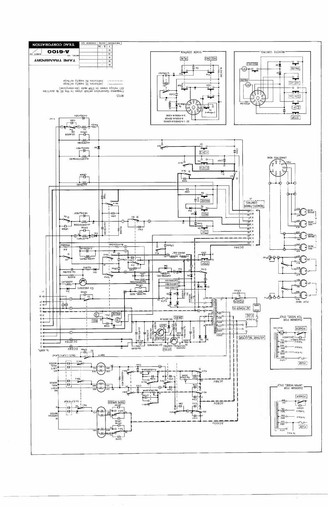
5. TAPE TRANSPORT PARTS LOCATION
Right-
Reel Motor
Brake Solenoid —
Capstan Solenoid
Flywheel -
Control —
PC.Board
Fuse Holder
Left Reel Motor
— Brake Solenoid
( -Cl 6
— Freq. Selector
SW 50Hz^60Hz
Fig. 5-1 Tape Transport Parts Location
NOTE
For ordering parts, refer to the exploded view of the PARTS LIST. An accompanying listing provides the correct part numbers.
-6-

Fig. 6-1 Rear Panel and Bottom Plate Fig. 6-2 Wood Sides
Most amplifier checks and adjustments can be made from the bottom with the plate removed.
These adjustments should be performed by experienced technicians, and then only when going through the complete test and check pro¬ cedures on the unit which is being tested.
HEAD ASSEMBLY REPLACEMENT--
To change the head assembly as a unit, remove the 4 mounting screws. Note the positions of the wires on the circuit board before unsoldering. Solder wires of the new assembly in ex¬ actly the same positions. Refer to Fig. 8-3 Head Wiring Section.
Fig. 6-3 Head Assy Removal

REMOVAL OF CAPSTAN MOTOR
1. Remove the 3 screws holding the capstan motor.
2. Unsolder the 6 wires connecting the capstan motor.
3. Remove the 4 screws holding the capstan motor. Watch for the Rubber Cushions.
4. Loosen the 2 set screws (hex head) in pulley and lift off pulley.
- NOTE - Clean the drive belt with TZ-261B and the motor pulley and capstan flywheel with TZ-261A. Be sure to note the color code of the wires so you can replace them correctly.
Fig. 6-4 Capstan Motor Removal
REMOVAL OF CAPSTAN ASSEMBLY-
1. Unscrew capstan cover (front panel).
2. Remove 2 screws from rear bracket, allow bracket to drop toward floor of case.
3. Remove capstan belt. 4. Loosen 2 screws in capstan ass'y
flywheel. Remove flywheel. 5. Remove 3 screws in capstan ass'y. 6. Gently move capstan ass'y up and
down until it slides out of panel.
Fig. 6-5 Capstan Assy Removal
- 8 -

REMOVAL OF REEL MOTOR ASSEMBLY
1. Disconnect the 4 motor wires from terminals and release wire harness straps.
2. Loosen 2 set screws (hex head) in Brake drum (A) and 2 in the Reel Turntable assembly (F). Lift off these parts.
3. Remove 4 screws securing the Brake Assembly (D) to the motor. Carefully lift off the Brake Retainer (B) with its 2 wires still connected to the Brake Solenoid (C).
4. Remove 4 screws securing Reel Motor (E) to chassis through the front panel.
NOTE Reel motor assemblies are mirror images of each other; these as¬ semblies are not interchangeable.
Fig. 6-6 Reel Motor Replacement Step 1. Fig. 6-7 Reel Motor Assy Disassembly

REMOVAL OF TENSION ARMS LEFT AND RIGHT
See illustration for complete disassembly instructions.
CAUTION Do not over-tighten screws holding right tension arm. Insulating spacer and micro-switch are easily broken by excess pressure.
IMPORTANT After reassembly check clearance to ascertain that arm moves freely and is not binding.
Fig. 6-8 Tension Arms Removal
HEAD REPLACEMENT
To replace a single head, a nut driver is required. Remove the 2 nuts on the defective head through the access hole provided, this releases the head from the mounting plate. Rewire the new heads as shown in Fig. 8-3. Replace the nuts securing the new head to the plate. Perform head alignment before operation.
Shield(A)
3D
T-308
Fig, 6-9 Head Replacement
-10-

7. LINE VOLTAGE AND FREQUENCY CONVERSION
Unit must be set to the power line frequency available. Improper frequency setting will result in a 20% error between the tape speed and reel motors torque. Remove power plug before making voltage conv.
.... NOTE If it should be necessary to convert the A-6100/A-6300 deck to operate from a power source of different voltage or frequency, it may be easily accomplished as follows:
US (TCA) model is preset to 117V AC and 60 Hz. No frequency conver¬ sion is required.
VOLTAGE CONVERSION:
The A-6100/A-6300 (EX) model may be set for 100,117,220,or 240 volts. To change the voltage, unscrew the fuse in the center of the voltage selector plug. Pull out the plug and reinsert it so the desired voltage shows in the cut-out. Reinstall the fuse.
FREQUENCY CONVERSION:
1. Disconnect the power cord and all connecting cables. 2. Take off tape deck rear cover by removing the 6 screws holding
it. The right side-panel may also be removed for your conve¬ nience.
3. To convert the unit from 50 to 60 Hz operation reposition the capstan belt as shown in the illustration below.
4. The frequency selector switch on the PC Board to the right of the capstan motor must be switched to the frequency of the power line.
5. Reinstall rear cover and side panel.
Fig. 7-2 Frequency Conversion
-11-
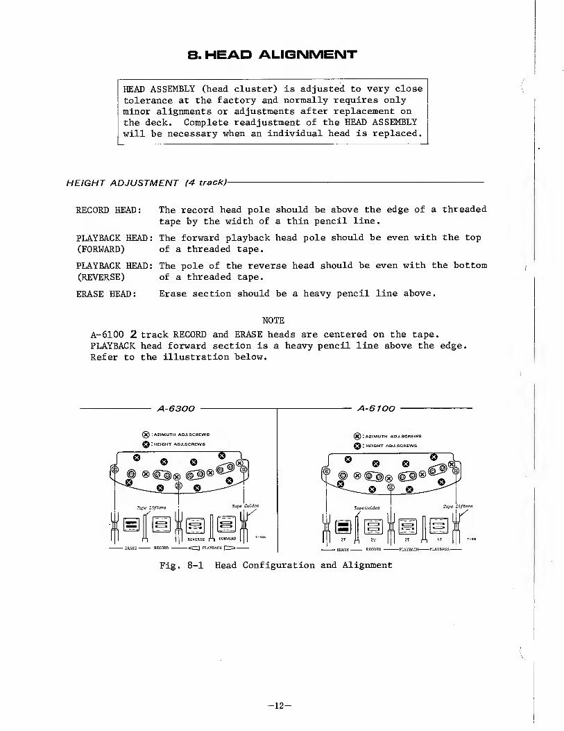
8. HEAD ALIGNMENT
HEAD ASSEMBLY (head cluster) is adjusted to very close tolerance at the factory and normally requires only minor alignments or adjustments after replacement on the deck. Complete readjustment of the HEAD ASSEMBLY will be necessary when an individual head is replaced.
HEIGHT ADJUSTMENT (4 track)-
RECORD HEAD: The record head pole should be above the edge of a threaded tape by the width of a thin pencil line.
PLAYBACK HEAD: The forward playback head pole should be even with the top (FORWARD) of a threaded tape.
PLAYBACK HEAD: The pole of the reverse head should be even with the bottom (REVERSE) of a threaded tape.
ERASE HEAD: Erase section should be a heavy pencil line above.
NOTE
A-6100 2 track RECORD and ERASE heads are centered on the tape. PLAYBACK head forward section is a heavy pencil line above the edge. Refer to the illustration below.
Fig. 8-1 Head Configuration and Alignment
-12-

MIS-ALIGNMENT OF THE HEADS -EXAMPLES-
* ALIGNMENT - The physical positioning of a tape head relative to the tape itself. Alignment in all respects must conform to rigid requirements in order for a unit to function properly.
* AZIMUTH - The angle of a tape head pole-piece gap relative to the direction of tape travel.
NOTE: In order for a tape unit to work at its best, with its own tapes as well as ones made on other units, its play and record heads must be aligned to correct the 4 possible errors as illust¬ rated below.
T-330
Fig. 8-2 Head Mis-Alignment -Examples-
HEAD WIRING
A-61QO A-6300
Fig. 8-3 Head Wiring
-13-
9. MEASUREMENT AND ADJUSTMENT -MECHAMIC AL¬
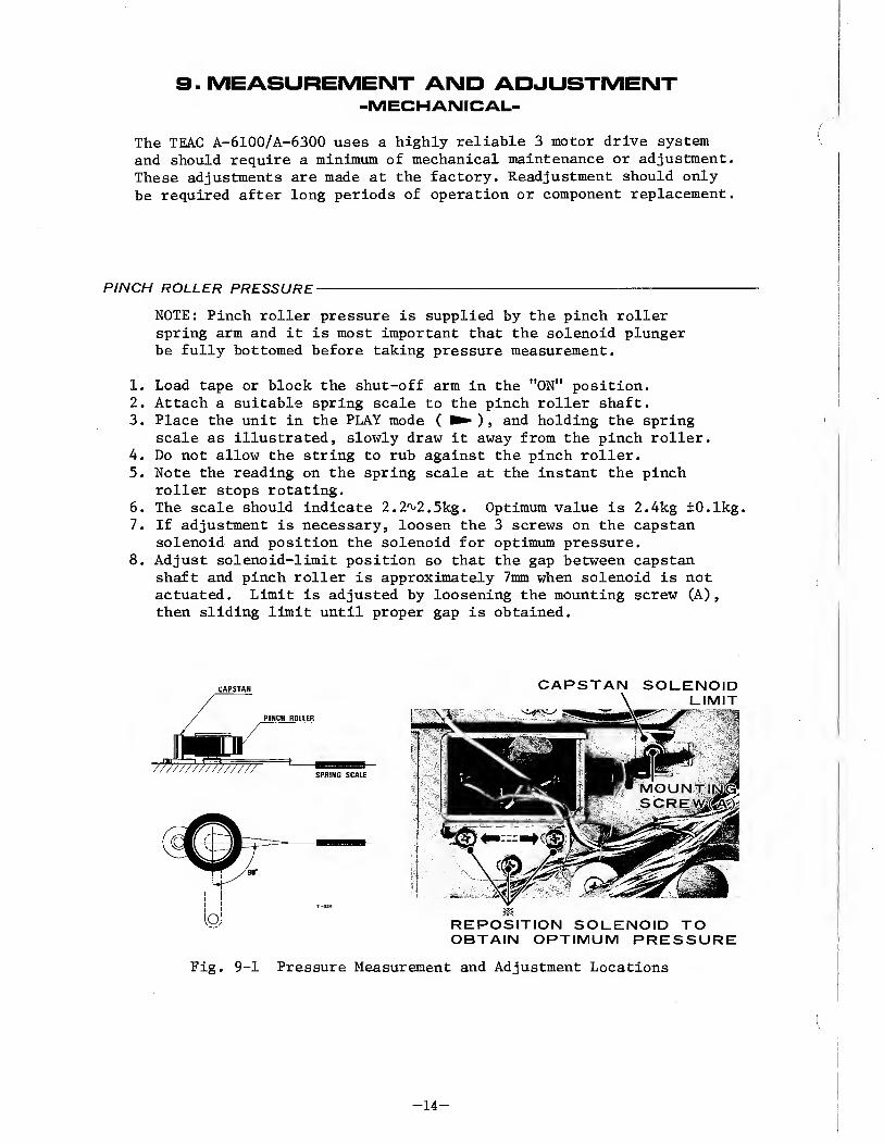
T’he TEAC A-6100/A-6300 uses a highly reliable 3 motor drive system and should require a minimum of mechanical maintenance or adjustment. These adjustments are made at the factory. Readjustment should only be required after long periods of operation or component replacement.
PINCH ROLLER PRESSURE-
NOTE: Pinch roller pressure is supplied by the pinch roller spring arm and it is most important that the solenoid plunger he fully bottomed before taking pressure measurement.
1. Load tape or block the shut-off arm in the "ON" position. 2. Attach a suitable spring scale to the pinch roller shaft. 3. Place the unit in the PLAY mode ( ► ), and holding the spring
scale as illustrated, slowly draw it away from the pinch roller. 4. Do not allow the string to rub against the pinch roller. 5. Note the reading on the spring scale at the instant the pinch
roller stops rotating. 6. The scale should indicate 2.2^2.5kg. Optimum value is 2.4kg ±0.1kg. 7. If adjustment is necessary, loosen the 3 screws on the capstan
solenoid and position the solenoid for optimum pressure. 8. Adjust solenoid-limit position so that the gap between capstan
shaft and pinch roller is approximately 7mm when solenoid is not actuated. Limit is adjusted by loosening the mounting screw (A), then sliding limit until proper gap is obtained.
IMDT7 7'ff///yfJ7jW77T
PINCH ROLLER
SPRING SCALE
CAPSTAN SOLENOID
REPOSITION SOLENOID TO OBTAIN OPTIMUM PRESSURE
Fig. 9-1 Pressure Measurement and Adjustment Locations
-14-

BRAKE TORQUE
The brake torque is actuated mechanically. Pressure is set by the variable spring force. While making these measurements and adjust¬ ments, be careful not to bend the brake bands. As brake torque will change with cleaning, brake drums and brake shoes should be cleaned only when absolutely necessary. If cleaning is required, use TEAC cleaner TZ-261B. After cleaning operate the machine for a month of normal operation before performing the procedures below.
Brake adjustments are made with _N0 power connected to the equip¬ ment .
1. Place an empty 2" hub reel on the left reel table, and fasten one end of a 30" length of string to the reel anchor.
2. Wind several turns of string counterclockwise around the hub and attach a suitable spring scale to the free end of the string.
3. Take a reading only when the reel is in steady motion since the force required to overcome static friction will produce a false, excessively high initial reading.
4. The reading should be 1000 g-cm ±200 g-cm. 5.. If adjustment is required, loosen the 2 screws shown and position
the brake for optimum torque. 6. The adjustment of the right brake is the same, with the exception
that rotations are clockwise. (Wind string CLOCKWISE around reel hub.)
NOTE: The difference in reading between the right and left brakes should be kept within 100 g-cm.
To measure torque when using a reel with a hub radius of other than 5.0cm refer to the following page.
Fi g. 9-2 Torque Measurement and Brake Assy ADJ. Location
-15-
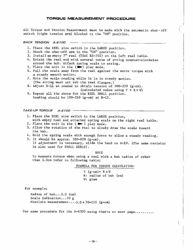
TORQUE MEASUREMENT PROCEDURE
All Torque and Tension Measurement must be made with the automatic shut- off switch (right tension arm) blocked to the "ON" position.
BACK TENSION A-6100 ---
1. Place the REEL size switch to the LARGE position. 2. Block the shut-off arm in the "ON" position. 3. Install an empty 7" reel (TEAC RE-702) on the left reel table.
4. Rotate the reel and wind several turns of string counter-clockwise around the hub. Attfach spring scale to string.
5. Place the unit in the (^) play mode. 6. Pull the scale away from the reel against the motor torque with
a steady smooth motion. 7. Note the scale reading while it is in steady motion.
(The string must not rub the reel flanges.) 8. Adjust R-ll as needed to obtain tension of 300-320 (g-cm).
(calculated value using T = R x W) 9. Repeat all the above for the REEL SMALL position.
Reading should be 180-210 (g-cm) at R-12.
TAKE-UP TORQUE A-6100 -
1. Place the REEL size switch to the LARGE position, with empty reel and attached spring scale on the right reel table.
2. Place the unit in the ( ) play mode.
3. Allow the rotation of the reel to slowly draw the scale toward the hub.
4. Hold the spring scale with enough force to allow a steady reading. 5. It should be approx. 780-820 (g-cm).
If adjustment is necessary, slide the band on R-10. (The same resistor is also used for SMALL REELS).
NOTE To measure torque when using a reel with a hub radius of other than 3.0cm refer to following table;
FORMULA FOR TORQUE CALCULATION:
T (g-cm)= R x W R: radius of hub (cm) W: gram
For example;
Radius of hub...3.0 (cm) Scale indication...70 g
Absolute measurement....3.0x70=210 (g-cm)
Use same procedure for the A-6300 using charts on next page
-16-
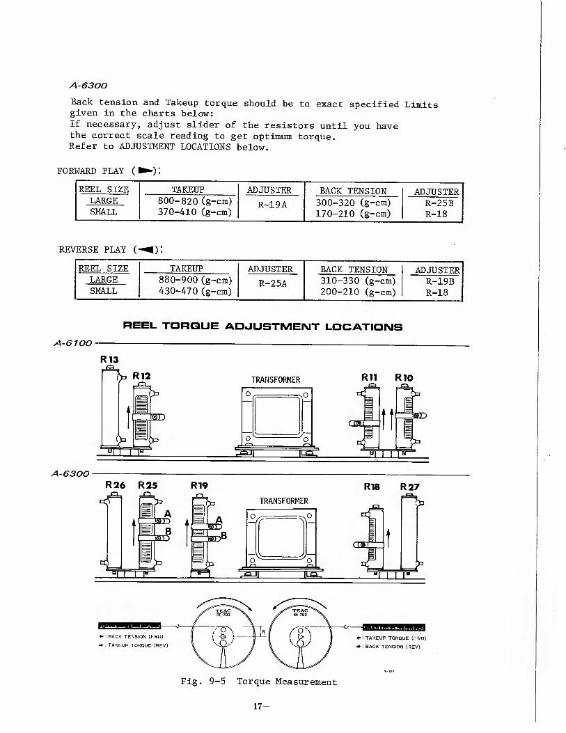
A-6300
Back tension and Takeup torque should be to exact specified Limits given in the charts below:
If necessary, adjust slider of the resistors until you have the correct scale reading to get optimum torque. Refer to ADJUSTMENT LOCATIONS below.
FORWARD PLAY (i
REEL SIZE TAKEUP ADJUSTER BACK TENSION ADJUSTER LARGE SMALL
800-820 (g-cm) 370-410 (g-cm)
R-19A 300-320 (g-cm) 170-210 (g-cm)
R-25B R-18
REVERSE PLAY (
REEL SIZE LARGE SMALL
TAKEUP 880-900 (g-cm) 430-470 (g-cm)
ADJUSTER
R-25A
BACK TENSION 310-330 (g-cm) 200-210 (g-cm)
ADJUSTER R-19B R-18
>11
I ... 1.. mIi
[»)

REEL HEIGHT ADJUSTMENT
Reel height Adjustment is required only if a motor has been re¬ placed or if tape rubs excessively against the reel flanges. Adjustment is accomplished by loosening the reel set screws and moving the reel table on the motor shaft as shown in the illustration below. Remove the wooden panel on the right side of the deck for access to the Set Screws in the reel motor shaft. Reel table should be adjusted using standard 7" reels. With a tape loaded on the machine, position the reel table height for smooth tape travel. Be sure to tighten the Set Screws after adjustment is made.
T-178
Fig. 9-6 Reel Height Adjustment
FLUTTER-
Flutter should be measured in playback mode using a TEAC flutter free tape YTT-2004 (15ips), YTT-2003 (7-l/2ips), YTT-2002 (3-3/4ips) and MEGURO model MK-665B flutter meter. Measurement of flutter should be made in accordance with NAB standards. Values obtained with different standards or equipment cannot be compared. Flutter should not exceed: 15ips: 0.15% (RMS)
7-l/2ips: 0.18% (RMS) 3-3/4ips: 0.20% (RMS)
These figures apply to any tape position and direction (such as full take-up reel, full supply reel or about mid point). If there is excessive wow and flutter, examine the pinch roller, belt, motors, capstan shaft, and reel rest for "grease", "oil", "dirt" and/or "wear". Also examine the tape counter ass'y for evenness of operation.
TAPE SPEED-
The tape speed should be measured using TEAC flutter free tape, Model YTT-2004 (15 ips), YTT-2003 (7-1/2 ips), YTT 2002 (3-3/4 ips). These tapes contain a highly accurate 3 kHz tone. Connect a digital frequency counter to either line OUTPUT jack. The indicated frequency should be 3 kHz (± 30 Hz or less) for both speeds.
Fig. 9-7 Test Equipment Set-up
-18-

A-61□□
1 O. ELECTRICAL ADJUSTMENT GENERAL NOTICE
* Before performing maintenance on this unit, thoroughly clean and demagnetize the entire tape path. TEAC maintenance equipment to be used:
TEAC TZ-261 A/B for cleaning TEAC E-3 for demagnetizing
* The unit must be matched to the voltage and frequency of your
locality.
* TEAC specified standard Test Tapes and test equipment must be used when performing maintenance to insure reliable results.
* Procedures for checks and adjustments, unless otherwise indicated, are for the left channel at a tape speed of 7-1/2 ips (19 cm). The
same procedures are to be applied to the right channel and again for
both channels at 15ips (38 cm).
* Power supply check and adjustment: Check the voltage at VR-1 and adjust to +24V DC if required. (Refer to Control Board drawing on the TAPE TRANSPORT CIRCUIT DIAGRAM.)
* All amplifier checks and adjustments can be made from the bottom of the deck with the cover removed.
ADJUSTMENT LOCATIONS
VR308 Peak Lamp Level Adj. Only A-6100
Fig. 10-1 Adjustment Locations
-Electrical-
-19-

A-6100 ONLY see page 30 for A-6300
11. MEASUREMENT AND ADJUSTMENT -ELECTRICAL-
ADJUSTMENT SEQUENCE-
PREPARATIONS ---
The following checks and adjustments must be performed with the switches of the A-6100 set as outlined below.
OUTPUT LEVEL SW^-LOW METER SW — NORMAL (on the Rear Panel) SPEED SW —» LOW PLAYBACK HEAD SW —- 2 track
PLAYBACK HEAD AZIMUTH ADJUSTMENT-
NOTE: After head replacement or if, during playback, a slight pressure on the tape against the heads results in a higher indication at the Test-Set (M-826A), head azimuth should be readjusted.
Coarse Adjustment:
1. Connect a Test-Set to either OUTPUT jack; open the head housing. 2. Thread a TEAC Test Tape YTT-1003 on the unit.
Play the 15 KHz Test Tone in Section 2 of the Test Tape. 3. Slowly rotate the azimuth screw until maximum indication
is obtained on the Test-Set. 4. Repeat the procedure for the 4 track play head.
Fine Adjustment:
NOTE: It is absolutely essential to accomplish the coarse adjustment before performing the fine adjustment to avoid phase errors larger than 45? After coarse adjustment, do not make large corrections, turn azimuth screw 1/4 turn or less.
5. Connect the test equipment as shown in Fig.11-1. 6. Play a 50 Hz^lO kHz signal and adjust the azimuth screw
until the oscilloscope shows that the signals are less than 45° out of phase ( 2 track and 4 track ).
7. Secure the screw with a drop of Locking Paint.
-20-

Fig. 11-1 Fine Adjustment Set-up -Head Alignment-
SPECIFIED OUTPUT LEVEL SETTING-
NOTE: Connect a lOkft load to the OUTPUT jacks for all audio measurements when not using TEAC Test Set (M-826A).
1. Place the MONITOR switch to the TAPE position. 2. Place the PLAYBACK HEAD switch to the 2 track position. 3. Turn the OUTPUT control fully clockwise (MAX). 4. Thread TEAC Test Tape YTT-1003 on the unit. Operate at LOW speed. 5. Play the 400 Hz signal in section 1 of the Test Tape. 6. Check for -5.5 dB at the OUTPUT jacks.
7. Align the Reference marks on the controls so that they are at the 0 VU (3 o’clock) position. This will give approx. -8 dB at the OUTPUT jacks.
8. Readjust VR-201/203 for a -8 dB level at the OUTPUT jacks.
IMPORTANT: This is the specified output level setting. Do not disturb this setting until the remaining adjustments have been completed.
OUTPUT
-21-

VU METER CALIBRATION
1. Place METER switch in NORMAL position. Playback head switch to 2 track. 2. Play the 400 Hz tone (1% THD) in Section 1 of the Test Tape. 3. With MONITOR switch at TAPE position, adjust VR-202/204 for
a reading of 0 VU on the lower scale of the VU meter.
FREQUENCY RESPONSE 2T.4T-
The following check should be run on both PLAYBACK heads (2T and 4T)
1. Place Tape SPEED switch in LOW position. 2. Thread a TEAC Test Tape YTT-1003 on the unit. 3. Compare the readings obtained on the Test Set with the response
limits given in Fig. 11-2. 4. If adjustment is required, adjust VR-101/103 for Equalization at
7-1/2 ips (19 cm) speed. 5. Place Tape SPEED switch in HIGH position. 6. Thread a TEAC Test Tape YTT-1004 on the unit. 7. Repeat step 3. Check for best frequency response. 8. If adjustment is required, adjust VR-102/104 for Equalization at
15ips (38 cm) speed . NOTE
If the frequency response does not meet specified response limits especially at the high end, the specified head should be carefully recleaned. If frequency response is still out of specifications, head azimuth must be re-adjusted.
NOTE
If the frequency response does not meet
specified response limits, especially at the high end, the specified head should be carefully recleaned. If fre¬ quency response is still out of speci¬ fications, head azimuth must be re¬ adjusted.
Fig. 11-2 Frequency Response Limits -Playback-
DIFFERENCE LEVEL (Between Channels) -
With a Test-Set connected to the OUTPUT jacks and using TEAC Test Tape, the readings listed below should be obtained at the specified frequency and tape speeds.
0.5 dB or less at 400 Hz signal 3 dB or less at 40 Hz-22 KHz (HIGH speed)
40 Hz-14 KHz (LOW speed)
4 dB or less at 400 Hz- 16 KHz for 4 track
-22-
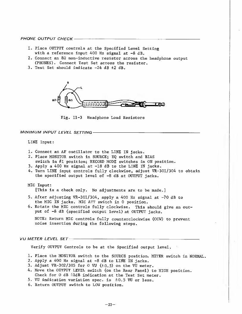
PHONE OUTPUT CHECK
1. Place OUTPUT controls at the Specified Level Setting with a reference input 400 Hz signal at -8 dB.
2. Connect an 8ft non-inductive resistor across the headphone output (PHONES). Connect Test Set across the resistor.
3. Test Set should indicate -24 dB ±2 dB.
R
Fig. 11-3 Headphone Load Resistors
MINIMUM INPUT LEVEL SETTING--
LINE Input:
1. Connect an AF oscillator to the LINE IN jacks.
2. Place MONITOR switch in SOURCE; EQ switch and BIAS switch in #1 position; RECORD MODE switches in ON position.
3. Apply a 400 Hz signal at -18 dB to the LINE IN jacks. 4. Turn LINE input controls fully clockwise, adjust VR-301/304 to obtain
the specified output level of -8 dB at OUTPUT jacks.
MIC Input:
[This is a check only. No adjustments are to be made.]
5. After adjusting VR-301/304, apply a 400 Hz signal at -70 dB to the MIC IN jacks. MIC ATT switch in 0 position.
6. Rotate the MIC controls fully clockwise. This should give an out¬ put of -8 dB (specified output level) at OUTPUT jacks.
NOTE: Return MIC controls fully counterclockwise (CCW) to prevent noise insertion during the following steps.
VU METER LEVEL SET--
Verify OUTPUT Controls to be at the Specified output level.
1. Place the MONITOR switch to the SOURCE position. METER switch in NORMAL. 2. Apply a 400 Hz signal at -8 dB to LINE IN jacks. 3. Adjust VR-302/305 for 0 VU (±0.5) on the VU meter. 4. Move the OUTPUT LEVEL switch (on the Rear Panel) to HIGH position.
Check for 0 dB ±ldB indication at the Test Set meter. 5. VU indication variation spec, is ±0.5 VU or less. 6. Return OUTPUT switch to LOW position.
-23-

BIAS TRAP ADJUSTMENT
The following check and adjustments must be performed with the EQ switch in the #1 position.
1. Place BIAS switch in #1 position, MONITOR switch in TAPE position, and RECORD MODE switch to "ON". Depress REC and PAUSE buttons.
2. Connect a VTVM or oscilloscope to the junction of C-320/L-302 (Left channel), C-344/L-304 (Right channel).
3. Adjust L-302, L-304 for minimum reading.
Fig.11-4 Bias Trap Check Point and Adjustment Locations
BIAS ADJUSTMENT-
NOTE: Adjust bias traps (above) before proceeding. The following adjustments are made only at 7-1/2 ips ( 19 cm ) tape speed. The bias oscillator frequency is 100 kHz (±5 kHz).
RECORD BIAS switch #1 position
1. Thread record Test Tape YTT-8013 on the unit. 2. Place the REC BIAS switch to #1 and place the unit
in the record mode. 3. Place the MONITOR switch in the TAPE position. 4. Apply a 7 KHz signal at -18dB to the LINE IN jack. 5. While recording, adjust capacitor VC-401/402 for peak
recording on the Test Set. From the peak, turn the capacitors clockwise until a decrease of 2.5 dB is obtained.(N.B.: This will be slight overbias setting as is usually preferred.)
Fig. 11-5 Bias Limits Chart
-24-

RECORD HEAD AZIMUTH ADJUSTMENT-—-
Coarse Adjustment:
NOTE: The effect of turning the azimuth screw will not immedi¬ ately register on the Test Set. A slight delay will be noticed. Therefore, the screw must be rotated slightly with a pause to see the effect.
1. Connect a Test Set to the OUTPUT jack and an AF oscillator to the LINE IN jack, then set the AF oscillator to 10 kHz.
2. Make certain that the LINE controls are at the Specified Input Level positions.
3. Place the MONITOR switch to SOURCE and adjust the AF oscillator to obtain a signal of 20 dB below the Specified Output Level. (The Test Set will indicate -28 dB.)
4. Thread a record Test Tape on the unit. 5. Place the MONITOR switch in the TAPE position. 6. While recording adjust the azimuth screw for maximum indication
on the Test Set.
Fine Adjustment:
NOTE: It is absolutely essential to accomplish the coarse ad¬ justment before performing the fine adjustment to avoid phase error larger than 45°
7. Connect the test equipment as shown in Fig.11-1. 8. Apply a 10 kHz signal at -28 dB to the LINE IN jacks and record
this signal.
9. Carefully adjust the azimuth screw until the oscilloscope shows the signal to be in phase.
10. Secure the screw with a drop of Locking paint.
T-293
Fig. 11-6 Phase shift
Refer to Fig. 11-1 Fine Adjustment Set-up (playback)
-25-

RECORD LEVEL SET
NOTE: The OUTPUT control must be at the specified output level position {-8 dB at OUTPUT jacks), and the LINE INPUT controls at the Specified Input Level Setting.
1. Apply a 400 Hz signal at -8 dB to the LINE IN jacks. 2. Thread a record Test Tape TEAC YTT-8013 on the unit, then set
BIAS switch to #1 position, Tape SPEED at HIGH. 3. Place the MONITOR switch in the TAPE position, LINE and OUTPUT
Controls to Specified Level position. 4. Adjust VR-303/306 for a -8 dB signal at OUTPUT jacks.
OVERALL FREQUENCY RESPONSE-
RECORD BIAS switch to the #1 position
1. Thread a blank TEAC YTT-8013 tape on the unit.
Place BIAS switch at #1 position (EQ SW at 1),tape SPEED at HIGH. 2. Apply a signal stepped from 30 Hz to 26 kHz at -28 dB to LINE IN
jacks and record it on the Test Tape. 3. Adjust L-301/303 for best response. 4. Repeat overall response check at LOW.
1 1 1 1 1 1 II '-
OVERALL (YTT'8013) : |_ 15>ps
N B M _ " " Tj
-4 _ _ T ■ ■ ■ 1 HNKlB ■ _ ■ ■
■ 1 1 1 13 1 1 H E? ■ ■ ■ ■ ■1 E ■ ■ ■ ■ ■ ■ ■ ■1 'A ■ ■ 1
J L _ L I ■ 1 ■ 1 u iH ■1 ■ ■ mi IHBH ■
1 ■ 1 1 1 ■ 1 1 ■ 1 i-1—i—l i M M_l_i_i...I_i_i i i mil_i_i_i_
20 50 100 200 500 IK 2K 5K 10K 15K 20K 30K 50K
Fig. 11-7 Frequency Response Limits -RECORD-
RECORD BIAS switch to the #2 position
5. Thread a blank TEAC YTT-8003 tape on the unit, place BIAS switch
at #2 position (EQ SW at 1),tape SPEED switch at LOW. 6. Apply a signal stepped from 40 Hz to 22 kHz at -28 dB to LINE IN
j acks.
7. If further adjustment is required, adjust VR-401 for best response.
8. Repeat overall response check at both speeds.
-26-

1 1 1 1 1 1 1 1 1 1
OVERALL (YTT -8003) 1 1 1 1
_l L L 15ips i 1 i ■
+4 wm ■ — Tip ■ ■ ■ ■ ■ 1
_
■ - - ■ ■
-4 ■ ■ ■ 1 ■ 1 ■ ■ i 1 II
■ ■ 1 — m
■ 1 i IK i 1 i 1 ■ E7 _ _ _ HI m m 5 ■ ■ ■ si
■ ■ ■ ■1 !■■■ IS ■ ■ ■ _ r ■ HI
1 ■ 5 3 ■ 1 \^m ■ ■ 1 1 !■ LI ■ i 1 i 1 i ■ i I 1 1 1 1 i
20 50 100 200 500 IK 2K 5K 1 OK 15K 20K 30K 50K
Fig. 11-8 Frequency Response Limits -RECORD-
OPT1MUM ERASURE MEASUREMENT-
NOTE: To measure erase efficiency, a 1 kHz Band Pass Filter (TEAC M-206A filter) must be used.
T-295
Fig. 11-9 Erasure efficiency check Set-up
Following is the measurement procedure at 15 ips using the TEAC reference tape, Type YTT-8013:
1. Apply a 1 KHz signal at lOdB above the operating level of -8dB, to the left channel LINE IN jack.
2. Make a 30 second recording of the above signal and rewind to beginning of this recording. Measure OUTPUT level during recording.
3. Disconnect the 1 KHz signal source (A.F. oscillator) from the LINE IN jack.
4. Connect a TEAC Test Set (M-826A), or equivalent, to the left channel OUTPUT jack, through a 1 KHz Narrow Band Pass Filter (TEAC M-206).
5. Set the recorder output switch to "TAPE monitor". 6. Put recorder in the RECORD mode and "record" (erase) over this previous
recording; then rewind to begining again. 7. Put recorder in play mode and monitor the left channel output on the
Test Set meter. 8. Difference in output level, against the OUTPUT level in Step 2,
should be more than -65 dB (2 track). 9. Repeat the same procedure on the right channel.
~27-

LEVEL VARIATION
1. Thread a reel of high output tape YTT-8013, and select HIGH (15ips) SPEED position.
2. Record a variety of frequencies, such as 400 Hz, 2 kHz, 5 kHz, 8 kHz, 10 kHz, etc., at the specified input setting with the RECORD BIAS switch #1 position. Record approximately 10 seconds of each frequency.
3. During playback the output level should not vary more than 0.5dB at 400 Hz, 1 dB at 5 KHz to 20 KHz.
4. With the unit at tape SPEED LOW ( 7—1/2 ips ), the tolerances are the same as at HIGH (15ips). Repeat step 2,3 with tape SPEED selector in LOW position.
CHA NNEL - TO- CHA NNEL CROSS TALK REJECTION
Following is the measurement procedure 15 ips using the TEAC reference tape. Type YTT-8013:
1. Apply a 1 KHz signal at the operating level of -8dB, to the left channel LINE IN jack.
2. Install a short-circuiting plug to the right channel LINE IN jack. 3. Make a 30 second recording on both channels, then rewind to beginning
of this recording.
4. Connect a TEAC Test Set (M-826A), or equivalent, to the right channel OUTPUT jack through a 1 KHz narrow Band Pass Filter (TEAC M-206).
5. Put recorder in PLAY mode and monitor the "no signal" right channel on the Test Set meter. The reading should be -45 dB min.
PEAK LEVEL INDICATOR ADJUSTMENT ---—-
1. Set METER switch to NORMAL, SPEED switch to HIGH. Adjust VR-307/308 so that the peak level indicator ignites by a 400 Hz/0.775V (OdB)
signal (8dB higher than normal input level) and extinguishes at a 0.5dB lower signal.
NOTE: Adjust one channel at a time while applying no signal to the other channel.
2. After above adjustment, set SPEED switch to LOW and check that it will ignites at an input level of 615mV (-2 dB).
3. Set METER switch to HIGH and check to see that the peak level indicator ignites at an input level of 1.09V (+3dB) with tape speed at HIGH, and also at an input level of 869mV (+ldB) with tape speed at LOW.
-28-

SIGIMAL-TO-NOISE RATIO
PLAYBACK
IMPORTANT OUTPUT controls should be at the Specified Output Level Settings. The signal-to-noise ratio must meet factory standards. The values given are obtained using an unweighted Test Set (M-826A), with the supply and take-up motors having voltage applied but not rotat¬ ing.
1. Thread a blank YTT-8013 tape on the unit leaving the tape outside the cap¬ stan and pinch roller.
2. Hold the supply reel stationary and depress the play (►) button.
3. The Test Set connected to the OUTPUT jacks should indicate -58 dB or less.
4. This corresponds to a signal-to-noise ratio of 50 dB (difference between residual noise -58 dB and specified output level -8 dB for 1% THD).
NOTE Tape SPEED at LOW (7-1/2 ips) and play¬ back head switch at 2 track position.
Fig. 11-10 Signal/Noise Computation
OVERALL-
IMPORTANT: Clean and demagnetize the heads before proceeding. It is extremely important that all tests described in the pre¬ ceding paragraphs have been completed and that all controls are left at their specified settings.
1. Thread a blank Test Tape YTT-8013 on the unit.
2. Remove the AF oscillator from the LINE IN jacks. 3. Place the unit in the RECORD mode with "no signal" applied.
Note the point on the index counter where recording begins. 4. Rewind the tape to the beginning point and play it back. 5. The noise level as indicated on the Test Set should be -56 dB
or less. NOTE: Tape SPEED at LOW.
NOTE: Bias, erase and playback amplifier noise are all included in this measurement. All frequencies between 20 Hz and 26 kHz are measured unweighted.
-29-

4 TRACK STEREO TAPE DECK
For mechanical checks and adjustments, refer to the A-6100 section. Electrical adjustments are substantially different, so the following section applies only to the A-6300.

A-6300
1 2. ELECTRICAL ADJUSTMENT GENERAL NOTICE
* Before performing maintenance on this unit, thoroughly clean and demagnetize the entire tape path. TEAC maintenance equipment to be used:
TEAC TZ-261 A/B for cleaning TEAC E-3 for demagnetizing
* The unit must be matched to the voltage and frequency of your locality.
* TEAC specified standard Test Tapes and test equipment must be used when performing maintenance to insure reliable results.
* Procedures for checks and adjustments, unless otherwise indicated, are for the left channel at a tape speed of 7-1/2 ips (19 cm). The
same procedures are to be applied to the right channel and again for
both channels at 3-3/4 ips (9.5 cm).
* Power supply check and adjustment:
Check the voltage at VR-1 and adjust to +24V DC if required. (Refer to Control Board drawing on the TAPE TRANSPORT CIRCUIT DIAGRAM.)
* All amplifier checks and adjustments can be made from the bottom of the deck with the cover removed.
ADJUSTMENT LOCATIONS
Fig. 12-1 Adjustment Locations -Electrical-
-31-

13. MEASUREMENT AND ADJUSTMENT -ELECTRIC AL-
ADJUSTMENT SEQUENCE
POWER SUPPLY CHECK AND ADJUSTMENT-
1. Place the power switch to the ON position. 2. Connect a VTVM across C-5. 3. Check the voltage at VR-1 and adjust for +24V DC.
PLAYBACK HEAD AZIMUTH ADJUSTMENT-
NOTE: After head replacement or if, during playback, a slight pressure on the tape against the heads results in a higher indication at the Test-Set (M-826A), head azimuth should be readjusted.
Coarse Adjustment:
1. Connect a Test-Set to either OUTPUT jack; remove the head Housing. 2. Thread a TEAC Test Tape YTT-1003 on the unit.
Play the 15 KHz Test Tone in Section 2 of the Test Tape. 3. Slowly rotate the azimuth screw until maximum indication
is obtained on the Test-Set.
4. Repeat the procedure in Reverse play mode for the Reverse play head.
Fine Adjustment:
NOTE: It is absolutely essential to accomplish the coarse adjustment before performing the fine adjustment to avoid phase errors larger than 45° After coarse adjustment, do not make large corrections, turn azimuth screw 1/4 turn or less.
5. Connect the test equipment as shown in Fig.11-1. 6. Play a 50 Hzn/10 kHz signal and adjust the azimuth screw
until the oscilloscope shows that the signals are less than 45° out of phase (Forward and Reverse modes).
7. Secure the screw with a drop of Locking Paint.
-32-

Fig.13-1 Fine Adjustment Set-up -Head Alignment-
SPECIFIED OUTPUT LEVEL SETTING-
NOTE: Connect a lOkfi load to the OUTPUT jacks for all audio measurements when not using TEAC Test Set (M-826A).
1. Place the MONITOR switch to the TAPE position. 2. Turn the OUTPUT control fully clockwise (MAX). 3. Thread TEAC Test Tape YTT-1003 on the unit. Operate at HIGH speed. 4. Play the 400 Hz signal in section 1 of the Test Tape. This tone is
recorded at the operating reference level (1% THD level). 5. Adjust VR-201/203 to obtain an output of -2 dB at the OUTPUT jacks. 6. Align the reference marks on the controls so that they are at the 2
o'clock position. This will give approximately -8 dB at the OUTPUT jacks.
7. Readjust VR-201/203 for a -8 dB level at OUTPUT jacks.
IMPORTANT: This is the specified output level setting. Do not disturb this setting until the remaining adjustments
have been completed. Mark with "Memory Marker".
-33-

VU METER CALIBRATION
1. Place METER switch in NORMAL position. 2. Play the 400 Hz tone (1% THD) in Section 1 of the Test Tape. 3. With MONITOR switch at TAPE position, adjust VR-202/204 for
a reading of 0 VU on the lower scale of the VU meter.
FREQUENCY RESPONSE-
1. Place Tape SPEED switch in LOW position. 2. Thread a TEAC Test Tape YTT-1002 on the unit. 3. Compare the readings obtained on the Test Set with the response
limits given in Fig. 11-2. 4. If adjustment is required, adjust VR-101/103 for Equalization at
3-3/4 ips (9.5 cm) speed. 5. Place Tape SPEED switch in HIGH position. 6. Thread a TEAC Test Tape YTT-1003 on the unit. 7. Repeat step 3. Check for best frequency response. 8. If adjustment is required, adjust VR-102/104 for Equalization at
7-1/2 ips (19 cm) speed. 9. Repeat all the above for the Reverse play mode.
Performance should be identical or within specifications.
NOTE
If the frequency response does not meet specified response limits especially at the high end, the specified head should be carefully recleaned. If frequency response is still out of specifications, head azimuth must be re-adjusted.
in ■111 ■ ■ ■ i 1 ■ 1 1 1
■ 1 ■ n ■1 ■HI | 1 1 i 1 s ■ ■ ■
■ ■ ■ ■ ■ II ■tel* S ■ ■ i i] ■
■ ■ 1 ■ ■ rs
E ■ ■ m m ■ ■ ■1 ■ 1 i — - ■ ■ 1 _ jn
in i ■
1 ■ II ■1 m ■ 1 ! ! 1 ■ J ■
E - ■ 1 II ■ ■ MBS ■ ■ i i ■ Hi - - ■ ■ ■ 1 m\ a ■ _ ■ ■1 ■ ■ ■ ■ m ■ ■ a Ej ■ ■ ■ ■ II HflH u ■ ■ ■ i i ■ 1
■ i n 1 ■ 1 i 1 1 ■ ■ 20 m ■ ■ n 0
1 KTi Til ■ g
1 mr 1 1
Fig. 13-2 Frequency Response Limits -PLAYBACK-
DIFFERENCE LEVEL (Between Channels) ___
10. With a Test-Set connected to the OUTPUT jacks and using TEAC Test Tape, the readings listed below should be obtained at the specified frequency and tape speeds.
0.5 dB or less at 400 Hz signal 3 dB or less at 40 Hz-22 KHz (HIGH speed)
40 Hz-14 KHz (LOW speed) and with in 4 dB for reverse play
-34-

PHONE OUTPUT CHECK
1. Place OUTPUT controls at the Specified Level Setting with a reference input 400 Hz signal at -8 dB.
2. Connect an 8ft non-inductive resistor across the headphone output (PHONES). Connect Test Set across the resistor.
3. Test Set should indicate -24 dB ±2 dB.
R
Fig. 13-3 Headphone Load Resistors
MINIMUM INPUT LEVEL SETTING-
LINE Input:
1. Connect an AF oscillator to the LINE IN jacks.
2. Place MONITOR switch in SOURCE; EQ switch and BIAS switch in #1 position; RECORD MODE switches in ON position.
3. Apply a 400 Hz signal at -18 dB to the LINE IN jacks. 4. Turn LINE input controls fully clockwise, adjust VR-301/304 to obtain
the specified output level of -8 dB at OUTPUT jacks.
MIC Input: [This is a check only. No adjustments are to be made.]
5. After adjusting VR-301/304, apply a 400 Hz signal at -70 dB to the MIC IN jacks.
6. Rotate the MIC controls fully clockwise. This should give an out¬ put of -8 dB (specified output level) at OUTPUT jacks.
NOTE: Return MIC controls fully counterclockwise (CCW) to prevent noise insertion during the following steps.
VU METER LEVEL SET-
Verify OUTPUT Controls to be at the Specified output level.
1. Place the MONITOR switch to the SOURCE position. METER switch in NORMAL. 2. Apply a 400 Hz signal at -8 dB to LINE IN jacks. 3. Adjust VR-302/305 for 0 VU (±0.5) on the VU meter.
-35-

BIAS TRAP ADJUSTMENT-
The following check and adjustments must be performed with the EQ switch in the #1 position.
1. Place BIAS switch in #1 position, MONITOR switch in TAPE position, and RECORD MODE switch to "ON". Depress REC and PAUSE buttons.
2. Connect a VTVM or oscilloscope to the junction of C-314/L-302 (Left channel), C-329/L-304 (Right channel).
3. Adjust L-302, L-304 for minimum reading.
Fig. 13-4 Bias trap check point and adjustment locations
BIAS ADJUSTMENT--
NOTE: Adjust bias traps (above) before proceeding. The following adjustments are made only at 3-3/4ips (9.5cm) tape speed. The bias oscillator frequency is 100 kHz (±5 kHz).
RECORD BIAS switch #1 position
1. Thread record Test Tape YTT-8013 on the unit. 2. Place the REC BIAS switch to #1 and place the unit
in the record mode. 3. Place the MONITOR switch in the TAPE position. 4. Apply a 7 KHz signal at -18dB to the LINE IN jack. 5. While recording, adjust capacitor VC-401/402 for peak
recording on the Test Set. From the peak, turn the capacitors clockwise until a decrease of 3 dB +0.5 dB is obtained ( N.B. This will be slight overbias setting as is usually preferred).
BIAS
Fig. 13-5 Bias limits chart
-36-

RECORD HEAD AZIMUTH ADJUSTMENT
Coarse Adjustment:
NOTE: The effect of turning the azimuth screw will not immedi¬ ately register on the Test Set. A slight delay will be noticed. Therefore, the screw must be rotated slightly with a pause to
see the effect.
1. Connect a Test Set to the OUTPUT jack and an AF oscillator to the LINE IN jack, then set the AF oscillator to 10 kHz.
2. Make certain that the LINE controls are at the Specified Input
Level positions. 3. Place the MONITOR switch to SOURCE and adjust the AF oscillator
to obtain a signal of 20 dB below the Specified Output Level.
(The Test Set will indicate -28 dB.) 4. Thread a record Test Tape on the unit. 5. Place the MONITOR switch in the TAPE position. 6. While recording adjust the azimuth screw for maximum indication
on the Test Set.
Fine Adjustment:
NOTE: It is absolutely essential to accomplish the coarse ad¬ justment before performing the fine adjustment to avoid phase error larger than 45?
7. Connect the test equipment as shown in Fig. 13-1. 8. Apply a 10 kHz signal at -28 dB to the LINE IN jacks and record
this signal. 9. Carefully adjust the azimuth screw until the oscilloscope shows
the signal to be in phase. 10. Secure the screw with a drop of Locking paint.
45° 180°
Fig. 13-6 Phase shift
Refer to Fig. 13-1 Fine Adjustment Set-up (playback)
-37-

RECORD LEVEL SET-----—_-_
NOTE: The OUTPUT control must be at the specified output level position (-8 dB at OUTPUT jacks), and the LINE INPUT controls at the Specified Input Level Setting.
1. Apply a 400 Hz signal at -8 dB to the LINE IN jacks. 2. Thread a record Test Tape TEAC YTT-8013 on the unit, then set
BIAS switch to #1 position. Tape SPEED at HIGH. 3. Place the MONITOR switch in the TAPE position, LINE and OUTPUT
Controls to Specified Level position. 4. Adjust VR-303/306 for a -8 dB signal at OUTPUT jacks.
OVERALL FREQUENCY RESPONSE-----—^-
RECORD BIAS switch to the #1 position
1. Thread a blank TEAC YTT-8013 tape on the unit.
Place BIAS switch at #1 position (EQ SW at l),tape SPEED at HIGH.
2. Apply a signal stepped from 40 Hz to 24 KHz at -28 dB to LINE IN jacks and record it on the Test Tape.
3. Adjust L-301/303 for best response. 4. Repeat overall response check at LOW speed.
1-'—1 Mill-1-1-
_ OVERALL (YTT-8013) r L 7j.ips
5 - _ : L. p v "" ' " 1
E r _ _ 1 m ■ ■ ■ ■i ■ ■ r ■ ■ ■ ■1 III IH B
1 II in- I 1 1 II ■ E _ ■ ■ ■1 !■■■ m 9 ■ ■ ■ ■1 !■■■ ■1 III IB ,+3
— ■ ■ i i n : ■J rA ■ ■ ■ ■1 ■1 ■■I ■ ■ mi
■ ■ ■ ■i !■■■■ ■ ■ ■ Bl imi “i ■1 IHI ■ -1 I ■ ■ ■i m m ■ II
125 I4KI 5K
20 —
5 0 _i _
t __ _ _ _ J
Fig.13-7 Frequency Response Limits - RECORD -
RECORD BIAS switch to the #2 position
5. Thread a blank TEAC YTT-8003 tape on the unit, place BIAS switch
at #2 position (EQ SW at l),tape SPEED switch at LOW. 6. Apply a signal stepped from 40 Hz to 22 KHz at -28 dB to LINE' IN
j acks.
7. If further adjustment is required, adjust VR-401 for best response.
8. Repeat overall response check at both speeds.
-38-

■ 1 1 1 ■ ■ ■ ■ 1
■II Iff a ! I II |
1 ■1 ii ■ ■ 1 15 ■S ■■
ii ■
n B ■ ■i ■■ £ ■ ■ ■BBBB I^^B ■i IB Hi
E ■l ii ■ ■ 1 H ■ ■ 1 H [ !] HI 1 | ■ I 1 1 ■ ■ ■
5 ■1 H ■ 111 ■ ■ Ml a ■ ■1 II m ■1 rA ■ 1 H H HI ■ 1 51 ■ pi || ^A ■I ■ ■■■ ■ ■ Ml
i Ml II ih u ■ ■ 1 ■ ■ Hi ■ 1 mi ■ 1 II 1 1 1i 1 1 ■ ■ ■
II ■ 1 1 | 1 ■ ■ 20 50 100 200 500 IK 2K 5K 10K 15K 20K 30K 50K
IN Hz
Fig. 13-8 Frequency Response limits
- RECORD -
OPTIMUM ERASURE MEASUREMENT-
NOTE: To measure erase efficiency, a 1 kHz Band Pass Filter (TEAC M-206A filter) must be used.
Fig. 13-9 Erasure Efficiency check Set-up
T- 295
Following is the measurement procedure at 7-1/2 ips using the TEAC reference tape. Type YTT-8013:
1. Apply a 1 KHz signal at lOdB above the operating level of -8dB, to the left channel LINE IN jack.
2. Make a 30 second recording of the above signal and rewind to beginning of this recording.
3. Disconnect the 1 KHz signal source (A.F. oscillator) from the LINE IN jack.
4. Connect a TEAC Test Set (M-826A), or equivalent, to the left channel OUTPUT jack, through a 1 KHz Narrow Band Pass Filter (TEAC M-206).
5. Set the recorder output switch to "TAPE monitor". 6. Put recorder in the R.ECORD mode and "record" (erase) over this previous
recording; then rewind to begining again. 7. Put recorder in play mode and monitor the left channel output on the
Test Set meter. 8. Difference in output level, compared to the original output level,
should be more than -68 dB. 9. Repeat the same procedure on the right channel.
-39-

LEVEL VARIATION
1. Thread a reel of high output tape YTT-8013, and select HIGH (7-1/2 ips) SPEED position.
2. Record a variety of frequencies, such as 400 Hz, 2 kHz, 5 kHz, 8 kHz, 10 kHz, etc., at the specified input setting with the RECORD BIAS switch #1 position. Record approximately 10 seconds of each frequency.
3. During playback the output level should not vary more than 0.5dB at 400 Hz, 1 dB at 5 KHz to 19 KHz.
4. With the unit at tape SPEED LOW (3-3/4 ips), the tolerances are the same as at HIGH (7-1/2 ips). Repeat step 2,3 with tape SPEED selector in LOW position.
CHANNEL-TO-CHANNEL CROSS TALK REJECTION
Following is the measurement procedure at 7-1/2 ips using the TEAC reference tape. Type YTT-8013:
1. Apply a 1 KHz signal at the operating level of -8dB, to the left channel LINE IN jack.
2. Install a short-circuiting plug to the right channel LINE IN jack. 3. Make a 30 second recording on both channels, then rewind to beginning
of this recording. 4. Connect a TEAC Test Set (M-826A), or equivalent, to the right channel
OUTPUT jack through a 1 KHz narrow Band Pass Filter (TEAC M-206). 5. Put recorder in PLAY mode and monitor the "no signal" right channel on
the Test Set meter. The reading should be -50 dB or more.
TRACK-TO-TRACK CROSS TALK REJECTION-
1. Thread the YTT-8013 tape on unit. 2. Apply a 125 KHz signal at -8dB to the right and left channel
LINE IN jack. 3. Make a 30 second recording of the 125 Hz signal. Measure OUTPUT
of both channels. 4. Stop the unit and remove 125 Hz signal input. 5. Connect TEAC Test Set (M-826A) to the right and left channel
OUTPUT jack. 6. Reverse playback the recorded signal portion of tape and monitor
the level on the Test Set meter. 7. The reading should be -40 dB or more compared to readings taken
during forward record mode in step 3.
NOTE
The Band Pass Filter used in previous measurement is not required for this measurement.
-40-

SIGIMAL-TO-l\IOISE RATIO
PLAYBACK
IMPORTANT OUTPUT controls should be at the Specified Output Level Settings. The signal-to-noise ratio must meet factory standards. The values given are obtained using an unweighted Test Set (M-826A), with the supply and take-up motors having voltage applied but not rotat¬ ing.
1. Thread a blank YTT-8013 tape on the unit leaving the tape outside the cap¬ stan and pinch roller.
2. Hold the supply reel stationary and depress the play (►) button.
3. The Test Set connected to the OUTPUT jacks should indicate -56 dB or less.
4. This corresponds to a signal-to-noise ratio of 48 dB (difference between residual noise -56 dB and specified output level -8 dB for 1% THD).
NOTE: Tape SPEED at LOW (3-3/4 ips)
Fig. 13-10 Signal/Noise Computation
OVERALL-
IMPORTANT: Clean and demagnetize the heads before proceeding. It is extremely important that all tests described in the pre¬ ceding paragraphs have been completed and that all controls are left at their specified settings.
1. Thread a blank Test Tape YTT-8013 on the unit.
2. Remove the AF oscillator from the LINE IN jacks. 3. Place the unit in the RECORD mode with "no signal" applied.
Note the point on the index counter where recording begins. 4. Rewind the tape to the beginning point and play it back. 5. The noise level as indicated on the Test Set should be -56 dB
or less. NOTE: Tape SPEED at LOW (3-3/4 ips)
NOTE: Bias, erase and playback amplifier noise are all included in this measurement. All frequencies between 40 Hz and 15 kHz are measured unweighted.
-41-

1 4. SERVICING AND MAINTENANCE
1. Power supply:
Make sure that the power supply is stable at the rated voltage. Fluctuations will result in uneven tape speed, and wow and flutter in the recorded signal.
2. Cleaning the heads:
TEAC TZ-261A for Head cleaning, TZ-261B for Rubber cleaning must be used.
3. Demagnetization of the head:
If the record or playback head becomes magnetized, noise will in¬ crease and fidelity will deteriorate. For this reason, it is ad¬ visable to use brass or other such non-magnetic tools when working near the heads. Similarly, the use of a tester or vacuum tube ohm-meter should be avoided in checking the heads, as these instruments operate by applying a DC current, and will thus induce magnetism. If the heads have had any contact with DC currents or magnetic tools, demagnetize the heads with a TEAC Model E-3 Head Demagnetizer.
4. Lubrication:
Under normal operating conditions, lubrication is required only once each year. Before lubricating, clean the drive belt and drive pulleys. Operate the deck for 30 minutes to 1 hour immediately prior to oiling. After oiling, keep the deck in the upright position for 3 to 4 hours to allow thorough absorption of the oil.
Approximately once each year or after 2000 hours of use, apply TEAC TZ-255 Lubricating Oil to the following places only;
Pinch roller shaft bearings *••• 1 drop Capstan shaft bearing.2 drops
* Remove the dust cap and washer for access to the felt
Capstan motor . 0.5 cc maximum to each oiling tube
NOTE: Apply 3 or 4 drops at a time through the oiling tubes. The oil level can be seen to drop as the felt material in the motor bearings absorb oil. When the level ceases to drop, no more oil is needed. Do not attempt to force oil into the motors nor exceed the maximum.
WARNING:Excessive oiling will scatter oil inside the deck. This oil will cause drive belt slippage and other difficulties. Check for slippage and clean all parts inside the deck before operating after lubrication. Check for oil emission after operation before returning deck to the customer.
-42-

TEAC MAINTENANCE EQUIPMENT
Fig. 14-1 TEAC Maintenance Equipment
LUBRICATION
Fig. 14-2 Motor Construction and oiling points
-43-

15. LIST OF LINE VOLTAGE AND CYCLE (Hz) USED AROUND THE WORLD
Name of the country
Cycle (Hz) Voltage
Name of the country
Cycle (Hz) Vol tage
Argentina 50 220 Guatemala 60 120,(220) Algeria 50 127,220 G ermany 50 110,120,127,220 Austria 50 230,240 Hungary 50 220 Australia 50 220 Honduras 60 110 Brazil 50/60 110,115,125,227, Haiti (50)/6Q 115,(220)
220 Iran 50 220 Belgium 50 110,127,220 Iraq 50 220 Burma 50 230 India 50 230 Canada 60 110,115,120 Indonesia 50 110,117 Cuba 60 110 Israel 50 230 Costa Rica 60 120 Italy 50 110,(120), (127) Colombia 60 110,(115),(120) (150),(160),220 Chile 50/(60) (110),220 Jamaica 50 no Czechoslovakia 50 220 Japan 50/60 100 Denmark 50 220 Korea 60 100 Dominica 60 110 Kenya 50 240 England 50 (200),(210), (230), Lebanon 50 110,220
240 Luxembourg 50 110,220 Ecuador 60 (110),120,127 Malaya 50 230 El Salvador 60 no Mexico 50/60 120,127 Egypt 50 110,220 Monaco 50 220 Formosa 60 no Morocco 50 115,127,220 Finland 50 220 Netherland 50 127,220 France 50 110, (115), (120), Nigeria 50 230
(127),220 Nicaragua 60 120
Name of the country
Cycle (Hz) Voltage
New Zealand 50 230 Norway 50 220 Okinawa 60 100 Pakistan 50 220,230 Panama 60 110, (115), (120) Philippines 60 110,(220) Peru (50)/60 (110),200 Portugal 50 120,220 Poland 50 220 China 50/60 110,220 Rep.of Vietnam 50 120,127 Rumania 50 (110),220 Saudi Arabia 50/60 120,230 Sierra Leone 50 230 Syria 50 115,200 Switzerland 50 220 Swed en 50 (117),220 Spain 50 120,127 Soviet Union 50 127 Thailand 50 220 Tunisia 50 110,115,220 Turkey 50 110,220 U.S.A. 60 115,120 Uruguay 50 220 Venezuela (50)/60 120 Yugoslavia 50 220
-44-

1 .774 0 db .774 0 db .774 0 db
IS. TEAC
.730 120.5
.690 121
.651 121.5
.615 122
.580 122.5
.548 123
.517 123.5
.488 124
.461 124.5
.435 125
.411 125.5
.388 126
.366 126.5
.345 127
.326 127.5
.308 128
.218 131
.205 131.5
.194 132
.183 132.5
.173 133
.163 133.5
.154 134
.145 134.5
.130 135.5
.122 136
.116 136.5
.109 137
.103 137.5
.097 138
.092 138.5
.086 139
.082 139.5
.077 140
3.98 3.08
3.76 2.90
3.54 2.74
3.35 2.59
3.16 2.44
2.98 2.32
2.81 2.18
94. .4 73 .0
89. .1 69 .0
84. 1 65 .1
79. .4 61 .5
75. .0 58 .0
70. .7 54 .8
66. .8 51 .7
63. .0 48 .8
59. .6 46 .1
56. 2 43 .5
53. .1 41. .1
39.8 30.8
37.6 29.0
33.5 25.9
31.6 24.4
29.8 23.2
28.1 21.8
26.5 20.5
25.1 19.4
23.7 18.3
22.3 17.3
21.1 16.3
19.9 15.4
18.8 14.5
17.7 13.7
16.8 13.0
15.0 1 11.6
14.1 10.9
13.3 10.3
69 3.54 2.74
69.5 3.35 2.59
70 3.16 2.44
juV I a/V -db
97.5 78
92.1 78.5
86.9 79
82.0 79.5
//V M\J -db
71 2.81 2.18
71 .5 2.65 2.05
72 2.51 1.94
72.5 2.37 1.83
73 2.23 1.73
73.5 2.11 1.63
76.5 I 1.50
77
.730 0.5
.690 1
.580 2.5
.548 3
.461 4.5
.435 5
.411 5.5
.388 6
.326 7.5
.308 8
.290 8.5
.274 9
.259 9.5
.244 10
.232 10.5
.218 11
.205 11.5
.194 12
.183 12.5
.173 13
.163 13.5
.154 14
.145 14.5
.137 15
.130 15.5
.122 16
.116 16.5
.109 17
.103 17.5
.097 18
.092 18.5
.086 19
.082 19.5
.077 20
Relationship between decibels, currents, voltage and power ratios.
Decibel (Voltage) Loss Gain
Decibel (Power)
Decibel (Voltage) Loss Gain
Decibel (Power)
Decibel (Voltage) Loss Gain
Decibel (Power)
Decibel Voltage) Lobs Gain
Decibel (Power)
Decibel (Voltage) Loss Gain
Decibel (Power)
.0 1.0000 1 .000 .0 4.0 .6310 1.555 2.00 8.0 .3981 2.512 4.00 •12.0 .2512 3.981 6.00 16.0 .1585 6.310 8.00
.1 .9886 1.012 .05 .1 .6237 1.603 .05 .1 .3936 2.541 .05 .1 .2483 4.027 -05 .1 .1567 6.383 .05
.2 .9772 1.023 .10 .2 .6166 1.622 .10 .2 .3890 2.570 .10 .2 .2455 4.074 .10 .2 .1549 6.457 .10
.3 .9661 1.035 .15 .3 .6095 1.641 .15 .3 .3846 2.600 .15 .3 .2427 4.121 .15 .3 .1531 6.531 .15
.4 .9550 1.047 .20 .4 .6026 1.660 .20 .4 .3802 2.630 .20 .4 .2399 4.169 .20 .4 .1514 6.607 .20
.5 .9441 1.059 .25 .5 .5957 1.679 .25 .5 .3758 2.661 .25 .5 .2371 4.217 .25 .5 .1496 6.683 .25
.6 .9333 1.072 .30 .6 .5888 1.698 .30 .6 .3715 2.692 .30 .6 .2344 4.266 .30 .6 .1479 6.761 .30
.7 .9226 1.084 .35 .7 .5821 1.718 .35 .7 .3673 2.723 .35 .7 .2317 4.315 .35 .7 .1462 6.839 .35
.8 .9120 1.096 .40 . .8 .5754 1.738 .40 .8 .3631 2.754 .40 .8 .2291 4.365 .40 .8 .1445 6.918 .40
.9 .9016 1.109 .45 .9 .5679 1 758 .45 .9 .3589 2.786 .45 .9 .2265 4.416 .45 .9 .1429 6.998 .45
1.0 .8913 1.122 .50 5.0 .5623 1.778 .50 9.0 .3541 2.817 .50 13.0 .2239 4.467 .50 17.0 .1413 7.070 .50
.1 .8810 1.135 .55 .1 .5559 1.799 .55 .1 .3508 2.851 .55 .1 .2213 4.519 .55 .1 .1396 7.161 .55
.2 .8710 1.148 .60 .2 .5495 1.820 .60 .2 .3467 2.884 .60 .2 .2188 4.571 .60 .2 .1380 7.244 .60
.3 .8610 1.161 165 .3 .5433 1.841 .65 .3 .3428 2.917 .65 .3 .2163 4.624 .65 .3 .1365 7.328 .65
.4 .8511 1.175 .70 .4 .5370 1.862 .70 .4 .3388 2.951 .70 .4 .2138 4.677 . .70 .4 .1349 7.413 .70
.5 .8414 1.189 .75 .5 .5309 1.884 .75 .5 .3350 2.985 .75 .5 .2113 4.732 .75 .5 .1334 7.499 .75
.6 .8318 1.202 .80 .6 .5248 1.905 .80 .6 .3311 3.020 .80 .6 .2089 4.786 .80 .6 .1318 7.586 .80
.7 .8222 1.216 .85 .7 .5188 1.928 .85 .7 .3273 3.055 .85 .7 .2045 4.842 .85 .7 .1303 7.674 .85
.8 .8128 1.230 .90 .8 .5129 1.960 .90 .8 .3236 3.090 .90 .8 .2042 4.898 .90 .8 .1288 7.762 .90
.9 .8035 1.245 .95 .9 .5070 1.972 .95 .9 .3199 3.126 .95 .9 .2018 4.955 .95 .9 .1274 7.852 .95
2.0 .7943 1 .259 1.00 6.0 .5012 1.995 3.00 10.0 .3162 3.162 5.00 14.0 .1995 5.012 7.00 18.0 .1259 7.943 9.00
.1 .7852 1.274 .05 .1 .4955 2.018 .05 .1 .3126 3.199 .05 .1 .1972 5.070 .05 .1 .1245 8.035 .05
.2 .7762 1.288 .10 .2 .4898 2.042 .10 .2 .3090 3.236 .10 .2 .1950 5.129 .10 .2 .1230 8.128 .10
.3 .7684 1.303 .15 .3 .4842 2.065 .15 .3 .3055 3.273 .15 .3 .1928 5.188 .15 .3 .1216 8.222 .15
.4 .7586 1.316 .20 .4 .4785 2.089 .20 .4 .3020 3.311 .20 .4 .1905 5.248 .20 .4 .1202 8.318 .20
.5 .7499 1.334 .25 .5 .4732 2.113 .25 .5 .2985 3.350 .25 .5 .1884 5.309 .25 .5 .1189 8.414 .25
.6 .7413 1.349 .30 .6 .4677 2.138 .30 .6 .2951 3.388 .30 .6 .1862 5.370 .30 .6 .1175 8.511 .30
.7 .7328 1.365 .35 .7 .4624 2.163 .35 .7 .2917 3.428 .35 .7 .1841 5.433 .35 .7 .1161 8.610 .35
.8 .7244 1.380 .40 .8 .4571 2.188 .40 .8 .2884 3.467 .40 .8 .1820 5.495 .40 .8 .1148 8.710 .40
.9 .7161 1.396 .45 .9 .451.9 2.213 .45 .9 .2851 3.508 .45 .9 .1799 5.559 .45 .9 .1135 8.811 .45
3.0 .7073 1 .413 .50 7.0 .4467 2.239 .50 11.0 .2818 3.548 .50 15.0 . 1778 5.623 .50 19.0 .1122 8.913 .50
.1 .6998 1.429 .55 .1 .4416 2.265 .55 .1 .2786 3.589 .55 .1 .1758 5.689 .55 .1 .1109 9.016 .55
.2 .6918 1.445 .60 .2 .4365 2.291 .60 .2 .2754 3.631 .60 .2 .1738 5.754 .60 .2 .1096 9.120 .60
.3 .6839 1.462 .65 .3 .4315 2.317 .65 .3 .2723 3.673 .65 .3 .1718 5.821 .65 .3 .1084 9.226 .65
.4 .6761 1.479 .70 .4 .4266 2.344 .70 .4 .2692 3.715 .70 .4 .1698 5.888 .70 .4 .1072 9.333 .70
.5 .6683 1.496 .75 .5 .4217 2.371 .75 .5 .2661 3.756 .75 .5 .1679 5.957 .75 .5 .1059 9.441 .75
.6 .6607 1.514 .80 .6 .4169 2.399 .80 .6 .2630 3.802 .80 .6 .1660 6.026 .80 .6 .1047 9.550 .80
.7 .6531 1.531 .85 .7 .4121 2.427 .85 .7 .2600 3.846 .85 .7 .1641 6.095 .85 .7 .1035 9.661 .85
.8 .6457 1.549 .90 .8 .4074 2.455 .90 .8 .2570 3.890 .90 .8 .1622 6.166 .90 .8 .1023 9.772 .90
.9 .6383 1.567 .95 .9 .4027 2.483 .95 .9 .2541 3.936 .95 .9 .1603 6.237 .95 .9 .1012 9.886 .95
Decibel (Voltage) Loss Gain
Decibel (Power)
20.0 .1000 10.00 10.00
Use the same numbers Use the same numbers This column
as 0*20 Db., but ahift as 0-20 Db., but shift repeats every
point one step to the point one step to the 10 Db.
left. right. instead of
Thus since Thus since every 23 Db.
10 Db.= .3162 10 Db.= 3.162
30 Db. = .03162 30 Db. = 31.62
-45-

17-1. TROUBLESHOOTING
NOTE: The following guide lists specific difficulties that could occur in the A-6100/6300. Possible causes are listed for each malfunction. Visually inspect the unit for any damage such as broken or burned com¬ ponents or wiring, loose connections, etc.
MECHANICAL-
MALFUNCTION POSSIBLE SOURCE OF TROUBLE
* Fuse burns out (blows) when power applied--►Faulty C6, D3 or D4
. Defective Power transformer * Capstan motor fails to rotate
when Tension Arm is raised-,-► SW2 or motor defective
► Drive belt off or slipping
* Transport inoperative in Forward Playback or Fast Forward-,- Remote Control dummy plug
missing or loose
Faulty F3 or associated parts
* Either reel motor inoperative in playback but OK in Fast Forward Defective tap on wirewound
Motor capacitor c-909/912 C-901/903
Associated circuit parts
Resistor
(A-6100) (A-6300)
*
*
*
Both reel motors operate with high torque in Fast Forward mode-
Excessive Crosstalk—i--
Counter Repeat operation faulty-
Defective CR16, CR17
Head alignment improper
Faulty Relay (A-6300) Head selector sw (A-6100) in wrong
Defective Counter position
SW-11 or K3, K7 (A-6300 only)
* Auto Reverse sensing inoperative-—Faulty K6, Q5, Q6 or associ¬ ated parts (A-6300 only)
*
*
Reverse mode inoperative-
Wow-Flutter excessive (irregular tape movement)
Faulty K3, K5 or associated parts
(A-6300 only)
•Improper pinch roller pressure
Oily or defective belt
Back tension too high
* Pinch Roller fails to engage completely -1-
-46-
Faulty solenoid
Defective K4, D14, D18 (A-6100) K2 (A-6300) or associated parts

2 .o o
3 2
2 h n (1 H P) H pi TJ
3 3 03 o 2 2 03 3 rt O O 3 3
f; m n 71 s: 2 a
w C/P £ 2 2 (D rt 3 O 77* S3*
2 2 I-1 2 3 3 r\ O 3 2
3 o H PJ
2 3 CP 2 3 3 P 3 3 n CO 2 3 3 H* 3 2 OQ 3 X. 3 P 3
P 3 2 P rt 3 3 cr* H* 3 3 P O 3 ti P 3 3 CO CO 3 • •
3 2 3
2 & 3 3 CD m 2 h+i
2 CD OP O f-i 2 3 < 3 r+ 3 3 O 3
rt 3 CT* o CD 3
CO 3 n 2
2 P" 3 p
• • 3 > p 3
2 rt 2 H* 2
3 O 2 3 2 3 CP 2
H« 3 P 3
OQ f{ 03 P 3 3 £3 CO 3
2 O
H* 3 OQ CT 3 rt 3
2 3 (D 3 3
I
O 3* 2 3 (D 3 Hi 3 rt (T) 2 O
3* 3 3
s! 2
O 3 rt O 2 3
3 I-1 0 3 rt 3 2 3
3 3^ O o o fl> 3 03 3.
3 3 O 3 3 3
33 M O O
l-h < 3 3 3 o 3 2 O 3
3 O 3
3 3 3
I
C/3 o 3
g
3 M
S O 21 H H O 2
2 o
(D 3 3 tn 3
3 O 3 2 O 3
Q 2 3 2 3 3 O 3 3
3 3 O 3 3 3
*3 3 3
2 R 3 O 3 3
I ^
3 CT* 3 3 3 3 3 3 2 03 M
O o g
3 3 £3 3
I
3 01 3 O o 3 3 3 3 £3
O 3
3 03 03 O O 2
I
0 < O 2 £3 3 3 3 3
3 3 3
3 3 O
*3 3 3 3 3 3 <1 3
2 3
2 O 3 2
2 J7j X) a U 3 2 2 PI frj P 3 2 3 3 3 3 n H 2 3 3 3 3 I-1 o rt 3 3 £3 2 2 3 CO n 2 3 3 2 0 3 2 2 Vi
I 2 2 3 2 S <1 3 3 03 3
o 3 £3 3 -F- 3 o tp O 03 O 3 2 M JO 3 2 3
OJ CL *# 3 CO o
2 2 JO 0 p* 3 4> 3 rt O 3 O O 3 3. hO sS cr* 2
3 2 3
OP
2 3
H > 2 W
3 < O 2 2 H s H 3 O 3 2 3
3 3 O 2 £3 3 3 O
2 3 3 3
2 <! 3
2 3
C/3 o 2 2 n w
~ 2 < 2 0 2 £? 2 w 3 H K 3 H 3
O 3 3 2 3 O 3
a § h. 3 2 3 2 3 O
2 2 3 3 3
3 3 2 < 3
2 H 3 Hi o 2 3 3 3 3
< 3
C/l o 2 2 o W 2
3
5> 2 2
C/3 o
n M
s o 3 2 3 0 3
3 3 3 3 2 O 3
3 H 0 3 3 0 C/3 3 O I-1 2
2 n 2
s o 3 2 3 O 3
3 3 3 3 2 0 3
O 2 3 2
3 3 2 2 2 03 3 3 n 3 2 3
3 3 2 2 O
2 3 3 3
3 m 3
r 2 2 2 3 2 3 3
2 3 o 2 3 3 3 3
< 3
o
i
a O
1
a P
f
3 £3
T
o P
»
JO
i
O 2 P
f
a H CD p CO P 3 2 i-4 rt M O 2 rt p
hh tt) CO c 2 03 O P O 3 3 P t-h P CD P p o H* 2 £3 c a* M 3 'C CP P CO O CO o o rt 2 O p 3 O CO rt CO rt H* "<J 3 3 CL O 2 X) rt o H* 0 H- P 2 3 H« P O 3 3 P H- O < o <J rt rO 3 3 P r{ I—4 3 3 •-4 < H* CD H* P P ho 3 O OQ rt o £3 (3 rt P P
3 P
B
P-. O 3 CO ho CO rt rt M 2 3 CO 2 O CD O CD o "d c* n £3 rt 2 H* P- P CL P P *-4 ■o 3
H* H* ti rO Sd 2 P H4 OP rt XJ rt rt N> O 3 O O
P O P O CO O 3 O Lo 2 ho ti r{ »-4 ro 3 3 I—4 O rt rt £3 o O O o CO CO CO o 3 o t"4 3 r4
ti 2 w 3 H* H* 3 p P P rt rt rt CO O CO O O P* 2 o CO 3 CO
Cr* P O 1-4 O O £ O £3 O
O <o 3 H4 2 H* LO ho 3 1 03 | O O 1 VD LO
rn 2 m o 3 ■—,
2
Sj
IU ■
H D
0
c ID r m
(fl
1
0 0 H 2 Q

1 3. L
EV
EL D
IAG
RA
MS

PACKING FOR SHIPMENT
Keep this Carton Box and its packing materials. For shipping,
re-pack as shown in the illustration.
--WARRANTY-
Your TEAC equipment has been manufactured under the strictest
quality control and is covered by warranty under normal operation
However, warranty terms may vary with the country (area) in which
it was purchased and for different models of equipment.
The warranty terms are fully described on the warranty card.
Please read the card for complete details. Include a copy of
the warranty in the package when you return the equipment to
an Authorized Service Center.

v«i5
WSifarfsKs ' * J’- - - /• -■ '
iarttaSH
•••.. ••"' .-r_'
, \ i, \. £ #MSt£MS?S;§§
m ipg ';'VV
.’’S' A*
iU *
rv
p
TEAC. A-6100/A-6300
TEAC CORPORATION Effective : October, 1974 Latest Revision No. : E-734 51031481


CONTENTS
PARTS ORDERING INFORMATION . 4
PARTS LIST AND EXPLODED VIEWS
1. Trim and Cabinet Parts ... 6
2. Head Assembly (A-6100) ... g
3. " (A-6300) . 10
4. Left Tension Arm Assy . 12
5. Right Tension Arm Assy . 13
6. Capstan Drive Assembly . 14
7. Reel Drive Assemblies (A-6100) . 16
8. " (A-6300) .!.’.*.’!.*!!! 18 9. Cue and Pinch Roller Assy (A-6100) . 20
10. Pinch Roller Assembly (A-6300) . 22
11. Preamplifier, Front Section . 24
12. Preamplifier, Rear Section. 26
13. Supplied Accessories . 28
PRINTED CIRCUIT BOARD PARTS LIST
1. Mic/Playback EQ Amplifier (A-6100) . 30
2. " (A-6300) .! 32 3. Line Out/Phone Amplifier (A-6100) . 34
4. " (A-6300) .36
5. Record/Meter Amplifier (A-6100) . 38
6. " (A-6300) .40 7. Control Relay (A-6100) . 42
8. " (A-6300) .^ 9. Power Supply (A-6100) . 46
10. " (A-6300).;;;;;;;;; 48
11. Bias Oscillator . 50
12. Terminal PC Board . 51
13. Peak Level Indicator Ampl. 52
14. Mic Attenuator . 53
15. Head PC Board . 54
HARDWARE NOMENCLATURE . 55

PARTS ORDERING INFORMATION
Replacement parts are available through your nearest TEAC Authorized Service Center or directly from the TEAC office, the address of vdiich is written on the back cover. Changes are constantly being made to make TEAC products better and more reliable. Therefore, when ordering parts, always include the following information:
1. MODEL 2. FIG.REF.NO. 3. TEAC PARTS NO
4. DESCRIPTION 5. UNIT SERIAL NO 6. MANUAL CODE NO
NOTICE REGARDING PARTS ORDERS
1. The Schematic Diagram Circuit Reference Numbers should not be used for ordering parts. Use of those numbers will result in confusion and might bring you the wrong part. To insure the correct part from your order, always use the TEAC PARTS NUMBER and include all infor¬ mation as requested above.
2. To insure rapid parts identification and thus rapid delivery of the part you desire, always include the MANUAL CODE NUMBER with each part or group of parts from a specific manual. This Manual Code Number is printed on the lower right-hand corner of the Parts List Manual, front page.
3. In some instances, individual minor parts are not available. In such a case, the entire assembly including the part requested will be sent to you.
MARKET MODEL IDENTIFICATION ABBREVIATIONS
DM: For only domestic (Japan) market decks.
EX: For all export versions (except TCA or Japan).
TCA: For TCA (TEAC Corporation of America, U.S.A.)
versions only.
-4-


REF. TEAC NO. PARTS NO. DESCRIPTION
1-1 50112980 Grille Assy, Top 1-2 55520050 Panel, Trim (A-6100)
55520060 " , " (A-6300) 1-3 50277020 Cover, Counter 1-4 55520070 Panel, Chassis 1-5 55040120 Sideboard 1-6 50276930 Washer, Trim 1-7 55030080 Panel Assy, Side; R 1-8 55030070 " , " ; L 1-9 50235312 Angle," Rear Cover 1-10 55340150 Feet, Case 1-11 55530180 Cover, Rear 1-12 55040130 Cover Assy, Bottom


REF. NO.
TEAC PARTS NO. DESCRIPTION REMARKS
2-1 55330010 Head Housing, A 2-2 55440240 Pin, Head Housing 2-3 55308770 Name Plate [A-6100] 2-4 55540620 Seal, Head Identification 2-5 55540630 Plate, Playback Head Selector 2-6 55330020 Head Housing, B 2-7 55305390 Cushion, Rubber 2-8 55340120 Shaft, Push 2-9 55202260 Spring, Push 2-10 55903250 Head Assy, A-6100 2-11 55501331 Plate, Head Base 2-12 50134371 Plate, E*R*P Head 2-13 55201820 Spring, Head; D 2-14 50220500 11 n . -a
9 9 "
2-15 50136540 Spacer, Erase Head 2-16 55501510 Spacer, Head; A 2-17 50662030 Head, Erase (2T-2CH) 2-18 50664520 " , Record (2T-2CH) 2-19 50664530 " , Playback (2T-2CH) 2-20 50664550 " , " (4T-2CH) 2-21 50133891 Shield, Head; A 2-22 51681390 PC Bd. Assy, Head 2-23 50444720 SW, Slide; Playback Head Selector 2-24 ■ 50829850 Mask, SW 2-25 50182672 Pin, Tape Guide 2-26 55530130 Plate, Housing Base 2-27 55541060 Bracket, Protector; B 2-28 50432740 Connector, 9P (Plug) 2-29 50435080 , " (Socket)
- 9 -

HEAD ASSEMBLY CA-6300)
3-F M3x6


4. LEFT TENSION ARM ASSV
REF. NO.
TEAC PARTS NO. DESCRIPTION
4-1 55040330 Tension Arm Assy, L
4-2 55300831 Bushing, Arm; C
4-3 50182750 Travel Limiter, Tension Arm
4-4 50276990 Collar, Rubber
4-5 (not used)
4-6 50221110 Spring, B
4-7 55040080 Guide Ring Assy (A-6100)
4-8 55440280 Cap, Guide Ring
4-9 55440290 Ring, Guide 4-10 55440300 Guide Ring Base
4-11 55000710 Guide Assy, Sensing (A-6100)
4-12 55400870 Cap, Sensing
4-13 55300820 Guide, Sensing
55400860 Sensing Bar
4-14 55400850 Ring, Guide
REMARKS
-IS

5. RIGHT TENSION ARM ASSY
6^ x Q5t
60XO.5t| 60 ,
3^^ C*S
SFM-W8
2-B M3*30
SW 30
TEAC
PARTS NO. DESCRIPTION REMARKS
55000720 Tension Arm Assy 55300831 Bushing, Arm; C 50221122 Spring, C 50183921 Drum, Tension Arm 50529050 Spark Killer, O.lyF + 120ft 400V 50182730 Limit Stop, Right 51300010 SW, Micro; V-1A44 (S2*3) 50183931 Spacer, Insulator Paper 55301430 Cushion, Rubber


REMARKS REF. TEAC NO. PARTS NO. DESCRIPTION
6-1 50123983 Fan, Motor Cooling 6-2 50701341 Motor, Capstan
6-3 51681030 PC Bd. Assy, Terminal (w/o Cap.) (A-6300) 51681040 " " (A-6100)
6-4 50545650 MP, (2 + 0.8)yF 250V 6-5 50706211 Cushion, Rubber 6-6 50332790 Spacer, Rubber Cushion 6-7 50237520 Plate, Capstan Motor 6-8 50124003 Pulley, Motor (50HZ/60HZ) (DM, EX)
50125121 " , " (60HZ) (TCA) 6-9 50123850 Standoff, Capstan Motor 6-10 55340410 Clamp, Wire 6-11 55540580 Angle, Thrust; B 6-12 50277232 Plate, Thrust 6-13 50123860 Standoff, Flywheel 6-14 50123802 Flywheel, Capstan 6-15 50123830 Belt, Capstan (A-6300)
50125340 " , " (A-6100) 6-16 50142190 Plate, Arm Support 6-17 50120440 Capstan Assy (19cm/s) (A-6300)
50120450 " (38cm/s) (A-6100) 6-18 50123900 Gasket, Rubber
6-19 55400810 Cap, Dust (A-6300) 55440200 " , " (A-6100)
6-20 50332380 Bracket, Slide SW (DM, EX) 6-21 50444610 SW, Slide; Freq. Conv. (S13) (DM, EX)


REF. TEAC NO. PARTS NO. DESCRIPTION REMARKS
7-1 50173570 Drum, Brake 7-2 50173481 Retainer, Brake Shaping 7-3 50173490 Spacer, Brake Shaping Retainer 7-4 50173331 Brake Band Assy, L 7-5 50173610 " , p 7-6 50173600 Plate, Reel Motor; P 7-7 50616770 Solenoid, Brake 7-8 71041070 Motor, Reel 7-9 50173410 Felt, Brake 7-10 50173640 Plate, Micro SW 7-11 50446180 SW, Micro, V-1A44 (S10*ll) 7-12 50332680 Spacer, Insulator Paper 7-13 55540570 Plate, Resistor 7-14 50524412 Wire Wound, 100ft 30HA (R10) 7-15 50522280 " , 250ft 30HA (Rll) 7-16 50522320 " , 600ft 40H (R13) 7-17 51700050 MP; (7 + 1.5)pF x 2 250V (C10-11) 7-18 55520100 Chassis, Reel Motor 7-19 50563450 Transformer, Power (DM)
50563470 " , " (EX) 50563500 " , " (TCA)
7-20 50161950 Standoff, Rell Motor 7-21 55340110 Belt, Counter 7-22 50279970 Plate, Counter 7-23 50585150 Counter, Index 7-24 55040070 Rell Table Assy 7-25 51681062 PC Bd. Assy, Power Supply (A-6100) 7-26 55505310 Bracket, PC Board 7-27 55540690 Plate, Transformer (EX) 7-28 55340410 Clamp, Wire; A
-17-

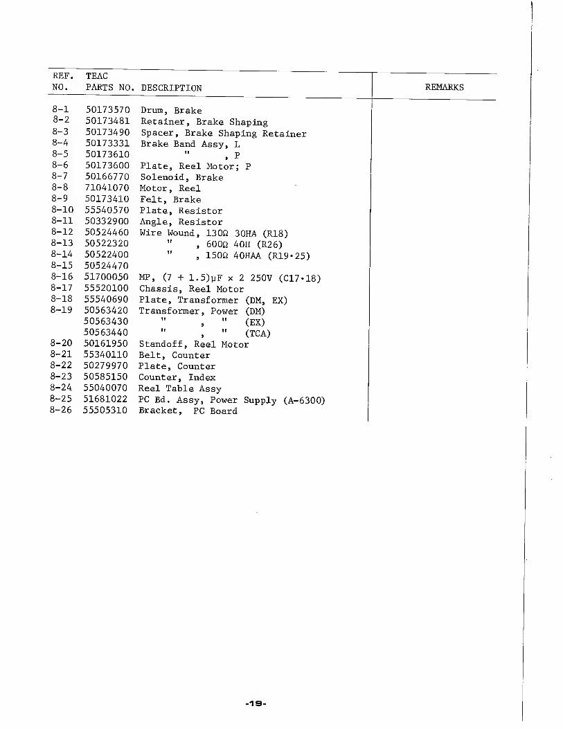
REF. NO.
TEAC PARTS NO. DESCRIPTION REMARKS
8-1 50173570 Drum, Brake 8-2 50173481 Retainer, Brake Shaping 8-3 50173490 Spacer, Brake Shaping Retainer 8-4 50173331 Brake Band Assy, L 8-5 50173610 " , P 8-6 50173600 Plate, Reel Motor; P 8-7 50166770 Solenoid, Brake 8-8 71041070 Motor, Reel 8-9 50173410 Felt, Brake 8-10 55540570 Plate, Resistor 8-11 50332900 Angle, Resistor 8-12 50524460 Wire Wound, 130ft 30HA (R18) 8-13 50522320 " , 600ft 4OH (R26) 8-14 8-15
50522400 50524470
" , 150ft 40HAA (R19-25)
8-16 51700050 MP, (7 + 1.5)yF x 2 250V (C17*18) 8-17 55520100 Chassis, Reel Motor 8-18 55540690 Plate, Transformer (DM, EX) 8-19 50563420
50563430 50563440
Transformer, Power (DM) " , " (EX) " , " (TCA)
8-20 50161950 Standoff, Reel Motor 8-21 55340110 Belt, Counter 8-22 50279970 Plate, Counter 8-23 50585150 Counter, Index 8-24 55040070 Reel Table Assy 8-25 51681022 PC Bd. Assy, Power Supply (A-6300) 8-26 55505310 Bracket, PC Board
19


REF. NO.
TEAC PARTS NO. DESCRIPTION REMARKS
9-1 50141842 Limit Stop, Pinch Roller 9-2 55240080 Spring, Return 9-3 50275690 Cushion, Rubber 9-4 55200620 Spring, Pressure; B 9-5 55640160 Arm Assy, Pinch Roller 9-6 51630040 Solenoid Assy, Pinch Roller 9-7 50141821 Shaft, Roller Arm 9-8 50422570 Diode, SIB01-06 (D18) 9-9 55541120 Plate, Lifter; B 9-10 (not used) 9-11 50221100 Spring, Lifter; A 9-12 55000740 Arm Assy, Lifter; R 9-13 50152501 Shaft, Lifter Arm 9-14 55040190 Lifter Assy, Cue 9-15 55541180 Arm, Cue 9-16 55440220 Shaft, Lifter Arm 9-17 55200030 Spring 9-18 50141751 Pinch roller 9-19 50142180 Cap, Pinch Roller 9-20 55200161 Spring, Pause Lock 9-21 55500270 Plate, Pause Lock 9-22 55040100 Guide Assy, Cue 9-23 55440330 Shaft, Guide 9-24 55440230 Stud, Cue 9-25 55040110 Linkage Assy, Cue 9-26 55305150 Lever, Cue 9-27 55305300 Hook, Cue Lever 9-28 55200030 Spring
■SI


REF. NO.
TEAC PARTS NO. DESCRIPTION REMARKS
10-1 50141842 Limit Stop, Pinch Roller 10-2 50220441 Spring, Return 10-3 50275690 Cushion, Rubber 10-4 55200620 Spring, Pressure; B 10-5 55640160 Arm Assy, Pinch Roller 10-6 50616691 Solenoid Assy, Pinch Roller 10-7 50141821 Shaft, Roller Arm 10-8 50529050 Spark Killer, O.lyF + 1200 400V 10-9 55540610 Plate, Lifter 10-10 50422570 Diode, SIB01-06 (D15) 10-11 50221100 Spring, Lifter; A 10-12 55000740 Arm Assy, Lifter, R 10-13 50152501 Shaft, Lifter Arm 10-14 55000730 Arm Assy, Lifter, L 10-15 50141751 Pinch Roller 10-16 50142180 Cap, Pinch Roller
23


REF. NO.
TEAC PARTS NO . DESCRIPTION REMARKS
11-1 55020041 Panel, Ampl. Trim (A-6100) 55020031 " , " (A-6300)
11-2 55020050 Chassis, Ampl. Assy; A (A-6100) 55020060 ", " ; B (A-6300)
11-3 50581470 VU Meter (A-6100) 50581480 " (A-6300)
11-4 55440581 Knob, Upper 11-5 55040350 " , B (A-6100)
55040340 " , Lower (A-6300) 11-6 55400821 Lock Nut 11-7 55200610 Washer, Wave 11-8 55340130 Guide, Memory Marker (A-6100)
55300750 " , " (A-6300) 11-9 55202270 11-10 50537100 VR, lOkfl, x 2; MIC/LINE 11-11 50537250 ", lOOkSJ A X 2; OUTPUT (VR501/504) (A-6100)
50537090 ", " ; " ( " ) (A-6300) 11-12 55040510 Cover, Lamp; PAUSE (Green) 11-13 55040520 ", " ; RECORD (Red) 11-14 55540660 Bracket, Lamp 11-15 50414600 Lamp, Pilot 11-16 50415241 Holder, Lamp 11-17 55530161 Bracket, SW 11-18 50443902 SW Assy, Selector, REEL/SPEED (SW509/S12-SW502) 11-19 50253530 Button, D 11-20 55340140 Button 11-21 50253880 Mask, SW 11-22 55501280 It It
»
11-23 55501161 Plate, Power SW 11-24 50443870 SW, Double Action; POWER (SI) (DM, EX)
50444500 ", " ; " ( ") (TCA) 11-25 55540650 Plate, Memory SW 11-26 50443940 SW, Push; MEMORY 11-27 50549920 Metalized Mylar, O.lpF 400V AC (A-6300) 11-28 50529050 Spark Killer, O.lpF + 1202 400V (DM, EX)
50529060 " , 0.033yF + 1202 400V (TCA) 11-29 50447450 SW, Lever; ATT (SW511) (A-6100) 11-30 55440400 Knob, Lever; C 11-31 55540760 Mask, SW; B 11-32 51681110 PC Bd. Assy, Mic. Attenuator 11-33 55300760 Insulator Mask, Jack 11-34 55300770 Bracket, Jack Mounting 11-35 50430240 Jack, Phone; 2-Wire, MIC 11-36 50432450 ", " ; 3-Wire, PHONES 11-37 55501191 Plate, Lever SW 11-38 55300800 Button, MONITOR 11-39 55501280 Mask, SW 11-40 50444640 SW, Miniature Push; MONITOR (SW501) 11-41 50939280 Clamp, B 11-42 50829850 Mak, SW 11-43 50447210 SW, Lever; 4PDT, RECORD MODE 11-44 50447220 ", " ; DPDT 11-45 50237291 Plate Nut, Retaining 11-46 50239300 Rubber Protector, P 11-47 50237201 Button, A [►] 11-48 50237211 " , B [m»] (A-6100)
55300721 " , FAST (A-6300) 11-49 50237221 " , STOP 11-50 55300731 " , REC 11-51 55300741 " , PAUSE 11-52 55340430 Hinge, A 11-53 55340440 " , B 11-54 50332720 Plate, Hinge Adjusting 11-55 50253870 Plate, Retaining
-as


REMARKS REF. TEAC
NO. PARTS NO. DESCRIPTION
12-1 55520130 Panel, Rear Connection, A (A-6100)
55520140 ", " , B (A-6300)
12-2 50436580 Jack, Pin; 4P
12-3 50233530 Plate, DIN Connector
12-4 50452060 Terminal Strip, 1L-2P
12-5 50430010 Connector, DIN
12-6 55300470 Grommet, AC Power Cord
12-7 50471652 Cord, AC Power (DM, EX)
50471661 " , " (TCA)
12-8 50924500 Fuse Holder (DM)
50412280 " (TCA)
12-9 50411140 Fuse, 2A (DM, EX 100*117V area)
50411010 " , 1A (EX*220 240V area)
50411340 " , 2A-250V (TCA)
12-10 55501151 Adaptor, Fuse Holder (DM, TCA)
12-11 50436590 Connector, 28P (Plug)
12-12 50436600 " , " (Socket)
12-13 55501270 Angle, PC Board
12-14 50432700 Socket, IIP
12-15 50433010 Plug, Dummy; IIP (A-6100)
50433000 ", " ; " (A-6300)
12-16 50454071 Post, Grounding
12-17 51681071 PC Bd. Assy, MIC/PB EQ Ampl. (A-6100)
51681351 " , " (A-6300)
12-18 50233760 Plate, PC Board
12-19 51681080 PC Bd. Assy, Line Out/Phone Ampl. (A-6100)
51681330 " , " (A-6300)
12-20 51681091 " , Record/Meter Ampl. (A-6100)
51681361 " , " (A-6300)
12-21 51681341 " , Bias Oscillator
12-22 55501240 Angle, PC Board
12-23 50435030 Voltage Selector, with Fuse (EX)
12-24 55501500 Mask, Fuse (EX)
12-25 51681051 PC Bd. Assy, Control Relay (A-6100)
51681011 PC Bd. Assy, Control Relay (A-6300)
12-26 55530141 Bracket, PC Board Re-inforcing, L
12-27 55530150 ", " , R
12-28 55400840 Spacer, A
12-29 50237160 "
12-30 50446560 SW, Micro; VV-15-1A
12-31 50446570 », " ; W-15-2A
12-32 50446580 ", «> ; W-15-3A
12-33 50440000 ", Slide (A-6100)
12-34 55540680 Angle, PC Board; P (A-6100)
12-35 51681371 PC Bd. Assy, Peak Level Indicator Ampl. (A-6100)
-37

13
REF. NO.
13-1 13-2 13-3 13-4 13-5 13-6 13-7 13-8 13-9
13-10
NOTE:
TEAC PARTS NO. DESCRIPTION
55980500 50276971
*RE-1002 50471250 57100300 50291860
50629620 50411010 50411140 50411340 50291350
Reel Clamp Adapters (TZ-612), x2 Rubber Feet (for Horizontal Use), Empty Reel, 10 inch Input-output Connection Cords, x2 Cleaning Stick (TZ-275) Oil and Applicator Sensing Foil Splicing Tape Fuse, 1A (EX 220, 240V area)
» , 2A (EX 100, 117V area) " , 2A-250V (TCA'UL)
Silicone Cloth
x4
51012560 A-6100 Instruction Manual (DM) 51012570 •' (EX) 51012580 » (TCA) 51012590 A-6300 Instruction Manual (DM) 51012600 » (EX) 51012610 » (TCA)
The Empty Reel is available as an Optional Accessory and thus is not assigned a special TEAC Parts number. Please order this by the MODEL CODE NUMBER (RE-702). This number is included on the package.
REMARKS
-28-

PRINTED CIRCUIT BOARD PARTS LIST A-G1 OO / A-63QO
-as-

To M
IC A
TT
1I. MIC/PLAYBACK EQ AMPLIFIER (A-61QQ)
-30-
To L
INE

CIRCUIT REF. NO
TEAC PARTS NO DESCRIPTION
51681071 PC Bd. Assy
51671070 PC Bd.
TRANSISTORS
Q101/Q104 50424710 2SC1345 i-E or F Q102/Q105 50424870 2SA763- YL Q103/Q106 50424600 2SC828- S Q107/Q109 50423840 FET, 2SK30-Y Q108/Q110 50424100 2SC100C i-GR
CARBON RESISTORS
R101/R120 50571380 220kfi 1/4W R102/R121 50570820 lk« It
R103/R122 50571240 56kS2 II
R104/R123 50571240 56kfl It
R105/R124 50571220 47kfi It
R106/R125 50571200 39kfi II
R107/R126 50571080 12kfi II
R108/R127 50570840 1.2kfi II
R109/R128 50571180 33kf2 It
R110/R129 50570840 1.2kU It
R111/R130 50570640 ison II
R112/R131 50571060 lOkfl II
R113/R132 50571000 5.6kfl II
R114/R133 50571380 220kfl II
R115/R134 50570840 1.2kfi II
R116/R135 50571460 470kfl II
R117/R136 50571320 120kfi II
R118/R137 50571320 120kfl II
R119/R138 50571260 68kfl II
R139 50570740 470J2 II
R140/R150 50571540 1M tl R141/R151 50571100 15k II
R142/R152 50570820 lkfl II
R143/R153 50573260 68kfi II
R144/R154 50571040 8.2kfi It
R145/R155 50571340 150kfi II
R146/R156 50571190 36kft II
R147/R157 50570940 3.3kO II
CIRCUIT REF. NO.
TEAC PARTS NO . DESCRIPTION
R148/R158 50570540 68ft ii R149/R159 50570820 lkft n
R160 50570660 220fi ii R170/R171 50570920 2.7kfl " R172/R173 50571240 56kft it
CAPACITORS
C101/C114 51700090 Tant. 10pF 16V C102/C115 50555540 Elec. 47yF 10V C103/C116 50547560 Dip. Mica 470pF 50V C104/C117 50549700 Elec. 10yF 25V C105/C118 50549740 11 lOOyF 25V C106/C119 50554230 II lOOyF 6.3V C107/C120 50543820 Dip. Mica 22pF 50V C108/C121 50547560 II 470pF 50V C109/C122 50549700 Elec. lOyF 25V C110/C123 50548480 Mylar 0.01yF 50V C111/C124 50546701 Dip. Tant. lyF 35V C112/C125 50546701 II lyF 35V C113/C126 50546682 II 0.47yF 35V
C127 50554170 Elec. lOOyF 25V
C128/C136 50548270 Mylar 0.047yF 50V C129/C137 50547430 Dip. Mica 51pF 50V C130/C138 50554900 Elec. 22yF 35V C131/C139 50554050 II lOyF 16V C132/C140 50547430 Dip. Mica 51pF 50V C133/C141 50554040 Elec. lOyF 25V C134/C142 50554040 II lOyF 25V C135/C143 50554230 II lOOyF 6.3V
C144 50554180 II 220yF 25V
VARIABLE RESISTORS
VR101/103 50533580 Trimmer 6 8kfi B VR102/104 50533580 " 6 8kfi B
MISCELLANEOUS
J101/J102 50435000 Pin Jack
31

2. MIC/PLAYBACK EQ AMPLIFIER CA-B3QOJ
-3a-
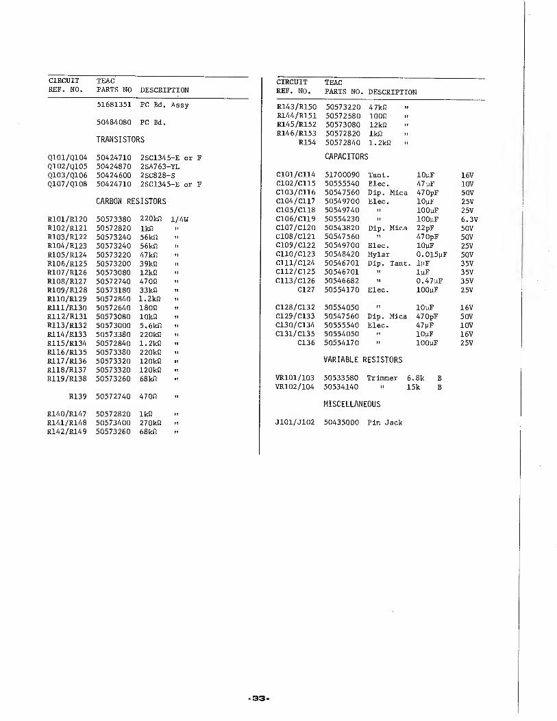
CIRCUIT REF. NO.
TEAC PARTS NO DESCRIPTION
CIRCUIT REF. NO.
TEAC
PARTS NO DESCRIPTION
51681351 PC Bd. Assy R143/R150 50573220 47kl2 R144/R151 50572580 10012 ii
50484080 PC Bd. R145/R152 50573080 12kl2 " R146/R153 50572820 lk!2 ii
TRANSISTORS R154 50572840 1.2kl2
Q101/Q104 50424710 2SC1345-E or F CAPACITORS
Q102/Q105 50424870 2SA763-YL Q103/Q106 50424600 2SC828-S C101/C114 51700090 Tant. lOpF 16V Q107/Q108 50424710 2SC1345-E or F C102/C115 50555540 Elec. 47pF 10V
C103/C116 50547560 Dip. Mica 470pF 50V
CARBON RESISTORS C104/C117 50549700 Elec. lOpF 25V C105/C118 50549740 II lOOpF 25V
R101/R120 50573380 220kl2 1/4W C106/C119 50554230 It lOOpF 6.3V R102/R121 50572820 lkfl C107/C120 50543820 Dip. Mica 22pF 50V R103/R122 50573240 56kl2 " C108/C121 50547560 II 470pF 50V
R104/R123 50573240 56kl2 >■ C109/C122 50549700 Elec. lOpF 25V R105/R124 50573220 47kl2 " C110/C123 50548420 Mylar 0.015pF 50V
R106/R125 50573200 39kl2 ■> C111/C124 50546701 Dip. Tant. lpF 35V
R107/R126 50573080 12kl2 •' C112/C125 50546701 II lpF 35V
R108/R127 50572740 47012 C113/C126 50546682 II 0.47pF 35V
R109/R128 50573180 33kl2 t. C127 50554170 Elec. lOOpF 25V
R110/R129 50572840 1.2kl2 i"
R111/R130 50572640 18012 " C128/C132 50554050 II lOpF 16V
R112/R131 50573080 lOkfl ii C129/C133 50547560 Dip. Mica 470pF 50V
R113/R132 50573000 5.6kl2 ii C130/C134 50555540 Elec. 47pF 10V
R114/R133 50573380 220kl2 ii C131/C135 50554050 II lOpF 16V
R115/R134 50572840 1.2kl2 » C136 50554170 II lOOpF 25V
R116/R135 50573380 220kl2
R117/R136 50573320 120kl2 .1 VARIABLE RESISTORS
R118/R137 50573320 120kl2 ii
R119/R138 50573260 68kS2 ii VR101/103 50533580 Trimmer 6 8k B VR102/104 50534140 " 15k B
R139 50572740 47012 ii
MISCELLANEOUS
R140/R147 50572820 lk!2 ii
R141/R148 50573400 270kl2 ii J101/J102 50435000 Pin Jack
R142/R149 50573260 68kl2 ii
33

3. LINE OUT PHONE AMPLIFIER CA-61QO)
L ch R ch OUTPUT VR OUTPUT VR
MONI SW PHONES MONI SW

CIRCUIT REF. NO
TEAC PARTS NO DESCRIPTION
51681080 PC Bd. Assy
51671080 PC Bd.
TRANSISTORS
Q201/Q204 50423770 2SC644- -T Q202/Q205 50424870 2SA763- -YL Q203/Q206 50424600 2SC828- -S
CARBON RESISTORS
R201/R220 50572820 lkft 1/4W R202/R221 50573260 68kft II
R203/R222 50573220 47kft II
R204/R223 50573260 56kft II
R205/R224 50573140 22kft II
R206/R225 50573060 lOkft It
R207/R226 50572800 820ft It
R208/R227 50573240 56kft II
R209/R228 50572760 560ft II
R210/R229 50572580 100ft II
R211/R230 50572980 4. 7kfi II
R212/R231 50573120 18kft II
R213/R232 50572820 lkft II
R214/R233 50573160 27kft II
R215/R234 50573280 82kft II
R216/R235 50573080 12kft II
R217/R236 50572940 3.3kft II
R218/R237 50572760 560ft II
R219/R238 50573380 220kft II
R239 50570620 150ft II
CIRCUIT REF. NO.
TEAC
PARTS NO. DESCRIPTION
R251/R253 50573220 39kft R252/R254 50573240 56kft 'i
CAPACITORS
C201/C214 50549660 Elec. IpF 25V C202/C215 50546562 Dip. Tant. lOpF 16V C203/C216 50548320 Mylar 0. 01pF 50V C204/C217 50554050 Elec. lOpF 16V C205/C218 50548020 Mylar O.OOlpF 50V C206/C219 50554260 Elec. 33pF 16V C207/C220 50547440 Dip. Mica lOOpF 50V C208/C221 50554230 Elec. 100PF 6.3V C209/C222 50543820 Dip. Mica 22pF 50V C210/C223 50549700 Elec. lOpF 25V C211/C224 50554050 It lOpF 16V C212/C225 50554260 tt 33pF 16V C213/C226 50555540 II 47pF 10V
C227 50554170 It lOOpF 25V
VARIABLE RESISTORS
VR201/203 50533590 Trimmer 3. 3kft B VR202/204 50534120 >■ 33kft B
COILS
L201/L202 50566640 Coil, Choke 220PH
TRANSFORMERS
T201/T202 50562141 3kft: 8ft
-35-

LINE OUT PHONE AMPLIFIER CA-6300)

CIRCUIT REF. NO.
TEAC
PARTS NO. DESCRIPTION CIRCUIT REF. NO.
TEAC PARTS NO. DESCRIPTION
51681330 PC Bd. Assy CAPACITORS
50484090 PC Bd. C201/C214 50549660 Elec. lpF 25V
TRANSISTORS C202/C215 50546562 Dip. Tant. lOyF 16V C203/C216 50548320 Mylar O.OOlpF 50V
Q201/Q204 50423770 2SC644-T C204/C217 50554050 Elec. lOyF 16V
Q202/Q205 50424870 2SA763-YL C205/C218 50548020 Mylar O.OlyF 50V
Q203/Q206 50424600 2SC828-S C206/C219 50554260 Elec. 33yF 16V C207/C220 50547440 Dip. Mica lOOpF 50V
CARBON RESISTORS C208/C221 50554230 Elec. lOOpF 6.3V C209/C222 50543820 Dip. Mica 22pF 50V
R201/R220 50572820 lkfi 1/4W C210/C223 50549700 Elec. lOyF 25V
R202/R221 50573260 68kfl » C211/C224 50554050 II lOyF 16V
R203/R222 50573220 47kfl " C212/C225 50554260 II 33yF 16V
R204/R223 50573260 56kft " C213/C226 50555540 II 47yF 10V
R205/R224 50573140 22kfl " C227 50554170 II lOOyF 25V
R206/R225 50573060 lOkO " R207/R226 50572760 560S2 " VARIABLE RESISTORS
R208/R227 50573240 56k£2 " R209/R228 50572760 5600 » VR201/203 50533640 Trimmer 2. 2kO B
R210/R229 50572580 lOOfl " VR202/204 50534120 " 33kfl B
R211/R230 50572980 4.7kO ■' COILS R212/R231 50573140 22kO
R213/R232 50572820 lkfl 11
L201/L202 R214/R233 50573160 27kO " 50566640 Coil, Choke 220yH
R215/R234 50573280 82kfl " R216/R235 50573080 12kfi " TRANSFORMERS
R217/R236 50572940 3.3kO " R218/R237 50572760 5600 T201/T202 50562141 3kfi: 8fi
R219/R238 50573380 220kfi R239 50570620 1500
-37.

5. RECORD/METER AMPLIFIER (A-BIOO)
m

CIRCUIT REF. NO.
TEAC
PARTS NO . DESCRIPTION CIRCUIT REF. NO.
TEAC
PART NO. DESCRIPTION
51681091 PC Bd. Assy R380/R381 50571120 18kfi It
R382/R383 50571220 47kfi II
51671090 PC Bd. R384/R385 50571260 68kfi II
TRANSISTORS CAPACITORS
Q301/Q305 50423770 2SC644-T C301/C325 50554050 Elec. lOyF 16V Q302/Q306 50424870 2SA763-YL C302/C326 50555540 It 47 yF 10V Q303/Q307 50423770 2SC644-T C303/C327 50547560 Dip. Mica 470pF 50V Q304/Q308 50424870 2SA763-YL C304/C328 50549700 Elec. lOyF 25V Q309/Q310 50424820 2SC828-S C305 50554170 II lOOyF 25V
C306/C330 50554910 II 220yF 10V CARBON RESISTORS C307/C331 50543820 Dip. Mica 22pF 50V
C308/C332 50547450 It 220pF R301/R332 50570820 lk£J 1/4W C309/C333 50548270 Mylar 0.047yF 50V R302/R333 50571240 56kf2 II C310/C334 50546651 Dip. Tant . 0.15yF 35V R303/R334 50571240 56kO It C311/C335 50554050 Elec. lOyF 16 V R304/R335 50571220 47kO It C312/C336 50548260 Mylar 0.0056yF 50V R305/R336 50571200 39kfl It C313/C337 50554050 Elec. lOyF 16V R306/R337 50571080 12kO It C314/C338 50555540 II 47 yF 10V R307/R338 50571220 39kfl It C315/C339 50547560 Dip. Mica 470pF 50V R308 50571180 33k0 It C316/C340 50549700 Elec. lOyF 25V R309/R340 50570720 3900 II C317/C341 50554910 II 220yF 10V R310/R341 50570540 680 It C318/C342 50543820 Dip. Mica 22pF 50V R311/R342 50570940 3.3kO II C319/C343 50554050 Elec. 10 yF 16V R312/R343 50571220 47kO II C320/C344 50548131 Mylar 0.0047yF 50V R313/R344 50571300 lOOkO II C321/C345 50543440 Polyst. 820pF 50V R314/R345 50571140 22kO II
R315/R346 50571120 18kO II C323/C347 50548810 Mylar 0.0033yF 50V 5% R316/R347 50571120 18kO II C324/C348 50548970 II 0.018yF 50V 5%
R317/R348 50570820 lkfl II
R318/R349 50571380 220k0 II C349 50554170 Elec. lOOyF 25V R319/R350 50571300 lOOkO II C350/C354 50555470 II lyF 25V R320/R351 50571220 47kO II C351/C355 50554570 II lOOyF 10V R321/R352 50571140 22kO II C352/C356 50555470 II IMF 25V R322/R353 50571060 lOkO II C353/C357 50548320 Mylar O.OOlyF 50V R323/R354 50570860 1. 5kO II
R324/R355 50572760 5600 II C380/C381 50554050 Elec. 10 yF 16V R325/R356 50572580 1000 II C382/C383 50548780 Mylar O.OOlyF 5% R326/R357 50570920 2.7kO II C384/C385 50548780 II 0.001 yF 5% R327/R358 50570820 IkO II
R328/R359 50571220 47kO II VARIABLE RESISTORS
R330/R361 50570540 680 II VR301/304 50534120 Trimmer 33k« B R331/R362 50570820 IkO II VR302/305 50534120 It II II
R363 50570620 1500 II VR303/306 50534120 II II M
VR307/308 50533490 II lOOkO t. R364/R370 50571100 15kO II
R365/R371 50571280 82kO II COILS R366/R372 50571140 22k0 II
R367/R373 50570960 3.9kO II L301/L303 50566670 Record EQ 1.5-2.4mH R368/R374 50570820 IkO II L302/L304 50566300 Trap 3mH R369/R375 50570560 820 II
-39'
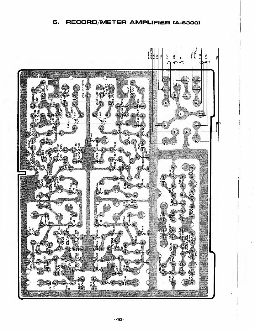

CIRCUIT REF. NO
TEAC PARTS NO DESCRIPTION
CIRCUIT REF. NO.
TEAC PARTS NO DESCRIPTION
51681361 PC Bd. Assy R349/R355 50571280 82kfi II
R350/R356 50571140 22k a It
50484401 PC Bd. R351/R357 50570960 3.9kfi II
R352/R358 50570820 lkfl II
TRANSISTORS R353/R359 50570560 82fl II
R360/R361 50570600 120fl It
Q301/Q305 50423770 2SC644-T Q302/Q306 50424870 2SA763-YL CAPACITORS Q303/Q307 50423770 2SC644-T Q304/Q308 50424870 2SA763-YL C301/C316 50554050 Elec. lOyF 16V Q309/Q310 50424820 2SC828-S C302/C317 50548320 Mylar O.OOlyF 50V
C303/C318 50554050 Elec. lOyF 16V CARBON RESISTORS C304/C319 50555540 II 47yF 10V
C305/C320 50549770 II lOyF 16V R301/R324 50570820 lkfl 1/4W C306/C321 50548540 Mylar 0.0068yF 50V R302/R325 50571340 150kfi C307/C322 50554050 Elec. lOyF 16V R303/R326 50571260 68kQ C308/C323 50554050 IT lOyF 16V R304/R327 50571020 6.8k& t» C309/C324 50555540 It 47yF 10V R305/R328 50571120 18kft C310/C325 50554050 II lOyF 16V R306/R329 50570720 390J2 h C311/C326 50548310 Mylar 0.15yF 50V R307/R330 50570540 68fi n C312/C327 50548420 II 0.015yF 50V R308/R331 50570940 3.3kR .. C313/C328 50548290 II 0.022yF 50V R309/R332 50571220 47kfi i. C314/C329 50548131 II 0.0047yF 50V R310/R333 50571060 lOkfl n C315/C330 50543440 Polyst. 820pF 50V R311/R334 50570960 3.9kf2 i. C331 50554170 Elec. lOOyF 25V R312/R335 50571380 220kf2 C332/C336 50555470 II lyF 25V R313/R336 50571300 lOOkfi u C333/C337 50554570 It lOOyF 10V R314/R337 50571060 lOkft *i C334/C338 50555470 It lyF 25V R315/R338 50571140 22kfi i. C335/C339 50548321 Mylar O.OOlyF 50V R316/R339 50570860 l.Skfl i. R317/R340 50570760 560fi ii VARIABLE RESISTORS R318/R341 50570580 lOOfi ii R319/R342 50570980 4.7kfl ti VR301/304 50533520 Trimmer 47kfi B R320/R343 50571100 15kfl .. VR302/305 50533520 II 47k« B R321/R344 50571260 68kfl ii VR303/306 50534120 It 33kfl B R322/R345 50570580 lOOfl ii
R323/R346 50570820 lkft n COILS R347 50570620 150« ii
R348/R354 50571100 15kfi ii L301/L303 50566370 Record EQ 2.4-4.2mH L302/L304 50566300 Trap 3mH

CIRCUIT REF. NO.
TEAC
PARTS NO. DESCRIPTION
51681051 PC Bd.
REMARKS
51671051 PC Bd.
SEMICONDUCTORS
Q3
D10-D13 D14
D15-D17
50424620 50422560 50422570
50422560
Transistor, 2SD235-Y Diode, S1B01-02
" S1B01-06
'• S1B01-02
RELAYS
K1*K4 50611180 DC 24V 4PDT K2-K7 50611170 " SPDT K3 50611140 " DPDT K5 50611150 " SPDT K6 50611130 DC 12V SPDT
RESISTORS
R14 50575140 Carbon 22kft 1/2W 5% R15 50575040 II 470ft II II
R16 50575060 II lOkft II II
R17 50574260 II 47ft II It
R18 50527140 Metal Oxide Film, 470ft 3W R19 50526120 Wire Wound, 10ft 1W
CAPACITORS
C12-C14 50554980 Elec • 2.2pF 50V C13 50554620 II 470pF 35V C15 51700070 II lOOyF 35V C16 51700580 It 22yF 50V C17 50554890 II lOOOyF 16V C901-913 50549920 Metalized Mylar O.lyF 400V CR901-906 50529050 Spark Killer O.lyF + 120ft 400V
MISCELLANEOUS
J3 50436590 Connector, 28P (Plug) 50436600 II II (Socket) 50436530 » 15P (Plug) 50438310 If II (Socket) 50436680 " 3P (Plug) 50436690 11 II (Socket)
l
-43-

44

CIRCUIT REF. NO.
TEAC PARTS NO. DESCRIPTION REMARKS
51681011 PC Bd. Assy Control Relay
51671011 PC Bd. , Control Relay
SEMICONDUCTORS
Q3 50424600 Transistor, 2SC828-S D7-D12-D16 50422560 Diode, S1B01-02 D13 50422970 tt
SR3AM-6 D14 50422560 II S1B01-02 SCR1 50428040 Thyristor, F0R2B41
RELAYS
K2•K4•K5 50611180 DC 24V 4PDT K6*K9"K12 50611150 " SPOT K7 50611170 " SPDT
RESISTORS
R8 50526280 Wire Wound 150ft 1W R9 50575060 Carbon lOkft 1/2W RIO 50526120 Wire Wound 10ft 1W Rll 50525320 II
100ft " R12 50515460 Carbon 5.6kft 1/4W R13 50571000 II
15kft R14-R15 50515340 II lkft
CAPACITORS
C7 50554750 Elec. 33yF 35V C8 50555690 II lOyF 35V C9 51700580 If 22yF 50V CIO 50554620 II 470yF 35V Cll* C12 50551380 II lOOOyF 35V C13 50554850 If 22yF 6.3V C14 50554900 ft
22yF 35V C901-911 50549920 Metalized Mylar O.lyF 400V CR901-903 50529050 Spark Killei O.lyF + 120ft 400V
MISCELLANEOUS
J3 50436590 Connector, 28P (Plug) 50436600 II
" (Socket) 50436530 It
15P (Plug) 50438310 fl
" (Socket) 50436660 If
5P (Plug) 50436670 tl " (Socket)
45-

S. POWER SUPPLY CA-GIOO]

CIRCUIT TEAC REF. NO. PARTS NO. DESCRIPTION REMARKS
51681062 PC Bd. Assy
51671061 PC Bd.
55505300 Heat Sink 50332910 Sheet, Insulating 50332950 Tube, Insulating 50411360 Fuse, 2A
SEMICONDUCTORS
Ql 50424620 Transistor, 2SD235-Y Q2 50424820 ft 2SC828-S D1-D8 50422560 Diode, SIB01-02 D9 50422570 ti SIBO1-06 DZ1 50422980 Diode, Zener; 02Z9-1A
RELAYS
K11-K13 50611140 DC 24V, 3PDT K12 50611120 •• DPDT
RESISTORS
R1 50525440 Wire Wound 3.3 Q R2 50515380 Carbon 2.2kfl R3 50515470 11 6.8kn R4 50515360 II 1.5kn R5 50515330 II 820fi R6 50526120 Wire Wound ion R7 50526270 II 47ft R8 50526150 II o.5n R9 50520340 Cement 1.5Q
CAPACITORS
C1*C2«C4 50554990 Elec. 330pF C3 50554630 II lOOpF C5 50554620 If 470pF C6 50555660 11 2200pF C7* C8 50551380 11 lOOOpF C701- 709 50549920 Metalized Mylar O.lpF CR701-703 50529050 Spark Killer o.ipF + :
VARIABLE RESISTOR
VR1 50533760 Trimmer 330n B
-47-


CIRCUIT REF. NO.
TEAC PARTS NO. DESCRIPTION
51691022 PC Bd. Assy, Power Supply
51671021 PC Bd. Power Supply
55505300 Heat Sink 50332910 Sheet, Insulating 50332950 Tube, Insulating
F3 50411360 Fuse, 2A
SEMICONDUCTORS
Q1 50424620 Transistor, 2SD235-Y Q2 50424820 ft 2SC828-S D1-D6 50422560 Diode, SIB01-02 DZ1 50422980 Diode, Zener; 02Z9-1A
RELAYS
K1-K3-K10 50611180 DC 24V, 4PDT
Kll 50611180 t> 4PDT
RESISTORS
R1 50525440 Wire Wound 3.3ft 1W R2 50515380 Carbon 2.2kft R3 50515470 ft 6.8kft R4 50515360 II 1.5kft R5 50515330 If 820ft R6 50526120 Wire Wound 10ft 1W R7 50526270 II 47ft
CAPACITORS
C1*C2*C4 50554990 Elec. 330yF 50V C3 50554630 II lOOyF 35V C5 50554620 If 470yF 35V C6 50551380 II lOOOyF 35V C701 50549920 Metalized Mylar O.ly 400V CR701-723 50529050 Spark Killer O.lyF + 120ft
VARIABLE 1 RESISTOR
VR1 50533760 Trimmer 330ft B
REMARKS
400V
-49

BIAS OSCILLATOR
51681341 PC Bd. Assy C402 50549920 Mylar O.lyF 400V
C403 50548810 II 0.0033yF 50V
50484413 PC Bd. C404 50548810 II 0.0033yF 50V
C405 50548930 II 0.0068yF 50V
TRANSISTORS C406 50544040 Mica. 4200pF 250V
C407 50548740 Mylar 0.022yF 150V
Q401/Q402 50424450 2SC1226A-P C408 50555000 Elec. 3.3yF 35V
RELAY VARIABLE RESISTOR
K401 50611180 DC 24V, 4PDT VR401 50539020 Trimmer 200H B
CARBON RESISTORS TRIMMER CAPACITORS
CIRCUIT TEAC
REF. NO. PARTS NO. DESCRIPTION
CIRCUIT TEAC REF. NO. PART NO. DESCRIPTION
R401 50514920 2.2kfi 1/2W
R402 50515210 lOOfi 1/4W R403/R404 50574900 2.2kfi 1/2W
R405/R406 50574480 39fl
R407 50515190 56f2 1/4W
R411/R412 50570340 lOfi
CAPACITORS
C401 50554380 Elec. 220yF 35V
VC401/402 50547070 MAX. 80pF
COILS
T401 50563170 Coil, Bias Osc.
L401 50566581 Coil, Dummy 3mH
MISCELLANEOUS
50330930 Sheet, Insulating
50330940 Tube, Insulating

IS. TERMINAL PC BOARD
CIRCUIT REF. NO.
TEAC PARTS NO. DESCRIPTION
CIRCUIT REF. NO.
TEAC PARTS NO. DESCRIPTION
51681030 PC Bd. Assy (A-6300) R20 50515490 lOkfi 1/4W 51681040 11 (A-6100) R21 50515300 470fi II
R22 50515340 lkfl II
51671030 PC Bd. (A-6100/A-6300) R23 50515620 68kf2 II
R24 50515170 33fi II
TRANSISTORS
CAPACITORS Q5 50423510 2SC733-Y (A-6300) Q6 50424340 2SC1000-BL ( " ) C751 50549920 Metalized Mylar (A-6300)
O.luF 400V CARBON RESISTORS CR751-754 50529050 Spark Killer (A-6100/A-6300)
O.lyF + 120fi 400V R17 50574660 220£2 1/2W (A-6300)

3. PEAK LEVEL INDICATOR AMPL
CIRCUIT REF. NO.
TEAC PARTS NO. DESCRIPTION
CIRCUIT REF. NO.
TEAC PARTS NO. DESCRIPTION 1
51681371 PC Bd. Assy R811/R812 50572780 680R 11
R813/R814 50573060 lOkR 11
51671100 PC Bd. R815/R816 50573200 39kfi II
R817/R818 50573060 lOkR II
TRANSISTORS R819/R820 50573100 15kR II
R821/R822 50573060 lOkfi II
Q801/Q802 50424340 2SC1000-BL R823/R824 50572900 2.2kR It
Q803/Q804 11 11 R825/R826 50573120 18kfl 11
Q805/Q806 M 11 R827/R828 50573120 18kf2 II
R829/R830 50572900 2.2kfl 11
DIODES R831 50572580 100R 11
R833/R834 50572980 4.7kfi 11
D801/D802 50422440 S3016R
D803/D804 50422130 IN 60 CAPACITORS
CARBON RESISTORS C801/C802 50554050 Elec. lOyF 16V
C803/C804 50554050 11 lOyF 16V
R803/R804 50573300 lOOkfi 1/4W C805/C806 50554040 11 lOyF 25V
R805/R806 50573320 120kR 11 C807/C808 50554040 11 lOyF 25V
R807/R808 50572980 4.7kR 11 C809/C810 50559090 Bi-polar 4.7yF 25V
R809/R810 50572880 1.8kfi If C811 50554380 Elec. 220yF 35V
-52-

14. MIC ATTENUATOR
OdB
P-090
CIRCUIT TEAC REF. NO. PARTS NO. DESCRIPTION REMARKS
51681110 PC Bd. Assy
51671110 PC Bd.
CARBON RESISTORS
R601/R604 50571160 27kft 1/4W R602/R605 50570980 4.7kft II
R603/R606 50570840 1.2kJ2 ft
-53-

E. HEAD L Ch
15. HEAD PC BOARD
4T PLAY HEAD- L ch
2T PLAY HEAD-
L Ch
4T PLAY HEAD—
Rch
2T PLAY HEAD- R ch
REC-HEAD L ch
REC. HEAD
R ch
PLAY REV
HEAD Rch
PLAY REV
HEAD L ch
PLAY FWD HEAD Rch
PLAY FWD HEAD L ch
CIRCUIT REF. NO.
TEAC PARTS NO. DESCRIPTION
51681380 PC Bd. Assy (A-6300)
51681390 PC Bd. Assy (A-6100)
50483080 PC Bd. (A-6300) 51671120 PC Bd. (A-6100) 50444720 SW, Slide II
K8 50611210 Relay, Head Selector (A-6300) R28 50515340 Carbon lkft 1/4W II
C32 50554510 Elec. lOyF 35V II
REMARKS
-54-

HARDWARE NOMENCLATURE
All screws conform to ISO standards, and have cross-recessed heads, unless otherwise noted. ISOscrews have the head inscribed with a point as in the figure
to the right.
FOR EXAMPLE:
BM3x6
Length in mm (L)
Diameter in mm (D)
■ Type of Head
MACHINE SCREW
WOOD SCREW
SEMS SCREW
Abbreviation Full Name
R Round Head Screw
p Pan Head Screw
T Stove Head Screw (Truss)
B Binding Head Screw
Flat Countersunk Head Screw
Oval Countersunk Head Screw
Round Head Wood Screw
Flat Countersunk Wood Screw
Oval Countersunk Wood Screw
Binding Head SEMS Screw(A Type)
Binding Head SEMS Screw(B Type)
Binding Head- SEMS Screw(F Type)
Pan Head SEMS Screw(A Type)
Pan Head SEMS Screw(B Type)

TEAC
f ■
TEAC CORPORATION 3-7-3 NAKA-CHO, MUSASHINO, TOKYO PHONE: (0422) 53-1 HI
>
TEAC CORPORATION OF AMERICA 7733 TELEGRAPH ROAD, MONTEBELLO, CALIFORNIA 90640 PHONE: (213) 726-0303
v___ J
PRINTED IN JAPAN 0478 SYU 0.4

ii=? 8
oooopo oppooooo
CJ OT DO 03 CO CO T)3J2(/lZm3’0 C J. ID J, J. J, ID ro (D O (D —■ —1 —' 3 oi n pi DI 9 9 f) rt C 1+ 9 ffl 9 ,3 « O W »l W 7T O ID 1 ID k ^ .3 __ i ■( o i crtrcr 'Hft“I 5* > l—O. ID 9 9 9
p ~s t p-p. eu i— i— o o n o 9 m90,u 3rIDI—(DA-TrTr -'■T3 /D-O • • TJ <T> < ID < —1 **—» < it < id rnm
po —■ rit -"it -iitoo -—ID —' —■ <
< t* ro —* co fD Cb CL > Cl —‘U3C0
aj 5 -? 1^2 *5 Kg
popopo—j—1 OOO —‘OOOp WW^OIOOlUlS
UIWMMWMWW 0>007^0^p
woi^ooromu 03 CO -p. O CO CO A
- I-1 x* ADO S2?
VA<N * * II ^ lH :
LiLhUiSuii -? ? | CIQ410/25V(K(J) I f=i
ill sirX's?iC0
R345 VR304
C3B3 | R346 VR305
| C3BS |
R383 VR306
2 O R35?
_ _
If | p
1
-vR
l60
I
1? "f? ! 1
—'J/v-j
11 1 i z
9—--9-
m2*
s gJj r5 <ia Bil
R302 «
OI X
s§
?ku. $4. 47k —
IT?.” f:
56k
i Li s]l<l ja
[-cMP roK
sit! k I0/25V(KU)
. IN
■oS
—\W-
1 t O W| TT306 ; I w 0 L—41—
^ 220/iov
^P^3I068 R309390
Is is _1 5
JjllXS sia s SsK' 1 22k T® 5T
IS 1—If— si 2" 1C382 0.001 1
RSIBISk
ET<T r Ss HH 2” IC384 0.001 1
R384 68k
a glo 71 > oX<d
IPS .Pjva.10.0k . _f *
fot OJ S
T R320 47k
T ?215
'nj »5 a gs og
Ip W R3a22k| 47OP ✓'K
R3SiyN ^ lc3IS IO/25V(ku)
p% ij
j c
H fiio/lov
*R324560
m To <0 "
r 1_... >
1=0 I?o
!ijls s Mr? i
C349 —)\-
_RI32 Rii3 5.6k"^<e | Kl R(i4220k£TC' — -WV-1—
CII30-47/35V? $
I o
" < 5 CD . § UToi
< \J o.
JLiiiL
f-g si'? 55 2= iTS\[=l °5
° »i8§8
fafer 'i:
I-VA-Wv— VR204 R23B
?o5 @ ooJL t§o
O® (7T1 ’r"'
S *]ul . _L. J.S]._.
wa» i mXG R364t5k SgiST8 R3B5 02K
“rioo/iov«'I -II——1
C353 0-001
R4oi 2.2k(1/2W) R402
CBOI10/I6V Rajs4.7kl -M——-VA-C
, R803
4k ;o 3T° S'
'0 -S 00 S 0 61 <
Ck- Rao9l.8k PT
IJ ii 0 rip
og 0, ;g it
f 1 -2 sg 'S 's
I s?| 0 CO 8
ft 0 5J_ ,® roffi® a"
If r5S L8S 0 ™S
§ V
-U 2.2k
-i-:uj
©©©®©©©©0©©©Gvyy VV ▼▼▼ VYttYTTtVt
■H

NOIXVHOcJHOO
, 00£9'W X33HS'-ON H3COW
IdDdSNVdl 3dVi
■noyiNoo yawn-
a6cii.0A X'l.ddns 3v sapeo.Lpui :- 9614 [oa A|ddns qq sapeoipui :-
(pazLd-iaua-ap) apoui jois ui UMops s/Ce|au 14V uo.14.1sod zh 09 spd ul uMops popiMS uoLsuaAUOQ Aouanbajj
ase/ee^o
->1- sx (A3dl (MI)OSI sa
i—o—1 000 >—O—--AAA/
(nXlASE/0183
-)l- !3d0)
—o-£- r- 01 >1 uavis)
-o-vflflfty—jp-©-1 OS/dZZSO
’---)l-1
wO — (vT)0—a QQQ^—O-VW~— 7£ M3HKM (*3/11X01 «a ,(_
(A3UJEX si ~ " 1—o—kSS&j—*-©—1 oin
tlZ*ASE/OOQlsl 'IQ
r*n
--
Z>| (AV130) N 6063 ■ ■ 1 O—\OOQf~K3 " 1 (A3U) ZiX
—O—vOOP-r-O--<>— iMdSVd) _ sa
>—o-^asLr-+-©- w 1
ASg/22»0 ^
(*iloioia * s*{
«'—^—
AS£/0l” OI0
_ _
fm
i “L
i
i 1
_
Hifi'aJ- ' >1913 2'8
MSI £18
(S)8285S2^ ■-)|
[910
A£‘9/rt^2 £'0 , ««ri H|W8
-90-l09ls/ot,S 9z0cV —
,a koJ4i° OOE9-V/OOS^-VrZ
SOfr££-V/OOI9‘V S00£2-V/S00££-V= I £S
6S '"l—...r\ n
o !c 2-CN ,—11—L-
5* t\i
__
klQSNViSdVO
,“ios a»vae
j ^ ^SZ^
I3ZIS 33391 T
-™ * X inazaoj imps *
r loyiNoo "1 lyawii/jiqwayj
d/TA on
fla l*>
woaa/asvaa
xQV3H_. asvaal
■ r
ism 01
(9NISN3S) O—\SlSL/ >! •
9M I 0*
—u 1 n ISOd 20-I09IS HO 0NISN3S-
At>20a 01
>-r AI920Q
8010 W 1338
IS id31 #» EW
8010W 1338 -CIS 1H9I8 - 2W
---1 '-2* o - -@ ■"■■l-A11111—
*'»o 5s—;;
** USD “ ES o_-- --)|-- IAA3/D0Z2 ,JL ASE/000190
-®--XJr 23 1—r _eg a ; :»«
*».»■■ ■■■ -Tgl 1 1 Is L^. 5s S°1 3"t(
ffi (SW42I ,a|™rn 7
i> *Is wlSdW4 i~o_ T \/V) iS I® oi$I_I 991 X-X > 0> <0 _‘ Nd9 1HM _
- T | 1 £ L ASlr 3 f=> AO na)oooiDS2 90 U)££iosz so 19 zo . rz~ Z _ —■—- —H—o-~) -
vr6Z2Q ‘ZQ jAZ'92| s t- o EA9S ^oao
Hh if?
-Xk~i k fzrf3— Z M < O' 1 > Q - -
/4P\ 9 5A022u
W— - (MlUfrAii IS8280S2 so (A)SJ2(!S375 OWIEE'U 10 |(
•(MOOHM 1 ^lATgill |A9Z£.| 50ttip)-1 * A083k
® * e-sT^-rk —%-°TjZ J -()- © ’•-">iL(>_lJ aooidv
20683 90Z8311 |
a “k)-4
----1-1 osi» I _ o
] E06a:> A i-i» z-oi>j
* VH83' ■
” n * -—Wv-1 »-£>l U0SlVVH0fr«28# <
I- UO£IVHO£8'8 *"»>
-1 iuosiWHOfreia 9 I-IIM ’
8010W I NVlSdV3 |
m /-\ 1-E1S £9 '
--- | /— SI180 \
I2Z80 ^
suao
81180
£S °1 I
MS A133VS1
9* ^ r*1-! I_I
drfe-o+arfg 913
A8QDV
A080V-
A8S 0 V
A08 0V
fNialMOd OVll <===> I
° o [3SM]
[aoiofijC I?w3o/3
—oSo 0»3hJ -O-S^/ 039
^^0«dJ
30A3^
^^GMdJ
0W3H AV3d
_aino laaoiAi voi_ aoj wvaovia
C:a/£0°i
A00t//U03l+EE0
so/™ 01
iHM^VS-10'W r&O—--—*-Q-«o- gAO *Z__ I,3iA0 I M3MOc
A8S I -I |>| 01
mo- gA08 1-HM oi
^00?*-»>I01
®^ Llsna.
-A3NO 33Q01AJ NWdVr dOJ lAlVdOVIQ
is683 sa/ca oi
1 ' * 1 £ 90/frQ 01
I -^01 l_I | SSSMO
g 9M0
_oA00lq 1HM,
NVlSdV3 oi ° 038 U AO
A00I OV
- »A8S l-uxoi
- »A08 e-iiMoi »A8£__

< < <<<<<<< td <r> rrrr^n 73 73 73 70 73 73 73 m h-i -f=» CO CO IN) -P» -P> WtOWPOW-'-1 ~T\73 000000 0000000 • o -4W_i—1 co no —' ro —■ no —' zo
co co ro -p» co 00 co ro ro —* —< • —1 000 o 0000000 -ji> co i\> no cd cn -P» -P* co -f=* co
JO OT CD CD 73 S 1/1 3 "D "O "a (D _j. _j. -j. fD fD O fD —1 —1 —1 o oj pi 01 n rtc rt,8i w cu O </></) (/) O fD T fD k k k -s -5 T n T O-CTIT
. Q. H > > CL fD CUDJfU 5 -5 a a 1— r-non > rn on cj. c-i. r- fD i“ fD td 7^ J CD • ’ fD < fD <
< ro < (t rrnm no —1 fD —1 fD -JfD-OO
3=» > fD CO —• > o- >■ a- —1 • co a.o. cn n
<_». • c-i.. 3=. n 3 . x-,. ^a3s
(/) -oCj.\ W
R149 I Rt42 68k 53/Ri4i270k r
eR™lf ird&i:
C136 >+ <t 100/25V f n
0000000 no ro no —1 —■ —■ —1 0000000 co no —j to no —1 WN—. WN. ro ro no —■ —i —1 —j 0000000 0 cn -P» CO cn cn -t»
ro ro ro ro no no no CO CO CO GO CO CO CO o > o o o 5=> o OD "s«l CD *—1 CO ~0 —1 IN) CD -pi OJ no (D OJ CO OJ -p. CO OJ -P-
000000 -pi OJ OJ OJ OJ CO o o o o o o —1 co -Pa oj no —1 WWW -pi OJ OJ CO OJ CO O —1 o o o o roocosioiai
ro no ro ro ro ro t/> (/></> t/> CO CO O O > O 3= O —> CO CD "-J CD no no cn -P» cd -fs« no od co -p» co -p>
R32s |R30368k\-
R328 R305/I Ue/l
R333 I R 3101 Ok ©r
VK302>w bio 47k(Bfe§^S
VR303 33k(B)]^S I m
R3 13 |<|
100k R338 R3is22k (
jQ R339 R316 1.5K 01 o ✓
)®R342 R3l94.7k|/
Raie R317 100 560
m ►-* O ro m -t v o -5 3 co
co o a* fD pi -a po1— D w r+
—I. 3 O c+ O Q. 00 <-r -s o -s -*• S o -+> fD -5 10 cu —=3—s s 00 iq c+ O Cl <3 o w 3 i m » IT IT <-+—■• & —■ 3
3 n in rt ID T » 3" 3 O —■ fD c+ —h
J a* .*=» -a
I— —WV—
• Sol v <« T
R330 R>r9 02kL_
1 R330 R339 IR333 |R332
l<] C3j3ioo/!ov hs
n u » in 0)
> o D ■ U
0) g w i
s * 0 c
* DO 7<; O * + £ +
llii §<§5 9 J L c r- s