TDT 4260 Lecture 10 2014 final web - NTNU · information science NTNU ... • OCN – On-chip...
53
1 TDT4260 – computer architecture http://research.idi.ntnu.no/multicore TDT 4260 – lecture 10 – spring semester 2014 Lasse Natvig, The CARD group Dept. of computer & information science NTNU http://research.idi.ntnu.no/multicore
-
Upload
nguyentuyen -
Category
Documents
-
view
213 -
download
0
Transcript of TDT 4260 Lecture 10 2014 final web - NTNU · information science NTNU ... • OCN – On-chip...

1
TDT4260 – computer architecture http://research.idi.ntnu.no/multicore
TDT 4260 – lecture 10 – spring semester 2014
Lasse Natvig,The CARD groupDept. of computer & information scienceNTNU
http://research.idi.ntnu.no/multicore

2
TDT4260 – computer architecture http://research.idi.ntnu.no/multicore
Lecture overview• Repetition
– Multiprocessor cache coherence• 2 example situations in detail
– (case (a) and (b))• See also textbook pages 357 - 365
• Synchronization• Interconnection networks• Manchester Dataflow Machine (if time permits)

3 Lasse Natvig
Multiprocessors
• Symmetric multiprocessors (SMP)– Small number of cores– Share single memory
with uniform memory latency

4 Lasse Natvig
Example; cache coherence protocol, “Big Picture”P
M
P
M
P
M
Network
Our example: MSI, 3 states, invalid, shared, modified/exclusive. Write-back cache, write invalidation

5 Lasse Natvig
An Example Snoopy Protocol• Invalidation protocol, write-back cache• Each cache block is in one state
– Shared : Clean in all caches and up-to-date in memory, block can be read
– Exclusive : One cache has only copy, its writeable, and dirty (Called modified in textbook)
– Invalid : block contains no data

6 Lasse Natvig
State Machine (1/3) State machine
for CPUrequestsfor each cache block
Textbook p. 357
InvalidShared
(read/only)
Exclusive(read/write)
CPU Read miss
CPU Write
CPU Read hit
Place read misson bus
Place Write Miss on bus
CPU read missWrite back block,Place read misson bus
CPU WriteMiss => Write Miss on BusHit => Invalidate on Bus
CPU Read missPlace read miss on bus
CPU Write MissWrite back cache blockPlace write miss on bus
CPU read hitCPU write hit
7 Lasse Natvig
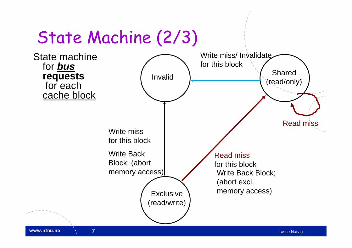
State Machine (2/3)State machine
for busrequestsfor each cache block
Invalid Shared(read/only)
Exclusive(read/write)
Write BackBlock; (abortmemory access)
Write miss for this block
Read miss for this block
Write miss/ Invalidatefor this block
Write Back Block; (abort excl.memory access)
Read miss

8 Lasse Natvig
State Machine (3/3)• State machine
for CPU requestsfor each cache block andfor bus requestsfor each cache block
Place read misson bus
InvalidShared
(read/only)
Exclusive(read/write)
CPU Read miss
CPU Write
CPU Read hit
Place Write Miss on bus
CPU read missWrite back block,Place read misson bus
CPU WriteMiss => Write Miss on BusHit => Invalidate on Bus
CPU Read missPlace read miss on bus
CPU Write Miss, Write back cache block, Place write miss on bus
CPU read hitCPU write hit
Write miss/Invfor this block
Write BackBlock; (abort excl.memory access)
Write missfor this block
Read miss for this block
Write BackBlock; (abortmemory access)

9 Lasse Natvig
State Machine, case (a)
• Address conflict miss; The cache block stores dirty data, but for another memory address than what is requested (different tags).
• Replacement action. Must write back dirty data.• Write miss on buss will be seen by memory that will send the requested block• (We cannot just update the block locally after the write-back, since we write one
word that is only a part of the entire block --- we must read in the entire block, then update one word in that block, and the new block is set to state exclusive) (If block size = word-size we could omit the “Place write miss on bus”)
InvalidShared
(read/only)
Exclusive(read/write)
CPU Write Miss, Write back cache block, Place write miss on bus
State machinefor CPUrequestsfor each cache block

10 Lasse Natvig
State Machine, case (b)State machine
for busrequestsfor each cache block
Invalid Shared(read/only)
Exclusive(read/write)
Read miss• someone else is requesting this block, and they
will get a sharer-copy from memory or from a cache with the block in state shared (and clean)

11 Lasse Natvig
SYNCHRONIZATION ---BIG PICTURE P
M
P
M
P
M
Network

12 Lasse Natvig
Synchronization• Central concept for all kinds of parallelism
– Synchronize access to shared resources– Order events from cooperating processes correctly– Used for all standard shared memory programming
• In smaller multiprocessor systems– Implemented by uninterrupted instruction(s) atomically accessing
a value– Requires special hardware support– Simplifies construction of OS / parallel applications

13 Lasse Natvig
• Swaps value in register for value in memory– Mem = 0 means not locked, Mem = 1 means locked– How does this work
• Register <= 1 ; Processor want to lock• Exchange(Register, Mem)
– If Register = 0 Success• Mem was = 0 Was unlocked• Mem is now = 1 Now locked
– If Register = 1 Fail• Mem was = 1 Was locked• Mem is now = 1 Still locked
• Exchange must be atomic!
Atomic exchange (swap)

14 Lasse Natvig
• One alternative: Load Linked (LL) and Store Conditional (SC)– Used in sequence; (1) LL (2) SC
• If memory location accessed by LL changes, SC fails• If context switch between LL and SC, SC fails
– Implemented using a special link register• Contains address used in LL• Reset (to zero) if matching cache block is invalidated or if
we get an interrupt• SC checks if link register contains the same address. If
so, we have atomic execution of LL & SC
Implementing atomic exchange (1/2)

15 Lasse Natvig
• Example code to implement EXCH (R4, 0(R1)):try: MOV R3, R4 ; mov exchange value
LL R2, 0(R1) ; load linkedSC R3, 0(R1) ; store conditionalBEQZ R3, try ; branch if SC failedMOV R4, R2 ; put load value in R4
• This can now be used to implement e.g. spin locksDADDUI R2, R0, #1 ; R0 always = 0
lockit: EXCH R2, 0(R1) ; atomic exchangeBNEZ R2, lockit ; already locked?// R2 = 0, «we got the lock and are inside»
Implementing atomic exchange (2/2)
16 Lasse Natvig
APPENDIX F INTERCONNECTION NETWORKS
Available under Its’ learning

17 Lasse Natvig
Introduction/”Big picture”

18 Lasse Natvig
• Basic network technology assumed known• Motivation
– Increased importance• System-to-system connections• Intra system connections
– Increased demands• Bandwidth, latency, reliability, energy efficiency, ...
– Vital part of system design
Motivation

19 Lasse Natvig
Types of networks
Number of devices and distance
• OCN – On-chip network▫ Functional units, register files, caches,
…▫ Cores in a multicore▫ Also known as: Network on Chip
(NoC)
• SAN – System/storage area network▫ Multiprocessor and multicomputer,
storage
• LAN – Local area network• WAN – Wide area network
• Trend: Switches replace buses

20 Lasse Natvig
F.2: Connecting two devicesDestination implicit

21 Lasse Natvig
Software to Send and Receive• SW Send steps
1: Application copies data to OS buffer2: OS calculates checksum, starts timer3: OS sends data to network interface HW and says start
• SW Receive steps3: OS copies data from network interface HW to OS buffer2: OS calculates checksum, if matches send ACK; if not,
deletes message (sender resends when timer expires)1: If OK, OS copies data to user address space and
signals application to continue• Sequence of steps for SW: protocol

22 Lasse Natvig
22
OCNs SANs LANs WANs
Med
ia t
ype
Distance (meters)0.01 1 10 100 >1,000
Basic Network Structure and Functions• Media and Form Factor
Fiber Optics
Coaxialcables
Myrinetconnectors
Cat5E twisted pair
Metal layers
Printedcircuitboards
InfiniBandconnectors
Ethernet

23 Lasse Natvig
Packet latency
Sender
Receiver
SenderOverhead
Transmission time(size/bandwidth)
Transmission time(size/bandwidth)
Time ofFlight
ReceiverOverhead
Transport Latency
Total Latency = Sender Overhead + Time of Flight + Message Size / bandwidth + Receiver Overhead
Total Latency
(processorbusy)
(processorbusy)

24 Lasse Natvig
F.3: Connecting multiple devices (1/3)• New issues
– Topology• What paths are possible for
packets?– Routing
• Which of the possible paths are allowable (valid) for packets?
– Arbitration• When are paths available for
packets?– Switching
• How are paths allocated to packets?

25 Lasse Natvig
Connecting multiple devices (2/3)
• Two types of topology– Shared media– Switched media
• Shared media (bus)– Arbitration
• Carrier Sensing• Collision Detection
– Routing is simple• Only one possible path

26 Lasse Natvig
Connecting multiple devices (3/3)• Switched media▫ “Point-to-point” connections between
active switch components▫ Routing for each packet
▫ Through a series of hops▫ Arbitration for each connection
• Comparison▫ Much higher aggregate BW in switched
network than shared media network▫ Shared media is cheaper▫ Distributed arbitration simpler for
switched

27 Lasse Natvig
• One switch or bus can connect a limited number of devices– Complexity, cost, technology, …
• Interconnected switches needed for larger networks• Topology: connection structure
– What paths are possible for packets?– All pairs of devices must have path(s) available
• A network is partitioned by a set of links if their removal disconnects the graph– Bisection bandwidth– Important for performance
F.4: Interconnection Topologies

28 Lasse Natvig
• Common topology for connecting CPUs and I/O units
• Also used for interconnecting CPUs
• Fast and expensive (O(N2))
• Non-blocking
Crossbar
P
P
C
C
I/O
I/O
M MM M

29 Lasse Natvig
000001
010011
100101
110111
000001
010011
100101
110111
0
1
0
1
1
1
Source Destination
2x2 switches
Straight Crossover
Upper broadcast Lower broadcast
Omega network
• Example of multistage network. Combine multiple 2x2 crossbars
• Usually log2n stages for n inputs - O(N log N)• Can block

30 Lasse Natvig
Linear Arrays and Rings
• Linear Array– Diameter = N - 1– Bisection bandwidth = bandwidth of one link– Route A B given by relative address R = B-A
• Ring (= 1D torus (torus is normally 2D))
Linear Array
Ring (torus)
Ring (torus) arranged to use short wires
Figure F.13

31 Lasse Natvig
Linear Arrays and Rings
• Linear array = 1D grid• 2D grid• Torus has wrap-around
connections• CRAY with 3D torus Switch
P$
External I/O
Memctrl
and NI
Mem
• Distributed switched networks
•

32 Lasse Natvig
Trees
• Diameter and average distance are logarithmic▫ k-ary tree, height d = logk N▫ address = d-vector of radix k coordinates describing path down
from root
• Fixed number of connections per node (i.e. fixed degree)
• Bisection bandwidth = 1 near the root

33 Lasse Natvig
Fat-Trees
• Fatter links (really more of them) as you go up, so bisection bandwith scales with N
Fat Tree
Example: CM-5 Thinned Fat Tree

34 Lasse Natvig
Hypercubes• Also called binary n-cubes. # of nodes = N = 2n
• O(logN) hops• Good bisection bandwidth• Out degree is n = logN• Scaling of machine requires
higher degree in allnodes (switches)– impractical– 2D and 3D mesh
more popular
0-D 1-D 2-D 3-D 4-D
5-D

35 Lasse Natvig
F.5: Routing, Arbitration, Switching• Routing
– Which of the possible paths are allowable for packets?– Set of operations needed to compute a valid path
• Arbitration– When are paths available for packets?– Resolves packets requesting the same resources at the same time – For every arbitration, there is a winner and possibly many losers
• Losers are buffered (lossless) or dropped on overflow (lossy)
• Switching– How are paths allocated to packets?– The winning packet (from arbitration) proceeds towards destination – Paths can be established one fragment at a time or in their entirety

36 Lasse Natvig
Routing• Shared Media▫ Broadcast to everyone
• Switched Media needs real routing. Options:▫ Source-based routing: message specifies path to the destination
(changes of direction)▫ Virtual Circuit: circuit established from source to destination,
message picks the circuit to follow▫ Destination-based routing: message specifies destination, switch
must pick the path Deterministic: always follow same path Adaptive: pick different paths to avoid congestion, failures Randomized routing: pick between several good paths to balance
network load

37 Lasse Natvig
Store & Forward vs Cut-Through Routing
23 1 0
23 1 0
23 1 0
23 1 0
23 1 0
23 1 0
23 1 0
23 1 0
23 1 0
23 1 0
23 1 0
23 1
023
3 1 0
2 1 0
23 1 0
0
1
2
3
23 1 0Time
Store & Forward Routing Cut-Through Routing
Source Dest Dest

38 Lasse Natvig
Routing mechanism• Need to select output port for each input packet▫ And fast…
• Simple arithmetic in regular topologies▫ Example: x, y routing in a grid with bi-directional links
(first x then y) west (-x) x < 0 east (+x) x > 0 south (-y) x = 0, y < 0 north (+y) x = 0, y > 0
• Unidirectional links sufficient for torus (+x, +y)• Dimension-order routing (DOR)▫ Reduce relative address of each dimension in order to avoid
deadlock

39 Lasse Natvig
Deadlock• How can it arise?▫ necessary conditions: shared resources incrementally allocated non-preemptible
How do you handle it?▫ constrain how channel
resources are allocated(deadlock avoidance)
▫ Add a mechanism thatdetects likely deadlocks and fixes them(deadlock recovery)

40 Lasse Natvig
Deadlock – example 1 Red: S1 d1Green:S2 d2Blue: S3 d3Black: S4 d4

41 Lasse Natvig
Deadlock example 1, avoided by Dimension Order Routing (DOR)

42 Lasse Natvig
Deadlock example 2
• Deadlock can occur even with DOR if uni-directional links– Can be solved by having two (virtual) channels
TRC (0,0) TRC (0,1) TRC (0,2) TRC (0,3)
TRC (1,0) TRC (1,1) TRC (1,2) TRC (1,3)
TRC (2,0) TRC (2,1) TRC (2,2) TRC (2,3)
TRC (3,0) TRC (3,1) TRC (3,2) TRC (3,3)
XX

43 Lasse Natvig
Arbitration (1/2)• Several simultaneous
requests to shared resource
• Ideal: Maximize usage of network resources
• Problem: Starvation– Fairness needed
• Figure: Two phase arbitration.– Request, Grant– Poor usage (two
unused units, due to too few requests)

44 Lasse Natvig
Arbitration (2/2)
• Three phases• Multiple
requests from one sender
• Better usage• But:
Increased latency

45 Lasse Natvig
• Allocating paths for packets• Two techniques:
– Circuit switching (connection oriented)• Communication channel• Allocated before first packet• Packet headers don’t need routing info• Wastes bandwidth
– Packet switching (connection less)• Each packet handled independently• Can’t guarantee response time• Two types – next slide
Switching
46 Lasse Natvig
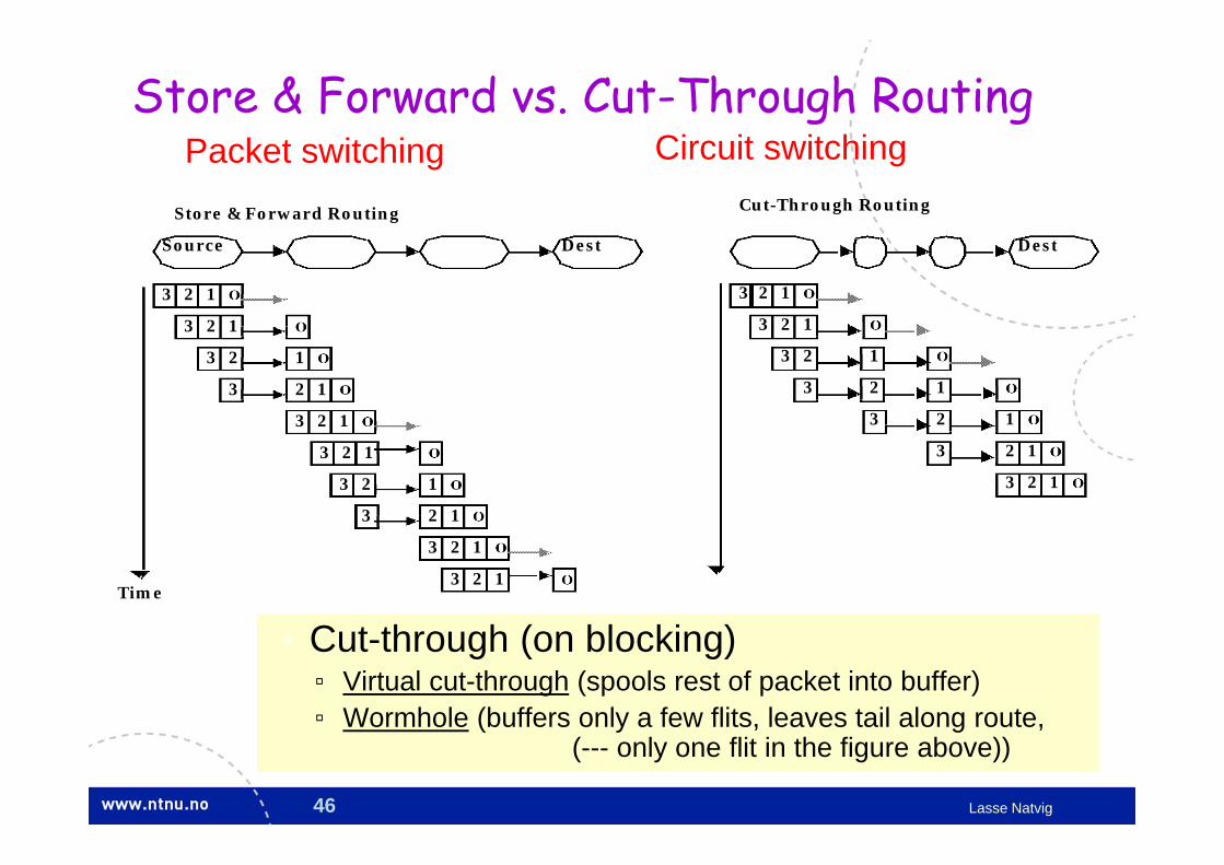
Store & Forward vs. Cut-Through Routing
• Cut-through (on blocking)▫ Virtual cut-through (spools rest of packet into buffer)▫ Wormhole (buffers only a few flits, leaves tail along route,
(--- only one flit in the figure above))
23 1 0
23 1 0
23 1 0
23 1 0
23 1 0
23 1 0
23 1 0
23 1 0
23 1 0
23 1 0
23 1 0
23 1
023
3 1 0
2 1 0
23 1 0
0
1
2
3
23 1 0Time
Store & Forward Routing Cut-Through Routing
Source Dest Dest
Packet switching Circuit switching

47 Lasse Natvig
Switch micro architecture

48 Lasse Natvig
Pipe
lined
swi
tch

49 Lasse Natvig
DATAFLOW COMPUTING AND MDM

50 Lasse Natvig
Dataflow computing and computers
• Dataflow computing– suitable for highly parallel solutions – requires different HW and SW
• Dataflow computers– Principles– History– Statical vs. dynamical – Typical architecture
• pipelined ring with circulating packets
• Manchester Dataflow Machine (MDM)

51 Lasse Natvig
Dataflow programs
• Represent computation as a graph• Node = operation = instruction• Computation flows through• Inherently parallel, data driven, no
program counter, asynchronous• Logical processor at each node,
activated by availability of operands, executed when a physical processor is available
1 b
a
+
c e
d
f
Dataflow graphf = a x d
a = (b +1) x (b - c)
d = c x e

52 Lasse Natvig
Example — data flow

53 Lasse Natvig
Control flow and data flow• (Traditional) control-flow
– Explicit control flow (manipulation of program counter (PC))– Data are communicated between instructions via shared memory
locations – Data is referenced via memory-address– One single control thread – Many parallel control threads:
• Explicit parallelism
• Data flow computers – Data driven computation, that is the selection of instructions for
execution is controlled by the availability of operands• Implicit parallelism
– Programs represented as directed graphs– Results are sent directly as data-packets between instructions– Has normally/originally no shared memory that more than one
instruction may refer to • i.e. no side effects