TDM PWs Yaakov (J) Stein Chief Scientist RAD Data Communications.
49
TDM PWs TDM PWs Yaakov (J) Stein Chief Scientist RAD Data Communications
-
Upload
everett-atkinson -
Category
Documents
-
view
220 -
download
1
Transcript of TDM PWs Yaakov (J) Stein Chief Scientist RAD Data Communications.

TDM PWsTDM PWs
Yaakov (J) Stein Chief ScientistRAD Data Communications
TDMoIP Slide 2
OutlineOutline
1) Pseudowires
2) Emulating TDM
3) TDMoIP encapsulation formats
4) TDM signaling transport
5) Timing recovery
6) Packet loss and mis-ordering
TDMoIP Slide 3
PseudowiresPseudowires
Pseudowire (PW): Pseudowire (PW): A mechanism that emulates the A mechanism that emulates the essential attributes of a native service while transporting essential attributes of a native service while transporting over a packet switched network (PSN)over a packet switched network (PSN)

TDMoIP Slide 4
The The oldold model model (X.200, OSI)(X.200, OSI)
Once upon a time networks were exclusively described by the OSI
model
However
few networks actually work only that way
highly inflexible (always need more layers!)
some features only in one place (security, mux)
missing features (OAM)
doesn’t help to design transport networks PHYSICAL
LINK
NETWORK
TRANSPORT
SESSION
PRESENTATION
APPLICATION

TDMoIP Slide 5
Simple telephony counter-exampleSimple telephony counter-example
this type of scenario important to carriers, and thus to ITU-T
not captured by ISO layering model
there can be an arbitrary large number of intervening layers
all intermediate layers fulfill the same function -- transport
voice channel
E1 (TDM)
E3 (PDH)
STM1 (SDH)
OC3 (OTN)
voice channel
E1 (TDM)
E3 (PDH)
STM1 (SDH)
OC3 (OTN)OSI physical layer
OSI application layer
?
TDMoIP Slide 6
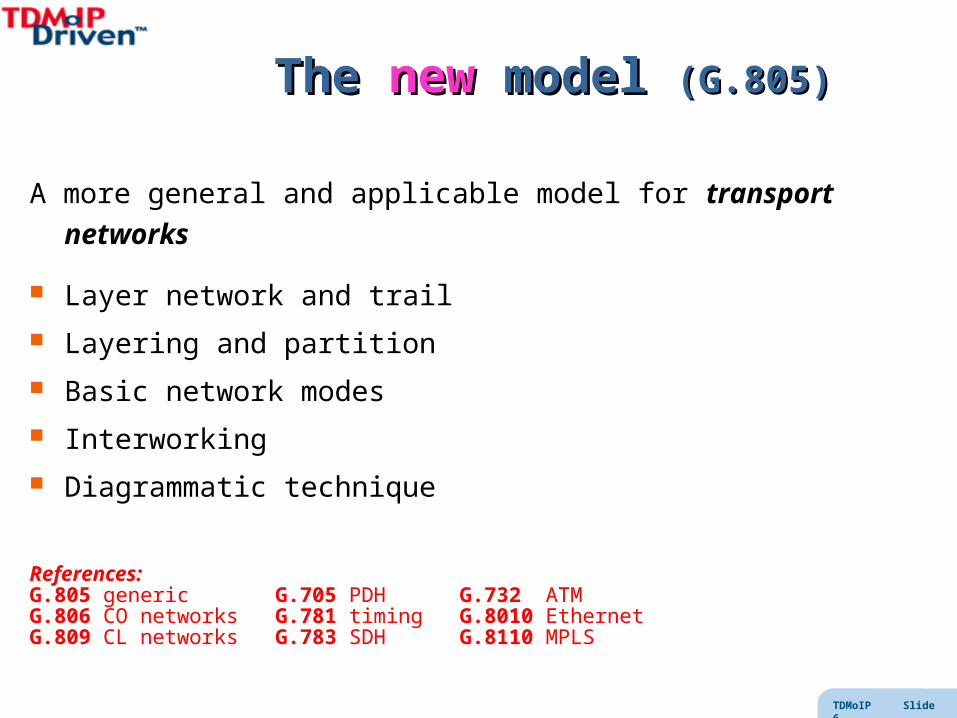
The The newnew model model (G.805)(G.805)
A more general and applicable model for transport networks
Layer network and trail
Layering and partition
Basic network modes
Interworking
Diagrammatic technique
References:G.805 generic G.705 PDH G.732 ATMG.806 CO networks G.781 timing G.8010 Ethernet G.809 CL networks G.783 SDH G.8110 MPLS

TDMoIP Slide 7
Layer networksLayer networks
LayeringNetwork may be decomposed (vertically) into layer networksClient-server relationship between adjacent layer networks
Layer networkBasic topological component for information transferLink in layer network supported by network belowLayer network provides link connection to layer aboveLayers are completely independent
Trail Transport entity in layer network Contains client payload and OAM
PartitioningNetwork may be decomposed (horizontally) into subnetworks connected by linksRecursively, each subnetwork is similarly decomposedPeer-peer relationship between adjacent subnetworks

TDMoIP Slide 8
Network ModesNetwork Modes
Many native network types (technologies) for each mode– CS: TDM, PDH, SDH, OTN– CO: ATM, FR, MPLS, TCP/IP, SCTP/IP– CL: UDP/IP, IPX, Ethernet, CLNP
Can layer any mode over any mode – BUT some layerings may involve performance loss– CL over CO over CS is EASY– CO over CL, or CS over CO is harder– CS over CL is very hard
Circuit Switched
(CS)
Packet Switched
(PSN)
Connection Oriented
(CO)
Connectionless
(CL)

TDMoIP Slide 9
Network interworking (tunneling)Network interworking (tunneling)Network interworking may be provided by tunneling (edge to edge)
Service Interworking requires more complex mechanisms
networkNativeService
NativeService
edge edge
NativeService
A
NativeService
B
network
TDMoIP Slide 10
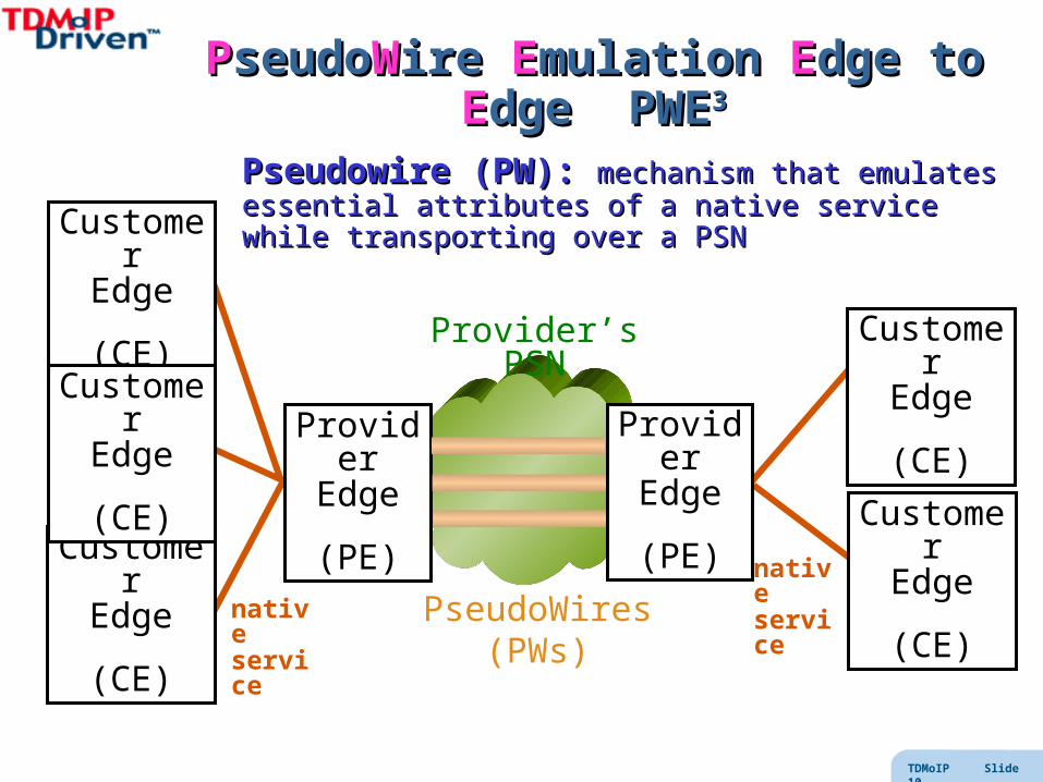
PPseudoseudoWWire ire EEmulation mulation EEdge to dge to EEdge dge PWEPWE33
ProviderEdge
(PE)Customer
Edge
(CE)
CustomerEdge
(CE)
CustomerEdge
(CE)
nativeservice
Provider’s PSN
PseudoWires (PWs)
CustomerEdge
(CE)
CustomerEdge
(CE)
ProviderEdge
(PE)nativeservice
Pseudowire (PW): Pseudowire (PW): mechanism that emulates essential mechanism that emulates essential attributes of a native service while transporting over a PSNattributes of a native service while transporting over a PSN

TDMoIP Slide 11
Emulating TDMEmulating TDM
From PSTN to PSNFrom PSTN to PSN

TDMoIP Slide 12
Classic TelephonyClassic Telephony
Circuit switched ensures signal integrity Very High Reliability (“five nines”) Low Delay and no noticeable echo Timing information transported over the network Mature Signaling Protocols (over 3000 features)
T1/E1
COSWITCH
analog lines
SONET/SDHNETWORK
PBX
extensions
Access Network
T1/E1 or AAL1/2
PBX
Core (Backbone) Network
SynchronousNon-packet network
COSWITCH
TDMoIP Slide 13
A few G.XXX sayings …A few G.XXX sayings …
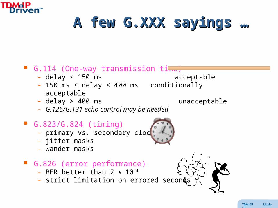
G.114 (One-way transmission time)– delay < 150 ms acceptable– 150 ms < delay < 400 ms conditionally acceptable– delay > 400 ms unacceptable– G.126/G.131 echo control may be needed
G.823/G.824 (timing)– primary vs. secondary clocks– jitter masks– wander masks
G.826 (error performance)– BER better than 2 * 10-4
– strict limitation on errored seconds

TDMoIP Slide 14
TDM PWsTDM PWs
TDMoIP replaces CS core with a PSNThe access networks and their protocols remain !TDM PseudowireCan G.xxx compliance be maintained?
T1/E1/T3/E3
analog lines
PBX
extensions
Access Network
PBX
T1/E1 or AAL1/2
Packet Switched Network
Asynchronous networkNo timing information transfer

TDMoIP Slide 15
Network ComparisonNetwork Comparison
TDM
Circuit switched
Guaranteed BW
Low overhead
Minimal delay
Constant arrival rate
Timing transport
No information loss
PSN
Connection oriented / connectionless
Shared BW
High overhead
Delay (introduced by forwarding)
Packet delay variation (and bursts)
No physical layer clock
Packet loss (congestion, errors)

TDMoIP Slide 16
TDMoIP Protocol ProcessingTDMoIP Protocol Processing
Steps in TDMoIP The synchronous bit stream is segmented The TDM segments are adapted TDMoIP control word is prepended PSN (IP/MPLS) headers are prepended (encapsulation) Packets are transported over PSN to destination PSN headers are utilized and stripped Control word is checked, utilized and stripped TDM stream is reconstituted (using adaptation) and played out
TDMframes
TDMframes
IP Packets
PSN
IP Packets
TDMoIP Slide 17
TDMoIP vs. VoIPTDMoIP vs. VoIP
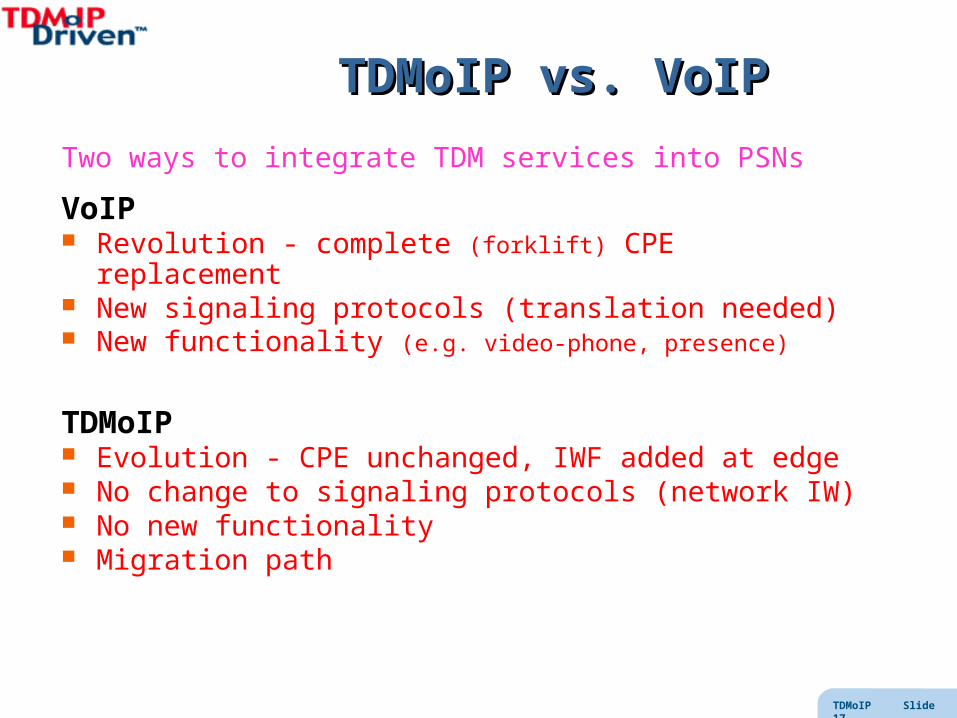
Two ways to integrate TDM services into PSNs
VoIP Revolution - complete (forklift) CPE replacement New signaling protocols (translation needed) New functionality (e.g. video-phone, presence)
TDMoIP Evolution - CPE unchanged, IWF added at edge No change to signaling protocols (network IW) No new functionality Migration path

TDMoIP Slide 18
TDMoIP encapsulation formatsTDMoIP encapsulation formats
TDMoIP Slide 19
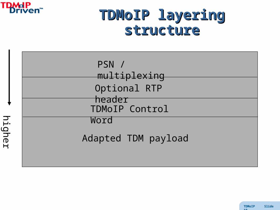
TDMoIP layering structureTDMoIP layering structure
PSN / multiplexing
Optional RTP header
TDMoIP Control Word higher layers
Adapted TDM payload

TDMoIP Slide 20
PW MultiplexingPW Multiplexing
to reduce resources in core networkPWs are sent inside PSN tunnels
we often wish to send several PWs in same tunnel
to demux we use a PW label
for application muxing, IANA has assigned to TDMoIP
UDP port number 0x085E (2142)
in IP networks we use UDP source port number as bundle ID
in MPLS networks we use an inner label
for L2TPv3 we could use L2TP multiplexing
TDMoIP Slide 21
Packet ComponentsPacket Components
PSN headers• ensure packet transported to destination
RTP header• contains timestamp that may help in timing recovery
Control Word • enables detection of out-of-order and lost packets• indicates critical alarm conditions
TDM payload may be adapted• to assist in timing recovery and recovery from packet loss• to ensure proper transfer of TDM signaling• to provide an efficiency vs. latency trade-off
TDMoIP Slide 22
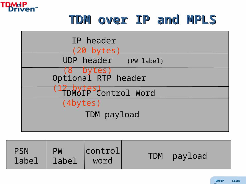
TDM over IP and MPLSTDM over IP and MPLS
IP header (20 bytes)
UDP header (PW label) (8 bytes)
Optional RTP header (12 bytes)
TDMoIP Control Word (4bytes)
TDM payload
PSN label
PW label
controlword
TDM payload

TDMoIP Slide 23
TDMoIP Control WordTDMoIP Control Word
PID (4b) special uses
flags (4 b)– L bit (Local failure)– R bit (Remote failure)
FRG (2 bits) indicates fragmentation (only for special uses)
Length (6 b) used when packet may be padded
Sequence Number (16 b) used to detect packet loss / misordering
PID flags FRG Length Sequence Number

TDMoIP Slide 24
TDM PayloadTDM Payload
What needs to be transported from end to end? Voice (telephony quality, low delay, echo-less) Tones (for dialing, PIN, etc.) Fax and modem transmissions Signaling (there are 1000s of PSTN features!) Timing
T1/E1frame
SYNC TS1 TS2 TS3signaling
bits… … TSn
(1 byte)
“timeslots”

TDMoIP Slide 25
Why not N bytes?Why not N bytes?
Why don’t we simply encapsulate N bytes frame?
IP N TDM octetsUDP RTP?
because a single lost packet would cause service interruption need constant N (else don’t know how many TDM bytes were lost) need to conceal lost packet by proper amount of AIS “all ones” TDM synchronization would be lost
SAToP is good for well-engineered networks essentially no packet loss very low PDV (see below)

TDMoIP Slide 26
Why not one frame?Why not one frame?
Why don’t we simply encapsulate the T1/E1 frame?
IP T1/E1 frame
24 or 32 bytes
UDP RTP?
because it is inefficient - however N frames is reasonable (structure-locking)
because a single lost packet could cause service interruption and for CAS, signaling uses a superframe (16/24 frames) so superframe integrity must be respected too
because we want to efficiently handle fractional T1/E1
because we want a latency vs. efficiency trade-off
TDMoIP Slide 27
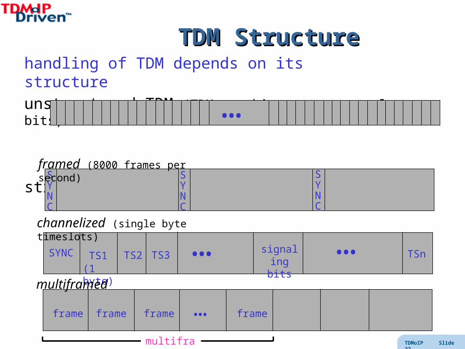
TDM StructureTDM Structurehandling of TDM depends on its structure
unstructured TDM (TDM = arbitrary stream of bits)
structured TDM
…
SYNC TS1 TS2 TS3signaling
bits… … TSn
(1 byte)
channelized (single byte timeslots)
SYNC
framed (8000 frames per second)SYNC
SYNC
multiframed
frame frame frame … frame
multiframe

TDMoIP Slide 28
TDM transport typesTDM transport types
Structure-agnostic transport (SAToP)• for unstructured TDM• even if there is structure, we ignore it• simplest way of making payload• OK if network is well-engineered
Structure-aware transport (TDMoIP, CESoPSN)• take TDM structure into account• must decide which level of structure (frame, multiframe, …)• can overcome PSN impairments (PDV, packet loss, etc)
TDMoIP Slide 29
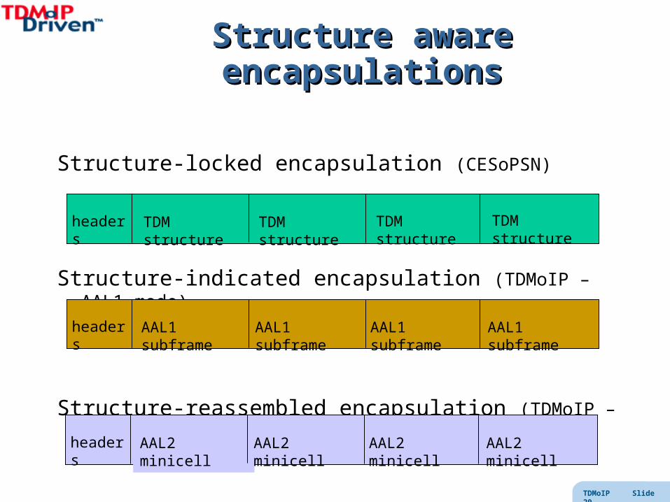
Structure aware encapsulationsStructure aware encapsulations
Structure-locked encapsulation (CESoPSN)
Structure-indicated encapsulation (TDMoIP – AAL1 mode)
Structure-reassembled encapsulation (TDMoIP – AAL2 mode)
headers TDM structure TDM structure TDM structureTDM structure
headers AAL1 subframe AAL1 subframe AAL1 subframe AAL1 subframe
headers AAL2 minicell AAL2 minicell AAL2 minicell AAL2 minicell

TDMoIP Slide 30
Structure indication - AAL1Structure indication - AAL1
For robust emulation: adding a packet sequence number adding a pointer to the next superframe boundary only sending timeslots in use allowing multiple frames per packet
for example
UDP/IP T1/E1 frames (only timeslots in use)seqnum(with CRC)
ptr
TS1 TS2 TS5 TS7 TS1 TS2 TS5 TS77 @
TDMoIP Slide 31
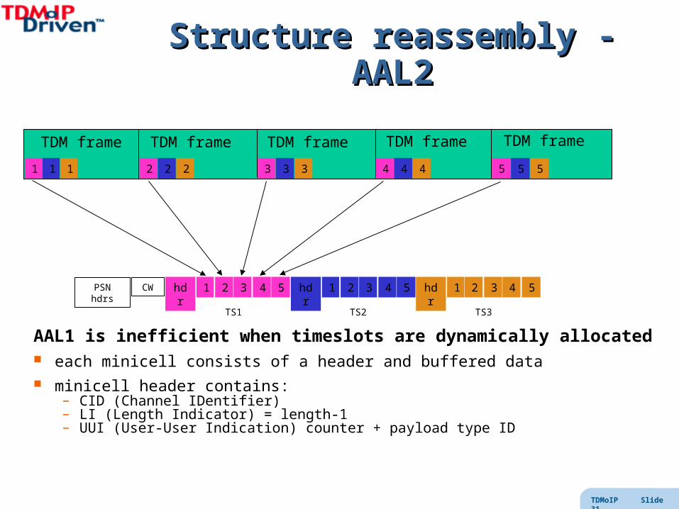
Structure reassembly - AAL2Structure reassembly - AAL2
AAL1 is inefficient when timeslots are dynamically allocated each minicell consists of a header and buffered data minicell header contains:
– CID (Channel IDentifier)– LI (Length Indicator) = length-1– UUI (User-User Indication) counter + payload type ID
TDM frame TDM frame TDM frameTDM frameTDM frame
1 2 4 531 1 2 2 3 3 4 4 5 5
1 2 3 4 5hdr 1 2 3 4 5hdr 1 2 3 4 5hdrPSN hdrs CW
TS1 TS2 TS3

TDMoIP Slide 32
TDM SignalingTDM Signaling

TDMoIP Slide 33
Signaling?Signaling?
signaling is used for network control – call setup/tear-down (including routing)– OAM– billing
in TDM networks there may be different types:– Subscriber - CO – CO - CO– CO - CPE (e.g. PBX)
there are four common PSTN signaling techniques:– Analog * (E&M, ground-start/loop-start, ring-voltage, etc)– In-band (dial-tone, ring-back, DTMF,etc)– CAS – Channel Associated Signaling– CCS – Common Channel Signaling
* we needn’t discuss the analog techniques
TDMoIP Slide 34
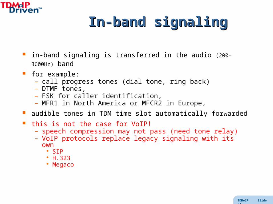
In-band signalingIn-band signaling
in-band signaling is transferred in the audio (200-3600Hz) band for example:
– call progress tones (dial tone, ring back)– DTMF tones, – FSK for caller identification, – MFR1 in North America or MFCR2 in Europe,
audible tones in TDM time slot automatically forwarded this is not the case for VoIP!
– speech compression may not pass (need tone relay)– VoIP protocols replace legacy signaling with its own
SIP H.323 Megaco
TDMoIP Slide 35
CASCAS
CAS is carried in the same T1/E1 as payload – but not in the audio – T1 uses robbed bits – E1 uses a dedicated time slot (usually TS16)
Readily handled by TDMoIP (even for fractional T1/E1 links)
VoIP systems need to – detect the CAS bits, – interpret them according to the appropriate protocol – transport them through PSN using a relay protocol – finally regenerate and recombine them at the far end

TDMoIP Slide 36
CCSCCS
Examples: ISDN PRI signaling, SS7
if occupy a TDM timeslot (trunk associated)then forwarded by TDMoIP (see HDLCoIP)
if not trunk associated, then forwarded by signaling networkor signaling gateway employed
encapsulate (relay) the native signaling forward as additional traffic through the PSN

TDMoIP Slide 37
HDLCoIPHDLCoIPHDLCoIP intended to operate in port mode
Data / control messages transparently transported
Assume messages shorter than the MTU (no fragmentation)
Only use when has potential to significantly compress BW
Transmission :– monitor flags until frame detected– test FCS– if incorrect - discarded– if correct -
perform unstuffing flags and FCS removed send frame
TDMoIP Slide 38
TDM Timing RecoveryTDM Timing Recovery

TDMoIP Slide 39
TDM Jitter and WanderTDM Jitter and Wander
Jitter = short term timing variation *(i.e. fast jumps - frequency > 10 Hz)
Jitter amplitude in UIpp
Unit Interval pk-pk
E1 : 1 UIpp = 1/2MHz = 488 ns
Wander = long term timing variation *(i.e. slow moving- frequency < 10 Hz)
Measure in MTIE() or TDEV()MTIE - max pk-pk errorTDEV expected deviation
Mask as function of
* compared to reference clock
Note: requirements for E1 given in G.823 for T1 given in G.824

TDMoIP Slide 40
PSN - Delay and PDVPSN - Delay and PDV
PSNs do not carry timing clock recovery required for TDMoIP
PSNs introduce delay and packet delay variation (PDV) Delay degrades perceived voice quality PDV makes clock recovery difficult
PSN
The arrival time is not constant!!!
E1/T1 VOICE
DATA
E1/T1 VOICE
DATA
TDMoIP
GW
TDMoIP
GW

TDMoIP Slide 41
Jitter BufferJitter Buffer
Arriving TDMoIP packets written into jitter buffer
Once buffer filled 1/2 can start reading from buffer
Packets read from jitter buffer at constant rateHow do we know the right rate?How do we guard against buffer overflow/underflow?
PSN
E1/T1 VOICE
DATA
E1/T1 VOICE
DATA
Jitter Buffer
TDMoIP
GWTDMoIP
GW

TDMoIP Slide 42
Clock RecoveryClock Recovery
The packets are injected into network ingress at times Tn
For TDM the source packet rate R is constant
Tn = n / R
The network delay Dn can be considered to be the sum of
typical delay d and random delay variation Vn
The packets are received at network egress at times tn
tn = Tn + Dn = Tn + d + Vn
By proper averaging/filtering
tn = Tn + d = n / R + d
and the packet rate R has been recovered

TDMoIP Slide 44
FLLFLLWe can estimate the rate R
by counting the number of arrivals N per unit time Tthe longer the averaging the better the estimate
R = N / TOpen loop frequency settingBetter method is closed loop
Measure reception rate Fn = 1 / (tn - tn-1)
Correct present rate F according to filtered Fn
F = F + < Fn - F >
TDMoIP
GW
F
n

TDMoIP Slide 45
PLLPLLPhase difference between
write (arrival) clock and read (present local) clock
Number of packets written into the jitter buffer
minus the number of packets read from the jitter buffer
write events
read events
360o
270o
counter

TDMoIP Slide 46
Packet Loss and MisorderingPacket Loss and Misordering
TDMoIP Slide 47
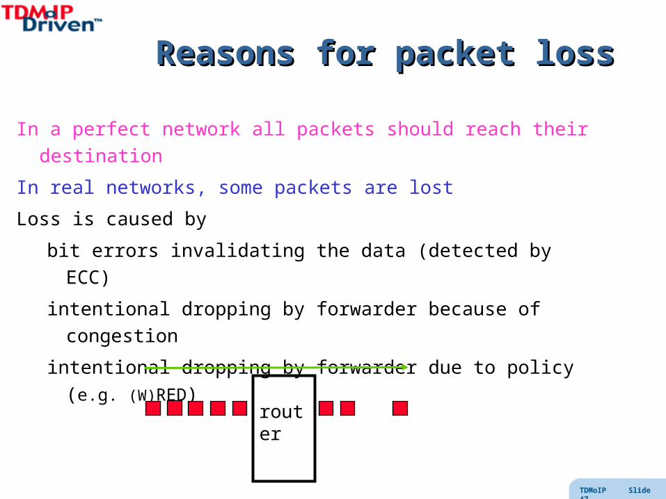
Reasons for packet lossReasons for packet loss
In a perfect network all packets should reach their destination
In real networks, some packets are lost
Loss is caused by
bit errors invalidating the data (detected by ECC)
intentional dropping by forwarder because of congestion
intentional dropping by forwarder due to policy (e.g. (W)RED)
router
TDMoIP Slide 48
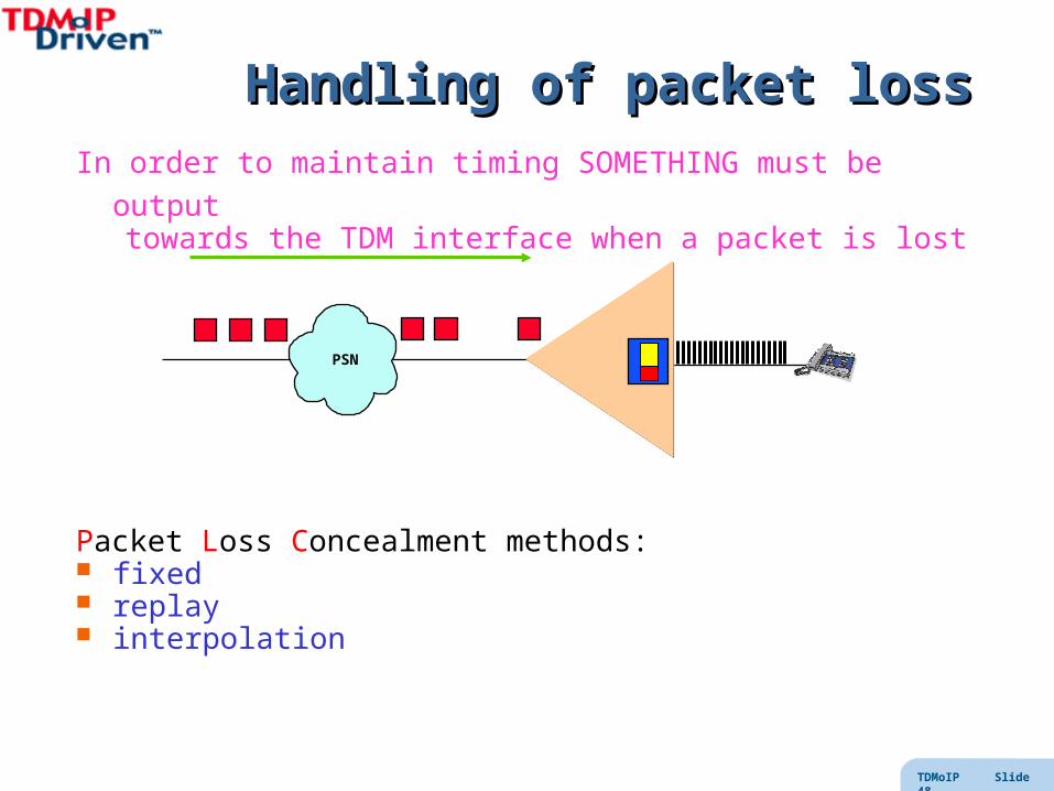
Handling of packet lossHandling of packet loss
In order to maintain timing SOMETHING must be outputtowards the TDM interface when a packet is lost
Packet Loss Concealment methods: fixed replay interpolation
PSN

TDMoIP Slide 49
Voice Quality ComparisonVoice Quality Comparison
See draft-stein-pwe3-tdm-packetloss-00.txt

TDMoIP Slide 50
Mis-orderingMis-ordering
In a perfect network all packets should arrive in proper order
In real networks, some packets are delayed (or even duplicated!)
Misordering is caused by parallel paths– aggravated by load balancing mechanisms
Misordering can be handled by Reordering (from jitter buffer) Handling as packet loss and dropping later
router router1 2 3 4 5 1 2 4 3 5
1 2
3
4
5


![[Yaakov Kraftmakher] Experiments and Demonstr](https://static.fdocuments.in/doc/165x107/55cf9df9550346d033b01791/yaakov-kraftmakher-experiments-and-demonstr.jpg)