TDK RF Products Training Module for Digikey - Mouser Electronics · TDK RF Products Training Module...
19
RF Product Marketing TDK RF Products Training Module for Mouser Jan, 2011
Transcript of TDK RF Products Training Module for Digikey - Mouser Electronics · TDK RF Products Training Module...

RF Product Marketing
TDK RF Products
Training Module for Mouser
Jan, 2011
RF Product Marketing
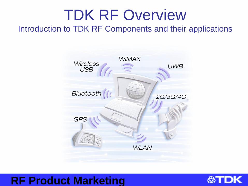
TDK RF OverviewIntroduction to TDK RF Components and their applications

RF Product Marketing
What is a BPF/LPF/Diplexer/Coupler/Balun?
BPF
-80
-70
-60
-50
-40
-30
-20
-10
0
1000 1500 2000 2500 3000 3500 4000 4500 5000
Frequency(M H z)
Attenuatio
n
Frequency band
A device that passes frequencies within
A certain range and rejects (attenuates)
un-wanted signals.
LPF
S21
-80
-70
-60
-50
-40
-30
-20
-10
0
1000 1500 2000 2500 3000 3500 4000 4500 5000
Frequency(M H z)
Attenuation
Frequency band
A device that allows signals below a
designated frequency to pass and
rejects the un-desired upper frequency
signals.
Coupler
PACoupler
A device that is used to monitor a signal
Without interrupting the signal.
Diplexer
S21
-80
-70
-60
-50
-40
-30
-20
-10
0
1000 1500 2000 2500 3000 3500 4000 4500 5000
Frequency(M H z)
Attenuation
A device that Routes two different
frequencies from a common port
(example: One antenna port can route
2.4GHz and 5GHz signals)
BalunBalun
A device that converts between Balanced
to Unbalanced electrical signals.

RF Product Marketing
What is a BPF?• A Band Pass Filter allows a desired frequency range to pass through
while attenuating (rejecting) unwanted frequencies. For example a
desired Cellular or WLAN frequency can be allowed to pass while
rejecting other unwanted radio frequencies.
-80
-70
-60
-50
-40
-30
-20
-10
0
1 1.4 1.8 2.2 2.6 3
Frequency[GHz]
Ga
in[d
B] Attenuation
(Highband)
Attenuation
(Lowband)
Pass band
Reference characteristics
BPF
Operation Principal
A BPF circuit consists of Inductors and
capacitors built into Dielectric ceramic
creating a resonance frequency. This
resonance frequency provides
attenuation at certain frequencies.
RF Product Marketing
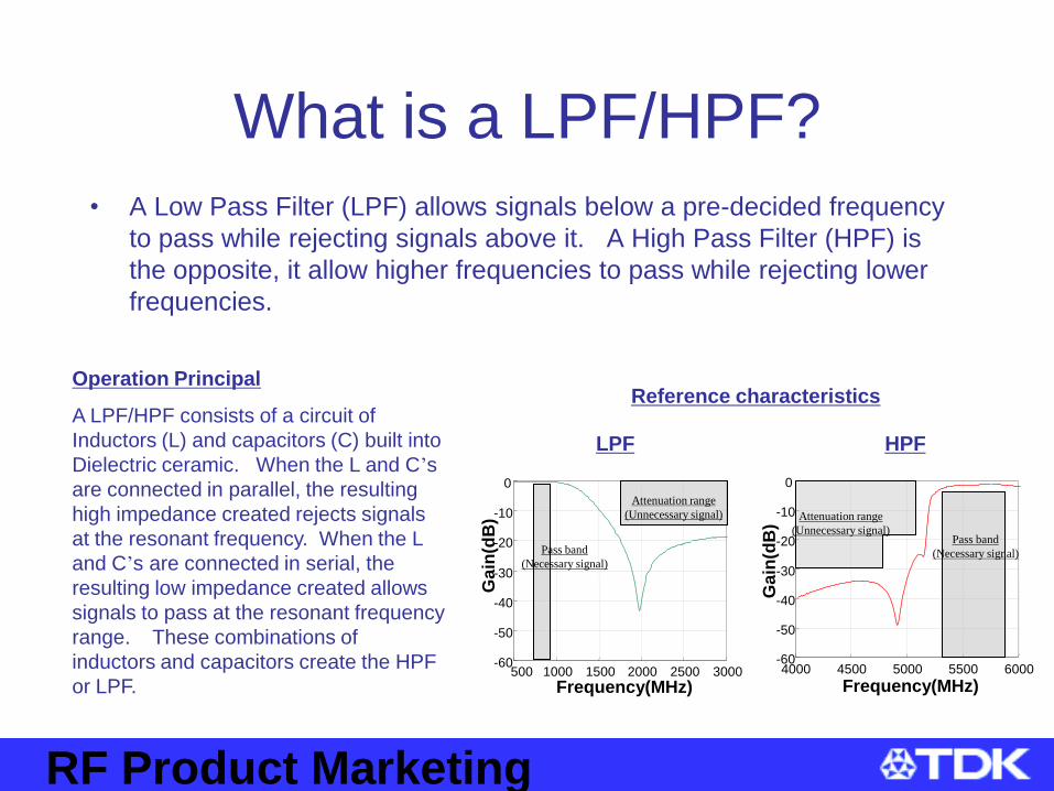
What is a LPF/HPF?
• A Low Pass Filter (LPF) allows signals below a pre-decided frequency
to pass while rejecting signals above it. A High Pass Filter (HPF) is
the opposite, it allow higher frequencies to pass while rejecting lower
frequencies.
-60
-50
-40
-30
-20
-10
0
500 1000 1500 2000 2500 3000
Frequency(MHz)
Ga
in(d
B)
Pass band
(Necessary signal)
Attenuation range
(Unnecessary signal)
0
-10
-20
-30
-40
-50
-604000 4500 5000 5500 6000
Frequency(MHz)
Ga
in(d
B)
Pass band
(Necessary signal)
Attenuation range
(Unnecessary signal)
Reference characteristics
LPF HPF
Operation Principal
A LPF/HPF consists of a circuit of
Inductors (L) and capacitors (C) built into
Dielectric ceramic. When the L and C’s
are connected in parallel, the resulting
high impedance created rejects signals
at the resonant frequency. When the L
and C’s are connected in serial, the
resulting low impedance created allows
signals to pass at the resonant frequency
range. These combinations of
inductors and capacitors create the HPF
or LPF.

RF Product Marketing
What is a Diplexer?• Diplexers are 3-port filters that divide two frequencies from a common
port. A Typical application is a diplexer for WLAN, this diplexer
receives the WLAN signal from the antenna port and directs the signal
to either the High band (5GHz) or the Low band (2.4GHz).
COMMON
(Antenna)
High Band Low Band
LPF
(BPF)HPF
(BPF)
-50-45-40
-35
-30
-25-20
-15
-10-5
0
400 800 1200 1600 2000 2400
Frequency[MHz]
Ga
in[d
B]
Lowband (824-960MHz)
-50-45-40-35-30-25-20-15-10-50
400 800 1200 1600 2000 2400
Frequency[MHz]
Ga
in[d
B]
Highband(1710-1990MHz)
Operation Principal
A diplexer is a combination of a LPF or BPF
at the low band and a HPF or BPF at the high
band.
Basic conceptReference characteristics
Low band
High band

RF Product Marketing
What is a Balun?• A balun transformer converts an unbalanced signal into a balanced
signal or a balanced signal into an unbalanced signal. A balun can
also provide an impedance matching function. In a WLAN system a
balun is used on the transmit signal path between the RF-IC (Balanced
signal) and the Power Amplifier (Unbalanced signal). The balun
performs as a balanced to unbalanced signal transformer and an
Impedance matching transformer.
Equivalent Circuit
4 Quarter Wave-length
Resonators
BALANCED OUTPUT
UNBALANCED
INPUT
Electric field
maximum
Magnetic coupling maximum
Current maximum
Electric field
maximum
An induced current
+ -
An induced current
Operation Principal
A balun circuit is created by coupling two
pairs of λ/4 resonators each with a unique
operating frequency wavelength. A balanced
signal is produced by coupling resonators of
equal size and its phase reversed 180
degrees. The impedance is adjusted by a
combination of the pattern width and distance
within the balun.

RF Product Marketing
What is a Coupler?• Also known as a Directional Coupler. This device is used to monitor
information on a signal (Ex. Frequency, power level) without
interrupting the main system power path. In a WLAN system a coupler
is sometimes used to monitor the output signal and control the PA
output.
Main currentIN OUT
L1
L2
C1 C2
MONITOR
M
LOAD
(50ohm)
L2
weakenstrengthen
Operation Principal
Basically, a coupler function has a combination of two
inductor and capacitors existing in near proximity that the
power is coupled from one signal line to another.
Tx
Directional
CouplerPA
Detection, AGC Circuit
INOUT
MONITOR LOAD
(50ohm)
(Pick up a part of PA) (Feedback to PA)
Equivalent Circuit The example of practical use

RF Product Marketing
What is an antenna?• An Antenna is a component used for receiving or transmitting Electro-
magnetic waves. An antenna converts an electrical current into an
electron-magnetic wave or vice versa. An antenna radiates an
electromagnetic field (wave) in response to applying a voltage and
current. Each wavelength has a specific frequency and wavelength
(the length of an electric wave). The wavelength is inverse proportion
to the value of frequency. The size of an antenna is based on this
wavelength. Usually an antenna is a ½ or ¼ wavelength.
Antenna Radiation Patterns

RF Product Marketing
RF Components for Wireless Local Area Network (WLAN)
• What is 802.11a/b/g/n
– 802.11a/b/g/n refer to the WLAN standards created by the IEEE (Institue of Electrical and Electronics Engineers, Inc.). These WLAN standards are used to create interoperable WLAN products.
– The original WLAN products were 802.11b followed by 802.11a.
– The most popular WLAN products today are 802.11g which use the same frequency (2.4GHz) and are backward compatible to 802.11b products.
– 802.11n is the next proposed standard. This uses a Multiple Input/Multiple Output (MIMO) technology. 802.11n products can work in either 2.4GHz or 5GHz
– TDK has components for use in 2.4GHz and 5GHz WLAN systems
Protocol Release Date Op. Freq. Data Rate Range (Indoor)Range (Outdoor)
*include one wall
802.11a 1999 5GHz 54Mbit/s - 35 meters - 120 meters
802.11b 1999 2.4GHz 11Mbit/s -38 meters -140 meters
802.11g 2003 2.4GHz 54Mbit/s -38 meters -140 meters
802.11n 20092.4GHz
5GHz248Mbit/s -70 meters -250 meters

RF Product Marketing
RF Components for WLAN• Block Diagram (IEEE802.11a/b/g Dual Band)
Diplexer
2.4GHz
ANT
PA
RF IC
5 GHz
Diplexer
ANT
Rx Path
Tx Path
ANT
for WLAN
SW
PA
LNA
BalunBPF
BalunBPF
BalunBPF
BalunBPF
Balanced BPF
Balanced BPF
Balanced BPF
Balanced BPF
5 GHz
2.4GHz
ExampleLNA
RF Product Marketing
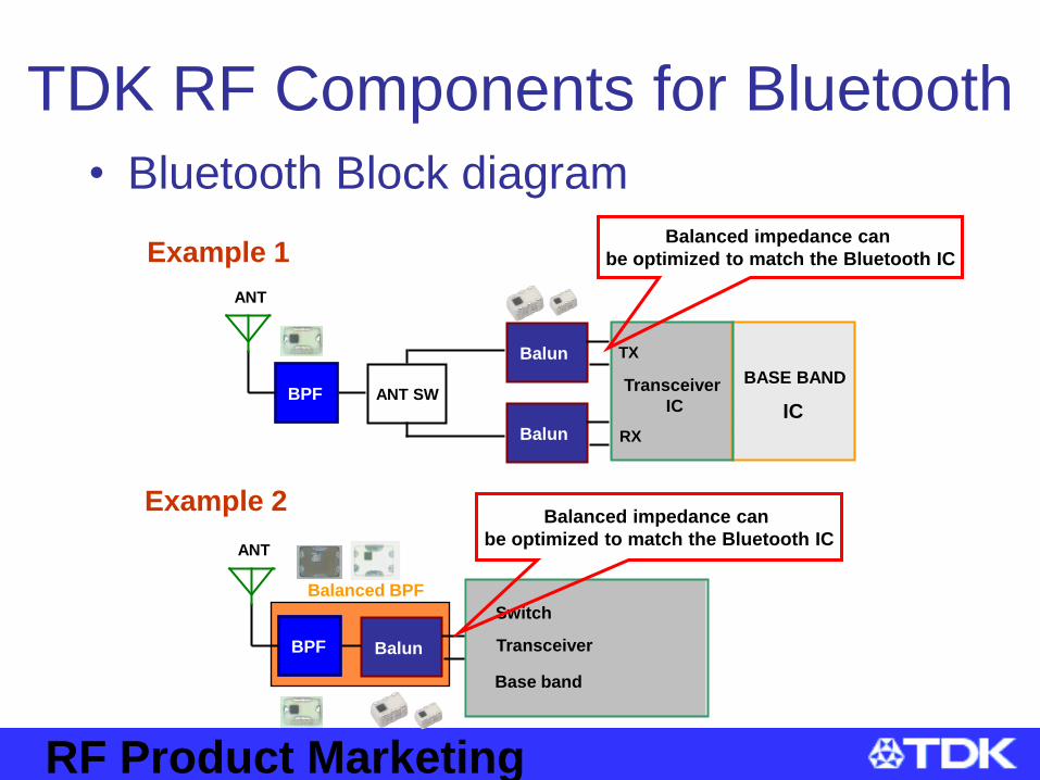
TDK RF Components for Bluetooth
• Bluetooth Block diagram
BASE BAND
IC
TX
RX
Transceiver
ICANT SWBPF
ANT
Balun
Balun
Example 2
BPF
ANT
Base band
Balun
Switch
Transceiver
Balanced BPF
Example 1
Balanced impedance can
be optimized to match the Bluetooth IC
Balanced impedance can
be optimized to match the Bluetooth IC

RF Product Marketing
TDK RF Components for WiMAX• WiMAX Block diagram (Dualband)
Diplexer
Rx BPF
Rx BPF
Balun
Balun
Diplexer
Tx BPF
Tx BPF
PA
PA
Tx BPF
Tx BPF
Balun
Balun
RF-IC
3.5G Rx
2.5G Rx
3.5G Tx
2.5G Tx
LNA
LNA
Balanced BPF
Balanced BPF
Example
Receive
Transmit
RF Product Marketing
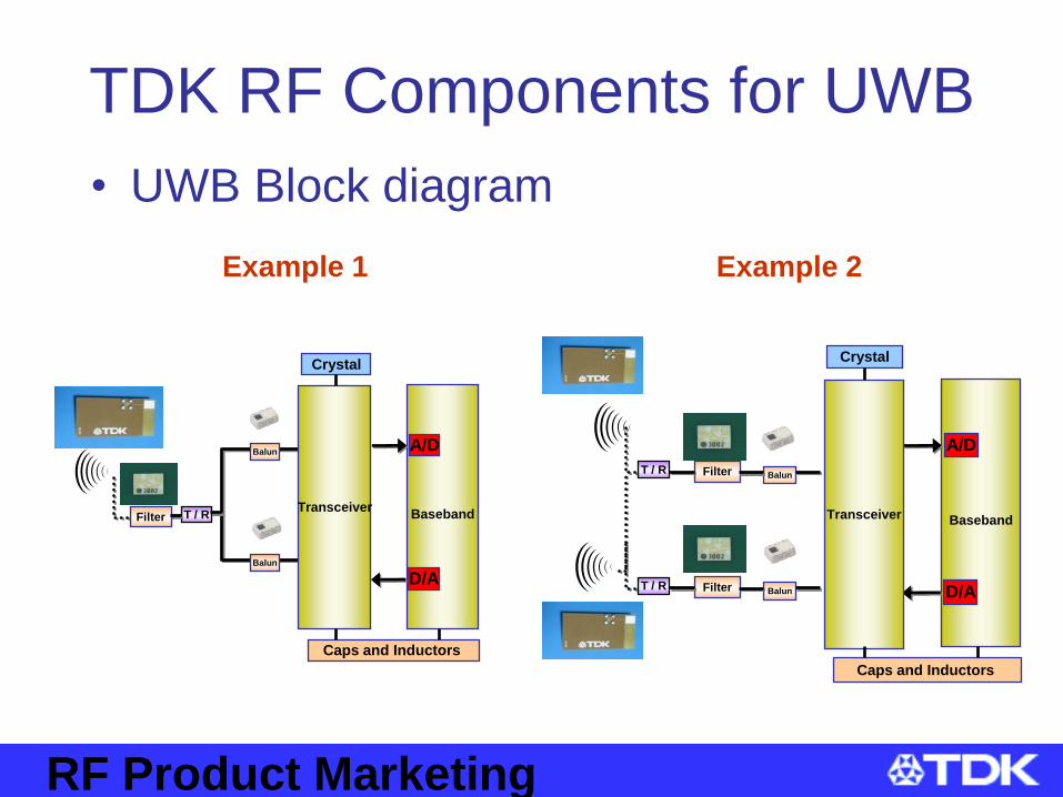
TDK RF Components for UWB
• UWB Block diagram
Baseband
A/D
D/A
TransceiverT / RFilter
Balun
Balun
Caps and Inductors
Crystal
Baseband
A/D
D/A
Transceiver
T / R Filter Balun
Caps and Inductors
Crystal
T / R Filter Balun
Example 2Example 1

RF Product Marketing
TDK RF Components
RF Product Marketing
TDK RF Overview• Why is TDK manufacturing RF components?
– TDK has been instrumental in the development of
RF technologies for over 15 years. TDK RF
components use the same Low Temperature Co-
fired Ceramic (LTCC) technology used in our
ceramic capacitors and inductors. TDK RF
components are designed to meet critical real-
world applications from leading RF IC
manufacturers.

RF Product Marketing
Why Use TDK Components ?
• Miniature Size– As Wireless systems continue to be used in more
and more applications, the need for smaller RF components increases. TDK’s continuous materials development allows us to design smaller RF components without sacrificing performance and quality.
• TDK RF components are developed for specific IC’s & applications– TDK works with Industry leading RF IC
manufacturers to create RF components for use in WLAN, WiMAX, Bluetooth and UWB systems.

RF Product Marketing
TDK R&D Corporation
Phoenix, USA
TDK RF Solutions
Austin, USA
TDK Corporation
Tokyo, Japan
TDK Electronics Ireland
Dublin, Ireland
TDK Maintains RF Design centers in Japan, Ireland and the US. These
design centers are located close to our customers and partners to
provide direct and close communications.
Global Presence : World-Wide Technical Support

RF Product Marketing
Summary• TDK RF Components are designed for use in
various wireless technologies. TDK products provide the performance, size and cost targets to meet your RF product requirements. For more information please contact:
• Contacts
• TDK Website Links– http://www.tdk.co.jp/tefe02/rf_network.htm
• Links to Mouser’s TDK Parts List