TD-700 Laboratory Fluorometer - Turner Designs Laboratory Fluorometer Operating Manual Page 1 TD-700...
55
TD-700 Laboratory Fluorometer Operating Manual TD-700 Laboratory Fluorometer Operating Manual Dated: 5/8/2002 Version 2.0 Part Number 7000-998
Transcript of TD-700 Laboratory Fluorometer - Turner Designs Laboratory Fluorometer Operating Manual Page 1 TD-700...
TD-700 Laboratory Fluorometer Operating Manual
Page 1
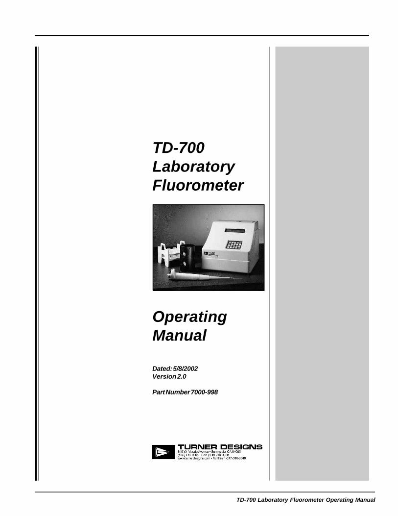
TD-700LaboratoryFluorometer
OperatingManual
Dated: 5/8/2002Version 2.0
Part Number 7000-998

TD-700 Laboratory Fluorometer Operating Manual
Page 1
TD-700LaboratoryFluorometer
OperatingManual
Dated: 5/8/2002Version 2.0
Part Number 7000-998

TD-700 Laboratory Fluorometer Operating Manual
Page 2
TD-700 Laboratory FluorometerOperating Manual
Table of Contents
I. Introduction 5A. DescriptionB. Inspection and SetupC. General PrecautionsD. Definition of Symbols
II. Hardware Overview 7A. TD-700 Quick View DiagramB. TD-700 Controls
III. Optical Filter Installation and Removal 9
IV. Lamp Installation and Removal 11A. The Mercury Vapor LampB. The Quartz Halogen Lamp
V. Instrument Parameters (Firmware) 13A. Power-up ScreenB. HOME ScreenC. Setup/Calibration ScreenD. Setup ScreensE. Calibration ScreensF. Firmware Flow Chart
VI. Calibration Overview 18A. Why Calibrate?B. When to CalibrateC. TD-700 Calibration Options
VII. Calibration: Simple Mode 20
VIII. Calibration: Multi-Optional Mode - Raw Fluorescence 22
IX. Calibration: Multi-Optional Mode - Direct Concentration 24A. To CalibrateB. How Sample Concentrations Will Be CalculatedC. To View the Last CalibrationD. To Abort the Calibration
X. Reading Samples 28A. Reading SamplesB. Resetting Blank to ZeroC. Data Stream
TD-700 Laboratory Fluorometer Operating Manual
Page 3
APPENDICES
APPENDIX 1 - Before Calibration or Reading Samples 30A. Materials NeededB. When Handling SamplesC. Linear Range and "Quenching"
Figure 1: Linearity, Calibration Curve, and QuenchingD. Temperature ConsiderationsE. Positioning SamplesF. Data Quality
APPENDIX 2 - The Calibration Printout 33
A. Printout Capability with a Printer or ComputerB. Sample Reading with a Printer or ComputerC. Calibration Printout Using the Direct Concentration Calibration
ProcedureD. Calibration Printout in the Multi-Optional Raw Fluorescence CalibrationE. Calibration Printout Using the Simple Mode
APPENDIX 3 - Alarms & Diagnostics 36A. Alarm ScreenB. Diagnostic Screens
APPENDIX 4 - Troubleshooting 38
APPENDIX 5 - Data Collection 39
APPENDIX 6 - Sample and Cuvette Adapters 40A. Installing and Removing Sample AdaptersB. Minicell Adapter
APPENDIX 7 - Glossary 42
APPENDIX 8 - Error Messages and Notes 45A. Invalid InputB. Error1C. Notes 1 and 2D. Error3E. Error4F. Error5G. Error6H. Home Screen Displays: OVER, or Negative (-) NumbersI. Blank Level Error
APPENDIX 9 - Maintenance, Warranty, & Service 47A. MaintenanceB. WarrantyC. Obtaining Service
APPENDIX 10 - Specifications & Features 49
APPENDIX 11 - Principles of Fluorescence 51
APPENDIX 12 - Instructions for Using the Solid Standard 53
TD-700 Laboratory Fluorometer Operating Manual
Page 4
NOTES

TD-700 Laboratory Fluorometer Operating Manual
Page 5
I. Introduction
A. Description
The TD-700 Fluorometer is a compact, laboratory fluorometer designed fordiscrete sample measurement of various fluorescent materials, includingchlorophyll, rhodamine, fluorescein, histamine, vitamins, and other fluores-cent compounds. When properly calibrated, TD-700 will electronically setthe optimal sensitivity and range for your samples, and will readout theactual concentration of the compound when in the Direct Concentrationmode. The TD-700 can be set up to detect the specific compound youwant to measure simply by changing the lamp and optical filters.
B. Inspection and Setup
Upon receiving your fluorometer, please inspect it carefully and make sureall accessories are present (refer to the packing list shipped with theinstrument).
To get started (Refer to the Quick View Diagram, page 7):
1. Locate the instrument on a flat surface with the back of the instrumentwell ventilated (at least three inches from a wall).
2. Open the sample chamber lid located on the top of the unit.
3. Remove the Filter Cylinder by grasping the inside rim of the cylinderand pulling up.
4. Install the correct optical filters for your application. See Section III fordetails.
5. Check that the correct lamp is installed for your primary application.See Section IV for details.
6. Check to see that the sample adaptor is the correct one for yourneeds. Refer to Appendix 6 for a detailed explanation of TD-700Sample Adaptors.
7. Reinsert the Filter Cylinder, lining up either the A, B, C or D applica-tion indicators on the cylinder with the silver alignment mark on theinside rim of the sample chamber. Replace the sample adaptor makingsure that the adaptor is properly seated in the filter cylinder, and closethe sample chamber lid.
8. Plug in the unit. Be sure to use only the Turner Designs powersupply provided with your instrument. It is critical to use the powersupply provided by Turner Designs to meet EMI requirements.
9. Turn on the power switch (rear of unit) and allow the unit to warm up forthe countdown period (600 seconds; 10 minutes).
NOTE: For optimal instrument stability, leave the instrument turned on.
TD-700 Front View
TD-700 Side View
Filter CylinderAssembly
TD-700 Top View

TD-700 Laboratory Fluorometer Operating Manual
Page 6
C. General Precautions
Do not leave the instrument reading "OVER" for an extended period of time(several minutes). Instrument instability can result.
If you are using the quartz halogen lamp, do not touch the bulb. It may behot. Also, oils from your hand will affect the lamp's transmission.
When using solvents or other chemicals, please refer to the appropriateMaterial Safety Data Sheet (MSDS) for information regarding handling.
When using potentially hazardous chemicals, please use closed-cap testtubes whenever possible and limit exposure. If closed cap test tubes arenot available, Parafilm™ should be used to prevent the spillage of volatile orother potentially hazardous chemicals.
Chemicals should be used in accordance with local regulations and usedin a well ventilated area.
Do not defeat the lamp interlock switch. UV light may cause permanentdamage to your eyes.
D. Definition of Symbols
Direct Current. 12 volts D.C.
Easily touched higher temperature parts.
Caution. Read instruction manual and refer to warning text.
TD-700 Laboratory Fluorometer Operating Manual
Page 7
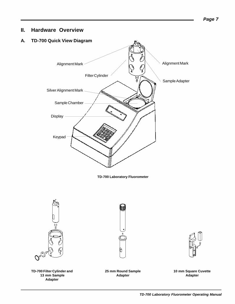
TD-700 Laboratory Fluorometer
TD-700 Filter Cylinder and 13 mm Sample
Adapter
25 mm Round SampleAdapter
10 mm Square CuvetteAdapter
II. Hardware Overview
A. TD-700 Quick View Diagram
Alignment Mark Alignment Mark
Sample AdapterFilter Cylinder
Silver Alignment Mark
Sample Chamber
Display
Keypad
TD-700 Laboratory Fluorometer Operating Manual
Page 8
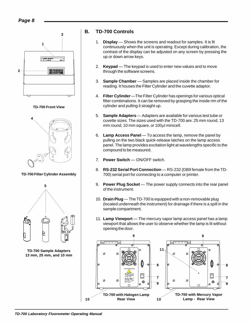
TD-700 Front View
4
TD-700 Filter Cylinder Assembly
5
TD-700 Sample Adapters13 mm, 25 mm, and 10 mm
6
8
7
9
TD-700 with Halogen LampRear View10
TD-700 with Mercury VaporLamp - Rear View10
B. TD-700 Controls
1. Display — Shows the screens and readout for samples. It is litcontinuously when the unit is operating. Except during calibration, thecontrast of the display can be adjusted on any screen by pressing theup or down arrow keys.
2. Keypad — The keypad is used to enter new values and to movethrough the software screens.
3. Sample Chamber — Samples are placed inside the chamber forreading. It houses the Filter Cylinder and the cuvette adaptor.
4. Filter Cylinder —The Filter Cylinder has openings for various opticalfilter combinations. It can be removed by grasping the inside rim of thecylinder and pulling it straight up.
5. Sample Adapters — Adapters are available for various test tube orcuvette sizes. The sizes used with the TD-700 are: 25 mm round, 13mm round, 10 mm square, or 100µl minicell.
6. Lamp Access Panel — To access the lamp, remove the panel bypulling on the two black quick-release latches on the lamp accesspanel. The lamp provides excitation light at wavelengths specific to thecompound to be measured.
7. Power Switch — ON/OFF switch.
8. RS-232 Serial Port Connection — RS-232 (DB9 female from the TD-700) serial port for connecting to a computer or printer.
9. Power Plug Socket — The power supply connects into the rear panelof the instrument.
10. Drain Plug — The TD-700 is equipped with a non-removable plug(located underneath the instrument) for drainage if there is a spill in thesample compartment.
11. Lamp Viewport — The mercury vapor lamp access panel has a lampviewport that allows the user to observe whether the lamp is lit withoutopening the door.
3
1
2
6
8
7
9
11
TD-700 Laboratory Fluorometer Operating Manual
Page 9
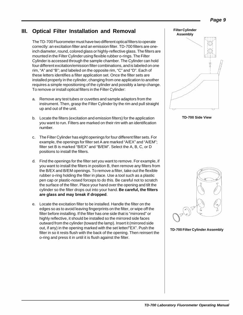
TD-700 Side View
TD-700 Filter Cylinder Assembly
Filter CylinderAssembly
III. Optical Filter Installation and Removal
The TD-700 Fluorometer must have two different optical filters to operatecorrectly: an excitation filter and an emission filter. TD-700 filters are one-inch diameter, round, colored glass or highly-reflective glass. The filters aremounted in the Filter Cylinder using flexible rubber o-rings. The FilterCylinder is accessed through the sample chamber. The Cylinder can holdfour different excitation/emission filter combinations, and is labeled on onerim, “A” and “B”; and labeled on the opposite rim, “C” and “D”. Each ofthese letters identifies a filter application set. Once the filter sets areinstalled properly in the cylinder, changing from one application to anotherrequires a simple repositioning of the cylinder and possibly a lamp change.To remove or install optical filters in the Filter Cylinder:
a. Remove any test tubes or cuvettes and sample adaptors from theinstrument. Then, grasp the Filter Cylinder by the rim and pull straightup and out of the unit.
b. Locate the filters (excitation and emission filters) for the applicationyou want to run. Filters are marked on their rim with an identificationnumber.
c. The Filter Cylinder has eight openings for four different filter sets. Forexample, the openings for filter set A are marked “A/EX” and “A/EM”;filter set B is marked “B/EX” and “B/EM”. Select the A, B, C, or Dpositions to install the filters.
d. Find the openings for the filter set you want to remove. For example, ifyou want to install the filters in position B, then remove any filters fromthe B/EX and B/EM openings. To remove a filter, take out the flexiblerubber o-ring holding the filter in place. Use a tool such as a plasticpen cap or plastic-nosed forceps to do this. Be careful not to scratchthe surface of the filter. Place your hand over the opening and tilt thecylinder so the filter drops out into your hand. Be careful, the filtersare glass and may break if dropped.
e. Locate the excitation filter to be installed. Handle the filter on theedges so as to avoid leaving fingerprints on the filter, or wipe off thefilter before installing. If the filter has one side that is “mirrored” orhighly reflective, it should be installed so the mirrored side facesoutward from the cylinder (toward the lamp). Insert it (mirrored sideout, if any) in the opening marked with the set letter/”EX”. Push thefilter in so it rests flush with the back of the opening. Then reinsert theo-ring and press it in until it is flush against the filter.

TD-700 Laboratory Fluorometer Operating Manual
Page 10
f. Locate the emission filter to be installed. Handle the filter at the edgesso as to avoid leaving fingerprints on the filter, or wipe off the filterbefore installing. If the filter has one side that is “mirrored” or highlyreflective, it should be installed so the mirrored side faces toward theinside of the cylinder (toward the sample). Insert it (mirrored side in, ifany) in the opening marked with the appropriate set letter/”EM”. Pushthe filter in so it rests flush with the back of the opening. Then reinsertthe o-ring and press in with your plastic pen cap until it is flush againstthe filter.
g. Position the Filter Cylinder in the sample chamber so that the align-ment mark for the filter set you are using is aligned with the silveralignment mark on the inside rim of the sample chamber.

TD-700 Laboratory Fluorometer Operating Manual
Page 11
IV. Lamp Installation and Removal
There are two types of lamps available for the TD-700: the Mercury Vaporand the Quartz Halogen
A. The Mercury Vapor Lamp
The low pressure mercury vapor lamp comes in various types dependingon the application of interest. The average life of a mercury vapor lamp is8000 hours. The lamp can be checked without removing the lamp accesspanel by viewing through the lamp view port. If the lamp access panel isremoved, the power to the mercury lamp will be cut off. This safety featurewill prevent the user from being exposed to U.V. light. Do not defeat theinterlock switch. U.V. light may cause permanent damage to youreyes.
Check the lamp view port if:
1. The instrument is not responding, even though the unit is plugged inand the power is on.
2. The readings are very low, unstable, or drifting.
Note: After replacing a lamp, you must always recalibrate.
To replace the mercury vapor lamp:
1. Unplug the instrument and remove the lamp access panel by pullingon the two black quick-release latches on the rear panel of the instru-ment.
2. Before replacing a lamp, make sure the current lamp is fully seated inboth the upper and lower lamp sockets. Be cautious when remov-ing the lamp. It may be hot.
3. To remove the lamp, grasp it carefully and turn it about 90 degreesuntil the prongs line up with the slots on the lamp sockets. Slide it out.
NOTE: To avoid breaking the lamp when replacing it, make sure it isfully seated! At the bottom lamp socket, a metal spring exerts pres-sure against the lamp; be sure this spring is not preventing properseating before twisting lamp into place.
4. To install a new lamp, line up the lamp prongs with the slots on thelamp sockets, push the lamp in and turn it about 90 degrees so it isfirmly seated. Make sure both end caps are properly seated or thelamp will not work!
5. Replace the lamp access panel and push in the black quick-releaselatches to snap the panel in place.
6. Turn on the power. Check the lamp view port to ensure the lamp is lit.Also make sure the fan is operating. If the fan is not operating, checkthe connector plug.
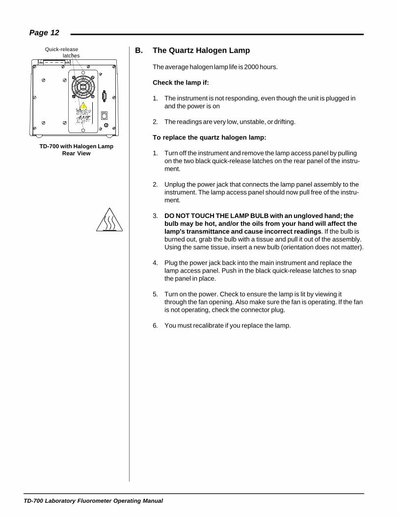
Quick-releaselatches
Lamp View Port
TD-700 with Mercury VaporLamp - Rear View
TD-700 Laboratory Fluorometer Operating Manual
Page 12
TD-700 with Halogen LampRear View
Quick-releaselatches
B. The Quartz Halogen Lamp
The average halogen lamp life is 2000 hours.
Check the lamp if:
1. The instrument is not responding, even though the unit is plugged inand the power is on
2. The readings are very low, unstable, or drifting.
To replace the quartz halogen lamp:
1. Turn off the instrument and remove the lamp access panel by pullingon the two black quick-release latches on the rear panel of the instru-ment.
2. Unplug the power jack that connects the lamp panel assembly to theinstrument. The lamp access panel should now pull free of the instru-ment.
3. DO NOT TOUCH THE LAMP BULB with an ungloved hand; thebulb may be hot, and/or the oils from your hand will affect thelamp's transmittance and cause incorrect readings. If the bulb isburned out, grab the bulb with a tissue and pull it out of the assembly.Using the same tissue, insert a new bulb (orientation does not matter).
4. Plug the power jack back into the main instrument and replace thelamp access panel. Push in the black quick-release latches to snapthe panel in place.
5. Turn on the power. Check to ensure the lamp is lit by viewing itthrough the fan opening. Also make sure the fan is operating. If the fanis not operating, check the connector plug.
6. You must recalibrate if you replace the lamp.

TD-700 Laboratory Fluorometer Operating Manual
Page 13
C. Setup/Calibration Screen
1. Setup2. Calibration
XXX ppm<ENT> -Setup & Cal
B. HOME Screen
TURNER DESIGNST7-1B 10/96 600
A. Power-up Screen
V. Instrument Parameters (Firmware)
Instrument parameters are set through the TD-700 firmware interface.Firmware screens are called up using the keypad. To see how thescreensfit together, see the firmware flowchart on pages 16 & 17. For details aboutalarms and instrument diagnostics, see Appendix 3, Section A, andSection B.
A. Power-up Screen
When the unit is first turned on, a screen appears showing the title,software version, and a 600-second (10-minute) countdown. Once the 600-second countdown expires, the HOME screen will appear. The countdownallows the instrument to warm up adequately before measurements begin.For optimal stability and accuracy, it is recommended that you allow theinstrument to complete the countdown period. For best results, leave theinstrument turned on in your laboratory.
If you wish to bypass the countdown period, press <H>, <ESC>, or<ENT>. From the HOME screen, press <9> to return to the Power-upscreen.
B. HOME Screen
After the countdown period, the HOME screen is displayed. The HOMEscreen is where samples are read and data is sent to the printer orcomputer. Press <H> to return to this screen from any screen (exceptduring calibration).
From the HOME screen, several functions can be accessed.
- Press <D> to send data to a printer or computer.- Press <*> to Discrete Sample Average (See Section X for details).- Press <0> to Autozero or blank the instrument (See Section X for
details).- Press <8> for Diagnostic Screens.- Press <7> for Data Stream.
C. Setup/Calibration Screen
The Setup/Calibration screen, accessed from the HOME screen bypressing <ENT>, is a screen where the user selects either to go to thecalibration sequence or to review or change the setup parameters. Theuser may also press <D> from this screen to send the current calibrationinformation to a printer or computer.

TD-700 Laboratory Fluorometer Operating Manual
Page 14D. Setup Screen
This screen is used to choose the calibration procedure for the TD-700.-Simple, Multi-Optional Raw Fluorescence, Multi-Optional DirectConcentration. This screen will have 1 of 3 looks depending upon how theinstrument is currently configured. (See figure to the left).
To access the Setup Screen, from the Home screen press <ENT> then<1>. Press the appropriate number to access the setup parameters.
1.Mode. This parameter allows the user to choose between Simple &Multi-Optional calibration modes. (See Section V E for more details).
2.Cal Procedure. This parameter allows the user to choose between RawFluorescence and Direct Concentration calibration procedures (SeeSection V E for more details.
3.Units. Used only in Multi-Optional - Direct Concentration mode only.This is to choose which units your standards and samples aremeasured in.
For all 3 of these parameters, use the <-> key to toggle between choices.When you have your choice selected, press <ESC> or <H>.
E. Calibration Screens
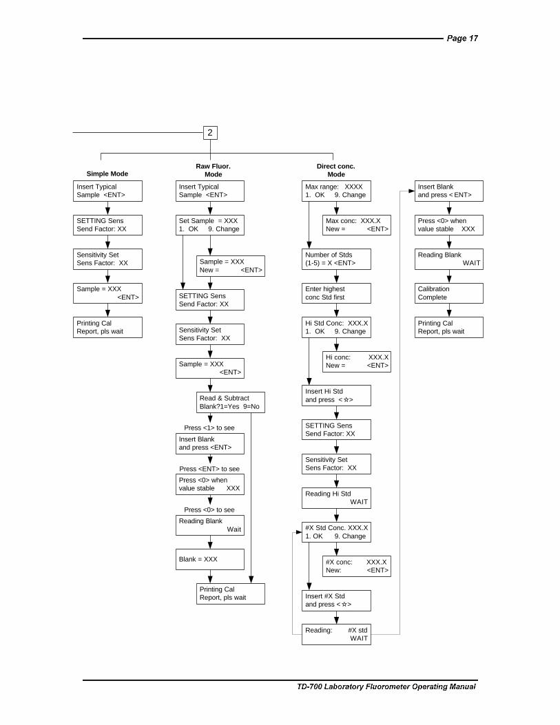
The instrument will initiate the calibration process when <2> of the keypadis pressed from the "Setup/Calibration" Screen. The firmware will guidethe user through the process. Depending upon the calibration mode andprocedure chosen in the Setup screens, the steps will be different. (Seefirmware flowchart on pages 16 & 17). Here is a description of the 3different calibration procedures.
Simple: One point calibrationThis calibration allows you to use one standard (or sample) and noblanks. The instrument gives the standard a relative value of 500 on ascale of 0-1000. The instrument uses a preprogrammed absolutezero as the 0 point.
Multi-Optional/ Raw fluorescence: two point calibration(standard + blank)This calibration allows you to use one standard and the option to blanksubtract. The user can specify the magnitude in relative fluorescenceunits for the standard (on a scale of 0-1000). As an example, if youexpect your standard is ~75% of the full range for the application (seeapplication notes on our website for ranges), then call the standard750 RFUs.
MultiOptional/Direct Concentration: Multi point calibration(up to 5 standards + blank)This calibration allows you to use up to 5 different standards plus ablank for the calibration. You can choose the units of your standards,and define the magnitude of the maximum readable level. In the end,the output can be in direct concentration so no further calculations areneeded.
1. Mode2. Cal Procedure
Raw Fluorescence
1. Mode
Simple Mode
1. Mode 3. Units2. Cal Procedure
Direct Concentration
TD-700 Laboratory Fluorometer Operating Manual
Page 15NOTES

TURNER DESIGNST7-1B 10/96 600
XXX (units)<ENT> Setup &Cal
Sen%: XXXRaw: XXX.XX
1. Mode
Blank?1. Yes 9. No
TURNER DESIGNST7-1B 10/96 600
Data Rate (sec)<1> 2 5 10 30 60
Data Stream?<Yes> No
Oper: XXX HrsPwr Level: 100%
1. Setup2. Calibration
<ENT>
<Simple>Multi-Optional
<Raw Fluor.>Direct Conc.
ppb <ppm> ug/lppt ug/ml ng/ml
BLK XXX (units)<ENT> -Setup &Cal
DLY XXX (units)<ENT> -Setup &Cal
AVE XXX (units)<ENT> -Setup &Cal
END XXX (units)<ENT> -Setup &Cal
1. Mode 3. Units2. Cal Procedure
1. Mode2. Cal Procedure
Simple Mode Direct conc.Mode
Raw Fluor.Mode
1
2
3
K
0
7
8
9
Use the "<->" button on thekeypad to toggle between options
The option in brackets is theselected option
1
Power up ScreenCountdown from 600
Home Screen
Use this screen to choosebetween the Simple modeand the other 2 modes
Use this screen to choosebetween Raw Fluor. anddirect conc. modes
Use this screen to chooseunits to be displayed on thehome screen
Press <ENT> to see
Press <ENT> then <D> to see
Return to homescreen
Read & SubtractBlank?1=Yes 9=No
Insert TypicalSample <ENT>
SETTING SensSend Factor: XX
Sensitivity SetSens Factor: XX
Sample = XXX<ENT>
Printing CalReport, pls wait
Set Sample = XXX1. OK 9. Change
Insert Blankand press <ENT>
Simple ModeRaw Fluor.
ModeDirect conc.
Mode
Sample = XXXNew = <ENT>
Insert TypicalSample <ENT>
SETTING SensSend Factor: XX
Sensitivity SetSens Factor: XX
Sample = XXX<ENT>
Press <0> whenvalue stable XXX
Reading BlankWait
Blank = XXX
Printing CalReport, pls wait
Enter highestconc Std first
Max conc: XXX.XNew = <ENT>
Hi conc: XXX.XNew = <ENT>
Number of Stds(1-5) = X <ENT>
Max range: XXXX1. OK 9. Change
Hi Std Conc: XXX.X1. OK 9. Change
Insert Hi Stdand press < K>
SETTING SensSend Factor: XX
Sensitivity SetSens Factor: XX
Reading Hi StdWAIT
#X Std Conc. XXX.X1. OK 9. Change
#X conc: XXX.XNew: <ENT>
Insert #X Stdand press < K>
Reading: #X stdWAIT
Insert Blankand press < ENT>
Press <0> whenvalue stable XXX
Reading BlankWAIT
Printing CalReport, pls wait
CalibrationComplete
2
Press <ENT> to see
Press <0> to see
Press <1> to see

TD-700 Laboratory Fluorometer Operating Manual
Page 18VI. Calibration Overview
A. Why Calibrate?
The TD-700 calibration procedures set the instrument's sample range,(concentration range) and sensitivity based on a chosen fluorescentstandard or sample. In addition, calibration in the Direct Concentrationmode assigns a digital value to a known standard so that subsequentstandards or samples can be easily referenced to the original. For ex-ample, during Direct Concentration calibration you can assign a value of500 to a sample and know with certain confidence that a sample thatreads 250 contains half as much analyte as the original sample (assumingthat the blank reads zero).
B. When to Calibrate
· For greatest accuracy, calibrate before running a new batch ofsamples.
· Recalibrate if the ambient temperature changes by +/- 5°C.
· Recalibrate after changing lamps, filters, cuvette sizes, or the analyteyou are measuring.
· Verify the need to calibrate by reading a stable, known concentrationstandard immediately after calibration and again every few hours tosee if readings have changed significantly. Recalibrate when theaccuracy becomes unacceptable for your study.
C. TD-700 Calibration Options
There are three calibration procedures available on the TD-700:
· Simple Mode- Raw Fluorescence Calibration· Multi-Optional Mode- Raw Fluorescence Calibration· Multi-Optional Mode- Direct Concentration Calibration
1. Simple Mode Calibration: In the Simple Mode calibration procedurethe instrument range is automatically set based on the typicalstandard or sample chosen. You cannot manually adjust theinstrument range when calibrating in this mode. The chosen samplewill be automatically set to 50% of the maximum value that can beaccurately read by the instrument, (500 out of 1000). Also, there is nooption to read and subtract a blank during this calibration procedure.
2. Multi-Optional Raw Fluorescence Mode: In the Multi-OptionalMode Raw Fluorescence calibration you may manually adjust theinstrument range by changing the default sample value of 500 toanother number from 100 to 950. If you assign a value higher than 500to your chosen sample, you will decrease the maximum sampleconcentration that can be read and increase the instrument’ssensitivity and resolution. If you assign a value lower than 500, youwill increase the maximum concentration that can be read anddecrease the instrument’s sensitivity and resolution.
Note: Calibration data will bestored even after power to theinstrument is turned off.
Note that a separate calibrationis stored for each of the threemodes. For example, if youcalibrate in the Simple Mode,this calibration remains ineffect until you recalibrate inthe Simple Mode. If youcalibrate in the Multi-OptionalMode - Direct Concentration,this will not change thecalibration in the SimpleMode. Similarly, a calibrationin the Multi-Optional Mode -Direct Concentration will notaffect a calibration in theMulti-Optional Mode - RawFluorescence.
Thus, in effect, the TD-700 canstore three separatecalibrations at the same time,one for each mode. This alsomeans that when you changemodes, as each mode is aseparate function, you mustcalibrate in the mode you wantto use.
TD-700 Laboratory Fluorometer Operating Manual
Page 19
3. Direct Concentration Calibration: Direct Concentration Calibration,only available in the Multi-Optional Mode, is a multi-point calibration inwhich up to five standards and a blank are read. The software usesthese points to set the optimal instrument range and sensitivity, and tocalculate the direct concentration of unknowns. In a multi-pointcalibration, the instrument generates a calibration curve for superioraccuracy. The TD-700 will display the actual concentration of yoursamples. The display units are user-selectable and chosen in thesetup menu.
Note: Fluorescence measurements are affected by factors such astemperature, linearity, and instrument drift. Before calibrating orrunning samples for the first time, we recommend reviewing Appendix1.

TD-700 Laboratory Fluorometer Operating Manual
Page 20
1. Setup2. Calibration
1. Setup2. Calibration
Sample = XXX <ENT>
Sensitivity Set Sens Factor: XX
SETTING SensSens Factor: XX
Insert TypicalSample <ENT>
Blank: X.XCal Std: XXX.X
Calibration: Simple Mode
1. Mode
<Simple>Multi-Optional
2.
4.
7.
5.
1.
<1> - Abort Cal<ESC> - Resume
9.
VII. Calibration: Simple Mode
The Simple Mode calibration procedure is a single point calibration in which astandard is run in order to set the optimal range and sensitivity of the instrument.The chosen sample will be set automatically to one half of the maximum value thatcan be accurately read by the instrument. You cannot manually adjust theinstrument range and sensitivity during this procedure. Also, there is no option toread and subtract a blank. If you do not require these capabilities, you may wishto use the Simple Mode calibration as it is expedient and straightforward.
1. To choose the Simple Mode, press <ENT> from the HOME screen, press<1> for Setup, then <1> again for Mode. Use <↔> to choose the SimpleMode. Press <ESC> twice to return to the Setup/Cal Screen.
2. Press <2> from the Setup/Cal Screen. The Simple Mode calibrationsequence will appear.
3. Fill a clean test tube or cuvette with a sample that is about half themaximum concentration you wish to read. You do not need to know theexact concentration; you are using it to set the optimal instrument rangeand sensitivity. Wipe the outside of the test tube or cuvette dry, and insertit into the sample adaptor in the sample chamber.
4. The TD-700 will now set sensitivity, as indicated by the SENS FACTOR(sensitivity factor), so that the sample you inserted will read 500 (half ofmaximum) on the HOME screen.
5. Upon finishing the sensitivity adjustment, the screen prompts you toacknowledge the value set by pressing <ENT>. Then, calibration data willautomatically printout to a printer or a computer and return you to the HOME
screen. See Appendix 2 for details regarding the calibration printout.
6. Errors: After reading the sample, the TD-700 will automatically adjust to the optimal range for sample measurement. If the sample used is too
concentrated or too dilute, the instrument may not be able to reach the targetsensitivity. In these cases, a note message will appear indicating that, basedon the calibration, the unit has reached its sensitivity maximum or minimum.By pressing <ENT> you tell the instrument to accept the maximum orminimum sensitivity value. It is recommended, however, that you adjust yoursample concentrations to fall within range, and then recalibrate.
7. To view the last calibration data set, press <ENT> from the HOME screen,then <9> to view your blank and calibration standard value. Press <H> toreturn to the HOME screen.
8. To print the last calibration data set, press <ENT> from the HOME screen,then <D>. Press <H> to return to the HOME screen.
9. To abort the calibration, press <ESC> at any time during the calibrationsequence. Press <1> to abort or <ESC> to resume.
TD-700 Laboratory Fluorometer Operating Manual
Page 21
NOTES

TD-700 Laboratory Fluorometer Operating Manual
Page 22
VIII. Calibration: Multi-Optional Mode - RawFluorescence
The Multi-Optional Mode - Raw Fluorescence calibration procedure is a singlepoint calibration in which a standard and optional blank are run in order to set theoptimal range and sensitivity of the instrument. The user chooses from a range of100-950 on a scale of 1000, the relative magnitude of the standard. The useralso has the option to subtract the blank signal from all the readings.
1. To choose the Multi-Optional - Raw Fluorescence Mode, press <ENT>from the HOME Screen, press <1> for Setup, then <1> again for Mode.Use <↔> to choose the Multi-Optional Mode. Press <ESC> to return tothe previous screen, then press <2> to choose the calibration procedure.Use the <↔> key to choose “Raw Fluor.” for the Raw Fluorescencecalibration procedure. Press <ESC> twice to return to the Setup/CalScreen.
2. To access the calibration sequence, press <2> from the Setup/CalScreen. The Multi-Optional - Raw Fluorescence calibration sequence willappear.
3. Fill a clean test tube or cuvette with a sample that you wish to read. Youdo not need to know the exact concentration; you are using it to set theoptimal instrument sensitivity and range. Wipe the outside of the test tubeor cuvette dry, and insert it into the sample adaptor in the samplechamber. Press <ENT> to proceed to the next screen.
4. Default setting raw fluorescence reading is 800. If this is acceptable press<1> to continue. If you want to change this value, press <9>. Type in thenew value (between 100 - 950) and press <ENT>. Press <1> to continue.
5. The TD-700 will now set its sensitivity, as indicated by the SENS FACTOR(sensitivity factor), based on the final sample value that you accepted.Once the sample is set, the TD-700 asks whether you want to run a blank.If you wish to have blank subtracted, press <1>. If not, press <9> and thecalibration sequence will end here and you will be returned to the HOMEscreen. At this point, the calibration data will printout automatically to aprinter or a computer. See Appendix 2 for details regarding the calibrationprintout.
Calibration: Multi-OptionalRaw Fluorescence
1. Setup2. Calibration
1. Mode2. Cal Procedure
Simple<Multi-Optional>
1. Mode2. Cal Procedure
<Raw Fluor.>Direct Conc.
1. Mode2. Cal Procedure
1. Setup2. Calibration
Insert TypicalSample <ENT>
SETTING SensSens Factor: XX
Sensitivity Set Sens Factor: XX
Sample = XXX <ENT>
Read & SubtractBlank? 1=Yes 9=No
1.
2.
3.
4.

TD-700 Laboratory Fluorometer Operating Manual
Page 23
6. If you choose to run a blank, fill a clean test tube or cuvette with the blanksolution, wipe the outside of the test tube or cuvette dry, insert it into thesample adaptor in the sample chamber, and press <ENT>. Allow thereading to stabilize and press <0>. The unit will read the blank, thenautomatically return to the HOME screen. At this point, the calibration datawill printout automatically to a printer or a computer. See Appendix 2 fordetails regarding the calibration printout.
7. Errors: After reading the sample, the TD-700 will automatically adjust to theoptimal range for sample measurement. If the sample used is tooconcentrated or too dilute, the instrument may not be able to reach thetarget sensitivity. In these cases, an error message will appear indicatingthat, based on the calibration, the unit has reached its sensitivity maximumor minimum. By pressing <ENT> you tell the instrument to accept themaximum or minimum sensitivity value. It is recommended, however, thatyou adjust your sample concentrations to fall within range, and thenrecalibrate.
8. To view the last calibration data set , press <ENT> from the HOME screen,then <9> to view your blank and calibrating standard value. Press <H> toreturn to the HOME screen.
9. To print the last calibration data set, press <ENT> from the HOME screen,then <D>. Press <H> to return to the HOME screen.
10. To abort the calibration, press <ESC> at any time during the calibrationsequence. Press <1> to abort or <ESC> to resume.
Blank: X.XCal Std: XXX.X
Reading BlankWAIT
Insert Blankand press <ENT>
Press <0> whenvalue stable XXX
Blank = XXX
8.
6.
<1> - Abort Cal<ESC> - Resume
10.
TD-700 Laboratory Fluorometer Operating Manual
Page 24
Max Range: XXXX1. OK 9. Change
Number of Stds(1-5) = X <ENT>
Enter highestconc Std first!
Hi Std Conc: XXX.X1. OK 9. Change
Hi conc: XXX.XNew: <ENT>
2.
5.
4.
Calibration: Multi-OptionalDirect Concentration
1. Setup2. Calibration
1. Mode 3. Units2. Cal Procedure
Simple<Multi-Optional>
1. Mode 3. Units2. Cal Procedure
Raw Fluor.<Direct Conc.>
1. Setup2. Calibration
Max conc: XXX.XNew: <ENT>
3.
1.
Continued on next page
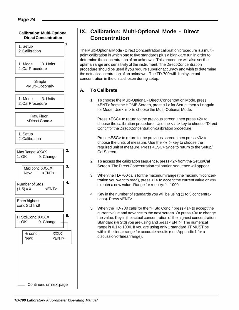
IX. Calibration: Multi-Optional Mode - DirectConcentration
The Multi-Optional Mode - Direct Concentration calibration procedure is a multi-point calibration in which one to five standards plus a blank are run in order todetermine the concentration of an unknown. This procedure will also set theoptimal range and sensitivity of the instrument. The Direct Concentrationprocedure should be used if you require superior accuracy and wish to determinethe actual concentration of an unknown. The TD-700 will display actualconcentration in the units chosen during setup.
A. To Calibrate
1. To choose the Multi-Optional - Direct Concentration Mode, press<ENT> from the HOME Screen, press <1> for Setup, then <1> againfor Mode. Use <↔> to choose the Multi-Optional Mode.
Press <ESC> to return to the previous screen, then press <2> tochoose the calibration procedure. Use the <↔> key to choose “DirectConc” for the Direct Concentration calibration procedure.
Press <ESC> to return to the previous screen, then press <3> tochoose the units of measure. Use the <↔> key to choose therequired unit of measure. Press <ESC> twice to return to the Setup/Cal Screen.
2. To access the calibration sequence, press <2> from the Setup/CalScreen. The Direct Concentration calibration sequence will appear.
3. When the TD-700 calls for the maximum range (the maximum concen-tration you want to read), press <1> to accept the current value or <9>to enter a new value. Range for reentry: 1 - 1000.
4. Key in the number of standards you will be using (1 to 5 concentra-tions). Press <ENT>.
5. When the TD-700 calls for the “HiStd Conc,” press <1> to accept thecurrent value and advance to the next screen. Or press <9> to changethe value. Key in the actual concentration of the highest concentrationStandard (Hi Std) you are using and press <ENT>. The numericalrange is 0.1 to 1000. If you are using only 1 standard, IT MUST bewithin the linear range for accurate results (see Appendix 1 for adiscussion of linear range).

TD-700 Laboratory Fluorometer Operating Manual
Page 25
6. Fill a clean test tube or cuvette with the Hi Std (highest concentrationstandard you are using). Wipe the outside of the cuvette dry and insertit into the sample adaptor in the sample chamber. Press <*>. The unitwill adjust sensitivity (as shown by the SENS FACTOR), to the levelappropriate for that standard then read the standard.
7. If you are using only 1 standard, the TD-700 will prompt you to insertthe Blank. If you are using 2 or more standards, the unit will promptyou to enter the actual concentration of the second standard (#2 Std,as in step 5) and to insert the second standard (#2 Std, as in step 6),then the third (#3 Std), etc. Use a clean, rinsed test tube or cuvetteand insert the next standard; press <*>; then <ENT> when finished.
8. When all the standards have been run, the TD-700 will prompt you toinsert the Blank. Fill a clean test tube or cuvette with the Blank, wipethe outside dry, and insert it into the sample adaptor in the samplechamber. Press <ENT>.
9. Wait for the Blank reading to stabilize, then press <0>. The TD-700will read the Blank, then automatically return to the HOME screen.Calibration data will printout automatically if connected to a printer orcomputer. (See Appendix 2 for details regarding the calibration dataprintout.)
B. How Sample Concentrations will be Calculated
As you have read, the Direct Concentration calibration procedure acceptsmultiple standards and one blank. The concentration vs. fluorescence plotof both the standard and the blank will result in something close to astraight line (assuming the standards are within the linear range of theassay and instrument). If you draw a straight line from point to point on thecalibration plot and record the slope of the line between each point, youcan use these slope values to calculate to sample concentrations. Forexample, the graph below displays a plot of five standards and a blank.Drawing a line between each point will give you five different linearsegments. If the fluorescence of a sample reads between point 2 and point3, the slope of the segment that connects point 2 and point 3 (segment 3)is used to calculate the direct concentration of this sample.
The following equation would be used to calculate sample concentration
0
50
100
150
200
250
300
350
400
0 100 200 300 400 500 600
Actual Concentration of Standards Measured
Segment 3
Point 2
Point 3
Insert Hi Stdand press <*>
SETTING sensSens Factor: XX
6.
#X Std Conc. XXX.X1. OK 9. Change
#X Std Conc. XX.XNew: <ENT>
Insert #X Stdand press <*>
Reading: #XWAIT
7.
Press <0> whenvalue stable XXX
Insert Blankand press <ENT>
Reading BlankWAIT
Blank = XXX
CalibrationComplete
9.
8.
Reading Hi StdWAIT
Sensitivity SetSens Factor: XX
TD-700 Laboratory Fluorometer Operating Manual
Page 26
<1> - Abort Cal<ESC> - Resume
of a sample that had a fluorescence between points 2 and 3:=(Fs - F2) / m3 + C2
Where:- Fs is the fluorescence of the sample- F2 is the fluorescence of standard #2- m3 is the slope of the line between points 2 and 3.- C2 is the concentration of standard #2.
C. To View the Last Calibration
From the HOME Screen, press <ENT> to reach the Setup/Cal screen.From the Setup/Cal screen, press <D> to send the current calibrationinformation to a printer or computer. Press <ESC> to return to theHOME Screen.
D. To Abort the Calibration
To abort the calibration, press <ESC> at any time during the calibrationsequence. Press <1> to abort or <ESC> to resume.

TD-700 Laboratory Fluorometer Operating Manual
Page 27
NOTES
TD-700 Laboratory Fluorometer Operating Manual
Page 28
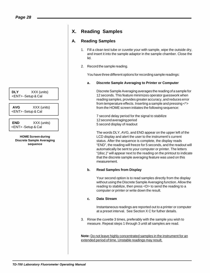
DLY XXX (units)<ENT> -Setup & Cal
AVG XXX (units)<ENT> -Setup & Cal
HOME Screen duringDiscrete Sample Averaging
sequence
END XXX (units)<ENT> -Setup & Cal
X. Reading Samples
A. Reading Samples
1. Fill a clean test tube or cuvette your with sample, wipe the outside dry,and insert it into the sample adaptor in the sample chamber. Close thelid.
2. Record the sample reading.
You have three different options for recording sample readings:
a. Discrete Sample Averaging to Printer or Computer
Discrete Sample Averaging averages the reading of a sample for12 seconds. This feature minimizes operator guesswork whenreading samples, provides greater accuracy, and reduces errorfrom temperature effects. Inserting a sample and pressing <*>from the HOME screen initiates the following sequence:
7 second delay period for the signal to stabilize12 second averaging period5 second display of readout
The words DLY, AVG, and END appear on the upper left of theLCD display and alert the user to the instrument’s currentstatus. After the sequence is complete, the display reads“END”, the reading will freeze for 5 seconds, and the readout willautomatically be sent to your computer or printer. The letters“(disc.)” will appear next to the reading on the printout to indicatethat the discrete sample averaging feature was used on thismeasurement.
b. Read Samples from Display
Your second option is to read samples directly from the displaywithout using the Discrete Sample Averaging function. Allow thereading to stabilize, then press <D> to send the reading to acomputer or printer or write down the result.
c. Data Stream
Instantaneous readings are reported out to a printer or computerat a preset interval. See Section X C for futher details.
3. Rinse the cuvette 3 times, preferably with the sample you wish tomeasure. Repeat steps 1 through 3 until all samples are read.
Note: Do not leave highly concentrated samples in the instrument for anextended period of time. Unstable readings may result.
TD-700 Laboratory Fluorometer Operating Manual
Page 29
B. Resetting Blank to Zero
This feature allows you to reset the blank to zero from the HOME screenwhen in the Multi-Optional Mode. Although running a calibration is the bestmethod to minimize sample error due to instrument drift, a quick and easyway to reduce the effects of dark current, and blank fluorescence, is to"autozero" or "reset the blank to zero" from the HOME screen. However,be sure to run at least one calibration before using this feature. Resettingthe blank to zero from the HOME screen is quite useful if you wish to readmultiple sets of blank and relative sample readings, and do not wish torecalibrate. When resetting the blank to zero, you are replacing the lastblank setting with the new blank setting. Again, this procedure will notcompensate for errors in sample readings due to instrument drift. Formaximum accuracy, you should recalibrate.
1. Insert a blank, then press <0> from the HOME screen.
2. Press <9> to abort the procedure or <1> to Reset Blank to Zero.Press <1> and without further prompting, the instrument will blank tozero.
3. If the reading for the blank exceeds the maximum, the unit will displayan error message: “Blank level too high.” If this message shouldappear, evaluate your sample to ensure that you are reading the blankand not another type of sample. Once you have verified that you arereading the blank, try the procedure again. If the message persists,recalibrate the instrument.
C. Data Stream
This feature allows you to output data directly to a printer or a computer atregular intervals. Only the value seen on the LCD screen will be printed. Noindex or raw fluorescence value will be printed.
1. Press <7> from the HOME screen.
2. Press <↔> to toggle between <Yes> and <No> (turns data stream onor off).
When the data stream feature is on, the data rate can be changed. Thenumber selected is the time interval between data output.
1. Press <D> from the HOME screen when the data stream feature is on.
2. Use the <↔> key to toggle between numbers.
BLK XXX ppm<ENT> -Setup & Cal
Blank?1. Yes 9. No
Data Stream?Yes <No>
Data Rate (sec)<1> 2 5 10 30 60

TD-700 Laboratory Fluorometer Operating Manual
Page 30
APPENDIX 1Before Calibration or Reading Samples
A. Materials Needed
- 1 or more cuvettes (25 mm test tubes; 13 mm test tubes or 10 mmsquare cuvettes).
- A Blank (sample water or liquid containing none of the fluorescentmaterial) (except when using the instrument in Simple Mode).
- Standard(s) (1 to 5 solutions of varying but known concentrations) forthe Direct Concentration Calibration Procedure; OR, for the Simplemode, one standard that is approximately half the level of the highestsample you are likely to read (used to set the optimal sensitivity andrange of the TD-700).
- Samples to be read.
B. When Handling Samples
1. Take care not to spill samples into the sample chamber. Wipe up anyspills promptly. See Appendix 9, Section A, for details on mainte-nance.
2. Rinse the test tube or cuvette 3 times between samples (preferablywith the sample to be read). The TD-700 is very sensitive and evensmall amounts of material from a previous sample may result in errors.Complete rinsing is especially important if you are using the same testtube or cuvette for samples and blank.
3. Fill the test tube or cuvette at least 75% full; significant error will resultif it is not full enough.
4. The cuvette MUST BE DRY on the outside when taking readings.Moisture on the outside will result in error.
C. Linear Range and “Quenching”
The linear range is the concentration range in which the readout of the TD-700 is directly proportional to the analyte concentration. The linear rangebegins with the smallest detectable concentration and spans to an upperlimit (concentration) that is dependent upon: the properties of the fluores-cent material, the filters used, and the path length.
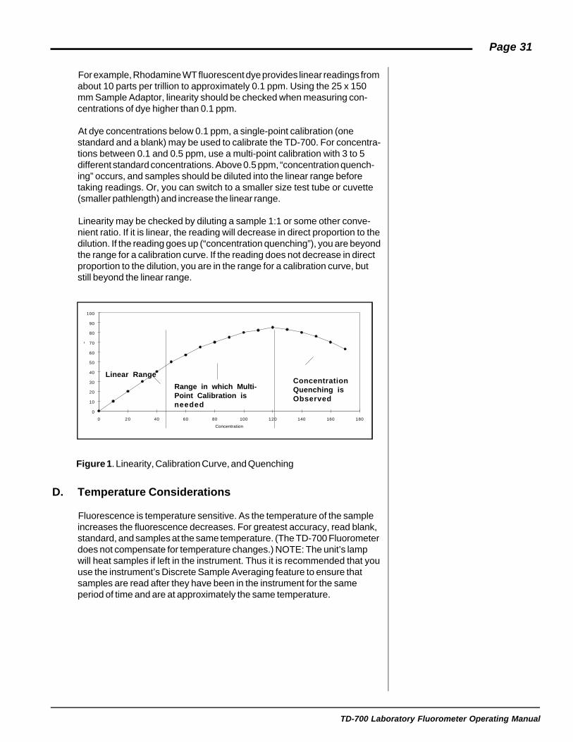
Beyond the linear range (above the upper concentration limit), the fluores-cence readings rise at a decreasing rate and a calibration curve is neces-sary for accurate readings. At even higher concentrations, readings willbegin to decrease even though the sample concentration is increasing.This effect is known as "concentration quenching".
TD-700 Laboratory Fluorometer Operating Manual
Page 31
For example, Rhodamine WT fluorescent dye provides linear readings fromabout 10 parts per trillion to approximately 0.1 ppm. Using the 25 x 150mm Sample Adaptor, linearity should be checked when measuring con-centrations of dye higher than 0.1 ppm.
At dye concentrations below 0.1 ppm, a single-point calibration (onestandard and a blank) may be used to calibrate the TD-700. For concentra-tions between 0.1 and 0.5 ppm, use a multi-point calibration with 3 to 5different standard concentrations. Above 0.5 ppm, “concentration quench-ing” occurs, and samples should be diluted into the linear range beforetaking readings. Or, you can switch to a smaller size test tube or cuvette(smaller pathlength) and increase the linear range.
Linearity may be checked by diluting a sample 1:1 or some other conve-nient ratio. If it is linear, the reading will decrease in direct proportion to thedilution. If the reading goes up (“concentration quenching”), you are beyondthe range for a calibration curve. If the reading does not decrease in directproportion to the dilution, you are in the range for a calibration curve, butstill beyond the linear range.
D. Temperature Considerations
Fluorescence is temperature sensitive. As the temperature of the sampleincreases the fluorescence decreases. For greatest accuracy, read blank,standard, and samples at the same temperature. (The TD-700 Fluorometerdoes not compensate for temperature changes.) NOTE: The unit’s lampwill heat samples if left in the instrument. Thus it is recommended that youuse the instrument’s Discrete Sample Averaging feature to ensure thatsamples are read after they have been in the instrument for the sameperiod of time and are at approximately the same temperature.
Concentration
Flu
orom
eter
Rea
ding
0
10
20
30
40
50
60
70
80
90
100
0 20 40 60 80 100 120 140 160 180
Linear Range
Range in which Multi-Point Calibration isneeded
ConcentrationQuenching isObserved
Figure 1. Linearity, Calibration Curve, and Quenching

TD-700 Laboratory Fluorometer Operating Manual
Page 32
E. Positioning Samples
Sample cuvettes often will give slightly different measurements dependingupon their orientation in the sample adaptor. This is due to defects in theshape of the test tube that are not visible to the human eye. We recom-mend that the test tube be marked at the top and positioned in the adaptorthe same way each time to minimize error.
F. Data Quality
The TD-700 is only as accurate as the standards that are used to calibrateit. This is why it is important to take care when preparing standards,samples, and blanks. One should follow good laboratory practices whenpreparing these standards.

TD-700 Laboratory Fluorometer Operating Manual
Page 33
APPENDIX 2The Calibration Printout
A. Printout Capability with a Printer or Computer
To use this function with a printer:
1. Connect the TD-700 to a serial printer via the RS-232 port on the backof the instrument. If you ordered a printer from Turner Designs, theappropriate serial cable is included.
2. Press <D> or <*> from the HOME screen and the readout currentlydisplayed will be sent to the printer.
To use this function with a computer:
1. Connect the TD-700 to your computer via the RS-232 port on the backof the instrument. Use the DB9 serial cable included with your instru-ment.
2. The TD-700 signal is in ASCII format so you can use various communi-cations programs to import data to your computer. On your computer,run the communications program you have chosen. For a step-by-stepprocedure using Microsoft Windows terminal, see Appendix 5.
3. Press <D> or <*> from the HOME screen and the readout currentlydisplayed will be sent to the computer with an index number.
B. Sample Reading with a Printer or Computer
When <D> or <*> is pressed from the HOME Screen, the TD-700 sendsout an index marker (1 - 999), the concentration readout of the sample,and the Raw Fluorescence (all in ASCII format). Note that the columnheadings will appear only before the first index, and the index will beginagain from “1” every time you calibrate or turn off the instrument. Anexample of the indexing feature is illustrated by the left column in thesample printout below.
In the Direct Concentration Calibration Procedure (for example only):
Samples: Conc. Raw Fluor.1 32.01 42.802 16.00 21.403 8.002 10.70
For the Simple and Raw Fluorescence modes (for example only):
Samples: Raw Fluor.1 42.802 21.403 10.70
TD-700 Laboratory Fluorometer Operating Manual
Page 34
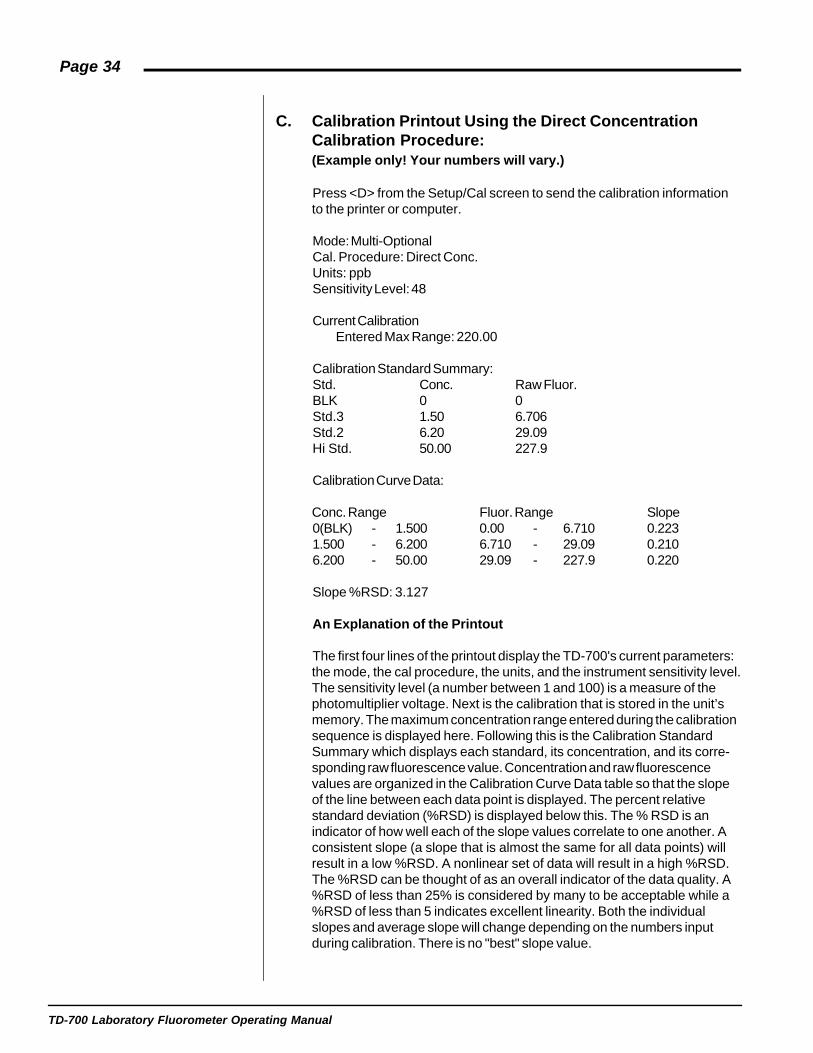
C. Calibration Printout Using the Direct ConcentrationCalibration Procedure:(Example only! Your numbers will vary.)
Press <D> from the Setup/Cal screen to send the calibration informationto the printer or computer.
Mode: Multi-OptionalCal. Procedure: Direct Conc.Units: ppbSensitivity Level: 48
Current CalibrationEntered Max Range: 220.00
Calibration Standard Summary:Std. Conc. Raw Fluor.BLK 0 0Std.3 1.50 6.706Std.2 6.20 29.09Hi Std. 50.00 227.9
Calibration Curve Data:
Conc. Range Fluor. Range Slope0(BLK) - 1.500 0.00 - 6.710 0.2231.500 - 6.200 6.710 - 29.09 0.2106.200 - 50.00 29.09 - 227.9 0.220
Slope %RSD: 3.127
An Explanation of the Printout
The first four lines of the printout display the TD-700's current parameters:the mode, the cal procedure, the units, and the instrument sensitivity level.The sensitivity level (a number between 1 and 100) is a measure of thephotomultiplier voltage. Next is the calibration that is stored in the unit’smemory. The maximum concentration range entered during the calibrationsequence is displayed here. Following this is the Calibration StandardSummary which displays each standard, its concentration, and its corre-sponding raw fluorescence value. Concentration and raw fluorescencevalues are organized in the Calibration Curve Data table so that the slopeof the line between each data point is displayed. The percent relativestandard deviation (%RSD) is displayed below this. The % RSD is anindicator of how well each of the slope values correlate to one another. Aconsistent slope (a slope that is almost the same for all data points) willresult in a low %RSD. A nonlinear set of data will result in a high %RSD.The %RSD can be thought of as an overall indicator of the data quality. A%RSD of less than 25% is considered by many to be acceptable while a%RSD of less than 5 indicates excellent linearity. Both the individualslopes and average slope will change depending on the numbers inputduring calibration. There is no "best" slope value.
TD-700 Laboratory Fluorometer Operating Manual
Page 35
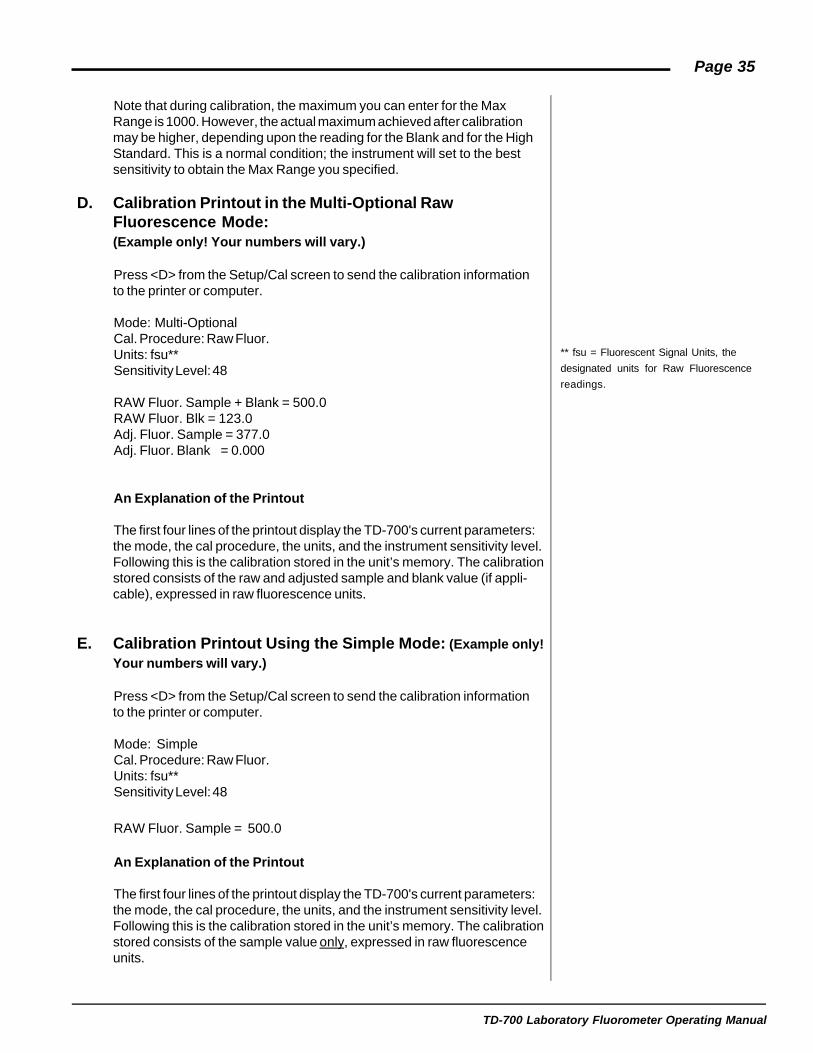
Note that during calibration, the maximum you can enter for the MaxRange is 1000. However, the actual maximum achieved after calibrationmay be higher, depending upon the reading for the Blank and for the HighStandard. This is a normal condition; the instrument will set to the bestsensitivity to obtain the Max Range you specified.
D. Calibration Printout in the Multi-Optional RawFluorescence Mode:(Example only! Your numbers will vary.)
Press <D> from the Setup/Cal screen to send the calibration informationto the printer or computer.
Mode: Multi-OptionalCal. Procedure: Raw Fluor.Units: fsu**Sensitivity Level: 48
RAW Fluor. Sample + Blank = 500.0RAW Fluor. Blk = 123.0Adj. Fluor. Sample = 377.0Adj. Fluor. Blank = 0.000
An Explanation of the Printout
The first four lines of the printout display the TD-700's current parameters:the mode, the cal procedure, the units, and the instrument sensitivity level.Following this is the calibration stored in the unit’s memory. The calibrationstored consists of the raw and adjusted sample and blank value (if appli-cable), expressed in raw fluorescence units.
E. Calibration Printout Using the Simple Mode: (Example only!Your numbers will vary.)
Press <D> from the Setup/Cal screen to send the calibration informationto the printer or computer.
Mode: SimpleCal. Procedure: Raw Fluor.Units: fsu**Sensitivity Level: 48
RAW Fluor. Sample = 500.0
An Explanation of the Printout
The first four lines of the printout display the TD-700's current parameters:the mode, the cal procedure, the units, and the instrument sensitivity level.Following this is the calibration stored in the unit’s memory. The calibrationstored consists of the sample value only, expressed in raw fluorescenceunits.
** fsu = Fluorescent Signal Units, the
designated units for Raw Fluorescence
readings.

TD-700 Laboratory Fluorometer Operating Manual
Page 36
APPENDIX 3Alarms and Diagnostics
A. Alarm Screen
There are alarms built into the TD-700 to warn of an internal instrumentmalfunction or low power.
Table 1. Alarms
Alarm Delay Alarm Condition Normal
High Voltage (HV Bad) 3 min. >1000 or <25 V 150 to 850
Low Power (Low PWR) 1 min. <40% 100%
An alarm will be activated if the abnormal condition is in effect for aspecified delay period. If an alarm is activated, “ALM” will blink on theHOME screen.
To see what alarm is active, from the home screen press <ESC>. Forexample, if the high voltage (HV) is outside the specified range you will see"HV Bad". If the HV alarm is triggered (HV Bad is seen when <ESC> ispressed from the HOME screen), contact Turner Designs.
If the low power alarm is triggered, check the power at the source and thepower supply.
Refer to the Diagnostic Screens (next section) for definitions.
B. Diagnostic Screens
There are diagnostic screens which show the status of internal fluorometerfunctions. To access these screens, from the HOME screen, press <8>,then <ENT> to see the next screen in the sequence.
Definitions:
Sen %. Sen % is also referred to as Sens Factor in the software andSensitivity Level on the printout. All three terms indicate the fluorometer'ssensitivity on a scale of 1 to 100. The Sen % is directly proportional to thevoltage on the photomultiplier tube. The higher the number, the greater thephotomultiplier tube voltage, the greater the sensitivity (and typically, thegreater the "noise") of the readings.
ALM XXX ppm<ENT> -Setup & Cal
HV Bad
Sen %: XXRaw: XXX
Oper: XXX HrsPower level: 100%

TD-700 Laboratory Fluorometer Operating Manual
Page 37
Raw. The “raw” fluorescence signal output from the instrument’s lightdetector (the photomultiplier tube). This is the output the TD-700 uses (inconjunction with the actual value entered for the standards, and thefluorescence signal for standards and blank) to arrive at the readout on theHOME screen. It can be used to diagnose problems with the unit.
NOTE: To see the raw fluorescence for the standard(s) and the blank asset during the last calibration, from the Calibration & Setup menu, press<D> to print or send to a computer.
NOTE: If you calibrated in the Simple Mode or Multi-Optional Mode “RawFluor.” Calibration Procedure, to see the raw fluorescence for the standardand the blank as set during the last calibration, from the Calibration &Setup menu, press <9> and they will appear on the display.
Operation Hour (Oper). Shows how many hours the instrument has beenoperating.
Power level. When at 100%, indicates power supply is functioningcorrectly.

TD-700 Laboratory Fluorometer Operating Manual
Page 38
APPENDIX 4Troubleshooting
Symptom Solution Section To See
Power ON but Check the lamp; change if necessary. Section IVreadings stay Make sure the sample lid is closedat zero tightly.
Power switch Make sure unit is plugged in securely;ON, but no check power from the wall socket; Makepower sure power supply is functioning.
Display reads Sample reading is too high for the Appendix 8, H.OVER instrument to read at the current
sensitivity level. Dilute samples to getan on-scale reading. Or recalibrate andreduce sensitivity.
Display reads Reading for Blank is less than zero Appendix 8, H.negative (-) due to drift; reading for samples are
less than Blank. Reset Blank to Zeroor recalibrate.
Drifting The instrument is open loop and Section VIIreadings readings will drift over a period of time; Section VIII
recalibrate to cure. Section IX
Erratic readings Instrument readings will fluctuate Section IIIsomewhat due to instrument noise, Section IVespecially at high sensitivity and whenreading low concentrations. If readingsare very erratic, check the lamp andoptical filters for damage/freckling.
Low readings; Sensitivity was not adjusted adequately Section VIInot enough during calibration; recalibrate. Or, make Section VIIIresolution sure the proper lamp and filters are Section IX
being used. Section IIISection IV

TD-700 Laboratory Fluorometer Operating Manual
Page 39
APPENDIX 5Data Collection
You can use various communications software programs to import data to yourcomputer. The signal is sent from the TD-700 in ASCII format.
1. Connect the 9-pin connector that extends from the TD-700 to the serialcommunications port of your computer (COM1 or COM2) using a 9-pinserial cable. You may need a 9-to-25 pin serial adaptor. Obtain this at yourlocal computer store.
2. In Window's OS, locate the HyperTerminal program in the Accessories directory and double-click on the icon to open it. If operating in MAC OS, use a comparable terminal program to capture the ASCII data.
3. Give the New Connection a name such as TD700.
4. In the Phone Number window, choose Direct to COM 1 or Direct to COM 2 depending on which COM Port that the instrument is connected to. (This can be the hardest part of the procedure. Different computer manufacturers use different conventions.)
5. Set the Port Settings to the following parameters : Bits per second: 9600, Data Bits: 8, Parity: none, Stop Bits: 1, Flow Control: Xon/Xoff.
6. To store the data to a file, choose the Transfer menu and select Capture. Give the captured file a name.
7. Stop the Capture when you are done by selecting the Transfer menu, and then by selecting Capture/Stop.
8. Access your data using Excel, Word, or other programs by opening the file you saved in step 6.

TD-700 Laboratory Fluorometer Operating Manual
Page 40
APPENDIX 6Sample and Cuvette Adapters
Test tube and cuvette size, apertures, and the sample cell path length all affectthe sensitivity of the instrument. In general, the greater the diameter of the testtube or cuvette (the greater the path length), the more sensitive the readings andthe lower the linear range.
The smaller the window and path length, the less sensitive the readings.
You must recalibrate the instrument if you change cuvette adapters, or if youchange path lengths or attenuators.
A. Installing and Removing Sample Adapters
Available for the TD-700 are a variety of sample adapter to cater to thesample size needs of researchers. These are :
-25 mm test tube adapter (P/N 7000-982, standard with TD-700 model 7000-000)
-13 mm test tube adapter (P/N 7000-981, standard with TD-700 model 7000-000)
-10x10 mm square cuvette adapter (PN 7000-988, standard with TD-700 model 7000-009)
-Minicell adapter (P/N 7000-951, fits inside 10x10 cuvettes adapter P/N 7000-009)
To install/use adapters
1. Open the lid to the sample chamber.
2. Align pin or point arrow on the adapter to the silver dot on the TD-700.
3. Slide the sample adaptor inside the sample chamber and push downuntil it is fully seated in the chamber.
To remove sample adapter:
1. Open the lid to the sample chamber.
2. Remove the test tube.
3. Grasp the sample adaptor by the rim and pull straight up.

TD-700 Laboratory Fluorometer Operating Manual
Page 41
B. Minicell Adapter
The minicell cuvettes allows for very small volumes (75-250µl) to beanalyzed.
To install
1. Slide minicell adapter into the 10x10 mm cuvette adapter, where a normal cuvette would sit.
2. Insert the borosilicate glass minicell into the adapter.
3. Insert into the TD-700 as described earlier.

TD-700 Laboratory Fluorometer Operating Manual
Page 42
APPENDIX 7Glossary
Accuracy The degree to which a measured result approximatesthe true value of the quantity being measured. This valueis usually expressed as a percent.
Analyte The substance you wish to measure.
Attenuator A part used to cut down the amount of light that entersand exits the sample. Can be used to adjust thesensitivity and dynamic range of your analysis.
Blank Sample water that contains none of the fluorescentmaterial to be measured. Blank is used during calibra-tion to set the instrument to zero.
Calibration Setting the sensitivity of the instrument to the standardand “zeroing” the instrument to subtract blank.
Calibration Curve See Linearity. By using multiple standards duringcalibration in the Direct Concentration calibrationprocedure, a calibration curve will be obtained, whichwill provide accurate readings even when the readingsare nonlinear.
Dark Current A small amount of current flows in a photomultiplier tubeeven when the tube is operated in a completely darkstate. This output is called dark current and the magni-tude is greatly dependent upon the amount of voltageapplied to the photomultiplier tube (i.e. the greater theSensitivity Factor, the larger the dark current).
Detection Limit May be used to refer to either the minimum or maxi-mum concentration that can be read. Limits are specificto the fluorescent material, filters, lamp, and sample orcuvette adaptor used.
Direct Concentration Refers to the actual concentration of the substancebeing read. “Direct Concentration” is a user-selectedTD-700 calibration procedure which, after calibration,provides the actual concentration of samples in theunits selected by the user.
Discrete SampleAveraging A feature of the TD-700 which allows a sample reading
to be averaged over a set period of time, which mini-mizes operator guesswork, temperature effects, andinconsistent sample handling. When <*> is pressedfrom the HOME screen, after a 7-second delay, thesignal will be averaged for 12 seconds, and the averagedisplayed for 5 seconds.

TD-700 Laboratory Fluorometer Operating Manual
Page 43
Drift The change in measurement of the same sample overtime.
Dynamic Range(maximum range) The range of concentrations that can be read by the TD-
700 at the current level of sensitivity. Since zero isfrequently assumed to be the minimum, dynamic rangein this manual often refers to the maximum concentra-tion that can be read. The user can select the desiredmaximum (Max Range) during calibration in the DirectConcentration calibration procedure.
Fluorescence The TD-700 Fluorometer measures the concentration ofvarious analytes in samples of interest via fluorescence.A fluorescent molecule has the ability to absorb light atone wavelength and almost instantly emit light at a newand longer wavelength. A fluorescent molecule has aunique “fluorescence signature,” which allows onesubstance to be distinguished from another. In afluorometer, light from a lamp is passed through anexcitation filter that transmits light of a wavelength rangespecific to the sample compound being measured. Thelight passes through the sample, which emits lightproportional to the concentration of the fluorescentmaterial present and proportional to the intensity of theexciting light. The emitted light is passed through anemission filter that selects for the appropriate wave-length range, and the resultant light is then detected bya photomultiplier tube.
Gain An indicator of the sensitivity of the instrument usuallyexpressed in powers of 10.
Linear Range The concentration range in which standards correlatewith a straight line. Usually expressed as a concentra-tion maximum such as 100 ppb.
Noise The amount of fluctuation in the instrument's measure-ment due to the instrument or detector itself.
Optical Path Length The length of sample through which light passes. Thisis defined by the cuvette size and adaptor used.
Quenching A phenomenon which occurs when the fluorescencemeasurements decrease even though analyte concen-tration is increasing.
Raw Fluorescence Refers to the “relative” fluorescence of a substancebeing read, rather than the actual concentration. “RawFluorescence” is a user-selected TD-700 calibrationprocedure which, after calibration, provides the “fluores-cence intensity” of samples relative to the standard andto each other.

TD-700 Laboratory Fluorometer Operating Manual
Page 44
Resolution Resolution is related to sensitivity, but refers to the“detail” which can be read. When the instrumentsensitivity level is high, lower concentrations can beread with ease (high resolution) but higher concentra-tions can not be read on-scale. When the sensitivity islow, higher concentrations can be read, but the detail isnot as good at low concentrations (low resolution).
Sens Factor These three terms are synonymous and are used toSen % indicate the TD-700 fluorometer's sensitivity on aSensitivity Level scale of 1 to 100. Sens Factor is the term used in the
software during calibration, Sens % can be found on thediagnostic screen, and sensitivity level is the term usedon the printout. The Sensitivity Factor is directlyproportional to the voltage on the photomultiplier tube.The higher the Sensitivity Factor, the greater thesensitivity (and typically, the greater the "noise") of thereadings.
Sensitivity The basic operating level of the instrument. It is relatedto the detection limits, the dynamic range, and theresolution. The electronic sensitivity is set duringcalibration using the keypad. Sensitivity can also beadjusted mechanically using different cuvette sizes.
TD-700 Laboratory Fluorometer Operating Manual
Page 45
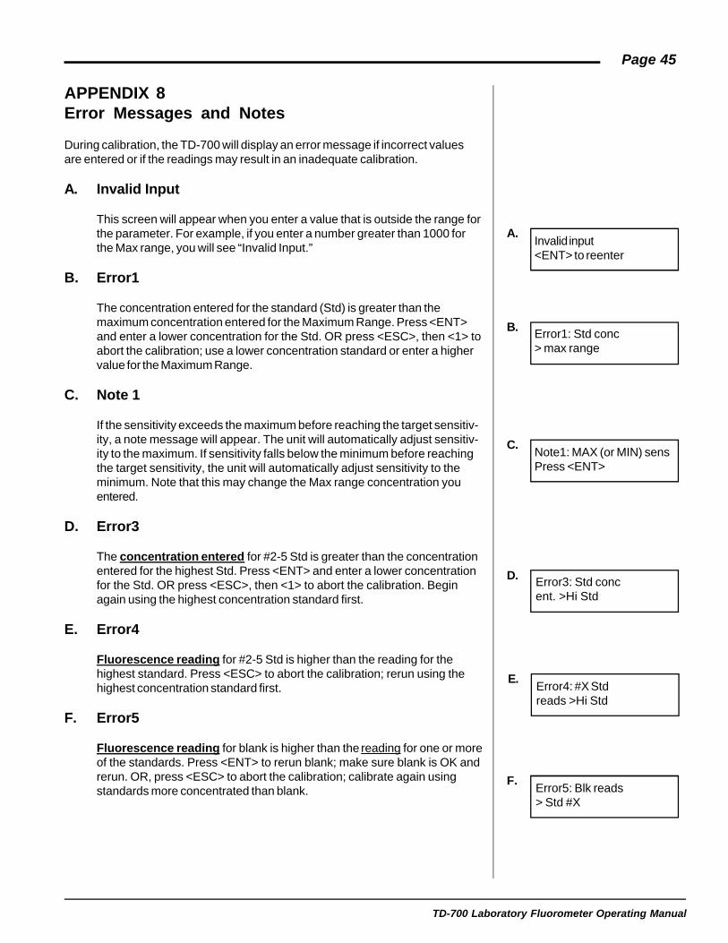
APPENDIX 8Error Messages and Notes
During calibration, the TD-700 will display an error message if incorrect valuesare entered or if the readings may result in an inadequate calibration.
A. Invalid Input
This screen will appear when you enter a value that is outside the range forthe parameter. For example, if you enter a number greater than 1000 forthe Max range, you will see “Invalid Input.”
B. Error1
The concentration entered for the standard (Std) is greater than themaximum concentration entered for the Maximum Range. Press <ENT>and enter a lower concentration for the Std. OR press <ESC>, then <1> toabort the calibration; use a lower concentration standard or enter a highervalue for the Maximum Range.
C. Note 1
If the sensitivity exceeds the maximum before reaching the target sensitiv-ity, a note message will appear. The unit will automatically adjust sensitiv-ity to the maximum. If sensitivity falls below the minimum before reachingthe target sensitivity, the unit will automatically adjust sensitivity to theminimum. Note that this may change the Max range concentration youentered.
D. Error3
The concentration entered for #2-5 Std is greater than the concentrationentered for the highest Std. Press <ENT> and enter a lower concentrationfor the Std. OR press <ESC>, then <1> to abort the calibration. Beginagain using the highest concentration standard first.
E. Error4
Fluorescence reading for #2-5 Std is higher than the reading for thehighest standard. Press <ESC> to abort the calibration; rerun using thehighest concentration standard first.
F. Error5
Fluorescence reading for blank is higher than the reading for one or moreof the standards. Press <ENT> to rerun blank; make sure blank is OK andrerun. OR, press <ESC> to abort the calibration; calibrate again usingstandards more concentrated than blank.
Invalid input<ENT> to reenter
A.
Error1: Std conc> max range
B.
Note1: MAX (or MIN) sensPress <ENT>
C.
D.
E.
Error3: Std concent. >Hi Std
Error4: #X Stdreads >Hi Std
Error5: Blk reads> Std #X
F.
TD-700 Laboratory Fluorometer Operating Manual
Page 46
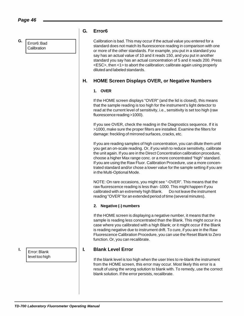
G. Error6
Calibration is bad. This may occur if the actual value you entered for astandard does not match its fluorescence reading in comparison with oneor more of the other standards. For example, you put in a standard yousay has an actual value of 10 and it reads 150, and you put in anotherstandard you say has an actual concentration of 5 and it reads 200. Press<ESC>, then <1> to abort the calibration; calibrate again using properlydiluted and labeled standards.
H. HOME Screen Displays OVER, or Negative Numbers
1. OVER
If the HOME screen displays “OVER” (and the lid is closed), this meansthat the sample reading is too high for the instrument’s light detector toread at the current level of sensitivity, i.e., sensitivity is set too high (rawfluorescence reading >1000).
If you see OVER, check the reading in the Diagnostics sequence. If it is>1000, make sure the proper filters are installed. Examine the filters fordamage: freckling of mirrored surfaces, cracks, etc.
If you are reading samples of high concentration, you can dilute them untilyou get an on-scale reading. Or, if you wish to reduce sensitivity, calibratethe unit again. If you are in the Direct Concentration calibration procedure,choose a higher Max range conc. or a more concentrated “high” standard.If you are using the Raw Fluor. Calibration Procedure, use a more concen-trated standard and/or chose a lower value for the sample setting if you arein the Multi-Optional Mode.
NOTE: On rare occasions, you might see “-OVER”. This means that theraw fluorescence reading is less than -1000. This might happen if youcalibrated with an extremely high Blank. Do not leave the instrumentreading "OVER" for an extended period of time (several minutes).
2. Negative (-) numbers
If the HOME screen is displaying a negative number, it means that thesample is reading less concentrated than the Blank. This might occur in acase where you calibrated with a high Blank; or it might occur if the Blankis reading negative due to instrument drift. To cure, if you are in the RawFluorescence Calibration Procedure, you can use the Reset Blank to Zerofunction. Or, you can recalibrate.
I. Blank Level Error
If the blank level is too high when the user tries to re-blank the instrumentfrom the HOME screen, this error may occur. Most likely this error is aresult of using the wrong solution to blank with. To remedy, use the correctblank solution. If the error persists, recalibrate.
Error6: BadCalibration
G.
Error: Blanklevel too high
I.

TD-700 Laboratory Fluorometer Operating Manual
Page 47
APPENDIX 9Maintenance, Warranty, & Service
A. Maintenance
If possible, do not spill liquids into the sample chamber. However, there isa drain plug on the bottom of the instrument underneath the cuvetteadaptor. If there is a spill:
1. Unplug the instrument.
2. Remove the test tube or cuvette, the sample adaptor, and FilterCylinder from the instrument. Completely dry all of these items and theoptical filters.
3. Wipe up any moisture inside the sample chamber.
4. Plug in the unit and turn on the power. Allow it to run for a few hoursuntil completely dry inside.
Periodically wipe off the outside of the instrument with a damp cloth. Donot use solvents or abrasive cleaners to clean the TD-700.
B. Warranty
Turner Designs warrants the TD-700 Fluorometer and accessories to befree from defects in materials and workmanship under normal use andservice for a period of one year from the time of initial purchase, with thefollowing restrictions:
1. The instrument and accessories must be installed, powered, andoperated in compliance with the directions in this TD-700 LaboratoryFluorometer Operating Manual and directions accompanying theaccessories.
2. Damage incurred in shipping is not covered.
3. Damage resulting from measurement of samples found to be incom-patible with the materials used in the sample system is not covered.
4. Damage resulting from contact with corrosive materials or atmosphereis not covered.
5. Damage from sea water and other moderately corrosive materials thatare not promptly removed from the instrument is not covered.
6. Damage caused by modification of the instrument by the customer isnot covered.
7. Failure of limited life parts, such as lamps, is not covered.

TD-700 Laboratory Fluorometer Operating Manual
Page 48
C. Obtaining Service
Warranty Service
To obtain service during the warranty period, the owner shall take thefollowing steps:
1. Write or call the Turner Designs service department and describe asprecisely as possible the nature of the problem.
2. Carry out minor adjustments or tests as suggested by the ServiceDepartment.
3. If proper performance is not obtained, ship the instrument, prepaid, toTurner Designs, with a statement of shipping charges. The instrumentwill be repaired and returned free of charge, along with a check tocover shipping charges, for all customers in the contiguous continentalUnited States.
For customers outside of the contiguous continental United States,and who have purchased our equipment from one of our authorizeddistributors, contact the distributor. If you have purchased direct,contact us. We will repair the instrument at no charge, but we will notpay for shipment, documentation, etc. These charges will be billed atcost.
NOTE! Under no conditions should the instrument or accessories bereturned without notice. Prior correspondence is needed:
a. To ensure that the problem is not a trivial one, easily handled inyour laboratory, with consequent savings to everyone.
b. To specifically determine the nature of the problem, so thatrepair can be rapid, with particular attention paid to the defectyou have noted.
Out-of-Warranty Service
Proceed exactly as for Warranty Service, above. If our service departmentcan assist you by phone or correspondence, we will be glad to, at nocharge.
Repair service will be billed on a basis of time and materials. A completestatement of time spent and materials used will be supplied. Shipment toTurner Designs should be prepaid. Your bill will include return shipmentfreight charges.
Address for Shipment:Turner Designs
845 W. Maude Ave.Sunnyvale, CA 94085

TD-700 Laboratory Fluorometer Operating Manual
Page 49
APPENDIX 10Specifications and Features
Sample Adaptors: 25 mm sample adaptor accommodates 25 x150 mm test tubes, a 13 mm sample adaptorfor 13 x 100 mm test tubes, and an adaptor for10 x 10 x 45 mm square cuvettes. A RangeExtending Adaptor with variable apertures for10 x 10 x 45 mm square cuvettes is alsoavailable.
Sensitivity: Less than 20 picograms/ml FITC.
Power: External power supply, 100-240 VAC +/- 10%of the nominal voltage, Max. 30 watts.
Dimensions: 23.5 cm W x 28 cm D x 21 cm H, (9.25" W x11" D x 8.25" H).
Weight: 5.9 Kg (13 lbs).
Operating Temperature: 41 - 104°F; 5 - 40°C.
Display: 16 x 2 character LCD; (3.86" x .86"; 9.8 cm x2.18 cm).
Keypad: 4 x 5 keys (3" x 2.7"; 7.62 cm x 6.86 cm).
Data Output: 100% ASCII format through a 9-pin RS-232serial cable at 9600 baud.
Filter Cylinder: Accommodates eight, 1-inch round filters, (fourexcitation and four emission).
Software: Menu-driven microprocessor-controlled.
Detector: Factory-installed photomultiplier tube. Stan-dard: 300 - 650 nm. Optional Red Sensitive:185 - 870 nm.
Lamp: Quartz Halogen Lamp (20 watts; Lamp Life =2000 hours) or Low Pressure Mercury VaporLamp (4 watts; Lamp Life = 8000 hours).
Printer: Optional SeikoTM
Printer (16.0 cm W x 17.0 cm D x
6.7 cm H).
Material: UL-approved polyurethane. Sheet metal backand base.
Readout: Direct Concentration or Raw Fluorescence.
Environmental Conditions: Indoor use only. Altitude specification: 0-2000m. Transient Overvoltages according toINSTALLATION CATEGORY II. PollutionDegree 1 and 2 in accordance with IEC 664.
TD-700 Laboratory Fluorometer Operating Manual
Page 50
Maximum Relative Humidity: 75% for temperatures up to 31oC, decreasinglinearly to 50% relative humidity at 40oC.
Calibration: Multi-point Calibration for Direct ConcentrationMeasurement or Single Point Raw Fluores-cence Calibration.
Operating Mode: "Simple" for the inexperienced user; or "Multi-Optional" for the advanced user.
Blank: Reads and subtracts Blank.
Discrete Sample Averaging: Sample readings can be averaged to improveaccuracy (7-second delay; 12-second signalaveraging; 5-second display readout).
Warranty: One-year warranty.
Approvals: CE, TUV, and UL.
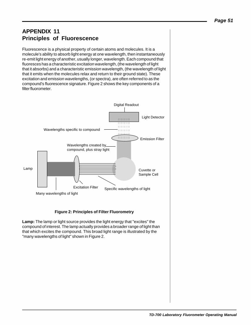
TD-700 Laboratory Fluorometer Operating Manual
Page 51
APPENDIX 11Principles of Fluorescence
Fluorescence is a physical property of certain atoms and molecules. It is amolecule's ability to absorb light energy at one wavelength, then instantaneouslyre-emit light energy of another, usually longer, wavelength. Each compound thatfluoresces has a characteristic excitation wavelength, (the wavelength of lightthat it absorbs) and a characteristic emission wavelength, (the wavelength of lightthat it emits when the molecules relax and return to their ground state). Theseexcitation and emission wavelengths, (or spectra), are often referred to as thecompound's fluorescence signature. Figure 2 shows the key components of afilter fluorometer.
Figure 2: Principles of Filter Fluorometry
Lamp: The lamp or light source provides the light energy that "excites" thecompound of interest. The lamp actually provides a broader range of light thanthat which excites the compound. This broad light range is illustrated by the"many wavelengths of light" shown in Figure 2.
Lamp
Many wavelengths of light
Excitation Filter Specific wavelengths of light
Cuvette orSample Cell
Emission Filter
Light Detector
Digital Readout
Wavelengths specific to compound
Wavelengths created bycompound, plus stray light

TD-700 Laboratory Fluorometer Operating Manual
Page 52
Excitation Filter: The excitation filter is used to screen out the wavelengths oflight not specific to the compound you are measuring. This filter allows a smallerband of light energy to pass through and excite the sample solution.
Cuvette: The cuvette or sample cell contains the sample of interest. The cuvettematerial must allow the compound's absorption and emission light energy topass through (for example, compounds that fluoresce below 300 nm require aquartz cuvette). The emission light energy will be emitted from the samplesolution at a right angle to the incident light energy. The size of the sample cellwill also effect your measurement. The greater the diameter of the cuvette, thelower the concentration that can be read.
Emission Filter: Stray light and any background material fluorescence will alsobe emitted from the sample solution. The emission filter is chosen to screen outthese components allowing only wavelengths of light specific to the compound topass through.
Light Detector: The TD-700 light detector is a photomultiplier tube. The lightallowed to pass through the emission filter, (the wavelengths of light specific tothe compound) are detected by the photomultiplier tube. The light intensity,which is directly proportional to the compounds' concentration, is then registeredas a digital readout.
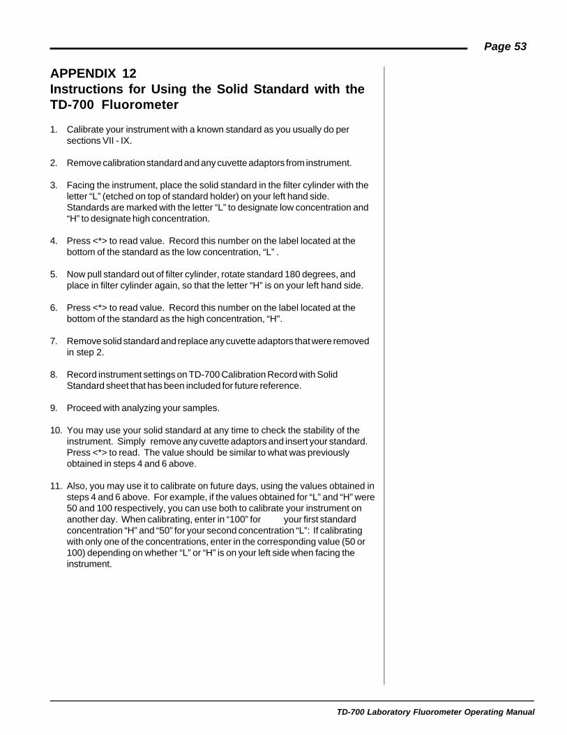
TD-700 Laboratory Fluorometer Operating Manual
Page 53
APPENDIX 12Instructions for Using the Solid Standard with theTD-700 Fluorometer
1. Calibrate your instrument with a known standard as you usually do persections VII - IX.
2. Remove calibration standard and any cuvette adaptors from instrument.
3. Facing the instrument, place the solid standard in the filter cylinder with theletter “L” (etched on top of standard holder) on your left hand side.Standards are marked with the letter “L” to designate low concentration and“H” to designate high concentration.
4. Press <*> to read value. Record this number on the label located at thebottom of the standard as the low concentration, “L” .
5. Now pull standard out of filter cylinder, rotate standard 180 degrees, andplace in filter cylinder again, so that the letter “H” is on your left hand side.
6. Press <*> to read value. Record this number on the label located at thebottom of the standard as the high concentration, “H".
7. Remove solid standard and replace any cuvette adaptors that were removedin step 2.
8. Record instrument settings on TD-700 Calibration Record with SolidStandard sheet that has been included for future reference.
9. Proceed with analyzing your samples.
10. You may use your solid standard at any time to check the stability of theinstrument. Simply remove any cuvette adaptors and insert your standard.Press <*> to read. The value should be similar to what was previouslyobtained in steps 4 and 6 above.
11. Also, you may use it to calibrate on future days, using the values obtained insteps 4 and 6 above. For example, if the values obtained for “L” and “H” were50 and 100 respectively, you can use both to calibrate your instrument onanother day. When calibrating, enter in “100” for your first standardconcentration “H” and “50” for your second concentration “L”: If calibratingwith only one of the concentrations, enter in the corresponding value (50 or100) depending on whether “L” or “H” is on your left side when facing theinstrument.
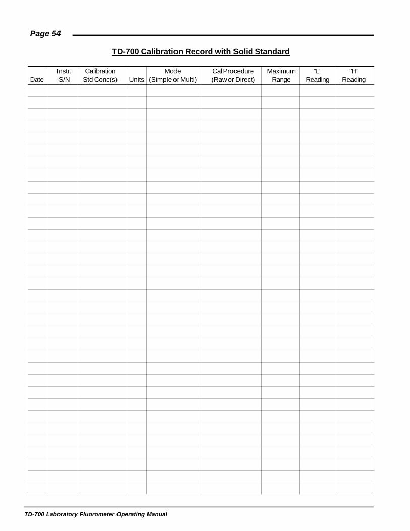
TD-700 Laboratory Fluorometer Operating Manual
Page 54
TD-700 Calibration Record with Solid Standard
Instr. Calibration Mode Cal Procedure Maximum “L” “H”Date S/N Std Conc(s) Units (Simple or Multi) (Raw or Direct) Range Reading Reading